EP2637258A2 - Klemme und Anschlussstruktur davon - Google Patents
Klemme und Anschlussstruktur davon Download PDFInfo
- Publication number
- EP2637258A2 EP2637258A2 EP13158373.4A EP13158373A EP2637258A2 EP 2637258 A2 EP2637258 A2 EP 2637258A2 EP 13158373 A EP13158373 A EP 13158373A EP 2637258 A2 EP2637258 A2 EP 2637258A2
- Authority
- EP
- European Patent Office
- Prior art keywords
- terminal
- section
- connecting holder
- terminal section
- tip end
- Prior art date
- Legal status (The legal status is an assumption and is not a legal conclusion. Google has not performed a legal analysis and makes no representation as to the accuracy of the status listed.)
- Granted
Links
Images




Classifications
-
- H—ELECTRICITY
- H01—ELECTRIC ELEMENTS
- H01R—ELECTRICALLY-CONDUCTIVE CONNECTIONS; STRUCTURAL ASSOCIATIONS OF A PLURALITY OF MUTUALLY-INSULATED ELECTRICAL CONNECTING ELEMENTS; COUPLING DEVICES; CURRENT COLLECTORS
- H01R13/00—Details of coupling devices of the kinds covered by groups H01R12/70 or H01R24/00 - H01R33/00
- H01R13/02—Contact members
- H01R13/04—Pins or blades for co-operation with sockets
-
- H—ELECTRICITY
- H01—ELECTRIC ELEMENTS
- H01H—ELECTRIC SWITCHES; RELAYS; SELECTORS; EMERGENCY PROTECTIVE DEVICES
- H01H1/00—Contacts
- H01H1/58—Electric connections to or between contacts; Terminals
- H01H1/5866—Electric connections to or between contacts; Terminals characterised by the use of a plug and socket connector
-
- H—ELECTRICITY
- H01—ELECTRIC ELEMENTS
- H01R—ELECTRICALLY-CONDUCTIVE CONNECTIONS; STRUCTURAL ASSOCIATIONS OF A PLURALITY OF MUTUALLY-INSULATED ELECTRICAL CONNECTING ELEMENTS; COUPLING DEVICES; CURRENT COLLECTORS
- H01R13/00—Details of coupling devices of the kinds covered by groups H01R12/70 or H01R24/00 - H01R33/00
- H01R13/02—Contact members
- H01R13/10—Sockets for co-operation with pins or blades
- H01R13/11—Resilient sockets
- H01R13/112—Resilient sockets forked sockets having two legs
-
- H—ELECTRICITY
- H01—ELECTRIC ELEMENTS
- H01H—ELECTRIC SWITCHES; RELAYS; SELECTORS; EMERGENCY PROTECTIVE DEVICES
- H01H1/00—Contacts
- H01H1/12—Contacts characterised by the manner in which co-operating contacts engage
- H01H1/36—Contacts characterised by the manner in which co-operating contacts engage by sliding
- H01H1/365—Bridging contacts
-
- H—ELECTRICITY
- H01—ELECTRIC ELEMENTS
- H01H—ELECTRIC SWITCHES; RELAYS; SELECTORS; EMERGENCY PROTECTIVE DEVICES
- H01H1/00—Contacts
- H01H1/12—Contacts characterised by the manner in which co-operating contacts engage
- H01H1/36—Contacts characterised by the manner in which co-operating contacts engage by sliding
- H01H1/40—Contact mounted so that its contact-making surface is flush with adjoining insulation
-
- H—ELECTRICITY
- H01—ELECTRIC ELEMENTS
- H01H—ELECTRIC SWITCHES; RELAYS; SELECTORS; EMERGENCY PROTECTIVE DEVICES
- H01H13/00—Switches having rectilinearly-movable operating part or parts adapted for pushing or pulling in one direction only, e.g. push-button switch
- H01H13/50—Switches having rectilinearly-movable operating part or parts adapted for pushing or pulling in one direction only, e.g. push-button switch having a single operating member
- H01H13/52—Switches having rectilinearly-movable operating part or parts adapted for pushing or pulling in one direction only, e.g. push-button switch having a single operating member the contact returning to its original state immediately upon removal of operating force, e.g. bell-push switch
-
- H—ELECTRICITY
- H01—ELECTRIC ELEMENTS
- H01R—ELECTRICALLY-CONDUCTIVE CONNECTIONS; STRUCTURAL ASSOCIATIONS OF A PLURALITY OF MUTUALLY-INSULATED ELECTRICAL CONNECTING ELEMENTS; COUPLING DEVICES; CURRENT COLLECTORS
- H01R12/00—Structural associations of a plurality of mutually-insulated electrical connecting elements, specially adapted for printed circuits, e.g. printed circuit boards [PCB], flat or ribbon cables, or like generally planar structures, e.g. terminal strips, terminal blocks; Coupling devices specially adapted for printed circuits, flat or ribbon cables, or like generally planar structures; Terminals specially adapted for contact with, or insertion into, printed circuits, flat or ribbon cables, or like generally planar structures
- H01R12/70—Coupling devices
- H01R12/71—Coupling devices for rigid printing circuits or like structures
- H01R12/712—Coupling devices for rigid printing circuits or like structures co-operating with the surface of the printed circuit or with a coupling device exclusively provided on the surface of the printed circuit
- H01R12/716—Coupling device provided on the PCB
-
- H—ELECTRICITY
- H01—ELECTRIC ELEMENTS
- H01R—ELECTRICALLY-CONDUCTIVE CONNECTIONS; STRUCTURAL ASSOCIATIONS OF A PLURALITY OF MUTUALLY-INSULATED ELECTRICAL CONNECTING ELEMENTS; COUPLING DEVICES; CURRENT COLLECTORS
- H01R13/00—Details of coupling devices of the kinds covered by groups H01R12/70 or H01R24/00 - H01R33/00
- H01R13/02—Contact members
- H01R13/26—Pin or blade contacts for sliding co-operation on one side only
-
- H—ELECTRICITY
- H01—ELECTRIC ELEMENTS
- H01R—ELECTRICALLY-CONDUCTIVE CONNECTIONS; STRUCTURAL ASSOCIATIONS OF A PLURALITY OF MUTUALLY-INSULATED ELECTRICAL CONNECTING ELEMENTS; COUPLING DEVICES; CURRENT COLLECTORS
- H01R13/00—Details of coupling devices of the kinds covered by groups H01R12/70 or H01R24/00 - H01R33/00
- H01R13/64—Means for preventing incorrect coupling
Definitions
- the present invention relates to a terminal used for an electronic device, particularly switchgear such as a relay and a switch, and a connection structure of the same.
- a terminal used for a switch and the like for example, DE 10,061,112 A1 describes a terminal in which an insulation displacement terminal is used as an externally connecting terminal and a terminal on the side of a connecting holder passes through the insulation displacement terminal, so that the switch can be operated.
- the present invention has been devised to solve the above problem, and an object thereof is to provide a small terminal capable of being reduced in size, and a connection structure of the same.
- a terminal section of the terminal is cut out from a branch portion toward a tip end of the terminal section in the longitudinal direction, and includes a bent portion position closer to the tip end.
- the terminal section is bent on the tip end side from the branch portion, a distance from a base portion of the terminal to a bent portion is increased. Therefore, the terminal is easily held at the time of bending processing of the later step, so that variations in processing precision of the terminal at the time of the bending processing are reduced. By decreasing a distance from the bent portion to a tip end of the terminal, variations in length size to the tip end due to bending can be suppressed. Further, the terminal section is formed by cutting out in the longitudinal direction and bending.
- width size of the terminal section can be formed in such a manner that the terminal section does not protrude out from an outer circumferential surface of a housing, and even for a switch installed in the direction in which a push button is horizontally operated, the terminal section can be connected to connection terminals from two directions.
- a width of the base portion of the terminal section may be narrower than the branch portion. According to the above configuration, the terminal section is easily deformed at the time of inserting the connected terminals. Therefore, there is an advantage that an influence of deformation on a part which is influential on a contact operation can be suppressed to minimum, and hence an adverse influence on airtightness of a main body of the housing and operation characteristics can be minimized.
- the terminal may include the narrow base portion, the branch portion, whose width is wider than width of the base portion, extending from the base portion, the bent portion bent from the branch portion, and a pair of nipping portions extending from the bent portion, and a distance from the base portion to the bent portion may be longer than a distance from the bent portion to tip ends of the nipping portions.
- the terminal section can be bent on the tip end side, so that the variations in the processing precision of the terminal and the variations in the length size to the tip end due to the bending can be suppressed.
- a tip end of the terminal section may be arranged so as to be in a same plane with an outer periphery circumferential surface of the housing.
- the terminal section may be inserted into an acceptance side of connection terminals in a manner that the terminal section enters the connection terminals from the bent portion into and nipped by the connected terminals protruding on an inward surface of a connecting holder which has an opening at least in one direction. Thereby, a height of the connected terminals can be decreased.
- the circumference can be sealed with a small amount of resin.
- the terminal section may be inserted from the nipping portions into and nipped by the connected terminals protruding on an inward surface of a connecting holder which has an opening at least in one direction.
- the terminal can be connected to the connecting holder by various methods.
- a positioning projection section provided on the outer circumferential surface of the housing may be fitted into an insertion hole formed on the inward surface.
- the housing is easily positioned on the connecting holder, so that the workability at the time of press-fitting the housing into the connecting holder is improved. Since the housing is fixed to the connecting holder via the positioning projection section, contact reliability between the terminal section and the connected terminal can be maintained.
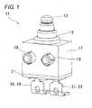
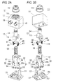
- a switch 11 provided with terminals 33, 38 includes a push button 12, a casing (housing) 17, a base 21, a first fixing terminal 31, a second fixing terminal 36, and a slider 41 as shown in Figs. 1 , 2A, and 2B .
- the push button 12 has a seat 13 in which a recessed portion is formed, and a cylindrical pressed section 14 extending upward from the seat 13 in the axial direction.
- the push button 12 is arranged inside the casing (housing) 17 movably in the axial direction orthogonal to the base 21, and an upper end of the pressed section 14 protrudes upward from the casing (housing) 17 through a cylindrical cap 15. Therefore, the pressed section 14 is pressed from an exterior, so that the push button 12 is moved in the axial direction.
- the housing 17 is formed in a box shape in which a bottom portion is opened, and has an annular groove 18 formed on an upper surface thereof, the annular groove through which the pressed section 14 of the push button 12 is inserted, and a pair of annular positioning projection sections 19 horizontally protruding from a side surface thereof.
- the base 21 is a plate shape resin body for closing an opening in the bottom portion of the housing 17.
- an insulating wall section 22 extending upward is integrally formed on an upper surface thereof, and a cylindrical rib 23 protruding upward is provided in a center of the base 21.
- the insulating wall section 22 includes a burying groove 25 formed in a rectangular shape in a front view and provided on an inner surface thereof, the burying groove into which the first fixing terminal 31 is buried, and an insulation portion 26 provided on the upper side of the burying groove 25. Further, terminal holes 27 through which the first fixing terminal 31 and the second fixing terminal 36 are inserted are formed in the base 21.
- the first fixing terminal 31 is made of metal, and has a rectangular plate shape first slide contact section 32 formed in an upper half part thereof extending in the axial direction, and a first externally connecting terminal section 33 formed in a lower half part thereof.
- the first externally connecting terminal section 33 is formed in an L shape, and bent so as to be orthogonal to the axial direction on the opposite side of the protruding direction of the positioning projection sections 19 of the housing 17.
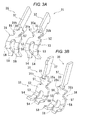
- the first externally connecting terminal section 33 has a base portion 51, a branch portion 52, bent portions 53, and a pair of nipping portions 54 as shown in Figs. 3A and 3B .
- the base portion 51 continues to the first slide contact section 32 via a coupling section 35, and is formed to be narrow.
- the branch portion 52 extends from the base portion 51 on the opposite side of the first slide contact section 32, and is formed to be wide.
- the first externally connecting terminal section 33 is cut out from the branch portion 52 toward a tip end.
- the bent portions 53 are placed on the tip end side of the branch portion 52 and placed on the tip end side of a longitudinal center of the first externally connecting terminal section 33, and bent so as to be orthogonal to the branch portion 52.
- the pair of nipping portions 54 extends from the bent portions 53 and nips a connection fitting 67 (connected terminal, refer to Fig. 5 ) described later.
- the first slide contact section 32 and the first externally connecting terminal section 33 are coupled so as to be orthogonal to each other.
- a first inward projection 35a, and a first outward projection 35b protruding on the opposite side of the first inward projection 35a are formed in the coupling section 35.
- the second fixing terminal 36 is made of metal, and has a rectangular plate shape second slide contact section 37 formed in an upper half part thereof extending in the axial direction, and a second externally connecting terminal section 38 formed in a lower half part thereof.
- the second externally connecting terminal section 38 is formed in an L shape, and bent so as to be orthogonal to the axial direction on the opposite side of the protruding direction of the positioning projection sections 19 of the housing 17.
- the second externally connecting terminal section 38 has a base portion 56, a branch portion 57, bent portions 58, and a pair of nipping portions 59.
- the base portion 56 continues to the second slide contact section 37 via a coupling section 39, and is formed to be narrow.
- the branch portion 57 extends from the base portion 56 on the opposite side of the second slide contact section 37, and is formed to be wide.
- the second externally connecting terminal section 38 is cut out from the branch portion 57 toward a tip end.
- the bent portions 58 are placed on the tip end side of the branch portion 57 and placed on the tip end side of a longitudinal center of the second externally connecting terminal section 38, and bent so as to be orthogonal to the branch portion 57.
- the pair of nipping portions 59 extends from the bent portions 58 and nips a connection fitting 67 (refer to Fig. 5 ) described later.
- the second slide contact section 37 and the second externally connecting terminal section 38 are coupled so as to be orthogonal to each other.
- a second inward projection 39a, and a second outward projection 39b protruding on the opposite side of the second inward projection 39a are formed in the coupling section 39.
- the second slide contact section 37 is formed to be longer than the first slide contact section 32 of the first fixing terminal 31. In a state that the second fixing terminal 36 is fixed to the base 21 via the terminal hole 27, the second slide contact section 37 is always in contact with the slider 41. Meanwhile, the second externally connecting terminal section 38 is exposed downward from the terminal hole 27 and connected to the connection fitting 67.
- the first externally connecting terminal section 33 and the second externally connecting terminal section 38 are bent on the tip end side thereof.
- a distance L1 from the base portions 51, 56 to the bent portions 53, 58 is longer than a distance L2 from the bent portions 53, 58 to tip ends of the nipping portions 54, 59 (refer to Fig. 4 ). Since the distance L1 from the base portions 51, 56 to the bent portions 53, 58 is longer, the externally connecting terminal sections 33, 38 are easily held at the time of bending processing of the later step, so that variations in processing precision of the terminals at the time of the bending processing are reduced.
- the distance L2 from the bent portions 53, 58 to the tip ends of the nipping portions 54, 59 is shorter, variations in length size to the tip ends due to bending can be suppressed.
- the externally connecting terminal sections 33, 38 are formed by cutting out in the longitudinal direction and bending, width size of the externally connecting terminal sections 33, 38 can be reduced smaller than an outside width of the switch 11 in comparison to the conventional example.
- the connection fittings 67 can be inserted into the externally connecting terminal sections 33, 38 from two up and down directions.
- the slider 41 has a plate shape coupling body 42, and elastic arm sections 43 formed by bending both ends of the coupling body 42.
- Movable contact portions 48, 48 to be brought into sliding contact with the insulation portion 26 of the insulating wall section 22 or the first fixing terminal 31, and movable contact portions 49, 49 to be brought into sliding contact with the second fixing terminal 36 are formed in tip ends of the elastic arm sections 43.
- the cap 15 is fitted into the annular groove 18 of the housing 17.
- the push button 12 is inserted inside the housing 17 movably in the axial direction, so that the upper end of the pressed section 14 protrudes from the cap 15.
- the slider 41 is fixed to the recessed portion of the seat 13 of the push button 12 by insert-molding, thermal caulking, or snap-fitting.
- an upper end of a coil spring 50 is abutted with the recessed portion of the seat 13.
- the first fixing terminal 31 is insert-molded to the base 21 in advance so that the first inward projection 35a and the first outward projection 35b of the first fixing terminal 31 are buried in the base 21.
- the first slide contact section 32 of the first fixing terminal 31 is buried in the burying groove 25 of the insulating wall section 22 so as to be flush with the insulation portion 26 (refer to Fig. 10A ). Therefore, the slider 41 can be brought into smooth sliding contact with the insulation portion 26 and the first fixing terminal 31.
- the second fixing terminal 36 is insert-molded to the base 21 in advance so that the second inward projection 39a and the second outward projection 39b of the second fixing terminal 36 are buried in the base 21.
- the base 21 is installed in the opening of the housing 17 so that the cylindrical rib 23 of the base 21 is engaged with a lower end of the coil spring 50 so as to compress the coil spring 50, and the first fixing terminal 31 and the second fixing terminal 36 are accommodated inside the housing 17. Thereby, the switch 11 is completed.
- tip end positions of the first externally connecting terminal section 33 and the second externally connecting terminal section 38, that is, ends of the nipping portions 54, 59 match with a plane F extending from an outside form of the housing 17 (refer to Fig. 4 ).
- the assembled switch 11 is press-fitted into a connecting holder 61 shown in Fig. 5 .
- the connecting holder 61 has for example a substrate 62, and a pair of side plates 63 vertically standing up from both edges of the substrate 62 and facing each other. On inner surfaces of the side plates 63, linear ribs 64 protruding inward are formed.
- a press-fit section 65 into which the switch 11 is press-fitted is partitioned by the linear ribs 64.
- a pair of circular insertion holes 66 is formed in the substrate 62 of the press-fit section 65. In an end facing the circular insertion holes 66 of the substrate 62 across the linear ribs 64, the pair of connection fittings 67 is provided in line.
- the housing 17 of the switch 11 is positioned to the press-fit section 65 of the connecting holder 61 and press-fitted downward.
- the tip end positions of the first externally connecting terminal section 33 and the second externally connecting terminal section 38 match with the plane F extending from the outside form of the housing 17 (refer to Fig. 4 ). Therefore, by simultaneously pushing the housing 17 and tip ends of the externally connecting terminal sections 33, 38 by a flat jig, the switch 11 can be press-fitted into the connecting holder 61.
- workability at the time of press-fitting can be improved.
- the positioning projection sections 19 of the switch 11 are fitted into the circular insertion holes 66 of the connecting holder 61.
- the housing 17 is easily positioned to the connecting holder 61, so that the workability at the time of press-fitting the housing 17 into the connecting holder 61 is improved. Since the housing 17 is fixed to the connecting holder 61 via the positioning projection sections 19, contact reliability between the first externally connecting terminal section 33 and the second externally connecting terminal section 38 and the connection fittings 67 can be maintained.
- connection fittings 67 are guided between the nipping portions 54, 59 so that the connection fittings 67 are nipped by the nipping portions 54, 54 of the first externally connecting terminal section 33 and the nipping portions 59, 59 of the second externally connecting terminal section 38.
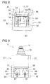
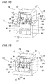
- Fig. 8 by sliding and nipping the connection fittings 67 between the nipping portions 54, 59, the first externally connecting terminal section 33 and the second externally connecting terminal section 38 are connected to the connection fittings 67, so that assembling of the switch 11 to the connecting holder 61 is completed.
- Fig. 8 by sliding and nipping the connection fittings 67 between the nipping portions 54, 59, the first externally connecting terminal section 33 and the second externally connecting terminal section 38 are connected to the connection fittings 67, so that assembling of the switch 11 to the connecting holder 61 is completed.
- connection fittings 67, and the branch portions 52, 57 and the nipping portions 54, 59 are projected on the same plane, ends of the connection fittings 67 are placed between the branch portions 52, 57 and the nipping portions 54, 59.
- the externally connecting terminal sections 33, 38 can be press-fitted into the connection fittings 67.
- the base portions 51, 56 are formed to be narrow.
- the connecting holder 61 is not limited to the above configuration but only required to have a positioning mechanism for press-fitting the externally connecting terminal sections 33, 38 into the connection fittings 67 protruding from the connecting holder 61.
- the slider 41 is biased by the coil spring 50 and placed at an initial position on the upper side.
- the movable contact portions 48, 48 on the one side are abutted with the insulation portion 26 of the insulating wall section 22, and the movable contact portions 49, 49 on the other side are abutted with the second slide contact section 37 of the second fixing terminal 36, so that the switch is insulated.
- the push button 12 is moved with the slider 41 downward in the axial direction against a bias force of the coil spring 50.
- the elastic arm sections 43 are moved downward, and brought into sliding contact with the first slide contact section 32 of the first fixing terminal 31 after the insulation portion 26.
- the movable contact portions 48, 48 on the one side are abutted with the first slide contact section 32 and the movable contact portions 49, 49 on the other side are abutted with the second slide contact section 37, so that the switch is conducted.
- the connection fittings respectively connected to the first and second externally connecting terminal sections 33, 38 are brought into a conduction state.
- the elastic arm sections 43 are moved upward, brought into sliding contact with the insulation portion 26 after the first slide contact section 32, and returned to the initial position.
- the movable contact portions 48, 48 on the one side are abutted with the insulation portion 26 of the insulating wall section 22, and the movable contact portions 49, 49 on the other side are abutted with the second slide contact section 37, so that the switch is brought into a non-conducting state.
- the first externally connecting terminal section 33 and the second externally connecting terminal section 38 are bent in the opposite direction to the protruding direction of the positioning projection sections 19 of the housing 17.
- the present invention is not limited to this.
- a base 21 to which a first externally connecting terminal section 33 and a second externally connecting terminal section 38 are insert-molded is rotated by 180° and installed in a housing 17.
- the first externally connecting terminal section 33 and the second externally connecting terminal section 38 are bent in the same direction as the protruding direction of positioning projection sections 19.
- the second embodiment is the same as the first embodiment.
- the same parts will be given the same reference numerals and description thereof will not be repeated.
- the housing 17 of the switch 70 is positioned to a press-fit section 65 of the connecting holder 61 and press-fitted downward.
- the positioning projection sections 19 of the switch 70 are guided and fitted into circular insertion holes 66 of the connecting holder 61.
- connection fittings 67 are guided between nipping portions 54, 59 so that the connection fittings 67 are nipped by the nipping portions 54, 54 of the first externally connecting terminal section 33 and the nipping portions 59, 59 of the second externally connecting terminal section 38.
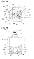
- connection fittings 67 By sliding and nipping the connection fittings 67 between the nipping portions 54, 59, the first externally connecting terminal section 33 and the second externally connecting terminal section 38 are connected to the connection fittings 67, so that assembling of the switch 70 to the connecting holder 61 is completed. Since the first externally connecting terminal section 33 and the second externally connecting terminal section 38 are bent in the same direction as the protruding direction of the positioning projection sections 19, a height of the connection fittings 67 can be decreased. At the time of sealing circumferences of the first externally connecting terminal section 33 and the second externally connecting terminal section 38 with an insulating resin, the circumferences can be sealed even with a small amount of resin. As shown in Fig.
- connection fittings 67, and branch portions 52, 57 and the nipping portions 54, 59 are projected on the same plane, ends of the connection fittings 67 are placed between the branch portions 52, 57 and the nipping portions 54, 59.
- the connection fittings 67 can be press-fitted into the externally connecting terminal sections 33, 38.
- the connecting holder 61 is not limited to the above configuration but only required to have a positioning mechanism for press-fitting the externally connecting terminal sections 33, 38 into the connection fittings 67 protruding from the connecting holder 61.
- terminals of the present invention may be adopted for any of a fixed contact and a movable contact of an electric device such as a relay and a switch as a matter of course.
Landscapes
- Physics & Mathematics (AREA)
- Electromagnetism (AREA)
- Switch Cases, Indication, And Locking (AREA)
- Push-Button Switches (AREA)
- Connector Housings Or Holding Contact Members (AREA)
- Connections Arranged To Contact A Plurality Of Conductors (AREA)
Applications Claiming Priority (1)
| Application Number | Priority Date | Filing Date | Title |
|---|---|---|---|
| JP2012053566A JP5924038B2 (ja) | 2012-03-09 | 2012-03-09 | 端子の接続構造 |
Publications (3)
| Publication Number | Publication Date |
|---|---|
| EP2637258A2 true EP2637258A2 (de) | 2013-09-11 |
| EP2637258A3 EP2637258A3 (de) | 2013-12-11 |
| EP2637258B1 EP2637258B1 (de) | 2016-02-03 |
Family
ID=47844173
Family Applications (1)
| Application Number | Title | Priority Date | Filing Date |
|---|---|---|---|
| EP13158373.4A Active EP2637258B1 (de) | 2012-03-09 | 2013-03-08 | Klemme und Anschlussstruktur davon |
Country Status (5)
| Country | Link |
|---|---|
| US (1) | US9153891B2 (de) |
| EP (1) | EP2637258B1 (de) |
| JP (1) | JP5924038B2 (de) |
| CN (1) | CN103311002B (de) |
| CA (1) | CA2809559C (de) |
Cited By (1)
| Publication number | Priority date | Publication date | Assignee | Title |
|---|---|---|---|---|
| EP3745436A1 (de) * | 2019-05-23 | 2020-12-02 | Kedu Electric Co ., Ltd | Integrierter schalter |
Families Citing this family (8)
| Publication number | Priority date | Publication date | Assignee | Title |
|---|---|---|---|---|
| JP6217661B2 (ja) * | 2015-01-30 | 2017-10-25 | コニカミノルタ株式会社 | 画像形成装置 |
| CN205211631U (zh) * | 2015-11-20 | 2016-05-04 | 光宝电子(广州)有限公司 | 按键模组及具有该按键模组的装置 |
| EP3455869B1 (de) * | 2016-05-11 | 2023-08-23 | Safran Electrical & Power | Schutzschalter mit pressfassung |
| CN107645082A (zh) * | 2016-07-22 | 2018-01-30 | 四川日机密封件股份有限公司 | 电气连接装置 |
| JP6838484B2 (ja) * | 2017-04-28 | 2021-03-03 | オムロン株式会社 | スイッチ |
| WO2019019099A1 (en) * | 2017-07-27 | 2019-01-31 | Ledvance Gmbh | LAMP SOCKET, LAMP BASE, LIGHTING DEVICE AND LIGHTING SYSTEM |
| CN110247221B (zh) * | 2018-03-09 | 2024-09-06 | 南京大全电气研究院有限公司 | 组合式出线装置 |
| DE112020001967T5 (de) * | 2019-04-16 | 2022-01-05 | Alps Alpine Co., Ltd. | Umschalter und verfahren zur herstellung einer anschlussklemme |
Citations (1)
| Publication number | Priority date | Publication date | Assignee | Title |
|---|---|---|---|---|
| DE10061112A1 (de) | 1999-12-11 | 2001-06-13 | Marquardt Gmbh | Steckverbindung für elektrische Bauelemente |
Family Cites Families (11)
| Publication number | Priority date | Publication date | Assignee | Title |
|---|---|---|---|---|
| GB1443644A (en) * | 1973-03-01 | 1976-07-21 | Bunker Ramo | Electrical socket and socket contact adapted for use therewith machine for picking hops |
| IT1179206B (it) * | 1984-06-13 | 1987-09-16 | Texas Instruments Italia Spa | Connettore elettrico e suo procedimento di fabbricazione |
| US4813881A (en) | 1986-12-29 | 1989-03-21 | Labinal Components And Systems, Inc. | Variable insertion force contact |
| US4992056A (en) * | 1989-02-27 | 1991-02-12 | Amp Incorporated | Surface mount electrical connector and an electrical terminal therefor |
| JPH0425122U (de) * | 1990-06-26 | 1992-02-28 | ||
| DE4330390C2 (de) * | 1993-09-08 | 1995-10-26 | Erni Elektroapp | Einteilige, zweischenklige Kontaktfeder |
| WO1997045896A1 (en) * | 1996-05-30 | 1997-12-04 | The Whitaker Corporation | Surface mountable electrical connector |
| JP4323795B2 (ja) * | 2002-12-24 | 2009-09-02 | パナソニック電工株式会社 | スイッチ装置 |
| FR2861505B1 (fr) * | 2003-10-27 | 2010-09-03 | Ixfin Magneti Marelli Systemes | Systeme de connexion sans soudure pour cartes a circuits imprimes |
| JP2008300167A (ja) * | 2007-05-31 | 2008-12-11 | Sumitomo Wiring Syst Ltd | 音叉端子の基板への取付構造 |
| DE102008045810B4 (de) * | 2008-09-05 | 2010-09-02 | Tyco Electronics Amp Gmbh | Elektrischer Gabelkontakt für ein Stanzgitter, sowie elektrisches Stanzgitter |
-
2012
- 2012-03-09 JP JP2012053566A patent/JP5924038B2/ja active Active
-
2013
- 2013-03-08 CN CN201310075191.3A patent/CN103311002B/zh active Active
- 2013-03-08 US US13/791,739 patent/US9153891B2/en active Active
- 2013-03-08 EP EP13158373.4A patent/EP2637258B1/de active Active
- 2013-03-08 CA CA2809559A patent/CA2809559C/en active Active
Patent Citations (1)
| Publication number | Priority date | Publication date | Assignee | Title |
|---|---|---|---|---|
| DE10061112A1 (de) | 1999-12-11 | 2001-06-13 | Marquardt Gmbh | Steckverbindung für elektrische Bauelemente |
Cited By (2)
| Publication number | Priority date | Publication date | Assignee | Title |
|---|---|---|---|---|
| EP3745436A1 (de) * | 2019-05-23 | 2020-12-02 | Kedu Electric Co ., Ltd | Integrierter schalter |
| US11120954B2 (en) | 2019-05-23 | 2021-09-14 | Kedu Electric Co., Ltd. | Integrated switch |
Also Published As
| Publication number | Publication date |
|---|---|
| EP2637258B1 (de) | 2016-02-03 |
| US20130273788A1 (en) | 2013-10-17 |
| CA2809559A1 (en) | 2013-09-09 |
| US9153891B2 (en) | 2015-10-06 |
| CN103311002A (zh) | 2013-09-18 |
| JP5924038B2 (ja) | 2016-05-25 |
| JP2013187155A (ja) | 2013-09-19 |
| CA2809559C (en) | 2015-09-15 |
| EP2637258A3 (de) | 2013-12-11 |
| CN103311002B (zh) | 2016-07-20 |
Similar Documents
| Publication | Publication Date | Title |
|---|---|---|
| EP2637258B1 (de) | Klemme und Anschlussstruktur davon | |
| EP2637184B1 (de) | Schalter | |
| EP3336973B1 (de) | Koaxialverbinder mit schwebemechanismus | |
| US7025598B2 (en) | Coaxial electrical connector | |
| CN111952811B (zh) | 连接方法、连接结构和连接端子组装件 | |
| US20140377986A1 (en) | Spring Connector with Waterproofing Function | |
| JP5020155B2 (ja) | コンタクト | |
| US10256569B2 (en) | Connector | |
| CN107240786A (zh) | 端子装置及具有该端子装置的布线设备 | |
| KR101287093B1 (ko) | 스위치 장치 | |
| EP3293830A1 (de) | Schutzelement- und leiterplattenmontagestruktur eines schienenanschlusses | |
| KR101685603B1 (ko) | 동축 커넥터 및 그 조립방법 | |
| US7880103B2 (en) | Microswitch with push-in wire connector | |
| CN111279171B (zh) | 传感器用连接器 | |
| JP2017036878A (ja) | マイクロスイッチおよび空調装置 |
Legal Events
| Date | Code | Title | Description |
|---|---|---|---|
| PUAI | Public reference made under article 153(3) epc to a published international application that has entered the european phase |
Free format text: ORIGINAL CODE: 0009012 |
|
| 17P | Request for examination filed |
Effective date: 20130308 |
|
| AK | Designated contracting states |
Kind code of ref document: A2 Designated state(s): AL AT BE BG CH CY CZ DE DK EE ES FI FR GB GR HR HU IE IS IT LI LT LU LV MC MK MT NL NO PL PT RO RS SE SI SK SM TR |
|
| AX | Request for extension of the european patent |
Extension state: BA ME |
|
| PUAL | Search report despatched |
Free format text: ORIGINAL CODE: 0009013 |
|
| AK | Designated contracting states |
Kind code of ref document: A3 Designated state(s): AL AT BE BG CH CY CZ DE DK EE ES FI FR GB GR HR HU IE IS IT LI LT LU LV MC MK MT NL NO PL PT RO RS SE SI SK SM TR |
|
| AX | Request for extension of the european patent |
Extension state: BA ME |
|
| RIC1 | Information provided on ipc code assigned before grant |
Ipc: H01R 13/11 20060101AFI20131107BHEP Ipc: H01H 13/04 20060101ALI20131107BHEP Ipc: H01H 1/58 20060101ALI20131107BHEP Ipc: H01H 1/36 20060101ALI20131107BHEP |
|
| GRAP | Despatch of communication of intention to grant a patent |
Free format text: ORIGINAL CODE: EPIDOSNIGR1 |
|
| RIC1 | Information provided on ipc code assigned before grant |
Ipc: H01H 1/36 20060101ALI20150731BHEP Ipc: H01R 12/71 20110101ALI20150731BHEP Ipc: H01R 13/04 20060101ALI20150731BHEP Ipc: H01H 13/52 20060101ALI20150731BHEP Ipc: H01R 13/64 20060101ALI20150731BHEP Ipc: H01H 1/58 20060101ALI20150731BHEP Ipc: H01R 13/26 20060101ALI20150731BHEP Ipc: H01R 13/11 20060101AFI20150731BHEP Ipc: H01H 13/04 20060101ALI20150731BHEP Ipc: H01H 1/40 20060101ALI20150731BHEP |
|
| INTG | Intention to grant announced |
Effective date: 20150828 |
|
| RIN1 | Information on inventor provided before grant (corrected) |
Inventor name: HIROTO, YONEHARA Inventor name: HIROYUKI, FUJITA |
|
| GRAS | Grant fee paid |
Free format text: ORIGINAL CODE: EPIDOSNIGR3 |
|
| GRAA | (expected) grant |
Free format text: ORIGINAL CODE: 0009210 |
|
| AK | Designated contracting states |
Kind code of ref document: B1 Designated state(s): AL AT BE BG CH CY CZ DE DK EE ES FI FR GB GR HR HU IE IS IT LI LT LU LV MC MK MT NL NO PL PT RO RS SE SI SK SM TR |
|
| REG | Reference to a national code |
Ref country code: GB Ref legal event code: FG4D |
|
| REG | Reference to a national code |
Ref country code: AT Ref legal event code: REF Ref document number: 774073 Country of ref document: AT Kind code of ref document: T Effective date: 20160215 Ref country code: CH Ref legal event code: EP |
|
| REG | Reference to a national code |
Ref country code: IE Ref legal event code: FG4D |
|
| REG | Reference to a national code |
Ref country code: DE Ref legal event code: R096 Ref document number: 602013004843 Country of ref document: DE |
|
| REG | Reference to a national code |
Ref country code: FR Ref legal event code: PLFP Year of fee payment: 4 |
|
| REG | Reference to a national code |
Ref country code: LT Ref legal event code: MG4D Ref country code: NL Ref legal event code: MP Effective date: 20160203 |
|
| REG | Reference to a national code |
Ref country code: AT Ref legal event code: MK05 Ref document number: 774073 Country of ref document: AT Kind code of ref document: T Effective date: 20160203 |
|
| PG25 | Lapsed in a contracting state [announced via postgrant information from national office to epo] |
Ref country code: HR Free format text: LAPSE BECAUSE OF FAILURE TO SUBMIT A TRANSLATION OF THE DESCRIPTION OR TO PAY THE FEE WITHIN THE PRESCRIBED TIME-LIMIT Effective date: 20160203 Ref country code: FI Free format text: LAPSE BECAUSE OF FAILURE TO SUBMIT A TRANSLATION OF THE DESCRIPTION OR TO PAY THE FEE WITHIN THE PRESCRIBED TIME-LIMIT Effective date: 20160203 Ref country code: ES Free format text: LAPSE BECAUSE OF FAILURE TO SUBMIT A TRANSLATION OF THE DESCRIPTION OR TO PAY THE FEE WITHIN THE PRESCRIBED TIME-LIMIT Effective date: 20160203 Ref country code: NO Free format text: LAPSE BECAUSE OF FAILURE TO SUBMIT A TRANSLATION OF THE DESCRIPTION OR TO PAY THE FEE WITHIN THE PRESCRIBED TIME-LIMIT Effective date: 20160503 Ref country code: GR Free format text: LAPSE BECAUSE OF FAILURE TO SUBMIT A TRANSLATION OF THE DESCRIPTION OR TO PAY THE FEE WITHIN THE PRESCRIBED TIME-LIMIT Effective date: 20160504 |
|
| PG25 | Lapsed in a contracting state [announced via postgrant information from national office to epo] |
Ref country code: RS Free format text: LAPSE BECAUSE OF FAILURE TO SUBMIT A TRANSLATION OF THE DESCRIPTION OR TO PAY THE FEE WITHIN THE PRESCRIBED TIME-LIMIT Effective date: 20160203 Ref country code: IS Free format text: LAPSE BECAUSE OF FAILURE TO SUBMIT A TRANSLATION OF THE DESCRIPTION OR TO PAY THE FEE WITHIN THE PRESCRIBED TIME-LIMIT Effective date: 20160603 Ref country code: LV Free format text: LAPSE BECAUSE OF FAILURE TO SUBMIT A TRANSLATION OF THE DESCRIPTION OR TO PAY THE FEE WITHIN THE PRESCRIBED TIME-LIMIT Effective date: 20160203 Ref country code: LT Free format text: LAPSE BECAUSE OF FAILURE TO SUBMIT A TRANSLATION OF THE DESCRIPTION OR TO PAY THE FEE WITHIN THE PRESCRIBED TIME-LIMIT Effective date: 20160203 Ref country code: NL Free format text: LAPSE BECAUSE OF FAILURE TO SUBMIT A TRANSLATION OF THE DESCRIPTION OR TO PAY THE FEE WITHIN THE PRESCRIBED TIME-LIMIT Effective date: 20160203 Ref country code: AT Free format text: LAPSE BECAUSE OF FAILURE TO SUBMIT A TRANSLATION OF THE DESCRIPTION OR TO PAY THE FEE WITHIN THE PRESCRIBED TIME-LIMIT Effective date: 20160203 Ref country code: BE Free format text: LAPSE BECAUSE OF NON-PAYMENT OF DUE FEES Effective date: 20160331 Ref country code: PT Free format text: LAPSE BECAUSE OF FAILURE TO SUBMIT A TRANSLATION OF THE DESCRIPTION OR TO PAY THE FEE WITHIN THE PRESCRIBED TIME-LIMIT Effective date: 20160603 Ref country code: SE Free format text: LAPSE BECAUSE OF FAILURE TO SUBMIT A TRANSLATION OF THE DESCRIPTION OR TO PAY THE FEE WITHIN THE PRESCRIBED TIME-LIMIT Effective date: 20160203 Ref country code: PL Free format text: LAPSE BECAUSE OF FAILURE TO SUBMIT A TRANSLATION OF THE DESCRIPTION OR TO PAY THE FEE WITHIN THE PRESCRIBED TIME-LIMIT Effective date: 20160203 |
|
| PG25 | Lapsed in a contracting state [announced via postgrant information from national office to epo] |
Ref country code: EE Free format text: LAPSE BECAUSE OF FAILURE TO SUBMIT A TRANSLATION OF THE DESCRIPTION OR TO PAY THE FEE WITHIN THE PRESCRIBED TIME-LIMIT Effective date: 20160203 Ref country code: DK Free format text: LAPSE BECAUSE OF FAILURE TO SUBMIT A TRANSLATION OF THE DESCRIPTION OR TO PAY THE FEE WITHIN THE PRESCRIBED TIME-LIMIT Effective date: 20160203 |
|
| REG | Reference to a national code |
Ref country code: CH Ref legal event code: PL |
|
| REG | Reference to a national code |
Ref country code: DE Ref legal event code: R097 Ref document number: 602013004843 Country of ref document: DE |
|
| PG25 | Lapsed in a contracting state [announced via postgrant information from national office to epo] |
Ref country code: SM Free format text: LAPSE BECAUSE OF FAILURE TO SUBMIT A TRANSLATION OF THE DESCRIPTION OR TO PAY THE FEE WITHIN THE PRESCRIBED TIME-LIMIT Effective date: 20160203 Ref country code: RO Free format text: LAPSE BECAUSE OF FAILURE TO SUBMIT A TRANSLATION OF THE DESCRIPTION OR TO PAY THE FEE WITHIN THE PRESCRIBED TIME-LIMIT Effective date: 20160203 Ref country code: CZ Free format text: LAPSE BECAUSE OF FAILURE TO SUBMIT A TRANSLATION OF THE DESCRIPTION OR TO PAY THE FEE WITHIN THE PRESCRIBED TIME-LIMIT Effective date: 20160203 Ref country code: SK Free format text: LAPSE BECAUSE OF FAILURE TO SUBMIT A TRANSLATION OF THE DESCRIPTION OR TO PAY THE FEE WITHIN THE PRESCRIBED TIME-LIMIT Effective date: 20160203 |
|
| PLBE | No opposition filed within time limit |
Free format text: ORIGINAL CODE: 0009261 |
|
| STAA | Information on the status of an ep patent application or granted ep patent |
Free format text: STATUS: NO OPPOSITION FILED WITHIN TIME LIMIT |
|
| REG | Reference to a national code |
Ref country code: IE Ref legal event code: MM4A |
|
| PG25 | Lapsed in a contracting state [announced via postgrant information from national office to epo] |
Ref country code: BE Free format text: LAPSE BECAUSE OF FAILURE TO SUBMIT A TRANSLATION OF THE DESCRIPTION OR TO PAY THE FEE WITHIN THE PRESCRIBED TIME-LIMIT Effective date: 20160203 |
|
| 26N | No opposition filed |
Effective date: 20161104 |
|
| PG25 | Lapsed in a contracting state [announced via postgrant information from national office to epo] |
Ref country code: LI Free format text: LAPSE BECAUSE OF NON-PAYMENT OF DUE FEES Effective date: 20160331 Ref country code: CH Free format text: LAPSE BECAUSE OF NON-PAYMENT OF DUE FEES Effective date: 20160331 Ref country code: IE Free format text: LAPSE BECAUSE OF NON-PAYMENT OF DUE FEES Effective date: 20160308 |
|
| REG | Reference to a national code |
Ref country code: FR Ref legal event code: PLFP Year of fee payment: 5 |
|
| PG25 | Lapsed in a contracting state [announced via postgrant information from national office to epo] |
Ref country code: BG Free format text: LAPSE BECAUSE OF FAILURE TO SUBMIT A TRANSLATION OF THE DESCRIPTION OR TO PAY THE FEE WITHIN THE PRESCRIBED TIME-LIMIT Effective date: 20160503 Ref country code: SI Free format text: LAPSE BECAUSE OF FAILURE TO SUBMIT A TRANSLATION OF THE DESCRIPTION OR TO PAY THE FEE WITHIN THE PRESCRIBED TIME-LIMIT Effective date: 20160203 |
|
| PG25 | Lapsed in a contracting state [announced via postgrant information from national office to epo] |
Ref country code: MT Free format text: LAPSE BECAUSE OF FAILURE TO SUBMIT A TRANSLATION OF THE DESCRIPTION OR TO PAY THE FEE WITHIN THE PRESCRIBED TIME-LIMIT Effective date: 20160203 |
|
| REG | Reference to a national code |
Ref country code: FR Ref legal event code: PLFP Year of fee payment: 6 |
|
| PG25 | Lapsed in a contracting state [announced via postgrant information from national office to epo] |
Ref country code: CY Free format text: LAPSE BECAUSE OF FAILURE TO SUBMIT A TRANSLATION OF THE DESCRIPTION OR TO PAY THE FEE WITHIN THE PRESCRIBED TIME-LIMIT Effective date: 20160203 Ref country code: HU Free format text: LAPSE BECAUSE OF FAILURE TO SUBMIT A TRANSLATION OF THE DESCRIPTION OR TO PAY THE FEE WITHIN THE PRESCRIBED TIME-LIMIT; INVALID AB INITIO Effective date: 20130308 |
|
| PG25 | Lapsed in a contracting state [announced via postgrant information from national office to epo] |
Ref country code: MK Free format text: LAPSE BECAUSE OF FAILURE TO SUBMIT A TRANSLATION OF THE DESCRIPTION OR TO PAY THE FEE WITHIN THE PRESCRIBED TIME-LIMIT Effective date: 20160203 Ref country code: LU Free format text: LAPSE BECAUSE OF NON-PAYMENT OF DUE FEES Effective date: 20160308 Ref country code: TR Free format text: LAPSE BECAUSE OF FAILURE TO SUBMIT A TRANSLATION OF THE DESCRIPTION OR TO PAY THE FEE WITHIN THE PRESCRIBED TIME-LIMIT Effective date: 20160203 Ref country code: MC Free format text: LAPSE BECAUSE OF FAILURE TO SUBMIT A TRANSLATION OF THE DESCRIPTION OR TO PAY THE FEE WITHIN THE PRESCRIBED TIME-LIMIT Effective date: 20160203 Ref country code: MT Free format text: LAPSE BECAUSE OF FAILURE TO SUBMIT A TRANSLATION OF THE DESCRIPTION OR TO PAY THE FEE WITHIN THE PRESCRIBED TIME-LIMIT Effective date: 20160331 |
|
| PG25 | Lapsed in a contracting state [announced via postgrant information from national office to epo] |
Ref country code: AL Free format text: LAPSE BECAUSE OF FAILURE TO SUBMIT A TRANSLATION OF THE DESCRIPTION OR TO PAY THE FEE WITHIN THE PRESCRIBED TIME-LIMIT Effective date: 20160203 |
|
| PGFP | Annual fee paid to national office [announced via postgrant information from national office to epo] |
Ref country code: FR Payment date: 20230208 Year of fee payment: 11 |
|
| PGFP | Annual fee paid to national office [announced via postgrant information from national office to epo] |
Ref country code: GB Payment date: 20230202 Year of fee payment: 11 |
|
| GBPC | Gb: european patent ceased through non-payment of renewal fee |
Effective date: 20240308 |
|
| PG25 | Lapsed in a contracting state [announced via postgrant information from national office to epo] |
Ref country code: GB Free format text: LAPSE BECAUSE OF NON-PAYMENT OF DUE FEES Effective date: 20240308 |
|
| PG25 | Lapsed in a contracting state [announced via postgrant information from national office to epo] |
Ref country code: FR Free format text: LAPSE BECAUSE OF NON-PAYMENT OF DUE FEES Effective date: 20240331 |
|
| PG25 | Lapsed in a contracting state [announced via postgrant information from national office to epo] |
Ref country code: GB Free format text: LAPSE BECAUSE OF NON-PAYMENT OF DUE FEES Effective date: 20240308 Ref country code: FR Free format text: LAPSE BECAUSE OF NON-PAYMENT OF DUE FEES Effective date: 20240331 |
|
| PGFP | Annual fee paid to national office [announced via postgrant information from national office to epo] |
Ref country code: IT Payment date: 20250331 Year of fee payment: 13 |
|
| PGFP | Annual fee paid to national office [announced via postgrant information from national office to epo] |
Ref country code: DE Payment date: 20260320 Year of fee payment: 14 |