EP2637266A1 - Laser à cavité externe et système de réseau optique passif à multiplexage par division de longueur d'onde - Google Patents
Laser à cavité externe et système de réseau optique passif à multiplexage par division de longueur d'onde Download PDFInfo
- Publication number
- EP2637266A1 EP2637266A1 EP11849359.2A EP11849359A EP2637266A1 EP 2637266 A1 EP2637266 A1 EP 2637266A1 EP 11849359 A EP11849359 A EP 11849359A EP 2637266 A1 EP2637266 A1 EP 2637266A1
- Authority
- EP
- European Patent Office
- Prior art keywords
- gain medium
- frm
- optical signal
- polarization direction
- ecl
- Prior art date
- Legal status (The legal status is an assumption and is not a legal conclusion. Google has not performed a legal analysis and makes no representation as to the accuracy of the status listed.)
- Withdrawn
Links
Images


Classifications
-
- H—ELECTRICITY
- H04—ELECTRIC COMMUNICATION TECHNIQUE
- H04B—TRANSMISSION
- H04B10/00—Transmission systems employing electromagnetic waves other than radio-waves, e.g. infrared, visible or ultraviolet light, or employing corpuscular radiation, e.g. quantum communication
- H04B10/50—Transmitters
- H04B10/501—Structural aspects
- H04B10/503—Laser transmitters
-
- H—ELECTRICITY
- H01—ELECTRIC ELEMENTS
- H01S—DEVICES USING THE PROCESS OF LIGHT AMPLIFICATION BY STIMULATED EMISSION OF RADIATION [LASER] TO AMPLIFY OR GENERATE LIGHT; DEVICES USING STIMULATED EMISSION OF ELECTROMAGNETIC RADIATION IN WAVE RANGES OTHER THAN OPTICAL
- H01S5/00—Semiconductor lasers
- H01S5/10—Construction or shape of the optical resonator, e.g. extended or external cavity, coupled cavities, bent-guide, varying width, thickness or composition of the active region
- H01S5/14—External cavity lasers
- H01S5/141—External cavity lasers using a wavelength selective device, e.g. a grating or etalon
-
- H—ELECTRICITY
- H01—ELECTRIC ELEMENTS
- H01S—DEVICES USING THE PROCESS OF LIGHT AMPLIFICATION BY STIMULATED EMISSION OF RADIATION [LASER] TO AMPLIFY OR GENERATE LIGHT; DEVICES USING STIMULATED EMISSION OF ELECTROMAGNETIC RADIATION IN WAVE RANGES OTHER THAN OPTICAL
- H01S5/00—Semiconductor lasers
- H01S5/10—Construction or shape of the optical resonator, e.g. extended or external cavity, coupled cavities, bent-guide, varying width, thickness or composition of the active region
- H01S5/14—External cavity lasers
-
- H—ELECTRICITY
- H01—ELECTRIC ELEMENTS
- H01Q—ANTENNAS, i.e. RADIO AERIALS
- H01Q11/00—Electrically-long antennas having dimensions more than twice the shortest operating wavelength and consisting of conductive active radiating elements
-
- H—ELECTRICITY
- H01—ELECTRIC ELEMENTS
- H01S—DEVICES USING THE PROCESS OF LIGHT AMPLIFICATION BY STIMULATED EMISSION OF RADIATION [LASER] TO AMPLIFY OR GENERATE LIGHT; DEVICES USING STIMULATED EMISSION OF ELECTROMAGNETIC RADIATION IN WAVE RANGES OTHER THAN OPTICAL
- H01S5/00—Semiconductor lasers
- H01S5/10—Construction or shape of the optical resonator, e.g. extended or external cavity, coupled cavities, bent-guide, varying width, thickness or composition of the active region
- H01S5/14—External cavity lasers
- H01S5/146—External cavity lasers using a fiber as external cavity
-
- H—ELECTRICITY
- H01—ELECTRIC ELEMENTS
- H01S—DEVICES USING THE PROCESS OF LIGHT AMPLIFICATION BY STIMULATED EMISSION OF RADIATION [LASER] TO AMPLIFY OR GENERATE LIGHT; DEVICES USING STIMULATED EMISSION OF ELECTROMAGNETIC RADIATION IN WAVE RANGES OTHER THAN OPTICAL
- H01S5/00—Semiconductor lasers
- H01S5/50—Amplifier structures not provided for in groups H01S5/02 - H01S5/30
- H01S5/5036—Amplifier structures not provided for in groups H01S5/02 - H01S5/30 the arrangement being polarisation-selective
-
- H—ELECTRICITY
- H04—ELECTRIC COMMUNICATION TECHNIQUE
- H04B—TRANSMISSION
- H04B10/00—Transmission systems employing electromagnetic waves other than radio-waves, e.g. infrared, visible or ultraviolet light, or employing corpuscular radiation, e.g. quantum communication
- H04B10/25—Arrangements specific to fibre transmission
- H04B10/2587—Arrangements specific to fibre transmission using a single light source for multiple stations
-
- H—ELECTRICITY
- H04—ELECTRIC COMMUNICATION TECHNIQUE
- H04B—TRANSMISSION
- H04B10/00—Transmission systems employing electromagnetic waves other than radio-waves, e.g. infrared, visible or ultraviolet light, or employing corpuscular radiation, e.g. quantum communication
- H04B10/27—Arrangements for networking
-
- H—ELECTRICITY
- H01—ELECTRIC ELEMENTS
- H01S—DEVICES USING THE PROCESS OF LIGHT AMPLIFICATION BY STIMULATED EMISSION OF RADIATION [LASER] TO AMPLIFY OR GENERATE LIGHT; DEVICES USING STIMULATED EMISSION OF ELECTROMAGNETIC RADIATION IN WAVE RANGES OTHER THAN OPTICAL
- H01S2301/00—Functional characteristics
- H01S2301/14—Semiconductor lasers with special structural design for lasing in a specific polarisation mode
-
- H—ELECTRICITY
- H01—ELECTRIC ELEMENTS
- H01S—DEVICES USING THE PROCESS OF LIGHT AMPLIFICATION BY STIMULATED EMISSION OF RADIATION [LASER] TO AMPLIFY OR GENERATE LIGHT; DEVICES USING STIMULATED EMISSION OF ELECTROMAGNETIC RADIATION IN WAVE RANGES OTHER THAN OPTICAL
- H01S5/00—Semiconductor lasers
- H01S5/06—Arrangements for controlling the laser output parameters, e.g. by operating on the active medium
- H01S5/065—Mode locking; Mode suppression; Mode selection ; Self pulsating
- H01S5/0656—Seeding, i.e. an additional light input is provided for controlling the laser modes, for example by back-reflecting light from an external optical component
-
- H—ELECTRICITY
- H01—ELECTRIC ELEMENTS
- H01S—DEVICES USING THE PROCESS OF LIGHT AMPLIFICATION BY STIMULATED EMISSION OF RADIATION [LASER] TO AMPLIFY OR GENERATE LIGHT; DEVICES USING STIMULATED EMISSION OF ELECTROMAGNETIC RADIATION IN WAVE RANGES OTHER THAN OPTICAL
- H01S5/00—Semiconductor lasers
- H01S5/40—Arrangement of two or more semiconductor lasers, not provided for in groups H01S5/02 - H01S5/30
- H01S5/4012—Beam combining, e.g. by the use of fibres, gratings, polarisers, prisms
-
- H—ELECTRICITY
- H01—ELECTRIC ELEMENTS
- H01S—DEVICES USING THE PROCESS OF LIGHT AMPLIFICATION BY STIMULATED EMISSION OF RADIATION [LASER] TO AMPLIFY OR GENERATE LIGHT; DEVICES USING STIMULATED EMISSION OF ELECTROMAGNETIC RADIATION IN WAVE RANGES OTHER THAN OPTICAL
- H01S5/00—Semiconductor lasers
- H01S5/40—Arrangement of two or more semiconductor lasers, not provided for in groups H01S5/02 - H01S5/30
- H01S5/4025—Array arrangements, e.g. constituted by discrete laser diodes or laser bar
- H01S5/4087—Array arrangements, e.g. constituted by discrete laser diodes or laser bar emitting more than one wavelength
-
- H—ELECTRICITY
- H04—ELECTRIC COMMUNICATION TECHNIQUE
- H04J—MULTIPLEX COMMUNICATION
- H04J14/00—Optical multiplex systems
- H04J14/02—Wavelength-division multiplex systems
- H04J14/0278—WDM optical network architectures
- H04J14/0282—WDM tree architectures
Definitions
- the present invention relates to the field of optical fiber access technologies, in particular, to an External Cavity Laser (ECL) and a system for Wave Division Multiplexing-Passive Optical Network (WDM-PON).
- ECL External Cavity Laser
- WDM-PON Wave Division Multiplexing-Passive Optical Network
- a WDM-PON technology is closely concerned owing to its advantages such as larger bandwidth capacity and a communication manner similar to point-to-point manner that ensures information security.
- the cost of the WDM-PON is higher, and a laser is the most important factor affecting the cost of the WDM-PON.
- FIG. 1 shows a schematic structural diagram of a WDM-PON adopting a self-seeding colorless ECL in the prior art.
- an optical signal emitted by an injection-locked Fabry-Perot laser diode (IL FP-LD) of an Optical Network Unit (ONU) at a user side is transmitted by a branch optical fiber corresponding to the wavelength ⁇ 1, and then passes through a Remote Node Array Waveguide Grating (RN-AWG).
- IL FP-LD injection-locked Fabry-Perot laser diode
- ONU Optical Network Unit
- a part of light is transmitted and sent upward to an Optical Line Terminal (OLT) of a Central Office (CO) through a trunk optical fiber, and the other part of the light is reflected back and then passes through the RN-AWG again, and is re-injected back into the IL FP-LD through the branch optical fiber corresponding to the wavelength ⁇ 1.
- a gain cavity of the IL FP-LD re-amplifies the reflected light and then emits the light out. The process repeats many times in this way, so that an optical fiber laser cavity is formed between the IL FP-LD and the PRM2, and a stable optical signal is output.
- the IL FP-LD also has a modulation function, and therefore, uplink data of the ONU may be modulated to the optical signal generated by oscillation, and at least a part of the optical signal is transmitted through the PRM2, a PRM1 and a Central Office Array Waveguide Grating (CO-AWG) to enter a receiver (Rx) corresponding to the wavelength ⁇ 1 in the OLT.
- the IL FP-LD is a single polarization multi-longitudinal mode laser, and provides different gains for input light in different polarization directions.
- the light reflected back by the PRM2 and transmitted through the branch optical fiber has a random polarization direction. Therefore, the IL FP-LD adopted in the conventional WDM-PON system cannot ensure that the reflected light may obtain a stable gain after being injected back into the IL FP-LD, which causes that output optical power of the IL FP-LD is unstable, and tiny swing of the optical fiber caused by any environmental factor, such as temperature, wind, and ground shock, all result in a dramatic change of the output optical power of the IL FP-LD. Therefore, the prior art cannot solve a problem about polarization dependence of the ECL.
- Embodiments of the present invention provide an ECL and a WDM-PON system, so as to solve a problem of unstable output optical power of a conventional laser caused by polarization dependence.
- An ECL includes a gain medium and a filter, and further includes a Faraday rotator mirror (FRM).
- the gain medium, the filter and the FRM constitute a laser oscillation cavity, and light emitted by the gain medium oscillates back and forth in the oscillation cavity.
- a Passive Optical Network (PON) system includes an OLT and multiple ONUs.
- the OLT communicates with the multiple ONUs in a Wave Division Multiplexing (WDM) manner.
- the OLT includes an ECL configured to provide a data modulation/transmission function, and the ECL is the preceding ECL.
- the FRM is introduced at a reflection end of the ECL, so that a polarization direction of reflected light injected into the gain medium is controllable, therefore, the problem of unstable output optical power of the conventional ECL caused by polarization dependence is effectively solved.
- FIG. 1 is a diagram of a WDM-PON adopting a self-seeding colorless ECL in the prior art
- FIG. 2 is a structural diagram of an ECL according to an embodiment of the present invention.
- FIG. 3 is a working principle diagram of an ECL according to an embodiment of the present invention.
- FIG. 4 is a structural diagram of another ECL according to an embodiment of the present invention.
- FIG. 5 is a structural diagram of another ECL according to an embodiment of the present invention.
- FIG. 6 is a schematic structural diagram of a WDM-PON system according to an embodiment of the present invention.
- FIG. 7 is a schematic structural diagram of another WDM-PON system according to an embodiment of the present invention.
- FIG. 8 is a schematic structural diagram of another WDM-PON system according to an embodiment of the present invention.
- an ECL is provided in an embodiment of the present invention, as shown in FIG. 2 , which includes a gain medium 1, a filter 2, an FRM 3, and optical fibers connecting the preceding members.
- the FRM 3 may be a 45° rotator mirror, and is coupled to an optical fiber between the filter 2 and an output end (not marked) of the ECL, and may rotate a polarization direction of at least a part of optical signals that are incident through the optical fiber through 45 ⁇ 2 degrees and reflect the optical signals back to the optical fiber.
- the FRM 3 may include a Faraday Rotator (FR) and a PRM.
- FR Faraday Rotator
- the FR is a 45° FR, and may rotate a polarization direction of light through 45 degrees, so that incident light needs to pass through the FR twice in the process that the incident light enters the FRM 3, a part of the incident light is reflected by the PRM inside the FRM 3 to generate reflected light, and the reflected light is emitted out of the FRM 3. Therefore, the polarization direction of the reflected light deviates from the polarization direction of the incident light by 90 degrees, that is, the polarization direction of the reflected light is perpendicular to the polarization direction of the incident light.
- the gain medium 1, the filter 2, and the FRM 3 constitute a laser oscillation cavity through the optical fibers.
- the filter 2 carries out a wavelength (mode) selection function in the laser oscillation cavity, and light emitted by the gain medium 1 oscillates back and forth in the oscillation cavity to form laser light.
- a Transverse Magnetic (TM) mode gain of the gain medium 1 is marked as G TM
- a Transverse Electric (TE) mode gain of the gain medium 1 is marked as G TE
- loss of a single link from the gain medium 1 to the 45° FRM is marked as L, where the single link loss L includes coupling loss between the gain medium 1 and the optical fiber, optical loss caused by the filter 2, optical fiber transmission loss, and optical loss caused by the FR and the PRM in the FRM 3.
- the gain medium 1 emits an Amplified Spontaneous Emission (ASE) optical signal, and a polarization direction of the ASE optical signal is identical to a TE direction of the gain medium 1, for example, a polarization direction of Emission 1 (that is, first emission light) as shown in FIG. 3 .
- ASE Amplified Spontaneous Emission
- a polarization direction of the ASE optical signal is identical to a TE direction of the gain medium 1, for example, a polarization direction of Emission 1 (that is, first emission light) as shown in FIG. 3 .
- the optical signal is filtered by the filter 2, only light matching a passband of the filter 2 can pass through the filter 2, and other light out of the passband is attenuated.
- the optical signal passing through the filter 2 is further transmitted to the FRM 3 through the optical fiber.
- a part of light is output through a reflection mirror of the FRM 3, and the other part of light is reflected back by the reflection mirror of the FRM 3, and passes through the 45° FR back and forth before and after the refection.
- the reflected light is re-injected back into the gain medium 1.
- the optical signal undergoes link transmission loss twice, and the total loss is 2L.
- the FRM 3 is a 45° FRM, which may rotate a polarization direction of the optical signal through 45 degrees twice by using the 45° FR inside the FRM 3 before and after reflecting the optical signal, so that a polarization direction of the reflected light is perpendicular to a polarization direction of the incident light.
- the polarization direction of the reflected light is perpendicular to the polarization direction of the first emission light in step a, and therefore, when the reflected light is injected back into the gain medium 1, the polarization direction of the reflected light is identical to a TM mode direction of the gain medium 1, for example, a polarization direction of Injection 1 (that is, first injection light) as shown in FIG. 3 .
- a gain obtained by the first injection light inside the gain medium 1 is G TM .
- the first injection light After being injected into the gain medium 1, the first injection light is amplified by a gain of G TM to reach a rear end surface of the gain medium 1, and is reflected back by the rear end surface of the gain medium 1, and then is emitted out after being amplified again, so as to form second emission light (that is, Emission 2 in FIG. 3 ).
- the polarization direction of the reflected light remains constant inside the gain medium 1, and therefore, a polarization direction of the second emission light is consistent with the polarization direction of the first injection light.
- the first injection light obtains a gain in the TM direction twice, and therefore, the total gain is 2 G TM .
- a part of the light is reflected back by the FRM 3, and is re-injected back into the gain medium 1 to form second injection light, that is, Injection 2 as shown in FIG. 3 .
- a polarization direction of the second injection light is perpendicular to the polarization direction of the second emission light, and therefore, the polarization direction of the second injection light is restored to be the same as the polarization direction of the first emission light, that is, to be the same as the TE mode direction of the gain medium 1. Therefore, a gain obtained by the second injection light inside the gain medium 1 is G TE .
- the polarization direction of the second injection light remains constant in the gain medium 1, and after the second injection light undergoes twice TE amplification by passing through the gain medium 1 twice, third emission light is formed and emitted out, that is, Emission 3 as shown in FIG. 3 .
- a polarization direction of the third emission light is completely consistent with that of the Emission 1.
- the second injection light goes back and forth inside the gain medium 1, and obtains the gain in the TE direction twice, and therefore, the total obtained gain is 2 G TM .
- the preceding process may be considered as a complete oscillation that has been accomplished.
- the total loss is 4L
- the total gain obtained inside the gain medium is 2 G TM + 2 G TE .
- the output end outputs stable optical power.
- a working wavelength of the ECL according to this embodiment is mainly determined by the filter 2, rather than by the gain medium 1.
- a cavity mode of the gain medium and a cavity mode between the gain medium and the FRM 3 also affect a final output wavelength of the ECL, but the effect is generally small.
- the gain medium 1 in the ECL in this embodiment is mainly configured to perform a gain function, and the wavelength mainly depends on the filter 2. Therefore, a working wavelength of the gain medium 1 may automatically adapt to a passband wavelength of the filter in the oscillation cavity, without requiring any wavelength calibration and stabilization mechanism, so that the ECL is simple and practical, and is easy to be implemented, and furthermore, the cost is lower.
- the FRM 3 is not limited to be a 45° FRM 3, and any FRM is acceptable as long as the FRM ensures that the polarization direction of the injection light that returns to the gain medium 1 after several times of reflection is consistent with a polarization direction of original emission light of the gain medium 1.
- the FRM 3 may also be a 22.5° rotator mirror, which may enable a polarization direction of an injection light that is generated after four times of reflection to be consistent with the polarization direction of the original emission light.
- the FRM 3 may also be a rotator mirror having other polarization rotation angles.
- the ECL provided in this embodiment adopts the FRM 3
- the polarization direction of the reflected light injected into the gain medium 1 is controllable, thus ensuring that the polarization direction of the injection light injected into the gain medium is consistent with that of the emission light, so that the problem of unstable output optical power of the conventional ECL caused by polarization dependence is effectively solved.
- the gain medium 1, the filter 2, and the FRM 3 may be connected (coupled) through optical fibers
- the gain medium 1, the filter 2, and the FRM 3 may also be connected (coupled) in other manners.
- the gain medium 1 and the filter 2 may be coupled through spatial coupling or planar waveguide coupling, and then the filter 2 and the FRM 3 are coupled through an optical fiber.
- the ECL provided in this embodiment of the present invention introduces the FRM, so that introducing an optical fiber in the oscillation cavity of the ECL becomes possible, which may greatly facilitate the installation and deployment of the project, and reduce the cost of the ECL. Therefore, implementing the ECL in this embodiment by applying the optical fiber is a preferred implementation manner.
- FIG. 4 Another embodiment of the present invention further provides another ECL, as shown in FIG. 4 .
- the ECL includes a gain medium 4, an FR 7, a filter 5, and a FRM 6.
- the gain medium 4, the FR 7, the filter 5, and the FRM 6 constitute an oscillation cavity, and light emitted by the gain medium 4 oscillates back and forth in the oscillation cavity.
- the FR 7 may be a 45° FR
- the FRM 6 may be a 45° rotator mirror.
- the FR 7 is coupled between the gain medium 4 and the filter 5, and the FRM 6 is coupled between the filter 5 and an output end of the ECL.
- the FR 7 and the FRM 6 may constitute a device that is configured to stabilize a polarization direction of laser in the oscillation cavity, so as to ensure that after emission light emitted by the gain medium 4 undergoes back and forth once, a polarization direction of reflected light can be the same as that of the emission light, and the reflected light is injected back into the gain medium 4.
- the FR 7 may perform 45 degrees polarization rotation twice on an optical signal transmitted back and forth, so that rotation of a polarization direction of light during being transmitted in the oscillation cavity exactly offsets 90 degrees rotation generated by the FRM 6, and therefore, after injection light undergoes back and forth once, a polarization direction of the injection light injected into the gain medium 4 is the same as a polarization direction of original emission light.
- the FR 7 may be disposed on one side close to the gain medium 4, and perform optical coupling with the gain medium 4 through spatial coupling or planar waveguide coupling. Moreover, the FR 7 may be coupled with the filter 5 and the FRM 6 through optical fibers, or may be coupled in other manners.
- emission light for example, ASE
- a polarization direction of the emission light is rotated through 45 degrees, and the emission light is transmitted to the FRM 6 after being filtered by the filter 5.
- emission light for example, ASE
- the other part of the incident light is reflected by the FRM 6, and the light undergoes 45 degrees polarization back and forth before and after the reflection, so that a polarization direction of the reflected light deviates from a polarization direction of the incident light by 90 degrees, and deviates from the polarization direction of the emission light of the gain medium 4 by 45 degrees or 135 degrees (depending on whether rotation directions of the FR 7 and the FRM 6 are the same).
- the reflected light returns to the FR 7 through the filter 5, and the polarization direction of the reflected light is further rotated through 45 degrees; and the reflected light is re-injected into the gain medium 4, thus ensuring that the polarization direction of the reflected light is consistent with the polarization direction of the emission light emitted by the gain medium 4.
- the polarization direction of the emission light is rotated through 45 degrees four times (including twice 45 degrees polarization rotation performed by the FR 7 and twice 45 degrees polarization rotation performed by the FRM 6), and therefore, the polarization direction of the light is rotated through 0 degree or 180 degrees (depending on whether the rotation directions of the FR 7 and the FRM 6 are the same).
- the polarization direction of the emission light emitted by the gain medium 4 is the same as the polarization direction of the injection light injected back into the gain medium 4 after undergoing back and forth once. That is to say, the polarization direction of the injection light returns to the polarization direction of the original emission light.
- the ECL provided in this embodiment may have better performance.
- the filter 2 or 5 may be constituted by one or more filters having a wavelength selection function.
- the filter 2 or 5 may be an AWG, a Gaussian AWG, a thin-film optical filter, or a Gaussian thin-film optical filter.
- the filter 2 or 5 may also be a combined filter formed by a Gaussian AWG and an Etalon filter, a combined filter formed by a Gaussian AWG and an optical fiber grating, or a combined filter formed by other similar optical filters.
- the gain medium 1 or 4 may include a front end surface and a rear end surface, where the front end surface may be a low-reflective end surface, and the rear end surface may be a high-reflective end surface. Moreover, the front end surface of the gain medium achieves a rather low reflectivity through coating or other technical manners such as an oblique waveguide, and the rear end surface has an extremely high reflectivity.
- the gain medium may be polarization-dependent, that is, a gain of the gain medium in a TE direction is not consistent with a gain of the gain medium in a TM direction, which is advantageous to avoiding polarization mode competition.
- the gain medium has polarization dependence, that is, G TE is much larger than G TM , a polarization mode in the TE direction suppresses a polarization mode in the TM direction to be dominant, thus solving a problem of polarization mode competition, and realizing stabilization of the polarization mode in a laser cavity.
- the gain medium is a Reflective Semiconductor Optical Amplifier (RSOA) having a modulation function, that is, for an electric signal corresponding to data, intensity of an injection current of the gain medium may be changed to modulate the data into an optical signal that is generated by oscillation.
- RSOA Reflective Semiconductor Optical Amplifier
- an FRM may be a 45° total reflection FRM, which includes a 45° FR and a total reflection mirror.
- the FRM may be coupled to an optical fiber between a filter (AWG) and an output end of the ECL through a splitter.
- the splitter may extract a part of emission light passing through the filter from the optical fiber, and provide the light to the FRM.
- the FRM may perform 45 degrees polarization rotation back and forth on this part of emission light before and after reflection, and reflects reflected light back to the gain medium (RSOA).
- RSOA gain medium
- FIG. 6 is a schematic structural diagram of the WDM-PON system according to this embodiment of the present invention.
- the WDM-PON system includes at least two ECLs configured to provide a data modulation/transmission function, and a specific structure and a working process of the ECL may be referred to the preceding embodiments, that is, all contents of the ECL provided in the preceding embodiments may be incorporated in the WDM-PON system provided in this embodiment by reference.
- the WDM-PON system includes an OLT of a CO, multiple ONUs (ONU1-ONUn) at a user side, and an RN located between the OLT and the ONUs and configured to perform wave division multiplexing/demultiplexing (WDM/WDD).
- the OLT communicates with the multiple ONUs in a WDM manner.
- the OLT is connected to the RN through a trunk optical fiber, and the RN is further connected to the multiple ONUs respectively through multiple branch optical fibers.
- the RN includes a WDM/WDD module, for example, an AWG2.
- a port at a network side of the AWG2 is connected to the trunk optical fiber, and is configured to receive a downlink optical signal from the OLT.
- the AWG2 further includes multiple ports at a user side, and each port at the user side is respectively corresponding to a wavelength passband (that is, each port at the user side may be equivalent to a filter, and each filter has a different passband), and is respectively connected, through a branch optical fiber, to an ONU that works at a wavelength channel corresponding to the wavelength passband.
- the AWG2 may be configured to perform WDD processing on the downlink signal from the OLT, and send the signal to the corresponding ONU respectively through each port at the network side and the branch optical fibers. Moreover, the AWG may further be configured to perform WDM processing on an uplink optical signal from each ONU, and send the signal to the OLT through the port at the user side and the trunk optical fiber.
- the ONU may include a light diode (LD) and a light receiver (Rx), and the light emitter and the light receiver are coupled to the branch optical fiber through a wave division multiplexer (WDM).
- the WDM provides the downlink optical signal transmitted by the branch optical fiber to the light receiver, so as to provide the user with corresponding downlink data, and provides the uplink optical signal that is corresponding to uplink data of the user and emitted by the light emitter for the branch optical fiber, so that the uplink optical signal is further sent upward to the OLT through the RN and the trunk optical fiber.
- the light emitter may be an RSOA having a modulation function, and may have a gain medium as described in each embodiment of the ECL. A specific characteristic of the gain medium may be made reference to introduction of the preceding embodiments, and is not repeated here.
- the RN may further include an FRM (FRM2), and the FRM2 is coupled to a transmission channel of the uplink optical signal, for example, may be directly coupled to the trunk optical fiber close to the port at the network side of the AWG2, or is coupled to the trunk optical fiber of the port at the network side of the AWG2 through a splitter.
- FRM2 FRM
- the gain medium inside the light emitter of the ONU, the AWG2, and the FRM2 may form an ECL as described in the preceding embodiments.
- a working wavelength of the ECL can automatically adapt to a wavelength of the port of the corresponding AWG2.
- the WDM-PON system provided in this embodiment of the present invention may ensure that a polarization direction of injection light injected into the gain medium by using a self-injection laser in an uplink direction is controllable, thus enabling uplink output optical power to remain stable.
- the OLT has a similar structure.
- the OLT may have multiple optical modules, and each optical module is corresponding to an ONU respectively and works at the same wavelength channel as that of the ONU.
- the multiple optical modules are coupled to the trunk optical fiber through an AWG1 in the same way, and the AWG1 may perform WDD processing on an uplink optical signal transmitted by the trunk optical fiber and provide the uplink optical signal for a corresponding optical module respectively, and may also perform WDM processing on a downlink optical signal emitted by each optical module and provide the downlink optical signal to each ONU through the trunk optical fiber.
- a light emitter of each optical module also has a gain medium as described in the preceding, and the OLT further includes an FRM1 coupled to the trunk optical fiber.
- the gain medium in the light emitter of the optical module, the AWG1, and the FRM1 may also form an ECL as described in the preceding embodiments.
- a working wavelength of the ECL can also automatically adapt to a wavelength of the port of the corresponding AWG1.
- the WDM-PON system provided in this embodiment of the present invention may ensure that a polarization direction of injection light injected into the gain medium by using a self-injection laser in a downlink direction is controllable, thus enabling downlink output optical power to remain stable.
- the AWG1 and the AWG2 may have a cyclic characteristic, so that optical signals of different wave bands may pass through the same port.
- the FRM1 can reflect only an optical signal of a specific waveband, and optical signals of wavebands that cannot be reflected by the FRM1 may pass without being reflected.
- the FRM2 can also reflect only an optical signal of a specific waveband, and optical signals of wavebands that cannot be reflected by the FRM2 may pass without being reflected.
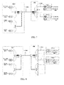
- FIG. 7 a schematic structural diagram of another WDM-PON system according to an embodiment of the present invention is shown.
- an OLT of a CO includes two AWGs, namely, AWG1 and AWG3.
- the AWG1 is configured to multiplex downlink data transmitted by each light emitter (LD1-LDn), and the AWG3 is configured to demultiplex an uplink optical signal from each ONU (ONU1-ONUn) and transmit the uplink optical signal to each light receiver Rx1-Rxn.
- the AWG3 is coupled to a trunk optical fiber through a circulator, and an FRM1 of the OLT is disposed between the circulator and the AWG1.
- the FRM1, the AWG1, and a gain medium in the light diode LD1-LDn form an ECL as described in the preceding embodiments.
- a working wavelength of the ECL can also automatically adapt to a wavelength of the port of the corresponding AWG1.
- FIG. 8 a schematic structural diagram of another WDM-PON system according to an embodiment of the present invention is shown.
- a structure of an OLT of a CO of the WDM-PON system shown in FIG. 8 is the same as that of the WDM-PON system shown in FIG. 7 , and a main improvement lies in a connection structure of an RN and an ONU at a user side.
- the RN includes two AWGs, namely, AWG2 and AWG4.
- the AWG2 is configured to multiplex uplink data transmitted by a light emitter LD of each ONU
- the AWG4 is configured to demultiplex a downlink optical signal from the OLT and transmit the downlink optical signal to a light receiver Rx of each ONU.
- the AWG4 is coupled to a trunk optical fiber through a circulator
- the RN further includes an FRM2, which is disposed between the circulator and the AWG2.
- the FRM2, the AWG2, and a gain medium in the light emitter LD of the ONU form an ECL as described in the preceding embodiments.
- a working wavelength of the ECL can also automatically adapt to a wavelength of the port of the corresponding AWG1.
- the present invention may be implemented by software plus necessary universal hardware, and definitely may also be implemented by hardware, but in most cases, the present invention is preferably implemented through the former method.
- the technical solutions of the present invention or the part that makes contributions to the prior art may be substantially embodied in the form of a software product.
- the computer software product is stored in a readable storage medium, for example, a floppy disk, hard disk, or optical disk of a computer, and include several instructions used to instruct computer equipment (for example, may be a personal computer, a server, or network equipment) to perform the method according to each embodiment of the present invention.
Landscapes
- Physics & Mathematics (AREA)
- Electromagnetism (AREA)
- Optics & Photonics (AREA)
- Condensed Matter Physics & Semiconductors (AREA)
- General Physics & Mathematics (AREA)
- Engineering & Computer Science (AREA)
- Computer Networks & Wireless Communication (AREA)
- Signal Processing (AREA)
- Computing Systems (AREA)
- Lasers (AREA)
- Optical Communication System (AREA)
- Semiconductor Lasers (AREA)
Applications Claiming Priority (2)
| Application Number | Priority Date | Filing Date | Title |
|---|---|---|---|
| CN2010105881182A CN102136674B (zh) | 2010-12-14 | 2010-12-14 | 外腔激光器和波分复用无源光网络系统 |
| PCT/CN2011/080595 WO2012079412A1 (fr) | 2010-12-14 | 2011-10-10 | Laser à cavité externe et système de réseau optique passif à multiplexage par division de longueur d'onde |
Publications (2)
| Publication Number | Publication Date |
|---|---|
| EP2637266A1 true EP2637266A1 (fr) | 2013-09-11 |
| EP2637266A4 EP2637266A4 (fr) | 2014-05-07 |
Family
ID=44296361
Family Applications (1)
| Application Number | Title | Priority Date | Filing Date |
|---|---|---|---|
| EP11849359.2A Withdrawn EP2637266A4 (fr) | 2010-12-14 | 2011-10-10 | Laser à cavité externe et système de réseau optique passif à multiplexage par division de longueur d'onde |
Country Status (7)
| Country | Link |
|---|---|
| US (1) | US20140205293A1 (fr) |
| EP (1) | EP2637266A4 (fr) |
| JP (1) | JP2014506394A (fr) |
| KR (1) | KR20130118347A (fr) |
| CN (1) | CN102136674B (fr) |
| TW (1) | TWI499148B (fr) |
| WO (1) | WO2012079412A1 (fr) |
Cited By (3)
| Publication number | Priority date | Publication date | Assignee | Title |
|---|---|---|---|---|
| WO2015176770A1 (fr) * | 2014-05-23 | 2015-11-26 | Telefonaktiebolaget L M Ericsson (Publ) | Source optique, appareil optique de réseau de communication et station de base de réseau de communication |
| EP3154211A4 (fr) * | 2014-03-13 | 2017-05-03 | Huawei Technologies Co., Ltd. | Procédé, dispositif et système pour adapter un paramètre d'émission de laser dans un wdm-pon |
| EP3402094A4 (fr) * | 2016-02-02 | 2019-02-13 | Huawei Technologies Co., Ltd. | Puce de multiplexeur optique réfléchissante, puce d'émetteur laser, et émetteur optique |
Families Citing this family (20)
| Publication number | Priority date | Publication date | Assignee | Title |
|---|---|---|---|---|
| US8774630B2 (en) * | 2010-10-15 | 2014-07-08 | Futurewei Technologies, Inc. | Method, apparatus, and system for a self-seeded external cavity laser for dense wavelength division multiplexing applications |
| CN102136674B (zh) * | 2010-12-14 | 2013-01-30 | 华为技术有限公司 | 外腔激光器和波分复用无源光网络系统 |
| CN102870352B (zh) * | 2012-06-25 | 2014-07-16 | 华为技术有限公司 | 一种光收发模块、光通信系统及光信号收发方法 |
| CN102870294B (zh) * | 2012-06-30 | 2014-06-25 | 华为技术有限公司 | 自注入激光器和无源光网络 |
| WO2014020618A1 (fr) | 2012-07-30 | 2014-02-06 | Oplink Communications, Inc. | Laser fabry-perot à cavité externe |
| WO2014022971A1 (fr) * | 2012-08-07 | 2014-02-13 | 华为技术有限公司 | Laser à modulation externe, appareil et système passif de communication optique |
| CN103634709B (zh) * | 2012-08-28 | 2018-01-12 | 上海诺基亚贝尔股份有限公司 | 用于支持光网络单元在多个无源光网络之间迁移的方法 |
| CN103098489B (zh) * | 2012-10-23 | 2015-11-25 | 华为技术有限公司 | 外腔激光器、光发射机及无源光网络系统 |
| WO2014075257A1 (fr) * | 2012-11-15 | 2014-05-22 | 华为技术有限公司 | Émetteur, procédé de génération d'un signal optique, dispositif et système |
| CN103199417A (zh) * | 2013-03-29 | 2013-07-10 | 武汉光迅科技股份有限公司 | 一种稀土掺杂光纤光源光路结构 |
| KR101844689B1 (ko) * | 2013-07-24 | 2018-04-02 | 후아웨이 테크놀러지 컴퍼니 리미티드 | 조정가능 광학 수신기, 조정가능 광학 송신기 및 조정가능 광학 송수신기 |
| US9455782B2 (en) * | 2014-08-11 | 2016-09-27 | Applied Optoelectronics, Inc. | Monitoring a multiplexed laser array in an optical communication system |
| CN107078795B (zh) * | 2014-09-03 | 2019-10-22 | 英国电讯有限公司 | 光网络节点、远程检测其电力状态的方法、电信网络 |
| EP3217682B1 (fr) | 2014-11-05 | 2019-07-31 | Huawei Technologies Co., Ltd. | Procédé de négociation automatique de port optique, module optique, dispositif côté bureau, et dispositif terminal |
| CN108604932B (zh) * | 2016-01-28 | 2020-08-07 | 华为技术有限公司 | 波长可调谐的光发射装置 |
| CN109782394A (zh) * | 2019-03-15 | 2019-05-21 | 杭州芯耘光电科技有限公司 | 一种单光纤双向光收发组件 |
| US11705694B1 (en) * | 2020-02-26 | 2023-07-18 | Cable Television Laboratories, Inc. | Systems and methods for optical injection-locking in an access network |
| WO2021257663A1 (fr) * | 2020-06-17 | 2021-12-23 | The Regents Of The University Of California | Laser à cavité intégrée à réseau sélectif planaire à bandes multiples de wdm athermique |
| CN119362126B (zh) * | 2024-10-22 | 2025-07-04 | 合肥脉锐光电技术有限公司 | 基于相位调制的高稳定自锁模光纤激光器 |
| CN119852827B (zh) * | 2025-01-02 | 2025-10-03 | 高迈光通讯技术(福建)有限公司 | 偏振edfa可调谐激光器 |
Family Cites Families (20)
| Publication number | Priority date | Publication date | Assignee | Title |
|---|---|---|---|---|
| JPS62149185A (ja) * | 1985-12-24 | 1987-07-03 | Fujitsu Ltd | 半導体レ−ザ装置 |
| JPS63186489A (ja) * | 1987-01-29 | 1988-08-02 | Yokogawa Electric Corp | 可変波長レ−ザ− |
| US5724373A (en) * | 1996-11-15 | 1998-03-03 | Hewlett-Packard Company | Microphotonic acousto-optic tunable laser |
| US6275317B1 (en) * | 1998-03-10 | 2001-08-14 | Agere Systems Optoelectronics Guardian Corp. | Hybrid integration of a wavelength selectable laser source and optical amplifier/modulator |
| JP2000012955A (ja) * | 1998-06-19 | 2000-01-14 | Yokogawa Electric Corp | 自己注入同期型半導体レーザ |
| US5949801A (en) * | 1998-07-22 | 1999-09-07 | Coretek, Inc. | Tunable laser and method for operating the same |
| US6339603B1 (en) * | 2000-10-25 | 2002-01-15 | Axsun Technologies, Inc. | Tunable laser with polarization anisotropic amplifier for fabry-perot filter reflection isolation |
| JP4059779B2 (ja) * | 2002-06-14 | 2008-03-12 | 富士通株式会社 | 波長選択装置、波長選択レーザおよび波長可変レーザ |
| JP2004112714A (ja) * | 2002-09-20 | 2004-04-08 | Ntt Electornics Corp | 波長多重送信装置 |
| KR100489922B1 (ko) * | 2002-10-01 | 2005-05-17 | 최준국 | 페브리-페롯 레이저 다이오드의 셀프 인젝션 락킹을이용한 고밀도 파장분할 다중방식 수동형 광가입자망 시스템 |
| US6993051B2 (en) * | 2003-08-12 | 2006-01-31 | Agilent Technologies, Inc. | External cavity tunable laser with provisions for intracavity optical reflection suppression |
| CN1545239A (zh) * | 2003-11-14 | 2004-11-10 | 清华大学 | 保持各路偏振态相同的光纤时分复用器装置 |
| KR100608946B1 (ko) * | 2004-10-20 | 2006-08-03 | 광주과학기술원 | 자체잠김된 페브리-페롯 레이저 다이오드를 이용한 파장분할다중 방식의 수동형 광통신망과, 이에 사용되는 지역 기지국 및 그 제어 방법 |
| CN101304156A (zh) * | 2008-06-05 | 2008-11-12 | 原辉 | 一种用于光纤光栅传感系统的外腔激光器装置 |
| US8417118B2 (en) * | 2009-08-14 | 2013-04-09 | Futurewei Technologies, Inc. | Colorless dense wavelength division multiplexing transmitters |
| CN102082610B (zh) * | 2009-12-01 | 2014-07-30 | 华为技术有限公司 | 自注入锁定光源、光源自注入锁定方法和系统 |
| US8559821B2 (en) * | 2009-12-02 | 2013-10-15 | Futurewei Technologies, Inc. | Wavelength stabilization and locking for colorless dense wavelength division multiplexing transmitters |
| CN103098390A (zh) * | 2010-09-16 | 2013-05-08 | 瑞典爱立信有限公司 | 无源光网络 |
| US8606107B2 (en) * | 2010-12-03 | 2013-12-10 | Futurewei Technologies, Inc. | Colorless dense wavelength division multiplexing transmitters |
| CN102136674B (zh) * | 2010-12-14 | 2013-01-30 | 华为技术有限公司 | 外腔激光器和波分复用无源光网络系统 |
-
2010
- 2010-12-14 CN CN2010105881182A patent/CN102136674B/zh active Active
-
2011
- 2011-10-10 JP JP2013543503A patent/JP2014506394A/ja active Pending
- 2011-10-10 WO PCT/CN2011/080595 patent/WO2012079412A1/fr not_active Ceased
- 2011-10-10 EP EP11849359.2A patent/EP2637266A4/fr not_active Withdrawn
- 2011-10-10 KR KR1020137015998A patent/KR20130118347A/ko not_active Ceased
- 2011-12-14 TW TW100146113A patent/TWI499148B/zh active
-
2013
- 2013-06-10 US US13/913,890 patent/US20140205293A1/en not_active Abandoned
Cited By (6)
| Publication number | Priority date | Publication date | Assignee | Title |
|---|---|---|---|---|
| EP3154211A4 (fr) * | 2014-03-13 | 2017-05-03 | Huawei Technologies Co., Ltd. | Procédé, dispositif et système pour adapter un paramètre d'émission de laser dans un wdm-pon |
| US9866318B2 (en) | 2014-03-13 | 2018-01-09 | Huawei Technologies Co., Ltd. | Method, apparatus, and system for adjusting emission parameter of laser in WDM-PON |
| WO2015176770A1 (fr) * | 2014-05-23 | 2015-11-26 | Telefonaktiebolaget L M Ericsson (Publ) | Source optique, appareil optique de réseau de communication et station de base de réseau de communication |
| US9806815B2 (en) | 2014-05-23 | 2017-10-31 | Telefonaktiebolaget Lm Ericsson (Publ) | Optical source, communications network optical apparatus and communications network base station |
| EP3402094A4 (fr) * | 2016-02-02 | 2019-02-13 | Huawei Technologies Co., Ltd. | Puce de multiplexeur optique réfléchissante, puce d'émetteur laser, et émetteur optique |
| US10841012B2 (en) | 2016-02-02 | 2020-11-17 | Huawei Technologies Co., Ltd. | Optical reflective multiplexer chip, laser transmitter chip, and optical transmitter |
Also Published As
| Publication number | Publication date |
|---|---|
| CN102136674A (zh) | 2011-07-27 |
| WO2012079412A1 (fr) | 2012-06-21 |
| KR20130118347A (ko) | 2013-10-29 |
| TWI499148B (zh) | 2015-09-01 |
| CN102136674B (zh) | 2013-01-30 |
| US20140205293A1 (en) | 2014-07-24 |
| EP2637266A4 (fr) | 2014-05-07 |
| JP2014506394A (ja) | 2014-03-13 |
| TW201234731A (en) | 2012-08-16 |
Similar Documents
| Publication | Publication Date | Title |
|---|---|---|
| EP2637266A1 (fr) | Laser à cavité externe et système de réseau optique passif à multiplexage par division de longueur d'onde | |
| US10009136B2 (en) | External cavity FP laser | |
| US8417118B2 (en) | Colorless dense wavelength division multiplexing transmitters | |
| CN102388547B (zh) | 自注入光收发模块和波分复用无源光网络系统 | |
| EP2507877B1 (fr) | Procédé et système de stabilization et verrouillage de la longueur d'onde pour émetteurs à multiplexage par division de longueur d'ondes | |
| US20140064733A1 (en) | Self-injection laser, wave division multiplexing passive optical network system and optical line terminal | |
| CN102143407B (zh) | 一种波分复用的无源光网络的传输方法、系统及装置 | |
| US9502858B2 (en) | Laser array mux assembly with external reflector for providing a selected wavelength or multiplexed wavelengths | |
| US20140185131A1 (en) | Multi-Wavelength Light Source Apparatus | |
| US9214790B2 (en) | Filtered laser array assembly with external optical modulation and WDM optical system including same | |
| TW201003272A (en) | Laser source based on fabry-perot laser diodes and seeding method using the same | |
| WO2011066775A1 (fr) | Source lumineuse à verrouillage par autoinjection, procédé et système pour le verrouillage d'une source lumineuse par auto-injection | |
| US9002214B2 (en) | Wavelength-selectable laser device and apparatus and system including same | |
| US8818208B2 (en) | Laser mux assembly for providing a selected wavelength | |
| EP4220870B1 (fr) | Puce laser, laser verrouillé par injection, et dispositif de réseau | |
| CN103229441B (zh) | 光模块及其突发发射方法、激光器及光网络系统 |
Legal Events
| Date | Code | Title | Description |
|---|---|---|---|
| PUAI | Public reference made under article 153(3) epc to a published international application that has entered the european phase |
Free format text: ORIGINAL CODE: 0009012 |
|
| 17P | Request for examination filed |
Effective date: 20130606 |
|
| AK | Designated contracting states |
Kind code of ref document: A1 Designated state(s): AL AT BE BG CH CY CZ DE DK EE ES FI FR GB GR HR HU IE IS IT LI LT LU LV MC MK MT NL NO PL PT RO RS SE SI SK SM TR |
|
| DAX | Request for extension of the european patent (deleted) | ||
| A4 | Supplementary search report drawn up and despatched |
Effective date: 20140409 |
|
| RIC1 | Information provided on ipc code assigned before grant |
Ipc: H01S 5/065 20060101ALN20140403BHEP Ipc: H04J 14/02 20060101ALI20140403BHEP Ipc: H04B 10/2587 20130101ALI20140403BHEP Ipc: H01S 5/14 20060101AFI20140403BHEP |
|
| RIN1 | Information on inventor provided before grant (corrected) |
Inventor name: PENG, GUIKAI Inventor name: LIN, HUAFENG Inventor name: XU, ZHIGUANG |
|
| STAA | Information on the status of an ep patent application or granted ep patent |
Free format text: STATUS: THE APPLICATION IS DEEMED TO BE WITHDRAWN |
|
| 18D | Application deemed to be withdrawn |
Effective date: 20141111 |