EP2637286A2 - Antrieb für ein Fenster oder dergleichen sowie ein Verfahren zur Montage des Antriebs - Google Patents
Antrieb für ein Fenster oder dergleichen sowie ein Verfahren zur Montage des Antriebs Download PDFInfo
- Publication number
- EP2637286A2 EP2637286A2 EP13158277.7A EP13158277A EP2637286A2 EP 2637286 A2 EP2637286 A2 EP 2637286A2 EP 13158277 A EP13158277 A EP 13158277A EP 2637286 A2 EP2637286 A2 EP 2637286A2
- Authority
- EP
- European Patent Office
- Prior art keywords
- board
- electric motor
- drive
- board holder
- housing
- Prior art date
- Legal status (The legal status is an assumption and is not a legal conclusion. Google has not performed a legal analysis and makes no representation as to the accuracy of the status listed.)
- Granted
Links
Images

Classifications
-
- H—ELECTRICITY
- H02—GENERATION; CONVERSION OR DISTRIBUTION OF ELECTRIC POWER
- H02K—DYNAMO-ELECTRIC MACHINES
- H02K7/00—Arrangements for handling mechanical energy structurally associated with dynamo-electric machines, e.g. structural association with mechanical driving motors or auxiliary dynamo-electric machines
- H02K7/14—Structural association with mechanical loads, e.g. with hand-held machine tools or fans
-
- E—FIXED CONSTRUCTIONS
- E05—LOCKS; KEYS; WINDOW OR DOOR FITTINGS; SAFES
- E05F—DEVICES FOR MOVING WINGS INTO OPEN OR CLOSED POSITION; CHECKS FOR WINGS; WING FITTINGS NOT OTHERWISE PROVIDED FOR, CONCERNED WITH THE FUNCTIONING OF THE WING
- E05F15/00—Power-operated mechanisms for wings
- E05F15/60—Power-operated mechanisms for wings using electrical actuators
- E05F15/603—Power-operated mechanisms for wings using electrical actuators using rotary electromotors
-
- H—ELECTRICITY
- H02—GENERATION; CONVERSION OR DISTRIBUTION OF ELECTRIC POWER
- H02K—DYNAMO-ELECTRIC MACHINES
- H02K11/00—Structural association of dynamo-electric machines with electric components or with devices for shielding, monitoring or protection
- H02K11/30—Structural association with control circuits or drive circuits
-
- E—FIXED CONSTRUCTIONS
- E05—LOCKS; KEYS; WINDOW OR DOOR FITTINGS; SAFES
- E05Y—INDEXING SCHEME ASSOCIATED WITH SUBCLASSES E05D AND E05F, RELATING TO CONSTRUCTION ELEMENTS, ELECTRIC CONTROL, POWER SUPPLY, POWER SIGNAL OR TRANSMISSION, USER INTERFACES, MOUNTING OR COUPLING, DETAILS, ACCESSORIES, AUXILIARY OPERATIONS NOT OTHERWISE PROVIDED FOR, APPLICATION THEREOF
- E05Y2600/00—Mounting or coupling arrangements for elements provided for in this subclass
- E05Y2600/60—Mounting or coupling members; Accessories therefor
- E05Y2600/626—Plates or brackets
-
- E—FIXED CONSTRUCTIONS
- E05—LOCKS; KEYS; WINDOW OR DOOR FITTINGS; SAFES
- E05Y—INDEXING SCHEME ASSOCIATED WITH SUBCLASSES E05D AND E05F, RELATING TO CONSTRUCTION ELEMENTS, ELECTRIC CONTROL, POWER SUPPLY, POWER SIGNAL OR TRANSMISSION, USER INTERFACES, MOUNTING OR COUPLING, DETAILS, ACCESSORIES, AUXILIARY OPERATIONS NOT OTHERWISE PROVIDED FOR, APPLICATION THEREOF
- E05Y2600/00—Mounting or coupling arrangements for elements provided for in this subclass
- E05Y2600/60—Mounting or coupling members; Accessories therefor
- E05Y2600/63—Retainers
-
- H—ELECTRICITY
- H02—GENERATION; CONVERSION OR DISTRIBUTION OF ELECTRIC POWER
- H02K—DYNAMO-ELECTRIC MACHINES
- H02K2207/00—Specific aspects not provided for in the other groups of this subclass relating to arrangements for handling mechanical energy
- H02K2207/03—Tubular motors, i.e. rotary motors mounted inside a tube, e.g. for blinds
Definitions
- the invention relates to a drive for a window or the like according to the preamble of claim 1 and a method for assembling the drive according to claim 10.
- the DE 196 17 083 A1 discloses a drive for a door, a window or the like, with arranged in a housing of the drive electric motor and an associated circuit board with an electronic circuit arrangement.
- a drive for a wing of a window with an electric drive motor which drives a drive spindle for moving the wing of the window.
- a load shutdown is arranged as an electronic circuit on a circuit board, which is fixed to an end cap of the housing.
- the invention has for its object to provide a drive with a simple and reliable arrangement of an electronic circuit in the drive and with a simple assembly.
- Drives for wing of windows are provided in a conventional manner for pivoting the wing between an open position and a closed position of the wing.
- the drive can for example be designed as a spindle drive and is mounted with a bracket alternatively on the wing or a frame surrounding the wing pivotally.
- the arrangement according to the invention can also find application in other drives, such as a chain drive or a locking drive.
- the drive comprises a housing in which an output element, for example a spindle, a chain or thrust element, is arranged, which can be actuated by an electric motor.
- the drive has an electronic circuit arrangement arranged on a printed circuit board, which is advantageously arranged simply and reliably in a circuit board holder.
- the board holder has at one end an end plate, which secures the otherwise cylindrical board holder in the housing of the drive against rotation and which serves as an abutment on an end cap, which closes the housing frontally and is provided for carrying a connecting line.
- On the front plate are recesses for a connector of the connecting cable or for access to adjustment elements, such as a rotary switch or DIP switches, which are provided for selecting parameters of the drive.
- a receiving ring is formed at the other end of the face plate, which is designed to be received on the electric motor.
- the receiving ring is provided with slots which divides the receiving ring into segments, whereby the segments are elastically resilient.
- the system lugs limit the insertion depth of the electric motor by coming into contact with the front side of the electric motor.
- opposite guide grooves are provided, which are advantageously deepened in their course by both sides of the guide groove arranged webs for safe guidance of the board.
- an L-shaped recess is provided on both sides, whereby an elastically resilient web is formed. Since in each case one of the guide grooves for the board is arranged on the inside of these spring webs, the board is fixed by clamping when inserted into the guide grooves in the end. The tension of the spring bars by the material thickness and the formation of the L-shaped recess is constructively chosen so that the board can be inserted easily, but is also sufficiently secured by the clamping.
- the board holder allows easy and reliable installation of the drive. After inserting the board in the guide groove of the board holder and complete insertion, the board is already safely included in the board holder. Subsequently, the attachment of the board holder takes place with the board on the electric motor, whereby an exact connection to the electric motor is made. After contacting the connection line and optionally selecting or changing parameters of the drive, as far as they were not already set before inserting the board, the drive is completed by attaching the end cap to the housing.
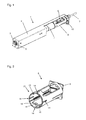
- a drive 1 for a wing of a window not shown here is shown, which is provided in a conventional manner for pivoting the wing between an open position and a closed position of the wing.
- the drive 1 is formed here as a spindle drive and, not shown here, be mounted with a bracket alternatively on the wing or a frame surrounding the wing pivotally.
- the drive 1 has a housing 2, in which a spindle 3 is mounted, which is drivable by means of an electric motor 4.
- the spindle 3 is surrounded by a provided with a spindle nut push rod 5, which, depending on the mounting manner of the drive 1 on the window frame or on the wing is pivotally supported.
- the drive 1 also has an electronic circuit arrangement, which is located on a circuit board 6, on which also the connection of the drive 1 takes place by means of the connection line 7.
- the circuit board 6 is advantageously arranged simply and reliably in a circuit board holder 8.
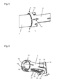
- the board holder 8 is shown as an individual part without inserted board 6.
- the board holder 8 has a front side substantially the inner dimensions of the housing 2 adapted end plate 9, which secures the otherwise cylindrical board holder 8 in its position against rotation.
- the front plate 9 may further be provided for abutment of the board holder 8 on an end cap 10, which is fixed to the housing 2 and through which the connecting line 7 is guided.
- the front plate 9 has a rectangular recess 11 for the passage of a connector for the connecting line 7 and a circular recess 12, which allows access to a rotary switch on the board 6, for selecting parameters of the drive 1, such as the stroke of the push rod 5, is provided.
- a receiving ring 13 for the coupling of the electric motor 4 is provided at the other end opposite to the front plate 9, which includes the electric motor 4, as in the Fig. 4 and 5 is shown.
- slots 14 are arranged, which divides the receiving ring 13 into segments which are elastically resilient due to the slots 14.
- 13 bearing lugs 15 and locking lugs 16 are provided on the receiving ring, which correspond with locking recesses 17 on the electric motor 4.
- Each segment advantageously has an abutment nose 15 and a detent 16.
- Fig. 5 shows the electric motor 4 connected to the board holder 8.
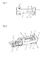
- a guide groove 18 is provided in the board holder 8 opposite each other, which is recessed in its course by both sides of the guide groove 18 arranged webs 19 to ensure reliable support of the board 6, as shown in the Fig. 6 to 8 is shown.
- the board holder 8 advantageously has an L-shaped recess 20 on both sides, which extends with its long leg 21 approximately from the middle of the longitudinal extension of the board holder 8 through to the front plate 9 and the short Leg 22 extends at right angles to the long leg 21 in parallel along the end plate 9.
- the resulting spring bar 23, on whose inner side the guide groove 18 is arranged can elastically deform.
- the spring bar 23 springs in the region of the corner at the transition of the long leg 21 to the short leg 22, as in the Fig. 6 , Distance A is shown.
- the distance of the guide grooves 18 is dimensioned in the region of the receiving ring 13 so that it is slightly larger than the width of the board 6, so that they can be easily inserted and inserted into the board holder 8 initially. In the region of the spring webs 23, the distance of the guide grooves 18 is smaller, so that the board 6 spreads the resilient spring webs 23 during insertion, whereby the board 6 is received in the guide grooves 18 secured by the clamping action.
- the circuit board 6 is electrically securely received spaced from the housing 2.
- the assembly of the drive 1 can be done easily and reliably by the board holder 8.
- the board 6 is inserted into the board holder 8 in the guide groove 18 and secured by full insertion to the face plate 9.
- the circuit board 6 is pushed so far with the board holder 8 on the front side of the electric motor 4 that the electric motor 4 is locked to the board holder 8, after which the unit is inserted into the housing 2 of the drive 1.
- contact pins may be arranged on the electric motor 4, which pins engage in associated sockets on the board 6.
- a corresponding connection via connecting wires and a plug connection can be made.
- the end cap 10 with the connecting line 7 is brought to the front plate 9 of the board holder 8 and contacted the connecting line 7 by means of connectors through the recess 11 with the board 6. Furthermore, settings on the selector switch arranged on the board, which is accessible through the recess 12, can also be carried out. Finally, by inserting and fixing the end cap 10 on the housing 2, the completion of the drive. 1
Landscapes
- Engineering & Computer Science (AREA)
- Power Engineering (AREA)
- Power-Operated Mechanisms For Wings (AREA)
- Motor Or Generator Frames (AREA)
- Window Of Vehicle (AREA)
Abstract
Description
- Die Erfindung betrifft einen Antrieb für ein Fenster oder dergleichen nach dem Oberbegriff des Anspruchs 1 sowie ein Verfahren zur Montage des Antriebs nach Anspruch 10.
- Die
DE 196 17 083 A1 offenbart einen Antrieb für eine Tür, ein Fenster oder dergleichen, mit in einem Gehäuse des Antriebs angeordnetem Elektromotor sowie einer zugeordneten Platine mit einer elektronischen Schaltungsanordnung. - Die Anordnung und Festlegung der Platine in dem Gehäuse des Antriebs sind nicht gezeigt.
- Aus der
DE 195 14 229 A1 ist ein Antrieb für einen Flügel eines Fensters bekannt, mit einem elektrischen Antriebsmotor, welcher eine Antriebsspindel zum Bewegen des Flügels des Fensters antreibt. Im Antriebsgehäuse ist eine Lastabschaltung als elektronische Schaltung auf einer Platine angeordnet, welche an einer Endkappe des Gehäuses fixiert ist. - Größere Platinen sind möglicherweise nicht ausreichend in dem Gehäuse gesichert, so dass es zu einer Berührung leitender Bauteile mit dem Gehäuse kommen könnte.
- Der Erfindung liegt die Aufgabe zugrunde, einen Antrieb mit einer einfachen und zuverlässigen Anordnung einer elektronischen Schaltung in dem Antrieb und mit einer einfachen Montage zu schaffen.
- Die Aufgabe wird durch die Merkmale des Anspruchs 1 sowie des Anspruchs 10 gelöst.
- Die Unteransprüche bilden vorteilhafte Ausgestaltungsmöglichkeiten der Erfindung.
- Antriebe für Flügel von Fenstern sind in an sich bekannter Weise zum Schwenken des Flügels zwischen einer Offenstellung und einer Geschlossenstellung des Flügels vorgesehen. Der Antrieb kann beispielsweise als Spindelantrieb ausgebildet sein und ist mit einer Konsole alternativ am Flügel oder einem den Flügel umgebenden Blendrahmen schwenkbeweglich gelagert. Die erfindungsgemäße Anordnung kann jedoch auch bei anderen Antrieben, wie einem Kettenantrieb oder einem Verrieglungsantrieb, Anwendung finden.
- Der Antrieb umfasst ein Gehäuse, in dem ein Abtriebselement, beispielsweise eine Spindel, eine Kette oder Schubelement, angeordnet ist, das mit einem Elektromotor betätigbar ist. Der Antrieb weist eine auf einer Platine angeordnete elektronische Schaltungsanordnung auf, die vorteilhaft einfach und zuverlässig in einem Platinenhalter angeordnet ist.
- Der Platinenhalter weist einerends eine Stirnplatte auf, welche den ansonsten zylindrischen Platinenhalter in dem Gehäuse des Antriebs gegen Verdrehen sichert und die als Anlage an einer Endkappe dient, welche das Gehäuse stirnseitig verschließt und zur Durchführung einer Anschlussleitung vorgesehen ist. An der Stirnplatte sind Aussparungen für einen Steckverbinder der Anschlussleitung oder für den Zugriff auf Einstellelemente, beispielsweise einen Drehschalter oder DIP-Schalter, die zur Auswahl von Parametern des Antriebs vorgesehen sind.
- Am zylindrischen Teil des Platinenhalters ist andernends gegenüber der Stirnplatte ein Aufnahmering ausgebildet, welcher zur Aufnahme am Elektromotor ausgebildet ist. Der Aufnahmering ist mit Schlitzen versehen, welche den Aufnahmering in Segmente unterteilt, wodurch die Segmente elastisch federnd sind. Es sind am Aufnahmering Anlagenasen sowie Rastnasen angeordnet, wobei die Rastnasen mit Rastausnehmungen am Elektromotor korrespondieren. Die Anlagenasen begrenzen die Einschubtiefe des Elektromotors, indem diese mit der Stirnseite des Elektromotors in Anlage kommen. Vorteilhaft besteht so ein definierter Abstand des Elektromotors zu der im Platinenhalter angeordneten Platine, so dass vorgesehene Sensoren, beispielsweise für eine Drehzahlerfassung, aus der sich eine Position des Abtriebselements ermitteln lässt, korrespondierend anordenbar sind.
- Zur Anordnung der Platine im Platinenhalter sind einander gegenüberliegende Führungsnuten vorgesehen, welche vorteilhaft in ihrem Verlauf durch beiderseits der Führungsnut angeordnete Stege zur sicheren Führung der Platine vertieft sind. Am Platinenhalter ist beidseitig eine L-förmige Ausnehmung vorgesehen, wodurch ein elastisch federnder Steg gebildet ist. Da auf Innenseite dieser Federstege jeweils eine der Führungsnuten für die Platine angeordnet ist, wird die Platine beim Einschieben in die Führungsnuten in deren Endbereich durch Klemmung fixiert. Dabei ist die Spannung der Federstege durch die Materialstärke und die Ausbildung der L-förmigen Ausnehmung konstruktiv so gewählt, dass sich die Platine problemlos einschieben lässt, jedoch auch ausreichend durch die Klemmung gesichert ist.
- Der Platinenhalter ermöglicht eine einfache und zuverlässige Montage des Antriebs. Nach Einsetzen der Platine in die Führungsnut des Platinenhalters und vollständigem Einschieben ist die Platine bereits sicher im Platinenhalter aufgenommen. Anschließend erfolgt das Aufstecken des Platinenhalters mit der Platine auf den Elektromotor, wodurch eine exakte Verbindung zum Elektromotor hergestellt wird. Nach Kontaktieren der Anschlussleitung und gegebenenfalls der Auswahl bzw. Änderung von Parametern des Antriebs, soweit diese nicht bereits vor Einsetzen der Platine eingestellt wurden, wird der Antrieb durch Befestigen der Endkappe am Gehäuse fertiggestellt.
- Im Nachfolgenden wird ein Ausführungsbeispiel in der Zeichnung anhand der Figuren näher erläutert.
- Dabei zeigen:
- Fig. 1
- einen Antrieb mit teilweise geschnittenem Gehäuse im Bereich des Elektromotors und des Platinenhalters;
- Fig. 2
- den Platinenhalter in einer ersten Ansicht im Schrägbild;
- Fig. 3
- eine weitere Ansicht des Platinenhalters gemäß
Fig. 2 im Schrägbild; - Fig. 4
- einen Ausschnitt des Platinenhalters und des Elektromotors des Antriebs gemäß
Fig. 1 ; - Fig. 5
- einen Ausschnitt des Platinenhalters und des Elektromotors gemäß
Fig. 4 wobei der Platinenhalter auf den Elektromotor aufgesteckt ist; - Fig. 6
- eine weitere Ansicht des Platinenhalters gemäß
Fig. 2 im Schrägbild; - Fig. 7
- eine Seitenansicht des Platinenhalters gemäß
Fig. 2 ; - Fig. 8
- eine Ansicht auf den Platinenhalter mit teilweise eingeschobener Platine im Schrägbild.
- In
Fig. 1 ist ein Antrieb 1 für einen Flügel eines hier nicht weiter dargestellten Fensters gezeigt, der in an sich bekannter Weise zum Schwenken des Flügels zwischen einer Offenstellung und einer Geschlossenstellung des Flügels vorgesehen ist. Der Antrieb 1 ist hier als Spindelantrieb ausgebildet und kann, hier nicht dargestellt, mit einer Konsole alternativ am Flügel oder einem den Flügel umgebenden Blendrahmen schwenkbeweglich gelagert sein. - Der Antrieb 1 weist ein Gehäuse 2 auf, in dem eine Spindel 3 gelagert ist, welche mittels eines Elektromotors 4 antreibbar ist. Die Spindel 3 ist von einer mit einer Spindelmutter versehenen Schubstange 5 umgeben, welcher, je nach Montageweise des Antriebs 1 am Blendrahmen oder am Flügel schwenkbeweglich abgestützt ist.
- Der Antrieb 1 weist weiterhin eine elektronische Schaltungsanordnung auf, die sich auf einer Platine 6 befindet, an welcher auch der Anschluss des Antriebs 1 mittels der Anschlussleitung 7 erfolgt. Die Platine 6 ist vorteilhaft einfach und zuverlässig in einem Platinenhalter 8 angeordnet.
- In den
Fig. 2 ,3 und6 ist der Platinenhalter 8 als Einzelteil ohne eingesetzte Platine 6 gezeigt. Einerends weist der Platinenhalter 8 stirnseitig eine im Wesentlichen den inneren Abmessungen des Gehäuses 2 angepasste Stirnplatte 9 auf, welche den ansonsten zylindrischen Platinenhalter 8 in seiner Lage gegen Verdrehen sichert. Die Stirnplatte 9 kann weiterhin zur Anlage des Platinenhalters 8 an einer Endkappe 10 vorgesehen sein, welche am Gehäuse 2 festgelegt ist und durch welche die Anschlussleitung 7 geführt ist. Die Stirnplatte 9 weist eine rechteckige Aussparung 11 für den Durchgriff einer Steckverbindung für die Anschlussleitung 7 und eine runde Aussparung 12 auf, welche den Zugriff auf einen Drehschalter auf der Platine 6 ermöglicht, der zur Auswahl von Parametern des Antriebs 1, wie den Hub der Schubstange 5, vorgesehen ist. - Am zylindrischen Teil des Platinenhalters 8 ist andernends gegenüber der Stirnplatte 9 ein Aufnahmering 13 für die Ankopplung des Elektromotors 4 vorgesehen, welcher den Elektromotor 4 umfasst, wie es in den
Fig. 4 und5 gezeigt ist. Am Aufnahmering 13 sind Schlitze 14 angeordnet, welche den Aufnahmering 13 in Segmente unterteilt, welche aufgrund der Schlitze 14 elastisch federnd sind. Weiterhin sind am Aufnahmering 13 Anlagenasen 15 sowie Rastnasen 16 vorgesehen, welche mit Rastausnehmungen 17 am Elektromotor 4 korrespondieren. Jedes Segment weist vorteilhaft eine Anlagenase 15 und eine Rastnase 16 auf.Fig. 5 zeigt den mit dem Platinenhalter 8 verbundenen Elektromotor 4. - Vorteilhaft besteht durch die Anlagenasen 15 eine definierte Lage zum Elektromotor 4, so dass beispielsweise ein auf der Welle des Elektromotors 4 angebrachter Magnet direkt mit der auf der Platine 6 angeordneten Schaltungsanordnung einen Inkrementalgeber bilden kann, wodurch die Position der Schubstange 5 und somit die Stellung des Flügels des Fensters erfassbar ist.
- Zur Anordnung der Platine 6 ist im Platinenhalter 8 einander gegenüberliegend jeweils eine Führungsnut 18 vorgesehen, welche in ihrem Verlauf durch beiderseits der Führungsnut 18 angeordnete Stege 19 vertieft ist, um eine zuverlässige Abstützung der Platine 6 zu gewährleisten, wie es in den
Fig. 6 bis 8 gezeigt ist. Der Platinenhalter 8 weist vorteilhaft beidseitig eine L-förmige Ausnehmung 20 auf, welche sich mit ihrem langen Schenkel 21 etwa ab der Mitte der Längserstreckung des Platinenhalters 8 bis hin zur Stirnplatte 9 hin erstreckt und deren kurzer Schenkel 22 sich im rechten Winkel zum langen Schenkel 21 parallel entlang der Stirnplatte 9 erstreckt. Konstruktiv bedingt kann sich so der entstandene Federsteg 23, auf dessen Innenseite die Führungsnut 18 angeordnet ist, elastisch verformen. Insbesondere federt der Federsteg 23 im Bereich der Ecke am Übergang des langen Schenkels 21 zum kurzen Schenkel 22, wie es in derFig. 6 , Abstand A gezeigt ist. - Der Abstand der Führungsnuten 18 ist im Bereich des Aufnahmerings 13 so dimensioniert, dass dieser etwas größer ist als die Breite der Platine 6, so dass sich diese anfänglich leicht in den Platinenhalter 8 einsetzen und einschieben lässt. Im Bereich der Federstege 23 ist der Abstand der Führungsnuten 18 geringer, so dass die Platine 6 die elastisch federnden Federstege 23 beim Einschieben spreizt, wodurch die Platine 6 in den Führungsnuten 18 durch die Klemmwirkung gesichert aufgenommen ist. Die Platine 6 ist elektrisch sicher vom Gehäuse 2 beabstandet aufgenommen.
- Die Montage des Antriebs 1 kann durch den Platinenhalter 8 einfach und zuverlässig erfolgen. Zunächst wird die Platine 6 in den Platinenhalter 8 in die Führungsnut 18 eingesetzt und durch vollständiges Einschieben bis zur Stirnplatte 9 gesichert. Sodann wird die Platine 6 mit dem Platinenhalter 8 stirnseitig auf den Elektromotor 4 so weit aufgeschoben, dass der Elektromotor 4 mit dem Platinenhalter 8 verrastet, wonach die Einheit in das Gehäuse 2 des Antriebs 1 eingeführt wird. Zur Herstellung der elektrischen Verbindung können dabei am Elektromotor 4 Kontaktstifte angeordnet sein, welche in zugeordnete Buchsen auf der Platine 6 eingreifen. Alternativ kann auch eine entsprechende Verbindung über Anschlussdrähte und eine Steckverbindung hergestellt werden. Die Endkappe 10 mit der Anschlussleitung 7 wird an die Stirnplatte 9 des Platinenhalters 8 herangeführt und die Anschlussleitung 7 mittels Steckverbinder durch die Aussparung 11 mit der Platine 6 kontaktiert. Weiterhin können auch noch Einstellungen am auf der Platine angeordneten Wahlschalter, welcher durch die Aussparung 12 zugänglich ist, durchgeführt werden. Zuletzt erfolgt durch Einsetzen und Festlegen der Endkappe 10 am Gehäuse 2 die Fertigstellung des Antriebs 1.
-
1 Antrieb 2 Gehäuse 3 Spindel 4 Elektromotor 5 Schubstange 6 Platine 7 Anschlussleitung 8 Platinenhalter 9 Stirnplatte 10 Endkappe 11 Aussparung 12 Aussparung 13 Aufnahmering 14 Schlitz 15 Anlagenase 16 Rastnase 17 Rastausnehmung 18 Führungsnut 19 Steg 20 Ausnehmung 21 Schenkel 22 Schenkel 23 Federsteg
Claims (10)
- Antrieb (1) für ein Fenster oder dergleichen, mit in einem Gehäuse (2), mit einem in dem Gehäuse (2) angeordneten Elektromotor (4) sowie mit einer zugeordneten Platine (6) mit einer elektronischen Schaltungsanordnung,
dadurch gekennzeichnet,
dass die Platine (6) in einem Platinenhalter (8) angeordnet ist, wobei der Platinenhalter (8) auf den Elektromotor (4) aufgesteckt ist und sich zwischen dem Elektromotor (4) und einer Endkappe (10) erstreckt. - Antrieb nach Anspruch 1,
dadurch gekennzeichnet, dass der Platinenhalter (8) einen Aufnahmering (13) aufweist, welcher zur Ankopplung des Elektromotors (4) den Elektromotor (4) umfasst. - Antrieb nach Anspruch 2,
dadurch gekennzeichnet, dass am Aufnahmering (13) Schlitze (14) angeordnet sind, welche den Aufnahmering (13) in elastisch federnde Segmente unterteilen. - Antrieb nach einem der Ansprüche 2 oder 3,
dadurch gekennzeichnet, dass am Aufnahmering (13) Rastnasen (16) vorgesehen sind, welche mit Rastausnehmungen (17) am Elektromotor (4) zur Ankopplung des Elektromotors (4) korrespondieren. - Antrieb nach einem der Ansprüche 3 oder 4,
dadurch gekennzeichnet, dass wenigstens ein Segment mindestens eine Anlagenase (15) und/oder mindestens eine Rastnase (16) aufweist. - Antrieb nach Anspruch 1,
dadurch gekennzeichnet, dass im Platinenhalter (8) einander gegenüberliegend jeweils eine Führungsnut (18) zur Anordnung der Platine (6) vorgesehen ist. - Antrieb nach Anspruch 6,
dadurch gekennzeichnet, dass die Führungsnut (18) durch beiderseits der Führungsnut (18) angeordnete Stege (19) zur Abstützung der Platine (6) vertieft ist. - Antrieb nach Anspruch 1,
dadurch gekennzeichnet, dass eine Ausnehmung (20) mit einem ersten Schenkel (21) und einem zweiten Schenkel (22) einen Federsteg (23) am Platinenhalter (8) bildet. - Antrieb nach Anspruch 8,
dadurch gekennzeichnet, dass eine Führungsnut (18) auf der Innenseite jedes Federstegs (23) angeordnet ist, so dass die Platine (6) die Federstege (23) beim Einschieben elastisch spreizt. - Verfahren zur Montage eines Antriebs nach Anspruch 1, gekennzeichnet durch,- Einsetzen der Platine (6) in die Führungsnuten (18) des Platinenhalters (8);- vollständiges Einschieben der Platine (6) in den Platinenhalter (8) unter Aufspreizen der Federstege (23);- Aufschieben des Aufnahmerings (13) des Platinenhalters (8) auf den Elektromotor (4) und Einrasten der Rastnasen (16) des Aufnahmerings (13) mit den Rastausnehmungen (17) des Elektromotors (4);- Einführen in das Gehäuse (2) des Antriebs (1);- Heranführen der Endkappe (10) mit der Anschlussleitung (7) an das Gehäuse (2) und Kontaktieren der Anschlussleitung (7) mit der Platine (6);- Einsetzen und Festlegen der Endkappe (10) am Gehäuse (2) des Antriebs (1).
Applications Claiming Priority (1)
| Application Number | Priority Date | Filing Date | Title |
|---|---|---|---|
| DE102012203735.7A DE102012203735C5 (de) | 2012-03-09 | 2012-03-09 | Antrieb für ein Fenster oder dergleichen sowie ein Verfahren zur Montage des Antriebs |
Publications (3)
| Publication Number | Publication Date |
|---|---|
| EP2637286A2 true EP2637286A2 (de) | 2013-09-11 |
| EP2637286A3 EP2637286A3 (de) | 2017-08-30 |
| EP2637286B1 EP2637286B1 (de) | 2020-09-30 |
Family
ID=47845781
Family Applications (1)
| Application Number | Title | Priority Date | Filing Date |
|---|---|---|---|
| EP13158277.7A Active EP2637286B1 (de) | 2012-03-09 | 2013-03-08 | Antrieb für ein Fenster oder dergleichen sowie ein Verfahren zur Montage des Antriebs |
Country Status (2)
| Country | Link |
|---|---|
| EP (1) | EP2637286B1 (de) |
| DE (1) | DE102012203735C5 (de) |
Cited By (2)
| Publication number | Priority date | Publication date | Assignee | Title |
|---|---|---|---|---|
| EP3015632A1 (de) * | 2014-10-31 | 2016-05-04 | DORMA Deutschland GmbH | Türantrieb |
| EP3757329A1 (de) * | 2019-06-27 | 2020-12-30 | GEZE GmbH | Gehäuse für einen antrieb sowie antrieb |
Families Citing this family (1)
| Publication number | Priority date | Publication date | Assignee | Title |
|---|---|---|---|---|
| DE102024126174A1 (de) * | 2024-09-11 | 2026-03-12 | Edscha Mechatronics Solutions GmbH | Antriebseinheit, temporäre Haltevorrichtung und Herstellungsverfahren |
Citations (2)
| Publication number | Priority date | Publication date | Assignee | Title |
|---|---|---|---|---|
| DE19514229A1 (de) | 1995-04-15 | 1996-10-17 | Geze Gmbh & Co | Lastabschaltvorrichtung |
| DE19617083A1 (de) | 1996-04-29 | 1997-10-30 | Geze Gmbh & Co | Antriebsvorrichtung für den Flügel eines Fensters, einer Tür oder dergleichen |
Family Cites Families (22)
| Publication number | Priority date | Publication date | Assignee | Title |
|---|---|---|---|---|
| DE4209823A1 (de) * | 1992-03-26 | 1993-09-30 | Kienzle Uhrenfabriken Gmbh | Schrittmotor |
| NL1001829C2 (nl) * | 1995-12-06 | 1997-06-10 | Nedap Nv | Schuifdakbesturing in combinatie met motor en Hall-effect sensor. |
| DE19851455A1 (de) * | 1998-02-05 | 1999-08-12 | Bosch Gmbh Robert | Elektronikmodul für eine elektromotorisch betriebene Antriebseinheit |
| JP3600860B2 (ja) * | 2000-11-22 | 2004-12-15 | 伊東電機株式会社 | モータ内蔵ローラ及びモータ内蔵ローラ用のユニット |
| DE20221581U1 (de) * | 2002-04-09 | 2006-06-08 | Vkr Holding A/S | Kompaktes Betätigungselement |
| DE20312402U1 (de) * | 2003-08-07 | 2004-12-23 | Aumüller Aumatic GmbH | Betätigungseinrichtung |
| DE202004020163U1 (de) * | 2004-12-23 | 2006-05-04 | Aumüller Aumatic GmbH | Betätigungseinrichtung für bewegliche Teile |
| SE529217C2 (sv) * | 2005-05-20 | 2007-06-05 | Atlas Copco Tools Ab | Momentberoende utlösningskoppling för en skruvdragare |
| FR2891414B1 (fr) * | 2005-09-28 | 2007-12-21 | Fp2X Groupement D Interet Econ | Dispositif de moteur electrique tubulaire. |
| WO2008019818A1 (de) * | 2006-08-14 | 2008-02-21 | Grundfos Management A/S | Statoranordnung für ein pumpenaggregat |
| DE102006041689A1 (de) * | 2006-08-28 | 2008-03-20 | Alfred Schellenberg Gmbh | Rohrförmige Antriebsvorrichtung zum Auf- und Abwickeln einer Verdunkelungsvorrichtung, insbesondere eines Rollladens o.dgl. |
| DE102006049635A1 (de) * | 2006-10-20 | 2008-04-30 | Siemens Ag | Steuereinheit zum Steuern einer elektromotorischen Antriebseinheit |
| DE202006017302U1 (de) * | 2006-11-10 | 2007-01-04 | D + H Mechatronic Ag | Betätigungsvorrichtung für bewegliche Gebäudeteile, insbesondere schwenkbare Fenster oder Klappen |
| ATE505651T1 (de) * | 2007-01-18 | 2011-04-15 | Grundfos Management As | Pumpenaggregat |
| DE102007022070A1 (de) * | 2007-05-08 | 2008-11-13 | Wilo Ag | Elektromotor |
| DE202007018840U1 (de) * | 2007-08-28 | 2009-08-06 | Deutsche Vortex Gmbh & Co. Kg | Steuerung zum Ein- und Ausschalten einer Zirkulationspumpe einer Warmwasserversorgung |
| DE102007054460A1 (de) * | 2007-11-13 | 2009-05-14 | Dorma Gmbh + Co. Kg | Türantrieb mit modularem Aufbau |
| DE102008008743B4 (de) * | 2008-02-12 | 2011-04-14 | Stabilus Gmbh | Antriebseinrichtung |
| DE202009014334U1 (de) * | 2009-10-23 | 2011-02-24 | Marantec Antriebs- Und Steuerungstechnik Gmbh & Co. Kg | Trafovorrichtung für Torantrieb und Torantrieb |
| EP2499320A1 (de) * | 2009-11-13 | 2012-09-19 | Dorma GmbH + Co. KG | Verkleidung für einen türbetätiger |
| DE102010051918A1 (de) * | 2010-11-11 | 2012-05-16 | Deutsche Vortex Gmbh & Co. Kg | Gehäusekappe, Gehäusekappeneinrichtung und Gehäuse für eine Zirkulationspumpe |
| DE102010053225A1 (de) * | 2010-12-03 | 2012-06-06 | Stabilus Gmbh | Antriebseinrichtung |
-
2012
- 2012-03-09 DE DE102012203735.7A patent/DE102012203735C5/de active Active
-
2013
- 2013-03-08 EP EP13158277.7A patent/EP2637286B1/de active Active
Patent Citations (2)
| Publication number | Priority date | Publication date | Assignee | Title |
|---|---|---|---|---|
| DE19514229A1 (de) | 1995-04-15 | 1996-10-17 | Geze Gmbh & Co | Lastabschaltvorrichtung |
| DE19617083A1 (de) | 1996-04-29 | 1997-10-30 | Geze Gmbh & Co | Antriebsvorrichtung für den Flügel eines Fensters, einer Tür oder dergleichen |
Cited By (2)
| Publication number | Priority date | Publication date | Assignee | Title |
|---|---|---|---|---|
| EP3015632A1 (de) * | 2014-10-31 | 2016-05-04 | DORMA Deutschland GmbH | Türantrieb |
| EP3757329A1 (de) * | 2019-06-27 | 2020-12-30 | GEZE GmbH | Gehäuse für einen antrieb sowie antrieb |
Also Published As
| Publication number | Publication date |
|---|---|
| DE102012203735C5 (de) | 2018-10-31 |
| DE102012203735A1 (de) | 2013-09-12 |
| DE102012203735B4 (de) | 2015-06-03 |
| EP2637286A3 (de) | 2017-08-30 |
| EP2637286B1 (de) | 2020-09-30 |
Similar Documents
| Publication | Publication Date | Title |
|---|---|---|
| EP1173918B1 (de) | Elektromotor, insbesondere zum heben und senken von scheiben bei kraftfahrzeugen | |
| DE102013113975C5 (de) | Halterahmen für einen Steckverbinder | |
| DE20004338U1 (de) | Einschubmodul für Verstellmotoren | |
| DE102013207578A1 (de) | Stellantriebsanordnung mit einem Steckverbinder sowie Steckeranordnung für eine Stellantriebsanordnung und Herstellungsverfahren einer solchen | |
| EP2992594A2 (de) | Gehäuseanordnung mit einem gehäusebauteil für eine elektrische maschine und einer elektrischen leiterplatte | |
| DE112018000458T5 (de) | Schaltungsverbindungsvorrichtung und Vorrichtung eines elektronischen Gerätes | |
| EP2832197B1 (de) | Verschiebbare isolationsbarriere | |
| EP2637286B1 (de) | Antrieb für ein Fenster oder dergleichen sowie ein Verfahren zur Montage des Antriebs | |
| EP2615725A2 (de) | Antriebsvorrichtung, insbesondere für ein elektronisches Haushaltsgerät | |
| DE102015114570A1 (de) | Elektrisches Gerät für die Montage im Innern eines Schaltschranks | |
| WO2003071073A1 (de) | Antriebsvorrichtung | |
| DE19751007B4 (de) | Steuergerät für elektrohydraulische Ausbausteuerungen | |
| DE202005015588U1 (de) | Komponententräger zur Aufnahme von elektrischen/elektronischen Bauelementen in insbesondere Kraftfahrzeugtürschlössern | |
| EP1978378B1 (de) | Optoelektronische Sensoranordnung | |
| DE10118387A1 (de) | Getriebe, insbesondere Schneckengetriebe | |
| DE102012203738B3 (de) | Antrieb für ein Fenster oder dergleichen sowie ein Verfahren zur Montage des Antriebs | |
| EP0957539A2 (de) | Elektrische Steckverbinder | |
| WO2006117265A1 (de) | Verbindungsvorrichtung | |
| DE10345632B4 (de) | Anordnung mit einem Sensor | |
| DE29505601U1 (de) | EMV-dichte Gehäuse für schwere Steckverbinder der Serie C146 | |
| DE202007010492U1 (de) | Optoelektronische Sensoranordnung | |
| DE102008058926A1 (de) | Elektromotorische Antriebseinheit für Stellantriebe in Kraftfahrzeug | |
| EP1662635B1 (de) | Elektrische Maschine mit in das Gehäuse integrierten Leiterbahnen | |
| EP3479461A1 (de) | Kombination aus motorgehäuse und steckeranschluss sowie dafür vorgesehenes motorgehäuse | |
| DE102022107510A1 (de) | Antriebseinheit für kraftfahrzeug-technische Anwendungen |
Legal Events
| Date | Code | Title | Description |
|---|---|---|---|
| PUAI | Public reference made under article 153(3) epc to a published international application that has entered the european phase |
Free format text: ORIGINAL CODE: 0009012 |
|
| AK | Designated contracting states |
Kind code of ref document: A2 Designated state(s): AL AT BE BG CH CY CZ DE DK EE ES FI FR GB GR HR HU IE IS IT LI LT LU LV MC MK MT NL NO PL PT RO RS SE SI SK SM TR |
|
| AX | Request for extension of the european patent |
Extension state: BA ME |
|
| PUAL | Search report despatched |
Free format text: ORIGINAL CODE: 0009013 |
|
| AK | Designated contracting states |
Kind code of ref document: A3 Designated state(s): AL AT BE BG CH CY CZ DE DK EE ES FI FR GB GR HR HU IE IS IT LI LT LU LV MC MK MT NL NO PL PT RO RS SE SI SK SM TR |
|
| AX | Request for extension of the european patent |
Extension state: BA ME |
|
| RIC1 | Information provided on ipc code assigned before grant |
Ipc: H02K 11/00 20160101AFI20170727BHEP Ipc: E05F 15/14 00000000ALI20170727BHEP Ipc: H02K 7/14 20060101ALI20170727BHEP |
|
| STAA | Information on the status of an ep patent application or granted ep patent |
Free format text: STATUS: REQUEST FOR EXAMINATION WAS MADE |
|
| 17P | Request for examination filed |
Effective date: 20171130 |
|
| RBV | Designated contracting states (corrected) |
Designated state(s): AL AT BE BG CH CY CZ DE DK EE ES FI FR GB GR HR HU IE IS IT LI LT LU LV MC MK MT NL NO PL PT RO RS SE SI SK SM TR |
|
| STAA | Information on the status of an ep patent application or granted ep patent |
Free format text: STATUS: EXAMINATION IS IN PROGRESS |
|
| 17Q | First examination report despatched |
Effective date: 20190315 |
|
| REG | Reference to a national code |
Ref country code: DE Ref legal event code: R079 Ref document number: 502013015164 Country of ref document: DE Free format text: PREVIOUS MAIN CLASS: H02K0011000000 Ipc: H02K0011300000 |
|
| RIC1 | Information provided on ipc code assigned before grant |
Ipc: H02K 7/14 20060101ALI20200414BHEP Ipc: H02K 11/30 20160101AFI20200414BHEP Ipc: E05F 15/603 20150101ALI20200414BHEP |
|
| GRAP | Despatch of communication of intention to grant a patent |
Free format text: ORIGINAL CODE: EPIDOSNIGR1 |
|
| STAA | Information on the status of an ep patent application or granted ep patent |
Free format text: STATUS: GRANT OF PATENT IS INTENDED |
|
| INTG | Intention to grant announced |
Effective date: 20200528 |
|
| GRAS | Grant fee paid |
Free format text: ORIGINAL CODE: EPIDOSNIGR3 |
|
| GRAA | (expected) grant |
Free format text: ORIGINAL CODE: 0009210 |
|
| STAA | Information on the status of an ep patent application or granted ep patent |
Free format text: STATUS: THE PATENT HAS BEEN GRANTED |
|
| AK | Designated contracting states |
Kind code of ref document: B1 Designated state(s): AL AT BE BG CH CY CZ DE DK EE ES FI FR GB GR HR HU IE IS IT LI LT LU LV MC MK MT NL NO PL PT RO RS SE SI SK SM TR |
|
| REG | Reference to a national code |
Ref country code: CH Ref legal event code: EP Ref country code: GB Ref legal event code: FG4D Free format text: NOT ENGLISH |
|
| REG | Reference to a national code |
Ref country code: AT Ref legal event code: REF Ref document number: 1319817 Country of ref document: AT Kind code of ref document: T Effective date: 20201015 |
|
| REG | Reference to a national code |
Ref country code: DE Ref legal event code: R096 Ref document number: 502013015164 Country of ref document: DE |
|
| REG | Reference to a national code |
Ref country code: IE Ref legal event code: FG4D Free format text: LANGUAGE OF EP DOCUMENT: GERMAN |
|
| PG25 | Lapsed in a contracting state [announced via postgrant information from national office to epo] |
Ref country code: FI Free format text: LAPSE BECAUSE OF FAILURE TO SUBMIT A TRANSLATION OF THE DESCRIPTION OR TO PAY THE FEE WITHIN THE PRESCRIBED TIME-LIMIT Effective date: 20200930 Ref country code: HR Free format text: LAPSE BECAUSE OF FAILURE TO SUBMIT A TRANSLATION OF THE DESCRIPTION OR TO PAY THE FEE WITHIN THE PRESCRIBED TIME-LIMIT Effective date: 20200930 Ref country code: SE Free format text: LAPSE BECAUSE OF FAILURE TO SUBMIT A TRANSLATION OF THE DESCRIPTION OR TO PAY THE FEE WITHIN THE PRESCRIBED TIME-LIMIT Effective date: 20200930 Ref country code: GR Free format text: LAPSE BECAUSE OF FAILURE TO SUBMIT A TRANSLATION OF THE DESCRIPTION OR TO PAY THE FEE WITHIN THE PRESCRIBED TIME-LIMIT Effective date: 20201231 Ref country code: NO Free format text: LAPSE BECAUSE OF FAILURE TO SUBMIT A TRANSLATION OF THE DESCRIPTION OR TO PAY THE FEE WITHIN THE PRESCRIBED TIME-LIMIT Effective date: 20201230 Ref country code: BG Free format text: LAPSE BECAUSE OF FAILURE TO SUBMIT A TRANSLATION OF THE DESCRIPTION OR TO PAY THE FEE WITHIN THE PRESCRIBED TIME-LIMIT Effective date: 20201230 |
|
| PG25 | Lapsed in a contracting state [announced via postgrant information from national office to epo] |
Ref country code: LV Free format text: LAPSE BECAUSE OF FAILURE TO SUBMIT A TRANSLATION OF THE DESCRIPTION OR TO PAY THE FEE WITHIN THE PRESCRIBED TIME-LIMIT Effective date: 20200930 Ref country code: RS Free format text: LAPSE BECAUSE OF FAILURE TO SUBMIT A TRANSLATION OF THE DESCRIPTION OR TO PAY THE FEE WITHIN THE PRESCRIBED TIME-LIMIT Effective date: 20200930 |
|
| REG | Reference to a national code |
Ref country code: NL Ref legal event code: MP Effective date: 20200930 |
|
| REG | Reference to a national code |
Ref country code: LT Ref legal event code: MG4D |
|
| PG25 | Lapsed in a contracting state [announced via postgrant information from national office to epo] |
Ref country code: CZ Free format text: LAPSE BECAUSE OF FAILURE TO SUBMIT A TRANSLATION OF THE DESCRIPTION OR TO PAY THE FEE WITHIN THE PRESCRIBED TIME-LIMIT Effective date: 20200930 Ref country code: EE Free format text: LAPSE BECAUSE OF FAILURE TO SUBMIT A TRANSLATION OF THE DESCRIPTION OR TO PAY THE FEE WITHIN THE PRESCRIBED TIME-LIMIT Effective date: 20200930 Ref country code: SM Free format text: LAPSE BECAUSE OF FAILURE TO SUBMIT A TRANSLATION OF THE DESCRIPTION OR TO PAY THE FEE WITHIN THE PRESCRIBED TIME-LIMIT Effective date: 20200930 Ref country code: RO Free format text: LAPSE BECAUSE OF FAILURE TO SUBMIT A TRANSLATION OF THE DESCRIPTION OR TO PAY THE FEE WITHIN THE PRESCRIBED TIME-LIMIT Effective date: 20200930 Ref country code: LT Free format text: LAPSE BECAUSE OF FAILURE TO SUBMIT A TRANSLATION OF THE DESCRIPTION OR TO PAY THE FEE WITHIN THE PRESCRIBED TIME-LIMIT Effective date: 20200930 Ref country code: PT Free format text: LAPSE BECAUSE OF FAILURE TO SUBMIT A TRANSLATION OF THE DESCRIPTION OR TO PAY THE FEE WITHIN THE PRESCRIBED TIME-LIMIT Effective date: 20210201 Ref country code: NL Free format text: LAPSE BECAUSE OF FAILURE TO SUBMIT A TRANSLATION OF THE DESCRIPTION OR TO PAY THE FEE WITHIN THE PRESCRIBED TIME-LIMIT Effective date: 20200930 |
|
| PG25 | Lapsed in a contracting state [announced via postgrant information from national office to epo] |
Ref country code: IS Free format text: LAPSE BECAUSE OF FAILURE TO SUBMIT A TRANSLATION OF THE DESCRIPTION OR TO PAY THE FEE WITHIN THE PRESCRIBED TIME-LIMIT Effective date: 20210130 Ref country code: AL Free format text: LAPSE BECAUSE OF FAILURE TO SUBMIT A TRANSLATION OF THE DESCRIPTION OR TO PAY THE FEE WITHIN THE PRESCRIBED TIME-LIMIT Effective date: 20200930 Ref country code: ES Free format text: LAPSE BECAUSE OF FAILURE TO SUBMIT A TRANSLATION OF THE DESCRIPTION OR TO PAY THE FEE WITHIN THE PRESCRIBED TIME-LIMIT Effective date: 20200930 |
|
| PG25 | Lapsed in a contracting state [announced via postgrant information from national office to epo] |
Ref country code: SK Free format text: LAPSE BECAUSE OF FAILURE TO SUBMIT A TRANSLATION OF THE DESCRIPTION OR TO PAY THE FEE WITHIN THE PRESCRIBED TIME-LIMIT Effective date: 20200930 |
|
| REG | Reference to a national code |
Ref country code: DE Ref legal event code: R097 Ref document number: 502013015164 Country of ref document: DE |
|
| PLBE | No opposition filed within time limit |
Free format text: ORIGINAL CODE: 0009261 |
|
| STAA | Information on the status of an ep patent application or granted ep patent |
Free format text: STATUS: NO OPPOSITION FILED WITHIN TIME LIMIT |
|
| PG25 | Lapsed in a contracting state [announced via postgrant information from national office to epo] |
Ref country code: DK Free format text: LAPSE BECAUSE OF FAILURE TO SUBMIT A TRANSLATION OF THE DESCRIPTION OR TO PAY THE FEE WITHIN THE PRESCRIBED TIME-LIMIT Effective date: 20200930 |
|
| 26N | No opposition filed |
Effective date: 20210701 |
|
| PG25 | Lapsed in a contracting state [announced via postgrant information from national office to epo] |
Ref country code: MC Free format text: LAPSE BECAUSE OF FAILURE TO SUBMIT A TRANSLATION OF THE DESCRIPTION OR TO PAY THE FEE WITHIN THE PRESCRIBED TIME-LIMIT Effective date: 20200930 |
|
| PG25 | Lapsed in a contracting state [announced via postgrant information from national office to epo] |
Ref country code: SI Free format text: LAPSE BECAUSE OF FAILURE TO SUBMIT A TRANSLATION OF THE DESCRIPTION OR TO PAY THE FEE WITHIN THE PRESCRIBED TIME-LIMIT Effective date: 20200930 |
|
| REG | Reference to a national code |
Ref country code: BE Ref legal event code: MM Effective date: 20210331 |
|
| PG25 | Lapsed in a contracting state [announced via postgrant information from national office to epo] |
Ref country code: IE Free format text: LAPSE BECAUSE OF NON-PAYMENT OF DUE FEES Effective date: 20210308 Ref country code: LU Free format text: LAPSE BECAUSE OF NON-PAYMENT OF DUE FEES Effective date: 20210308 |
|
| PG25 | Lapsed in a contracting state [announced via postgrant information from national office to epo] |
Ref country code: IS Free format text: LAPSE BECAUSE OF FAILURE TO SUBMIT A TRANSLATION OF THE DESCRIPTION OR TO PAY THE FEE WITHIN THE PRESCRIBED TIME-LIMIT Effective date: 20210130 |
|
| PG25 | Lapsed in a contracting state [announced via postgrant information from national office to epo] |
Ref country code: BE Free format text: LAPSE BECAUSE OF NON-PAYMENT OF DUE FEES Effective date: 20210331 |
|
| PGFP | Annual fee paid to national office [announced via postgrant information from national office to epo] |
Ref country code: FR Payment date: 20230327 Year of fee payment: 11 |
|
| PG25 | Lapsed in a contracting state [announced via postgrant information from national office to epo] |
Ref country code: HU Free format text: LAPSE BECAUSE OF FAILURE TO SUBMIT A TRANSLATION OF THE DESCRIPTION OR TO PAY THE FEE WITHIN THE PRESCRIBED TIME-LIMIT; INVALID AB INITIO Effective date: 20130308 |
|
| PGFP | Annual fee paid to national office [announced via postgrant information from national office to epo] |
Ref country code: GB Payment date: 20230321 Year of fee payment: 11 |
|
| P01 | Opt-out of the competence of the unified patent court (upc) registered |
Effective date: 20230510 |
|
| PG25 | Lapsed in a contracting state [announced via postgrant information from national office to epo] |
Ref country code: CY Free format text: LAPSE BECAUSE OF FAILURE TO SUBMIT A TRANSLATION OF THE DESCRIPTION OR TO PAY THE FEE WITHIN THE PRESCRIBED TIME-LIMIT Effective date: 20200930 |
|
| PGFP | Annual fee paid to national office [announced via postgrant information from national office to epo] |
Ref country code: CH Payment date: 20230401 Year of fee payment: 11 |
|
| PG25 | Lapsed in a contracting state [announced via postgrant information from national office to epo] |
Ref country code: MK Free format text: LAPSE BECAUSE OF FAILURE TO SUBMIT A TRANSLATION OF THE DESCRIPTION OR TO PAY THE FEE WITHIN THE PRESCRIBED TIME-LIMIT Effective date: 20200930 |
|
| PG25 | Lapsed in a contracting state [announced via postgrant information from national office to epo] |
Ref country code: TR Free format text: LAPSE BECAUSE OF FAILURE TO SUBMIT A TRANSLATION OF THE DESCRIPTION OR TO PAY THE FEE WITHIN THE PRESCRIBED TIME-LIMIT Effective date: 20200930 |
|
| PG25 | Lapsed in a contracting state [announced via postgrant information from national office to epo] |
Ref country code: MT Free format text: LAPSE BECAUSE OF FAILURE TO SUBMIT A TRANSLATION OF THE DESCRIPTION OR TO PAY THE FEE WITHIN THE PRESCRIBED TIME-LIMIT Effective date: 20200930 |
|
| REG | Reference to a national code |
Ref country code: CH Ref legal event code: PL |
|
| GBPC | Gb: european patent ceased through non-payment of renewal fee |
Effective date: 20240308 |
|
| PG25 | Lapsed in a contracting state [announced via postgrant information from national office to epo] |
Ref country code: GB Free format text: LAPSE BECAUSE OF NON-PAYMENT OF DUE FEES Effective date: 20240308 |
|
| PG25 | Lapsed in a contracting state [announced via postgrant information from national office to epo] |
Ref country code: FR Free format text: LAPSE BECAUSE OF NON-PAYMENT OF DUE FEES Effective date: 20240331 |
|
| PG25 | Lapsed in a contracting state [announced via postgrant information from national office to epo] |
Ref country code: GB Free format text: LAPSE BECAUSE OF NON-PAYMENT OF DUE FEES Effective date: 20240308 Ref country code: FR Free format text: LAPSE BECAUSE OF NON-PAYMENT OF DUE FEES Effective date: 20240331 Ref country code: CH Free format text: LAPSE BECAUSE OF NON-PAYMENT OF DUE FEES Effective date: 20240331 |
|
| PGFP | Annual fee paid to national office [announced via postgrant information from national office to epo] |
Ref country code: DE Payment date: 20260331 Year of fee payment: 14 |
|
| PGFP | Annual fee paid to national office [announced via postgrant information from national office to epo] |
Ref country code: AT Payment date: 20260320 Year of fee payment: 14 |
|
| PGFP | Annual fee paid to national office [announced via postgrant information from national office to epo] |
Ref country code: IT Payment date: 20260324 Year of fee payment: 14 |
|
| PGFP | Annual fee paid to national office [announced via postgrant information from national office to epo] |
Ref country code: PL Payment date: 20260227 Year of fee payment: 14 |