EP2638202B1 - Sèche-linge à pompe à chaleur thermoélectrique - Google Patents
Sèche-linge à pompe à chaleur thermoélectrique Download PDFInfo
- Publication number
- EP2638202B1 EP2638202B1 EP11779401.6A EP11779401A EP2638202B1 EP 2638202 B1 EP2638202 B1 EP 2638202B1 EP 11779401 A EP11779401 A EP 11779401A EP 2638202 B1 EP2638202 B1 EP 2638202B1
- Authority
- EP
- European Patent Office
- Prior art keywords
- condenser
- process air
- hot
- cold side
- hot side
- Prior art date
- Legal status (The legal status is an assumption and is not a legal conclusion. Google has not performed a legal analysis and makes no representation as to the accuracy of the status listed.)
- Not-in-force
Links
Images
Classifications
-
- D—TEXTILES; PAPER
- D06—TREATMENT OF TEXTILES OR THE LIKE; LAUNDERING; FLEXIBLE MATERIALS NOT OTHERWISE PROVIDED FOR
- D06F—LAUNDERING, DRYING, IRONING, PRESSING OR FOLDING TEXTILE ARTICLES
- D06F58/00—Domestic laundry dryers
- D06F58/20—General details of domestic laundry dryers
- D06F58/206—Heat pump arrangements
-
- D—TEXTILES; PAPER
- D06—TREATMENT OF TEXTILES OR THE LIKE; LAUNDERING; FLEXIBLE MATERIALS NOT OTHERWISE PROVIDED FOR
- D06F—LAUNDERING, DRYING, IRONING, PRESSING OR FOLDING TEXTILE ARTICLES
- D06F58/00—Domestic laundry dryers
- D06F58/20—General details of domestic laundry dryers
- D06F58/24—Condensing arrangements
Definitions
- the present invention relates to a laundry dryer comprising a thermoelectric heat pump (see US-A-2007101602 )
- the drying air activated by a fan dehumidifies the laundry by being passed over the laundry and the water vapor in the air is condensed at the condenser.
- the drying air dehumidified at the condenser is then heated by being passed over the heater, thus hot and dry air is delivered unto the laundry.
- laundry dryers generally air cooled type condensers are used. The air sucked by means of the cooling fan from the outer environment is delivered to the condenser and thus the drying air passing through the condenser is provided to be condensed by being cooled.
- furthermore thermoelectric heat pumps are used in laundry dryers in addition to the condenser and the heater.
- thermoelectric heat pumps are also named as Peltier element.
- the thermoelectric heat pumps have hot and cold sides and perform both the functions of condensing by cooling and also heating the drying air. While the hot side of the thermoelectric heat pumps used in laundry dryers assists the heater, the cold side assists the condenser. In the process of drying the laundry, the drying air is cooled by some amount while being passed over the condenser, afterwards is passed over the thermoelectric heat pump and thereby the dehumidification process of the drying air is accomplished in two stages. Similarly, the heating process is also realized in two stages.
- the drying air which is almost completely dehumidified of the moisture contained therein by passing through the condenser and the cold side of the thermoelectric heat pump, is heated some amount by being passed over the hot side of the thermoelectric heat pump and afterwards the heating process is completed by the drying air being passed over the main heater.
- the problem of pressure loss arises due to the numerous paths and turns wherein the drying air circulates.
- the pressure of the drying air and the drying efficiency decrease while the drying air passes through the heat sinks composed of fins providing the heat transfer to be performed especially at the hot and cold sides of the thermoelectric heat pump.
- a Peltier element is disposed in the gap between two heat sinks.
- the sealing element is arranged between the Peltier element and the heat sink.
- thermoelectric heat pump In the European Patent No. EP2004901 , a laundry dryer comprising a thermoelectric heat pump is explained. The drying process air is directed from the cold side of the thermoelectric heat pump to the hot side by means of an air guidance device.
- the drying air leaving the drum in a laundry dryer enters the condenser after passing through the cold surface of the Peltier element and the air leaving the condenser is delivered to the drum after passing through the hot surface of the Peltier element and the heater.
- the aim of the present invention is the realization of a laundry dryer which comprises a thermoelectric heat pump and wherein the pressure losses that occur in the drying cycle are decreased.
- the laundry dryer realized in order to attain the aim of the present invention is explicated in claim 1. It comprises a heater heating the drying air, a condenser condensing the drying air, a thermoelectric (Peltier) heat pump having a cold side performing the same function as the condenser and the hot side performing the same function as the heater, and the condenser and the cold side are positioned one above the other so as to operate as a single unit and the process air is sent from the drying duct to both the condenser and the cold side at the same time.
- thermoelectric Peltier
- the diameter of the drying duct is increased so as to be connected to both the condenser and the cold side.
- the air flow cross sectional area in the drying duct increases before the condenser and the cold side, the flow rate of the drying duct decreases and the condensing efficiency of the condenser and the cold side increase depending on the decreased air flow rate.
- the flow direction of the process air traversing the hot side from end to end is rotated 180 degrees by disposing a vertical guide at the outlet of the hot side of the thermoelectric heat pump and the drying air leaving the hot side traverses the hot side for a second time and in the reverse direction by being once more sent to the hot side and is sent to the drum.
- the necessity for forming an additional flow path occurring due to the drying air that leaves the hot side staying at a distance from the drum inlet is eliminated and the drying air is provided to leave the hot side from its end near the drum inlet, that is the end through which the drying air enters.
- a separator horizontally extending to the middle of the fins is disposed and air flow in opposite directions is facilitated.
- the laundry dryer comprises a horizontal guide that is placed at one end of the hot side and that provides the process air traversing the hot side from end to end to be horizontally returned by the side of the hot side.
- empty volumes next to the hot side are used to send the air leaving the hot side to the drum and the air flow path is prevented from occupying much space in the vertical direction.
- an inner guide separating the process air flow leaving the condenser and the cold side is placed at the portion of the drying duct that connects the condenser and the cold side with the hot side, and vortexes, thus pressure losses are decreased at this region.
- the air flow path is shortened, pressure losses are decreased and condensing efficiency of the condenser and the cold side is increased.
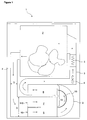
- the laundry dryer (1) comprises a body, a drum (2) wherein the laundry is placed, a drying duct (3) wherein the process air is circulated, a fan (4) providing the circulation of the process air in the drying duct (3), a heater (5) that heats the process air, a condenser (6) that dehumidifies the moisture in the process air and a thermoelectric heat pump (9) disposed in the drying duct (3), having a cold side (7) that condenses the process air passing there over by cooling it and a hot side (8) that heats the process air passing there over.
- the laundry dryer (1) furthermore comprises a first inlet opening (10) providing the process air moving through the drying duct (3) to enter the condenser (6) and a second inlet opening (110) providing the said process air to enter the cold side (7).
- thermoelectric heat pump (9) is positioned horizontally inside the body of the laundry dryer (1), the cold side (7) is situated below, and the hot side (8) above, and the condenser (6) is situated under the cold side (7), at the lowermost place inside the body of the laundry dryer (1).
- the said elements are arranged one above the other from the drum (2) towards the base in the order as the hot side (8) - the cold side (7) - the condenser (6).
- the laundry dryer (1) of the present invention comprises
- the process air leaving the drum (2) and moving through the drying duct (3) enters both the condenser (6) and the cold side (7) that are disposed on the flow path and that are adjacent and one above the other through the openings (10, 110)
- the condenser (6) and the cold side (7) are connected in parallel to each other in the process air flow direction in the drying duct (3) and work as a single condensing unit.
- the inlet openings (10, 110) positioned one above the other at the same level serve as a separator (12), the process air traverses the condenser (6) and the cold side (7) from end to end by entering both and without being separated by any additional separator (12), and flow in the condenser (6) and the cold side (7) does not mix with each other.
- the hot side (8) is connected to both the condenser (6) and the cold side (7).
- the process air leaving the condenser (6) and the cold side (7) joins and is guided to the hot side (8) by the drying duct (3).
- the process air being separated by the inlet openings (10, 110) and then simultaneously flowing through the condenser (6) and the cold side (7), the total flow path of the process air in the laundry dryer (1) is shortened and pressure losses are decreased.
- the drying duct (3) is connected to the condenser (6) and the cold side (7) by increasing the air flow cross sectional area (D) at least near the inlet openings (10, 110) so as to surround the inlet openings (10, 110). Since the cross sectional area (D) of the drying duct (3) is increased, the flow rate of the process air at this region decreases and the condensing efficiency of the condenser (6) and the cold side (7) increases depending on the decreasing air flow rate.
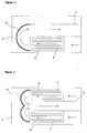
- the laundry dryer (1) comprises a vertical guide (11) that is disposed at one end of the hot side (8) and that rotates 180 degrees the flow direction of the process air coming from the condenser (6) and the cold side (7) and traversing the hot side (8) from end to end and guides it again into the hot side (8) such that it flows in the opposite direction, and furthermore a separator (12) that prevents the air flows in opposite directions from mixing with each other in the hot side (8) by separating the hot side (8) into two parts ( Figure 2 ).
- the fins (F) of the hot side (8) extend upwards in the vertical direction and the separator (12) separates the fins (F) of the hot side (8) into one lower and one upper part by extending horizontally in the middle of the fins (F) ( Figure 2 ).
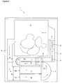
- the laundry dryer (1) comprises a horizontal guide (14) that is disposed at one end of the hot side (8) and that provides the process air coming from the condenser (6) and the cold side (7) and traversing the hot side (8) from end to end to be horizontally returned by the side of the hot side (8) below the drum (2) ( Figure 3 ).
- the laundry dryer (1) comprises two hot sides (8) disposed side by side at the lower side of the drum (2) and the horizontal guide (14) that is disposed at one end of the hot sides (8) and that joins the process air coming from the condenser (6) and the cold side (7) and traversing the hot sides (8) from end to end and provides it to be returned from between the two hot sides (8) ( Figure 4 ).
- the process air moves to the right of the drum (2) after leaving the condenser (6) and the cold side (7) since it flows in the condenser (6) and the cold side (7) at the same time. Since the hot side (8) is connected in series to the condenser (6) and the cold side (7) and due to the one-above-the-other arrangement in the body, the process air passing through the hot side (8) once again comes to the left side of the drum (2).
- the process air stays at a distance from the outlet of the hot side (8) and it is required to transport the process air leaving the hot side (8) from the left side thereof to the right side of the drum (2) again. And this means forming a new flow path that carries the process air from left to right in the limited volume below the drum (2).
- the condenser (6), the cold side (7) and the hot side (8), all disposed below the drum (2) occupy much space in the vertical direction in the body of the laundry dryer (1) together with the drying duct (3).
- the laundry dryer (1) comprises an inner guide (13) that is disposed at the portion of the drying duct (3) connecting the condenser (6) and the cold side (7) with the hot side (8) and that guides the process air flows leaving the condenser (6) and the cold side (7) to the hot side (8) by separating them ( Figure 1 ).
- an inner guide (13) that is disposed at the portion of the drying duct (3) connecting the condenser (6) and the cold side (7) with the hot side (8) and that guides the process air flows leaving the condenser (6) and the cold side (7) to the hot side (8) by separating them ( Figure 1 ).
- the air flow passing there over should be at high speeds. Since the cold side (7) performs condensing, the air flow passing there over should be at lower speeds for it operating efficiently. If the air passes through the hot side (8) and the cold side (7) of the thermoelectric heat pump (9) at the same speed, if the air flow rate is high, the cold side (7) operates inefficiently while the hot side (8) operates efficiently, and if the air flow rate is low, this time, the cold side (7) operates efficiently, while the hot side (8) operates inefficiently.
- the process air is provided to pass through the cold side (7) and the condenser (6) at lower speeds by increasing the cross sectional area (D) of the drying duct (3) such that the drying duct (3) can be connected to both the cold side (7) and the condenser (6), thus the efficiency of both the cold side (7) and the condenser (6) is increased.
- the process air is provided to pass through the hot side (8) at high speeds by decreasing the cross sectional area (D) of the drying duct (3) before the inlet of the hot side (8), thus the efficiency of the hot side (8) is increased.
- the condenser (6) and the cold side (7) operates as a single unit, they can be curvedly placed in the same direction, the condensing water of both can be collected in a common collecting container by using a single discharge line, thus separate condensing water collecting containers are not needed to be used for the condenser (6) and the cold side (7).
Landscapes
- Engineering & Computer Science (AREA)
- Textile Engineering (AREA)
- Detail Structures Of Washing Machines And Dryers (AREA)
- Drying Of Solid Materials (AREA)
Claims (7)
- Un sèche-linge (1) comprenant un tambour (2) dans lequel le linge est placé, une conduite de séchage (3) dans laquelle l'air de processus est circulé, un ventilateur (4) permettant la circulation de l'air de processus dans la conduite de séchage (3), un dispositif de chauffage (5) qui chauffe l'air de processus, un condenseur (6) qui déshumidifie l'air de processus et une pompe à chaleur thermoélectrique (9) qui est disposée dans la conduite de séchage (3) et qui présente un côté froid (7) qui condense l'air de processus passant sur celui-ci en le refroidissant et un côté chaud (8) qui chauffe l'air de processus passant sur celui-ci, une première ouverture d'entrée (10) qui permet à l'entrée de l'air de processus écoulant dans la conduite de séchage (3) d'entrer dans le condenseur (6) et une deuxième ouverture d'entrée (110) qui permet audit air de processus d'entrer dans le côté froid (7),
caractérisé en ce que- le condenseur (6) et le côté froid (7) sont placés côte à côte de telle sorte que leurs ouvertures d'entrée (10, 110) se restent dans la même direction et en ce que- la conduite de séchage (3) est reliée au condenseur (6) et au côté froid (7), permettant à l'air de processus de passer à travers les ouvertures d'entrée (10, 110) et d'écouler en parallèle à travers le condenseur (6) et le côté froid (7) et guidant l'air de processus sortant du condenseur (6) et du côté froid (7) vers le côté chaud (8) en les joignant. - Un sèche-linge (1) selon la Revendication 1, caractérisé en ce que la surface de section transversale (D) du flux d'air de la conduite de séchage (3) qui est reliée au condenseur (6) et au côté froid (7) est augmenté de manière à entourer les ouvertures d'entrée (10, 110).
- Un sèche-linge (1) selon la Revendication 1 ou 2, caractérisé par un guide vertical (11) qui est disposé à une extrémité du côté chaud (8) et qui tourne de 180 degrés la direction d'écoulement de l'air de processus venant du condenseur (6) et du côté froid (7) et traversant le côté chaud (8) de bout en bout et qui le guide de nouveau dans le côté chaud (8), et un séparateur (12) qui empêche les écoulements d'air dans des directions opposées de mélanger les uns avec les autres dans le côté chaud (8) en séparant le côté chaud (8) en deux parties.
- Un sèche-linge (1) selon la Revendication 3, caractérisé par le côté chaud (8) dont les ailettes (F) s'étendent vers le haut dans la direction verticale, et le séparateur (12) qui sépare le côté chaud (8) en une partie inférieure et une partie supérieure en s'étendant horizontalement au milieu des ailettes (F).
- Un sèche-linge (1) selon la Revendication 1 ou 2, caractérisé par un guide horizontal (14) qui est disposé à une extrémité du côté chaud (8) et qui permet à l'air de processus venant du condenseur (6) et du côté froid (7) et traversant le côté chaud (8) d'être retourné horizontalement par le côté du côté chaud (8).
- Un sèche-linge (1) selon la Revendication 1, 2 ou 5, caractérisé par deux côtés chauds (8) qui sont disposés côte à côte, et le guide horizontal (14) qui est disposé à une extrémité des côtés chauds (8) et qui joint l'air de processus venant du condenseur (6) et du côté froid (7) et traversant le côté chaud (8) et lui permet d'être retourné entre les deux côtés chauds (8).
- Un sèche-linge (1) selon l'une quelconque des revendications précédentes, caractérisé par un guide intérieur (13) qui est disposé à la partie de la conduite de séchage (3) reliant le condenseur (6) et le côté froid (7) avec le côté chaud (8) et qui guide les écoulements de l'air de processus sortant du condenseur (6) et du côté froid (7) vers le côté chaud (8) en les séparant.
Applications Claiming Priority (2)
| Application Number | Priority Date | Filing Date | Title |
|---|---|---|---|
| TR201009345 | 2010-11-10 | ||
| PCT/EP2011/069481 WO2012062677A1 (fr) | 2010-11-10 | 2011-11-04 | Sèche-linge à pompe à chaleur thermoélectrique |
Publications (2)
| Publication Number | Publication Date |
|---|---|
| EP2638202A1 EP2638202A1 (fr) | 2013-09-18 |
| EP2638202B1 true EP2638202B1 (fr) | 2016-01-27 |
Family
ID=44910212
Family Applications (1)
| Application Number | Title | Priority Date | Filing Date |
|---|---|---|---|
| EP11779401.6A Not-in-force EP2638202B1 (fr) | 2010-11-10 | 2011-11-04 | Sèche-linge à pompe à chaleur thermoélectrique |
Country Status (3)
| Country | Link |
|---|---|
| EP (1) | EP2638202B1 (fr) |
| CN (1) | CN103201424B (fr) |
| WO (1) | WO2012062677A1 (fr) |
Families Citing this family (7)
| Publication number | Priority date | Publication date | Assignee | Title |
|---|---|---|---|---|
| CH705546A3 (de) * | 2013-01-23 | 2014-03-31 | V Zug Ag | Wäschetrockner mit Zusatzheizung und Zusatzwärmetauscher. |
| CN103388972A (zh) * | 2013-07-17 | 2013-11-13 | 孔令斌 | 一种斯特林热泵烘干机 |
| CN104593992A (zh) * | 2013-10-30 | 2015-05-06 | 海尔集团公司 | 一种波轮式热泵洗干一体机及烘干方法 |
| CN104846609A (zh) * | 2014-02-13 | 2015-08-19 | 海尔集团技术研发中心 | 一种洗衣装置和用于洗衣装置的衣物烘干方法 |
| CN105937160A (zh) * | 2016-05-31 | 2016-09-14 | 无锡小天鹅股份有限公司 | 干衣机或洗干一体机 |
| CN115110282B (zh) * | 2021-03-18 | 2025-08-26 | 天津海尔洗涤电器有限公司 | 用于烘干设备的冷凝器及烘干设备 |
| CN113047016A (zh) * | 2021-03-22 | 2021-06-29 | Tcl家用电器(合肥)有限公司 | 一种热泵干衣机、控制系统及控制方法 |
Family Cites Families (6)
| Publication number | Priority date | Publication date | Assignee | Title |
|---|---|---|---|---|
| JPH0857194A (ja) * | 1994-08-26 | 1996-03-05 | Matsushita Electric Ind Co Ltd | 除湿型電気衣類乾燥機 |
| DE20101641U1 (de) | 2001-01-29 | 2002-06-06 | AKG-Thermotechnik GmbH & Co. KG, 34369 Hofgeismar | Kondensations-Wäschetrockner und dafür geeigneter Kondensations-Wärmeaustauscher |
| US7526879B2 (en) * | 2005-11-04 | 2009-05-05 | Lg Electronics Inc. | Drum washing machine and clothes dryer using peltier thermoelectric module |
| DE102006005810A1 (de) | 2006-02-08 | 2007-08-16 | BSH Bosch und Siemens Hausgeräte GmbH | Dichtungsvorrichtung für eine Wärmetauscheranordnung |
| DE102006016294A1 (de) | 2006-04-06 | 2007-10-11 | BSH Bosch und Siemens Hausgeräte GmbH | Hausgerät zur Pflege von Wäschestücken |
| DE102006026251A1 (de) | 2006-06-06 | 2007-12-13 | BSH Bosch und Siemens Hausgeräte GmbH | Vorrichtung und Verfahren zum Trocknen von Waschgut |
-
2011
- 2011-11-04 EP EP11779401.6A patent/EP2638202B1/fr not_active Not-in-force
- 2011-11-04 WO PCT/EP2011/069481 patent/WO2012062677A1/fr not_active Ceased
- 2011-11-04 CN CN201180054362.3A patent/CN103201424B/zh not_active Expired - Fee Related
Also Published As
| Publication number | Publication date |
|---|---|
| CN103201424B (zh) | 2015-12-02 |
| CN103201424A (zh) | 2013-07-10 |
| EP2638202A1 (fr) | 2013-09-18 |
| WO2012062677A1 (fr) | 2012-05-18 |
Similar Documents
| Publication | Publication Date | Title |
|---|---|---|
| EP2576888B1 (fr) | Sèche-linge à pompe à chaleur thermoélectrique | |
| WO2012062677A1 (fr) | Sèche-linge à pompe à chaleur thermoélectrique | |
| EP2702199B1 (fr) | Seche linge a pompe thermique | |
| JP6069797B2 (ja) | 衣類乾燥凝縮用熱交換器、衣類乾燥手段、衣類乾燥機、および衣類乾燥方法 | |
| US9249538B2 (en) | Laundry treatment apparatus with heat pump | |
| CN101356311B (zh) | 具有另外冷凝器的家用干衣机 | |
| EP2925924B1 (fr) | Machine à laver à chargement frontal ayant un système de séchage incorporé | |
| CN104711833B (zh) | 干衣机 | |
| EP2519686B1 (fr) | Sèche-linge à pompe à chaleur | |
| EP2573253B1 (fr) | Sèche-linge à pompe à chaleur | |
| CN110331566A (zh) | 烘干系统及其使用方法 | |
| EP3088597A1 (fr) | Sèche-linge | |
| EP2452009B1 (fr) | Sèche-linge | |
| CN103015140A (zh) | 干衣机 | |
| EP3241943B1 (fr) | Appareil ménager comprenant un échangeur de chaleur à eau/air de processus | |
| WO2014146953A1 (fr) | Appareil de traitement de linge ayant une pompe à chaleur | |
| CN206346058U (zh) | 用于衣物处理设备的冷凝器和具有其的衣物处理设备 | |
| CN107447471A (zh) | 热泵系统的基座和用于干衣机或洗干一体机的热泵系统 | |
| US9945063B2 (en) | Washing machine with heat pump system | |
| EP2549007B1 (fr) | Appareil de traitement de linge à pompe thermique | |
| CN106012457A (zh) | 洗涤物处理装置 | |
| WO2013000955A2 (fr) | Sèche-linge équipé d'une pompe à chaleur thermo-électrique | |
| CN107022866A (zh) | 洗干一体机及其控制方法 | |
| EP2452008B1 (fr) | Sèche-linge | |
| CN214613200U (zh) | 一种用于衣物处理装置的冷凝机构及衣物处理装置 |
Legal Events
| Date | Code | Title | Description |
|---|---|---|---|
| PUAI | Public reference made under article 153(3) epc to a published international application that has entered the european phase |
Free format text: ORIGINAL CODE: 0009012 |
|
| 17P | Request for examination filed |
Effective date: 20130416 |
|
| AK | Designated contracting states |
Kind code of ref document: A1 Designated state(s): AL AT BE BG CH CY CZ DE DK EE ES FI FR GB GR HR HU IE IS IT LI LT LU LV MC MK MT NL NO PL PT RO RS SE SI SK SM TR |
|
| DAX | Request for extension of the european patent (deleted) | ||
| GRAP | Despatch of communication of intention to grant a patent |
Free format text: ORIGINAL CODE: EPIDOSNIGR1 |
|
| INTG | Intention to grant announced |
Effective date: 20151001 |
|
| GRAS | Grant fee paid |
Free format text: ORIGINAL CODE: EPIDOSNIGR3 |
|
| GRAA | (expected) grant |
Free format text: ORIGINAL CODE: 0009210 |
|
| AK | Designated contracting states |
Kind code of ref document: B1 Designated state(s): AL AT BE BG CH CY CZ DE DK EE ES FI FR GB GR HR HU IE IS IT LI LT LU LV MC MK MT NL NO PL PT RO RS SE SI SK SM TR |
|
| REG | Reference to a national code |
Ref country code: GB Ref legal event code: FG4D |
|
| REG | Reference to a national code |
Ref country code: CH Ref legal event code: EP |
|
| REG | Reference to a national code |
Ref country code: AT Ref legal event code: REF Ref document number: 772781 Country of ref document: AT Kind code of ref document: T Effective date: 20160215 |
|
| REG | Reference to a national code |
Ref country code: IE Ref legal event code: FG4D |
|
| REG | Reference to a national code |
Ref country code: DE Ref legal event code: R096 Ref document number: 602011023041 Country of ref document: DE |
|
| REG | Reference to a national code |
Ref country code: LT Ref legal event code: MG4D |
|
| REG | Reference to a national code |
Ref country code: NL Ref legal event code: MP Effective date: 20160127 |
|
| REG | Reference to a national code |
Ref country code: AT Ref legal event code: MK05 Ref document number: 772781 Country of ref document: AT Kind code of ref document: T Effective date: 20160127 |
|
| PG25 | Lapsed in a contracting state [announced via postgrant information from national office to epo] |
Ref country code: NL Free format text: LAPSE BECAUSE OF FAILURE TO SUBMIT A TRANSLATION OF THE DESCRIPTION OR TO PAY THE FEE WITHIN THE PRESCRIBED TIME-LIMIT Effective date: 20160127 |
|
| PG25 | Lapsed in a contracting state [announced via postgrant information from national office to epo] |
Ref country code: HR Free format text: LAPSE BECAUSE OF FAILURE TO SUBMIT A TRANSLATION OF THE DESCRIPTION OR TO PAY THE FEE WITHIN THE PRESCRIBED TIME-LIMIT Effective date: 20160127 Ref country code: GR Free format text: LAPSE BECAUSE OF FAILURE TO SUBMIT A TRANSLATION OF THE DESCRIPTION OR TO PAY THE FEE WITHIN THE PRESCRIBED TIME-LIMIT Effective date: 20160428 Ref country code: FI Free format text: LAPSE BECAUSE OF FAILURE TO SUBMIT A TRANSLATION OF THE DESCRIPTION OR TO PAY THE FEE WITHIN THE PRESCRIBED TIME-LIMIT Effective date: 20160127 Ref country code: IT Free format text: LAPSE BECAUSE OF FAILURE TO SUBMIT A TRANSLATION OF THE DESCRIPTION OR TO PAY THE FEE WITHIN THE PRESCRIBED TIME-LIMIT Effective date: 20160127 Ref country code: NO Free format text: LAPSE BECAUSE OF FAILURE TO SUBMIT A TRANSLATION OF THE DESCRIPTION OR TO PAY THE FEE WITHIN THE PRESCRIBED TIME-LIMIT Effective date: 20160427 Ref country code: ES Free format text: LAPSE BECAUSE OF FAILURE TO SUBMIT A TRANSLATION OF THE DESCRIPTION OR TO PAY THE FEE WITHIN THE PRESCRIBED TIME-LIMIT Effective date: 20160127 |
|
| PG25 | Lapsed in a contracting state [announced via postgrant information from national office to epo] |
Ref country code: LT Free format text: LAPSE BECAUSE OF FAILURE TO SUBMIT A TRANSLATION OF THE DESCRIPTION OR TO PAY THE FEE WITHIN THE PRESCRIBED TIME-LIMIT Effective date: 20160127 Ref country code: LV Free format text: LAPSE BECAUSE OF FAILURE TO SUBMIT A TRANSLATION OF THE DESCRIPTION OR TO PAY THE FEE WITHIN THE PRESCRIBED TIME-LIMIT Effective date: 20160127 Ref country code: IS Free format text: LAPSE BECAUSE OF FAILURE TO SUBMIT A TRANSLATION OF THE DESCRIPTION OR TO PAY THE FEE WITHIN THE PRESCRIBED TIME-LIMIT Effective date: 20160527 Ref country code: PL Free format text: LAPSE BECAUSE OF FAILURE TO SUBMIT A TRANSLATION OF THE DESCRIPTION OR TO PAY THE FEE WITHIN THE PRESCRIBED TIME-LIMIT Effective date: 20160127 Ref country code: AT Free format text: LAPSE BECAUSE OF FAILURE TO SUBMIT A TRANSLATION OF THE DESCRIPTION OR TO PAY THE FEE WITHIN THE PRESCRIBED TIME-LIMIT Effective date: 20160127 Ref country code: RS Free format text: LAPSE BECAUSE OF FAILURE TO SUBMIT A TRANSLATION OF THE DESCRIPTION OR TO PAY THE FEE WITHIN THE PRESCRIBED TIME-LIMIT Effective date: 20160127 Ref country code: PT Free format text: LAPSE BECAUSE OF FAILURE TO SUBMIT A TRANSLATION OF THE DESCRIPTION OR TO PAY THE FEE WITHIN THE PRESCRIBED TIME-LIMIT Effective date: 20160527 Ref country code: SE Free format text: LAPSE BECAUSE OF FAILURE TO SUBMIT A TRANSLATION OF THE DESCRIPTION OR TO PAY THE FEE WITHIN THE PRESCRIBED TIME-LIMIT Effective date: 20160127 |
|
| PGFP | Annual fee paid to national office [announced via postgrant information from national office to epo] |
Ref country code: TR Payment date: 20160428 Year of fee payment: 6 |
|
| REG | Reference to a national code |
Ref country code: DE Ref legal event code: R097 Ref document number: 602011023041 Country of ref document: DE |
|
| PG25 | Lapsed in a contracting state [announced via postgrant information from national office to epo] |
Ref country code: EE Free format text: LAPSE BECAUSE OF FAILURE TO SUBMIT A TRANSLATION OF THE DESCRIPTION OR TO PAY THE FEE WITHIN THE PRESCRIBED TIME-LIMIT Effective date: 20160127 Ref country code: DK Free format text: LAPSE BECAUSE OF FAILURE TO SUBMIT A TRANSLATION OF THE DESCRIPTION OR TO PAY THE FEE WITHIN THE PRESCRIBED TIME-LIMIT Effective date: 20160127 |
|
| REG | Reference to a national code |
Ref country code: FR Ref legal event code: PLFP Year of fee payment: 6 |
|
| PG25 | Lapsed in a contracting state [announced via postgrant information from national office to epo] |
Ref country code: CZ Free format text: LAPSE BECAUSE OF FAILURE TO SUBMIT A TRANSLATION OF THE DESCRIPTION OR TO PAY THE FEE WITHIN THE PRESCRIBED TIME-LIMIT Effective date: 20160127 Ref country code: SK Free format text: LAPSE BECAUSE OF FAILURE TO SUBMIT A TRANSLATION OF THE DESCRIPTION OR TO PAY THE FEE WITHIN THE PRESCRIBED TIME-LIMIT Effective date: 20160127 Ref country code: RO Free format text: LAPSE BECAUSE OF FAILURE TO SUBMIT A TRANSLATION OF THE DESCRIPTION OR TO PAY THE FEE WITHIN THE PRESCRIBED TIME-LIMIT Effective date: 20160127 Ref country code: SM Free format text: LAPSE BECAUSE OF FAILURE TO SUBMIT A TRANSLATION OF THE DESCRIPTION OR TO PAY THE FEE WITHIN THE PRESCRIBED TIME-LIMIT Effective date: 20160127 |
|
| PLBE | No opposition filed within time limit |
Free format text: ORIGINAL CODE: 0009261 |
|
| STAA | Information on the status of an ep patent application or granted ep patent |
Free format text: STATUS: NO OPPOSITION FILED WITHIN TIME LIMIT |
|
| PG25 | Lapsed in a contracting state [announced via postgrant information from national office to epo] |
Ref country code: BE Free format text: LAPSE BECAUSE OF FAILURE TO SUBMIT A TRANSLATION OF THE DESCRIPTION OR TO PAY THE FEE WITHIN THE PRESCRIBED TIME-LIMIT Effective date: 20160127 |
|
| 26N | No opposition filed |
Effective date: 20161028 |
|
| PGFP | Annual fee paid to national office [announced via postgrant information from national office to epo] |
Ref country code: FR Payment date: 20161118 Year of fee payment: 6 Ref country code: DE Payment date: 20161121 Year of fee payment: 6 Ref country code: GB Payment date: 20161122 Year of fee payment: 6 |
|
| PG25 | Lapsed in a contracting state [announced via postgrant information from national office to epo] |
Ref country code: BG Free format text: LAPSE BECAUSE OF FAILURE TO SUBMIT A TRANSLATION OF THE DESCRIPTION OR TO PAY THE FEE WITHIN THE PRESCRIBED TIME-LIMIT Effective date: 20160427 Ref country code: SI Free format text: LAPSE BECAUSE OF FAILURE TO SUBMIT A TRANSLATION OF THE DESCRIPTION OR TO PAY THE FEE WITHIN THE PRESCRIBED TIME-LIMIT Effective date: 20160127 |
|
| REG | Reference to a national code |
Ref country code: CH Ref legal event code: PL |
|
| PG25 | Lapsed in a contracting state [announced via postgrant information from national office to epo] |
Ref country code: LI Free format text: LAPSE BECAUSE OF NON-PAYMENT OF DUE FEES Effective date: 20161130 Ref country code: CH Free format text: LAPSE BECAUSE OF NON-PAYMENT OF DUE FEES Effective date: 20161130 |
|
| REG | Reference to a national code |
Ref country code: IE Ref legal event code: MM4A |
|
| PG25 | Lapsed in a contracting state [announced via postgrant information from national office to epo] |
Ref country code: LU Free format text: LAPSE BECAUSE OF NON-PAYMENT OF DUE FEES Effective date: 20161130 |
|
| PG25 | Lapsed in a contracting state [announced via postgrant information from national office to epo] |
Ref country code: IE Free format text: LAPSE BECAUSE OF NON-PAYMENT OF DUE FEES Effective date: 20161104 |
|
| PG25 | Lapsed in a contracting state [announced via postgrant information from national office to epo] |
Ref country code: HU Free format text: LAPSE BECAUSE OF FAILURE TO SUBMIT A TRANSLATION OF THE DESCRIPTION OR TO PAY THE FEE WITHIN THE PRESCRIBED TIME-LIMIT; INVALID AB INITIO Effective date: 20111104 Ref country code: CY Free format text: LAPSE BECAUSE OF FAILURE TO SUBMIT A TRANSLATION OF THE DESCRIPTION OR TO PAY THE FEE WITHIN THE PRESCRIBED TIME-LIMIT Effective date: 20160127 |
|
| REG | Reference to a national code |
Ref country code: DE Ref legal event code: R119 Ref document number: 602011023041 Country of ref document: DE |
|
| PG25 | Lapsed in a contracting state [announced via postgrant information from national office to epo] |
Ref country code: MK Free format text: LAPSE BECAUSE OF FAILURE TO SUBMIT A TRANSLATION OF THE DESCRIPTION OR TO PAY THE FEE WITHIN THE PRESCRIBED TIME-LIMIT Effective date: 20160127 Ref country code: MC Free format text: LAPSE BECAUSE OF FAILURE TO SUBMIT A TRANSLATION OF THE DESCRIPTION OR TO PAY THE FEE WITHIN THE PRESCRIBED TIME-LIMIT Effective date: 20160127 |
|
| GBPC | Gb: european patent ceased through non-payment of renewal fee |
Effective date: 20171104 |
|
| REG | Reference to a national code |
Ref country code: FR Ref legal event code: ST Effective date: 20180731 |
|
| PG25 | Lapsed in a contracting state [announced via postgrant information from national office to epo] |
Ref country code: MT Free format text: LAPSE BECAUSE OF NON-PAYMENT OF DUE FEES Effective date: 20161104 |
|
| PG25 | Lapsed in a contracting state [announced via postgrant information from national office to epo] |
Ref country code: DE Free format text: LAPSE BECAUSE OF NON-PAYMENT OF DUE FEES Effective date: 20180602 Ref country code: FR Free format text: LAPSE BECAUSE OF NON-PAYMENT OF DUE FEES Effective date: 20171130 Ref country code: AL Free format text: LAPSE BECAUSE OF FAILURE TO SUBMIT A TRANSLATION OF THE DESCRIPTION OR TO PAY THE FEE WITHIN THE PRESCRIBED TIME-LIMIT Effective date: 20160127 |
|
| PG25 | Lapsed in a contracting state [announced via postgrant information from national office to epo] |
Ref country code: GB Free format text: LAPSE BECAUSE OF NON-PAYMENT OF DUE FEES Effective date: 20171104 |
|
| PG25 | Lapsed in a contracting state [announced via postgrant information from national office to epo] |
Ref country code: TR Free format text: LAPSE BECAUSE OF NON-PAYMENT OF DUE FEES Effective date: 20171104 |