EP2638256B1 - Dispositif de réglage d'arbre à cames pour moteur à combustion interne - Google Patents
Dispositif de réglage d'arbre à cames pour moteur à combustion interne Download PDFInfo
- Publication number
- EP2638256B1 EP2638256B1 EP11748378.4A EP11748378A EP2638256B1 EP 2638256 B1 EP2638256 B1 EP 2638256B1 EP 11748378 A EP11748378 A EP 11748378A EP 2638256 B1 EP2638256 B1 EP 2638256B1
- Authority
- EP
- European Patent Office
- Prior art keywords
- adapter
- camshaft
- output gear
- gear
- camshaft adjuster
- Prior art date
- Legal status (The legal status is an assumption and is not a legal conclusion. Google has not performed a legal analysis and makes no representation as to the accuracy of the status listed.)
- Not-in-force
Links
Images

Classifications
-
- F—MECHANICAL ENGINEERING; LIGHTING; HEATING; WEAPONS; BLASTING
- F01—MACHINES OR ENGINES IN GENERAL; ENGINE PLANTS IN GENERAL; STEAM ENGINES
- F01L—CYCLICALLY OPERATING VALVES FOR MACHINES OR ENGINES
- F01L1/00—Valve-gear or valve arrangements, e.g. lift-valve gear
- F01L1/34—Valve-gear or valve arrangements, e.g. lift-valve gear characterised by the provision of means for changing the timing of the valves without changing the duration of opening and without affecting the magnitude of the valve lift
- F01L1/344—Valve-gear or valve arrangements, e.g. lift-valve gear characterised by the provision of means for changing the timing of the valves without changing the duration of opening and without affecting the magnitude of the valve lift changing the angular relationship between crankshaft and camshaft, e.g. using helicoidal gear
-
- F—MECHANICAL ENGINEERING; LIGHTING; HEATING; WEAPONS; BLASTING
- F01—MACHINES OR ENGINES IN GENERAL; ENGINE PLANTS IN GENERAL; STEAM ENGINES
- F01L—CYCLICALLY OPERATING VALVES FOR MACHINES OR ENGINES
- F01L1/00—Valve-gear or valve arrangements, e.g. lift-valve gear
- F01L1/34—Valve-gear or valve arrangements, e.g. lift-valve gear characterised by the provision of means for changing the timing of the valves without changing the duration of opening and without affecting the magnitude of the valve lift
- F01L1/344—Valve-gear or valve arrangements, e.g. lift-valve gear characterised by the provision of means for changing the timing of the valves without changing the duration of opening and without affecting the magnitude of the valve lift changing the angular relationship between crankshaft and camshaft, e.g. using helicoidal gear
- F01L1/352—Valve-gear or valve arrangements, e.g. lift-valve gear characterised by the provision of means for changing the timing of the valves without changing the duration of opening and without affecting the magnitude of the valve lift changing the angular relationship between crankshaft and camshaft, e.g. using helicoidal gear using bevel or epicyclic gear
-
- F—MECHANICAL ENGINEERING; LIGHTING; HEATING; WEAPONS; BLASTING
- F01—MACHINES OR ENGINES IN GENERAL; ENGINE PLANTS IN GENERAL; STEAM ENGINES
- F01L—CYCLICALLY OPERATING VALVES FOR MACHINES OR ENGINES
- F01L1/00—Valve-gear or valve arrangements, e.g. lift-valve gear
- F01L1/34—Valve-gear or valve arrangements, e.g. lift-valve gear characterised by the provision of means for changing the timing of the valves without changing the duration of opening and without affecting the magnitude of the valve lift
-
- F—MECHANICAL ENGINEERING; LIGHTING; HEATING; WEAPONS; BLASTING
- F02—COMBUSTION ENGINES; HOT-GAS OR COMBUSTION-PRODUCT ENGINE PLANTS
- F02F—CYLINDERS, PISTONS OR CASINGS, FOR COMBUSTION ENGINES; ARRANGEMENTS OF SEALINGS IN COMBUSTION ENGINES
- F02F1/00—Cylinders; Cylinder heads
- F02F1/24—Cylinder heads
-
- F—MECHANICAL ENGINEERING; LIGHTING; HEATING; WEAPONS; BLASTING
- F16—ENGINEERING ELEMENTS AND UNITS; GENERAL MEASURES FOR PRODUCING AND MAINTAINING EFFECTIVE FUNCTIONING OF MACHINES OR INSTALLATIONS; THERMAL INSULATION IN GENERAL
- F16H—GEARING
- F16H1/00—Toothed gearings for conveying rotary motion
- F16H1/02—Toothed gearings for conveying rotary motion without gears having orbital motion
- F16H1/04—Toothed gearings for conveying rotary motion without gears having orbital motion involving only two intermeshing members
- F16H1/06—Toothed gearings for conveying rotary motion without gears having orbital motion involving only two intermeshing members with parallel axes
- F16H1/10—Toothed gearings for conveying rotary motion without gears having orbital motion involving only two intermeshing members with parallel axes one of the members being internally toothed
-
- F—MECHANICAL ENGINEERING; LIGHTING; HEATING; WEAPONS; BLASTING
- F16—ENGINEERING ELEMENTS AND UNITS; GENERAL MEASURES FOR PRODUCING AND MAINTAINING EFFECTIVE FUNCTIONING OF MACHINES OR INSTALLATIONS; THERMAL INSULATION IN GENERAL
- F16H—GEARING
- F16H1/00—Toothed gearings for conveying rotary motion
- F16H1/28—Toothed gearings for conveying rotary motion with gears having orbital motion
- F16H1/36—Toothed gearings for conveying rotary motion with gears having orbital motion with two central gears coupled by intermeshing orbital gears
-
- F—MECHANICAL ENGINEERING; LIGHTING; HEATING; WEAPONS; BLASTING
- F16—ENGINEERING ELEMENTS AND UNITS; GENERAL MEASURES FOR PRODUCING AND MAINTAINING EFFECTIVE FUNCTIONING OF MACHINES OR INSTALLATIONS; THERMAL INSULATION IN GENERAL
- F16H—GEARING
- F16H57/00—General details of gearing
- F16H57/02—Gearboxes; Mounting gearing therein
-
- F—MECHANICAL ENGINEERING; LIGHTING; HEATING; WEAPONS; BLASTING
- F16—ENGINEERING ELEMENTS AND UNITS; GENERAL MEASURES FOR PRODUCING AND MAINTAINING EFFECTIVE FUNCTIONING OF MACHINES OR INSTALLATIONS; THERMAL INSULATION IN GENERAL
- F16H—GEARING
- F16H57/00—General details of gearing
- F16H57/04—Features relating to lubrication or cooling or heating
Definitions
- the invention relates to a camshaft adjuster for an internal combustion engine, comprising a rotatably connectable to a crankshaft drive wheel, a relatively rotatable about a rotation axis arranged internally toothed driven wheel, and an adapter which is arranged on the inner circumference of the driven gear and the output shaft rotatably with a Camshaft is connectable.
- a camshaft adjuster is used for the targeted adjustment of the phase position between a camshaft and a crankshaft in an internal combustion engine and thus enables the optimized setting of the valve timing over the engine load and the engine speed. Thus, a significant reduction in fuel consumption and exhaust emissions and an increase in engine performance can be achieved.
- the camshaft adjusting device or the camshaft adjuster comprises a drive wheel and a driven wheel, which are arranged rotatable relative to one another.
- the drive wheel is for this purpose designed as a ring gear, in which the output gear is inserted.
- the output gear is formed on its inner circumference with an internal toothing and with an internal toothing adjacent annular receiving portion.
- the receiving portion serves to receive and position an adapter, via which the output gear is non-rotatably connected to a camshaft.
- the adapter is inserted into the output gear and welded there rotatably within the receiving portion.
- a camshaft adjuster for an internal combustion engine comprising one with a crankshaft rotatably connectable drive wheel, a relative to this about a rotation axis rotatably mounted, internally toothed output gear, and an adapter which is arranged on the inner circumference of the driven gear and via the output gear rotatably connected to a camshaft. It is provided that the adapter is attached via the internal toothing on the inner circumference of the driven gear.
- the invention takes into account that the trouble-free operation of a camshaft adjuster, the reliable torque transmission between the drive and output must be guaranteed.
- electromechanical camshaft adjusters usually a drive wheel is mounted on a driven wheel, which in turn is connected by means of an adapter with a camshaft.
- the adapter itself is in this case typically arranged within the output gear on the inner circumference, for which purpose a separately provided for this purpose exception section is provided on the inner circumference so far. This is not desirable in view of the associated with the production effort and the associated costs.
- the invention recognizes that this problem is surprisingly overcome by an attachment of the adapter via the internal toothing of the driven gear on its inner circumference.
- the hitherto necessary additional processing of the inner circumference of the output gear for fastening the adapter can be omitted.
- the adapter can be arranged on the driven wheel, without the introduction of a specially provided for receiving portion on the inner circumference of the driven wheel is necessary.
- the drive wheel is in particular designed as a ring gear and has an internal toothing, which may be formed partially or continuously on the inner circumference.
- the drive of the drive wheel is achieved via the rotationally fixed connection with a crankshaft.
- the drive wheel may be formed, for example, as a sprocket, wherein the rotationally fixed connection is achieved with the crankshaft via a chain.
- the output gear may also be designed as a pulley and be driven accordingly via a belt drive.
- the output gear On the inner circumference of the drive wheel, the output gear is usually arranged, wherein the drive wheel can be mounted on the output gear.
- the output gear is preferably also designed as a ring gear and has an internal toothing.
- the internal teeth are introduced in the manufacture of the output gear by means of a so-called Räumreaes in the inner circumference.
- a broach with a corresponding contour is pulled or pushed through an already introduced in the driven gear hole.
- the cross section of the broach here corresponds to the contour of the formed after the broaching process on the inner circumference of the driven gear internal teeth.
- the internal teeth can form an adjusting gear in the installed state together with the internal teeth of a driven gear, which can be driven for example via a spur gear of a shaft gear.
- only a part of the internal toothing of the output gear is then available, since the adapter is arranged in the mounted state on the inner circumference of the output gear.
- the adapter For positioning of the adapter, this is expediently formed with an outer diameter which is matched to the inner diameter of the driven gear.
- the adapter may be formed with a circular cross-section.
- the adapter can be inserted into the output gear and fixed there, so that it comes with its outer circumference on the inner circumference of the driven gear, or at the local internal teeth to the plant.
- the adapter with a counter toothing is formed, which engages in the internal toothing of the driven gear and the adapter so positioned.
- the adapter may be formed, for example, as a substantially flat end cover. It is preferably formed with a central bore through which a central screw for fastening the individual components of a camshaft adjuster can be passed to each other.
- the adapter can be screwed into the bore on the end face of the camshaft via the fastening of the central screw.
- the adapter can furthermore have recesses into which fastening elements formed on a front end of the camshaft can engage.
- the adapter is pressed onto the tip circle of the internal toothing of the driven gear.
- the tip diameter in gears typically refers to the outside diameter of the tooth circle, that is, the diameter given by the ends of the teeth.
- the pressing of the adapter on the top circle allows its simple arrangement on the inner circumference of the driven gear, since the receiving portion or the press-in portion is provided by the already existing internal toothing available.
- the insertion diameter of the press-in section for the adapter thus corresponds to the tip circle diameter of the internal toothing.
- a processing of the press-in can be omitted.
- the outer diameter of the adapter is in this case approximately the same size as that of the head circle diameter of the driven gear.
- connection produced by the pressing in principle can be either of solid or movable form.
- the connection points between the tooth ends and the outer circumference of the adapter can be transmitted.
- Furthermore remain when pressing the adapter on the tip circle of the internal teeth free spaces between the Teeth and the outer circumference of the adapter. These tooth clearances can be used for lubrication of the teeth.
- the internal toothing is formed axially continuously on the driven wheel.
- the continuous geometry of the internal toothing allows easy production or introduction of the internal toothing on the inner circumference of the driven wheel. Since a separate receiving section or press-fit paragraph for the adapter is not necessary, resulting in the inner circumference of an enlarged clearing length in the introduction of the internal teeth. This ensures a secure guidance of the broach used.
- the supporting portion of the internal toothing is increased by the continuous formation of the internal toothing, resulting in, for example, an extension of the life. Since the internal toothing is formed on the entire inner circumference of the output gear, is correspondingly the gear outlet in the mounted state axially end behind the adapter.
- the adapter is welded to the output gear, resulting in a secure connection of the two components results.
- the adapter and the driven gear are welded segmentally, in particular at the contact points between the tooth ends and the outer circumference of the adapter, so that the tooth clearances are available even after welding for lubricant.
- a laser welding which due to high welding speed, a narrow weld form and a low thermal distortion allows the required precision when connecting the components.
- the adapter is designed as a cover. Due to the design as a cover cover of the adapter in the installed state in addition to the torque transmission between a camshaft and a crankshaft, the adjusting gear on the camshaft axially facing side complete.
- the camshaft adjuster is thus protected, for example against external influences such as impurities or against leaks.
- the drive wheel is designed as a ring gear and mounted on the output gear.
- a sliding bearing is particularly suitable in which the two components which move relative to one another are in direct contact with one another. They slide against each other against the resistance caused by the sliding friction. This resistance can be reduced for example by the choice of low-friction material pairings or by lubrication.
- a slide bearing is particularly suitable, since in this case no additional space must be provided.
- a stop component for the camshaft is included, which is axially counterposed to the drive wheel.
- the stop component is designed as a stop ring with a stop surface for a camshaft.
- the abutment surface may for example be formed with a projection into which a recess on the end face of the camshaft can engage.
- a stop surface may be provided on the output gear itself.
- a rotational angle limiting between the drive wheel and the output shaft rotatably connected to the camshaft by means of the adapter is achieved by the stop surface.
- the stop component and the drive wheel are preferably at least partially, ie in particular in the area of the counter bearing, welded together.
- the stop component is rotatably connected to the drive wheel.
- other attachment options such as caulking or screwing conceivable.
- Fig. 1 shows a driven wheel 1 in a three-dimensional representation.
- the output gear 1 is annularly formed as a ring gear and has on its inner circumference 3 an internal toothing 5.
- an adapter can be attached to the driven wheel 1 in the mounted state. A detailed description can be found in the Fig. 3 to 6 ,
- the internal toothing 5 is formed both axially continuous on the inner circumference 3 of the output gear 1 and circumferentially on the entire inner circumference 3. This results in a continuous geometry, which makes it possible to introduce the internal toothing 5 in a simple manner by means of a broaching process in the inner circumference 3 of the driven wheel 1. Since a separate receiving portion for an adapter is not necessary, the production of the internal teeth 5 is facilitated. It results in the inner circumference 3 an enlarged reaming length, which allows a secure guidance of the broach used for evacuation.
- a broaching needle with a corresponding contour is drawn through a bore in the driven gear 1 to bring in the internal toothing 5.
- the broach here has a cross section which corresponds to the contour of the internal teeth 5 of the driven wheel 1, which are formed after broaching on the inner circumference 3.
- the internal teeth 5 formed after broaching consist of a number of teeth 7 adjacent to each other along the circumference.
- the ends 9 of the teeth 7 extending inwardly radially from the output gear 1 define the diameter of the tip circle 11 of the internal toothing 5.
- the teeth 7 extend in the output gear 1 from the inner circumference 3 of all equally far radially inward.
- Fig. 2 is the output gear according to Fig. 1 shown in a longitudinal section. Based on this representation, the axially continuous, so formed over the entire axial width 12 of the driven gear 1 internal teeth 5 is clearly visible. This embodiment is possible since no separate receiving section is necessary for attaching or fastening an adapter.
- the outer diameter in the area provided for fastening for an adapter thus corresponds to the diameter of the tip circle 11 of the internal toothing 5. A broach used for introducing the internal toothing 5 is thus securely guided over the entire axial width 12 of the driven wheel 1.
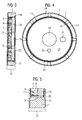
- Fig. 3 is the output gear 1 according to Fig. 1 to see with an adapter 13 in a longitudinal section.
- the adapter 13 is formed as a flat circular end cover and fixed on the inner toothing 5 on the inner circumference 3 of the driven wheel 1.
- the outer diameter 14 of the adapter 13 is approximately the same size as the diameter of the tip circle 11 of the driven wheel 1.
- the adapter 13 After evacuation of the driven gear 1, the adapter 13 is pressed onto the tip circle 11 of the internal toothing 5.
- the two components are rotatably connected to each other.
- the welding takes place here at the points at which the radially inwardly extending ends 9 of the teeth 7 contact the outer circumference 14 of the adapter 13.
- Fig. 4 shows a plan view of the driven wheel 1 with the adapter 13 according to Fig. 3 in which the tooth clearances 17 between the teeth 7 and the outer circumference of the adapter 13 are clearly visible.
- the adapter 13 itself can be made due to the omission of a separate press-in with an outer diameter which corresponds approximately to the diameter of the top circle 11 of the internal gear 5 of the driven gear 1. As a result, material can be saved in the manufacture of the adapter 13.
- a central bore 19 is formed through which a central screw can be passed for mounting. This central screw can then be mounted in a thread on the front side of a camshaft. In this way, the adapter 13 can be screwed against rotation with a camshaft.
- the adapter 13 with two through holes 21, 23 is formed, which serve in the installed state of the lubricant supply of the camshaft adjuster or the variable speed.
- Fig. 5 is a detailed view of the welded to the driven part 1 adapter 13 Fig. 3 to see. Based on this detailed view it can be seen that due to the continuous design of the supporting portion of the internal toothing 5 is particularly high. Since the internal toothing 5 is formed on the entire inner circumference 3 of the driven wheel 1, the toothed wheel outlet 25 in the assembled state lies axially end behind the adapter 13 pressed onto the head circle 11.
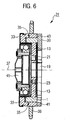
- Fig. 6 is a camshaft adjusting device 31 for an internal combustion engine with the driven wheel 1 and the adapter 13 according to the Fig. 3 to 5 shown in a longitudinal section. Because in the Fig. 1 to 5 both the output gear 1 and the adapter 13 have already been described in detail, reference is made to this point.
- the camshaft adjuster 31 has a drive wheel 33, which, like the Abtreibsteil 1 is formed as a ring gear.
- the drive wheel 33 is mounted on the output gear 1 via a plain bearing 35.
- the two components are arranged rotatable relative to each other about a common axis of rotation 37.
- the drive of the camshaft adjuster 31 takes place in operation via the drive wheel 33 and a crankshaft, not shown.
- the drive wheel 33 is designed for this purpose as a sprocket 38 and can be rotatably connected via a chain with a crankshaft.
- the torque is transmitted via an adjusting motor, not shown, to the drive wheel 33 and the output gear 1 and thus transmit the camshaft. In this way, a targeted adjustment of the phase angle between the camshaft and the crankshaft is achieved.
- the camshaft adjusting device 31 has a stopper component 39 designed as a stop ring, which is mounted axially against the drive wheel 33.
- the abutment component 39 is formed with a stop face 41 for the camshaft, whereby a rotational angle limit between the drive wheel 33 and the driven by means of the adapter 13 rotatably connected to the camshaft output shaft 1 is achieved.
- the abutment component 39 is welded to the drive wheel 33 at its axial contact surface 43 and rotatably connected thereto.
- the individual components of the camshaft adjusting device 31 are finally fixed to each other by means of a central screw 45, wherein the central screw 45 extends through the central bore 19 of the adapter 13.
Landscapes
- Engineering & Computer Science (AREA)
- General Engineering & Computer Science (AREA)
- Mechanical Engineering (AREA)
- Chemical & Material Sciences (AREA)
- Combustion & Propulsion (AREA)
- Valve-Gear Or Valve Arrangements (AREA)
- Valve Device For Special Equipments (AREA)
Claims (8)
- Dispositif de réglage d'arbre à cames (31) pour un moteur à combustion interne, comprenant une roue d'entraînement (33) pouvant être connectée de manière solidaire en rotation à un vilebrequin, une roue de sortie (1) à denture interne disposée de manière à pouvoir tourner autour d'un axe de rotation (37) par rapport à la roue d'entraînement, ainsi qu'un adaptateur (13), qui est disposé sur la périphérie interne (3) de la roue de sortie (1) et par le biais duquel la roue de sortie (1) peut être connectée de manière solidaire en rotation à un arbre à cames,
caractérisé en ce que
l'adaptateur (13) est fixé par le biais de la denture interne (5) à la périphérie interne (3) de la roue de sortie (1). - Dispositif de réglage d'arbre à cames (31) selon la revendication 1,
caractérisé en ce que
l'adaptateur (13) est pressé sur le cercle de tête (11) de la denture interne (5) dans la roue de sortie (1). - Dispositif de réglage d'arbre à cames (31) selon la revendication 1 ou 2,
caractérisé en ce que
la denture interne (5) est réalisée sous forme continue axialement sur la roue de sortie (1). - Dispositif de réglage d'arbre à cames (31) selon l'une quelconque des revendications précédentes,
caractérisé en ce que
l'adaptateur (13) est soudé à la roue de sortie (1). - Dispositif de réglage d'arbre à cames (31) selon l'une quelconque des revendications précédentes,
caractérisé en ce que
l'adaptateur (13) est réalisé sous forme de couvercle de terminaison. - Dispositif de réglage d'arbre à cames (31) selon l'une quelconque des revendications précédentes,
caractérisé en ce que
la roue d'entraînement (33) est réalisée sous forme de couronne et est supportée sur la roue de sortie (1). - Dispositif de réglage d'arbre à cames (31) selon l'une quelconque des revendications précédentes,
caractérisé en ce
qu'un composant de butée (39) pour un arbre à cames est prévu, lequel est contrebalancé axialement sur la roue d'entraînement (33). - Dispositif de réglage d'arbre à cames (31) selon la revendication 8,
caractérisé en ce que
le composant de butée (39) et la roue d'entraînement (33) sont au moins en partie soudés l'un à l'autre.
Applications Claiming Priority (2)
| Application Number | Priority Date | Filing Date | Title |
|---|---|---|---|
| DE102010051051A DE102010051051A1 (de) | 2010-11-11 | 2010-11-11 | Nockenwellenversteller für eine Brennkraftmaschine |
| PCT/EP2011/064479 WO2012062492A1 (fr) | 2010-11-11 | 2011-08-23 | Dispositif de réglage d'arbre à cames pour moteur à combustion interne |
Publications (2)
| Publication Number | Publication Date |
|---|---|
| EP2638256A1 EP2638256A1 (fr) | 2013-09-18 |
| EP2638256B1 true EP2638256B1 (fr) | 2014-07-16 |
Family
ID=44509366
Family Applications (1)
| Application Number | Title | Priority Date | Filing Date |
|---|---|---|---|
| EP11748378.4A Not-in-force EP2638256B1 (fr) | 2010-11-11 | 2011-08-23 | Dispositif de réglage d'arbre à cames pour moteur à combustion interne |
Country Status (6)
| Country | Link |
|---|---|
| US (1) | US20130180484A1 (fr) |
| EP (1) | EP2638256B1 (fr) |
| KR (1) | KR101831012B1 (fr) |
| CN (1) | CN103201468B (fr) |
| DE (1) | DE102010051051A1 (fr) |
| WO (1) | WO2012062492A1 (fr) |
Families Citing this family (2)
| Publication number | Priority date | Publication date | Assignee | Title |
|---|---|---|---|---|
| DE102014221192A1 (de) | 2014-10-20 | 2016-04-21 | Schaeffler Technologies AG & Co. KG | Nockenwellenversteller |
| DE102018127858B3 (de) * | 2018-11-08 | 2020-03-26 | Schaeffler Technologies AG & Co. KG | Wellgetriebe und Verfahren zur Herstellung eines Wellgetriebes |
Family Cites Families (9)
| Publication number | Priority date | Publication date | Assignee | Title |
|---|---|---|---|---|
| US5417186A (en) * | 1993-06-28 | 1995-05-23 | Clemson University | Dual-acting apparatus for variable valve timing and the like |
| DE10248355A1 (de) * | 2002-10-17 | 2004-04-29 | Ina-Schaeffler Kg | Nockenwellenversteller mit elektrischem Antrieb |
| DE10323705B4 (de) * | 2003-05-22 | 2017-03-16 | Daimler Ag | Vorrichtung zum geregelten Verstellen der relativen Drehlage zwischen einer Kurbelwelle und einer Nockenwelle |
| DE102004009128A1 (de) * | 2004-02-25 | 2005-09-15 | Ina-Schaeffler Kg | Elektrischer Nockenwellenversteller |
| DE102005018956A1 (de) * | 2005-04-23 | 2006-11-23 | Schaeffler Kg | Vorrichtung zur Nockenwellenverstellung einer Brennkraftmaschine |
| DE102005059884A1 (de) * | 2005-12-15 | 2007-07-05 | Schaeffler Kg | Nockenwellenversteller |
| DE102008019586A1 (de) | 2008-04-18 | 2009-10-22 | Schaeffler Kg | Nockenwellenverstellvorrichtung |
| US8424500B2 (en) * | 2009-08-06 | 2013-04-23 | Delphi Technologies, Inc. | Harmonic drive camshaft phaser with improved radial stability |
| DE102009037403B4 (de) * | 2009-08-13 | 2018-01-11 | Schaeffler Technologies AG & Co. KG | Elektrischer Nockenwellenversteller |
-
2010
- 2010-11-11 DE DE102010051051A patent/DE102010051051A1/de not_active Withdrawn
-
2011
- 2011-08-23 EP EP11748378.4A patent/EP2638256B1/fr not_active Not-in-force
- 2011-08-23 US US13/823,783 patent/US20130180484A1/en not_active Abandoned
- 2011-08-23 KR KR1020137012235A patent/KR101831012B1/ko not_active Expired - Fee Related
- 2011-08-23 WO PCT/EP2011/064479 patent/WO2012062492A1/fr not_active Ceased
- 2011-08-23 CN CN201180054416.6A patent/CN103201468B/zh not_active Expired - Fee Related
Also Published As
| Publication number | Publication date |
|---|---|
| KR101831012B1 (ko) | 2018-02-21 |
| EP2638256A1 (fr) | 2013-09-18 |
| CN103201468A (zh) | 2013-07-10 |
| DE102010051051A1 (de) | 2012-05-16 |
| US20130180484A1 (en) | 2013-07-18 |
| CN103201468B (zh) | 2015-07-01 |
| KR20130125768A (ko) | 2013-11-19 |
| WO2012062492A1 (fr) | 2012-05-18 |
Similar Documents
| Publication | Publication Date | Title |
|---|---|---|
| DE102010006392B3 (de) | Spannungswellengetriebe und Nockenwellenversteller mit Spannungswellengetriebe | |
| DE102008021220B4 (de) | Vorrichtung zur Phasenverschiebung des Drehwinkels eines Antriebsrades zu einer Abtriebswelle | |
| EP2047143B1 (fr) | Entrainement de pompe d'une boite de vitesses automatique | |
| DE102007017897A1 (de) | Verstellbare Nockenwelle | |
| DE102009013996A1 (de) | Einrichtung zur Verstellung der Exzentrizität für ein Kurbel-CVT-Getriebe | |
| DE102010004289A1 (de) | Mechanische variable Nockenwellenzeitsteuervorrichtung | |
| EP3404294A1 (fr) | Engrenage, en particulier pour générateurs éoliens | |
| EP2744986B1 (fr) | Systeme d'arbre a cames ajustable | |
| DE102012207250A1 (de) | Spielarmes Planetengetriebe | |
| DE102013018775A1 (de) | Triebstock-Getriebeeinrichtung | |
| DE102004061817A1 (de) | Getriebevorrichtung, insbesondere Planetengetriebe mit verbessertem Aufbau | |
| DE10315151A1 (de) | Vorrichtung zur relativen Winkelverstellung einer Nockenwelle gegenüber dem antreibenden Antriebsrad | |
| DE102012203383B3 (de) | Filteranordnung eines Steuerventils für einen Nockenwellenversteller | |
| EP2638256B1 (fr) | Dispositif de réglage d'arbre à cames pour moteur à combustion interne | |
| EP2616644B1 (fr) | Dispositif de déphasage de l'angle de rotation d'un pignon d'entrée par rapport à un pignon de sortie | |
| DE10054798A1 (de) | Elektrisch angetriebene Vorrichtung zur Drehwinkelverstellung einer Welle gegenüber ihrem Antrieb | |
| DE102008046821B4 (de) | Kurbelwelle für eine Brennkraftmaschine mit varibaler Verdichtung und Brennkraftmaschine mit variabler Verdichtung | |
| DE102008009869A1 (de) | Kurbelwelle, insbesondere für eine Brennkraftmaschine | |
| DE102004007052A1 (de) | Verstelleinrichtung für eine Welle | |
| WO2006024371A1 (fr) | Ajusteur d'arbre a cames | |
| WO2015021984A1 (fr) | Déphaseur d'arbre a cames | |
| DE10058012A1 (de) | Zahnradförderpumpe, insbesondere zum Fördern von Kraftstoff zu einer Kraftstoffhochdruckpumpe | |
| DE102011119285A1 (de) | Verstellantrieb | |
| DE102012214762B4 (de) | Befestigungsanordnung zur Verbindung eines Nockenwellenverstellers mit einer Nockenwelle | |
| DE102021114625B4 (de) | Stellgetriebe und Verfahren zur Montage eines Stellgetriebes eines elektromechanischen Nockenwellenverstellers |
Legal Events
| Date | Code | Title | Description |
|---|---|---|---|
| PUAI | Public reference made under article 153(3) epc to a published international application that has entered the european phase |
Free format text: ORIGINAL CODE: 0009012 |
|
| 17P | Request for examination filed |
Effective date: 20130611 |
|
| AK | Designated contracting states |
Kind code of ref document: A1 Designated state(s): AL AT BE BG CH CY CZ DE DK EE ES FI FR GB GR HR HU IE IS IT LI LT LU LV MC MK MT NL NO PL PT RO RS SE SI SK SM TR |
|
| DAX | Request for extension of the european patent (deleted) | ||
| REG | Reference to a national code |
Ref country code: DE Ref legal event code: R079 Ref document number: 502011003785 Country of ref document: DE Free format text: PREVIOUS MAIN CLASS: F01L0001352000 Ipc: F01L0001344000 |
|
| RAP1 | Party data changed (applicant data changed or rights of an application transferred) |
Owner name: SCHAEFFLER TECHNOLOGIES GMBH & CO. KG |
|
| RIC1 | Information provided on ipc code assigned before grant |
Ipc: F01L 1/352 20060101ALI20140303BHEP Ipc: F01L 1/344 20060101AFI20140303BHEP |
|
| GRAP | Despatch of communication of intention to grant a patent |
Free format text: ORIGINAL CODE: EPIDOSNIGR1 |
|
| INTG | Intention to grant announced |
Effective date: 20140422 |
|
| GRAS | Grant fee paid |
Free format text: ORIGINAL CODE: EPIDOSNIGR3 |
|
| GRAA | (expected) grant |
Free format text: ORIGINAL CODE: 0009210 |
|
| AK | Designated contracting states |
Kind code of ref document: B1 Designated state(s): AL AT BE BG CH CY CZ DE DK EE ES FI FR GB GR HR HU IE IS IT LI LT LU LV MC MK MT NL NO PL PT RO RS SE SI SK SM TR |
|
| REG | Reference to a national code |
Ref country code: GB Ref legal event code: FG4D Free format text: NOT ENGLISH |
|
| REG | Reference to a national code |
Ref country code: CH Ref legal event code: EP |
|
| REG | Reference to a national code |
Ref country code: IE Ref legal event code: FG4D Free format text: LANGUAGE OF EP DOCUMENT: GERMAN |
|
| REG | Reference to a national code |
Ref country code: AT Ref legal event code: REF Ref document number: 677805 Country of ref document: AT Kind code of ref document: T Effective date: 20140815 |
|
| REG | Reference to a national code |
Ref country code: DE Ref legal event code: R096 Ref document number: 502011003785 Country of ref document: DE Effective date: 20140828 |
|
| REG | Reference to a national code |
Ref country code: NL Ref legal event code: VDEP Effective date: 20140716 |
|
| REG | Reference to a national code |
Ref country code: LT Ref legal event code: MG4D |
|
| PG25 | Lapsed in a contracting state [announced via postgrant information from national office to epo] |
Ref country code: ES Free format text: LAPSE BECAUSE OF FAILURE TO SUBMIT A TRANSLATION OF THE DESCRIPTION OR TO PAY THE FEE WITHIN THE PRESCRIBED TIME-LIMIT Effective date: 20140716 Ref country code: FI Free format text: LAPSE BECAUSE OF FAILURE TO SUBMIT A TRANSLATION OF THE DESCRIPTION OR TO PAY THE FEE WITHIN THE PRESCRIBED TIME-LIMIT Effective date: 20140716 Ref country code: BG Free format text: LAPSE BECAUSE OF FAILURE TO SUBMIT A TRANSLATION OF THE DESCRIPTION OR TO PAY THE FEE WITHIN THE PRESCRIBED TIME-LIMIT Effective date: 20141016 Ref country code: PT Free format text: LAPSE BECAUSE OF FAILURE TO SUBMIT A TRANSLATION OF THE DESCRIPTION OR TO PAY THE FEE WITHIN THE PRESCRIBED TIME-LIMIT Effective date: 20141117 Ref country code: GR Free format text: LAPSE BECAUSE OF FAILURE TO SUBMIT A TRANSLATION OF THE DESCRIPTION OR TO PAY THE FEE WITHIN THE PRESCRIBED TIME-LIMIT Effective date: 20141017 Ref country code: SE Free format text: LAPSE BECAUSE OF FAILURE TO SUBMIT A TRANSLATION OF THE DESCRIPTION OR TO PAY THE FEE WITHIN THE PRESCRIBED TIME-LIMIT Effective date: 20140716 Ref country code: LT Free format text: LAPSE BECAUSE OF FAILURE TO SUBMIT A TRANSLATION OF THE DESCRIPTION OR TO PAY THE FEE WITHIN THE PRESCRIBED TIME-LIMIT Effective date: 20140716 Ref country code: NO Free format text: LAPSE BECAUSE OF FAILURE TO SUBMIT A TRANSLATION OF THE DESCRIPTION OR TO PAY THE FEE WITHIN THE PRESCRIBED TIME-LIMIT Effective date: 20141016 |
|
| PG25 | Lapsed in a contracting state [announced via postgrant information from national office to epo] |
Ref country code: IS Free format text: LAPSE BECAUSE OF FAILURE TO SUBMIT A TRANSLATION OF THE DESCRIPTION OR TO PAY THE FEE WITHIN THE PRESCRIBED TIME-LIMIT Effective date: 20141116 Ref country code: NL Free format text: LAPSE BECAUSE OF FAILURE TO SUBMIT A TRANSLATION OF THE DESCRIPTION OR TO PAY THE FEE WITHIN THE PRESCRIBED TIME-LIMIT Effective date: 20140716 Ref country code: RS Free format text: LAPSE BECAUSE OF FAILURE TO SUBMIT A TRANSLATION OF THE DESCRIPTION OR TO PAY THE FEE WITHIN THE PRESCRIBED TIME-LIMIT Effective date: 20140716 Ref country code: PL Free format text: LAPSE BECAUSE OF FAILURE TO SUBMIT A TRANSLATION OF THE DESCRIPTION OR TO PAY THE FEE WITHIN THE PRESCRIBED TIME-LIMIT Effective date: 20140716 Ref country code: CY Free format text: LAPSE BECAUSE OF FAILURE TO SUBMIT A TRANSLATION OF THE DESCRIPTION OR TO PAY THE FEE WITHIN THE PRESCRIBED TIME-LIMIT Effective date: 20140716 Ref country code: LV Free format text: LAPSE BECAUSE OF FAILURE TO SUBMIT A TRANSLATION OF THE DESCRIPTION OR TO PAY THE FEE WITHIN THE PRESCRIBED TIME-LIMIT Effective date: 20140716 |
|
| RAP2 | Party data changed (patent owner data changed or rights of a patent transferred) |
Owner name: SCHAEFFLER TECHNOLOGIES AG & CO. KG |
|
| REG | Reference to a national code |
Ref country code: CH Ref legal event code: PL |
|
| REG | Reference to a national code |
Ref country code: DE Ref legal event code: R097 Ref document number: 502011003785 Country of ref document: DE |
|
| PG25 | Lapsed in a contracting state [announced via postgrant information from national office to epo] |
Ref country code: RO Free format text: LAPSE BECAUSE OF FAILURE TO SUBMIT A TRANSLATION OF THE DESCRIPTION OR TO PAY THE FEE WITHIN THE PRESCRIBED TIME-LIMIT Effective date: 20140716 Ref country code: DK Free format text: LAPSE BECAUSE OF FAILURE TO SUBMIT A TRANSLATION OF THE DESCRIPTION OR TO PAY THE FEE WITHIN THE PRESCRIBED TIME-LIMIT Effective date: 20140716 Ref country code: IT Free format text: LAPSE BECAUSE OF FAILURE TO SUBMIT A TRANSLATION OF THE DESCRIPTION OR TO PAY THE FEE WITHIN THE PRESCRIBED TIME-LIMIT Effective date: 20140716 Ref country code: LI Free format text: LAPSE BECAUSE OF NON-PAYMENT OF DUE FEES Effective date: 20140831 Ref country code: CH Free format text: LAPSE BECAUSE OF NON-PAYMENT OF DUE FEES Effective date: 20140831 Ref country code: CZ Free format text: LAPSE BECAUSE OF FAILURE TO SUBMIT A TRANSLATION OF THE DESCRIPTION OR TO PAY THE FEE WITHIN THE PRESCRIBED TIME-LIMIT Effective date: 20140716 Ref country code: MC Free format text: LAPSE BECAUSE OF FAILURE TO SUBMIT A TRANSLATION OF THE DESCRIPTION OR TO PAY THE FEE WITHIN THE PRESCRIBED TIME-LIMIT Effective date: 20140716 Ref country code: BE Free format text: LAPSE BECAUSE OF NON-PAYMENT OF DUE FEES Effective date: 20140831 Ref country code: SK Free format text: LAPSE BECAUSE OF FAILURE TO SUBMIT A TRANSLATION OF THE DESCRIPTION OR TO PAY THE FEE WITHIN THE PRESCRIBED TIME-LIMIT Effective date: 20140716 Ref country code: EE Free format text: LAPSE BECAUSE OF FAILURE TO SUBMIT A TRANSLATION OF THE DESCRIPTION OR TO PAY THE FEE WITHIN THE PRESCRIBED TIME-LIMIT Effective date: 20140716 |
|
| REG | Reference to a national code |
Ref country code: DE Ref legal event code: R081 Ref document number: 502011003785 Country of ref document: DE Owner name: SCHAEFFLER TECHNOLOGIES AG & CO. KG, DE Free format text: FORMER OWNER: SCHAEFFLER TECHNOLOGIES GMBH & CO. KG, 91074 HERZOGENAURACH, DE Effective date: 20150408 |
|
| REG | Reference to a national code |
Ref country code: IE Ref legal event code: MM4A |
|
| PLBE | No opposition filed within time limit |
Free format text: ORIGINAL CODE: 0009261 |
|
| STAA | Information on the status of an ep patent application or granted ep patent |
Free format text: STATUS: NO OPPOSITION FILED WITHIN TIME LIMIT |
|
| REG | Reference to a national code |
Ref country code: FR Ref legal event code: ST Effective date: 20150430 |
|
| 26N | No opposition filed |
Effective date: 20150417 |
|
| PG25 | Lapsed in a contracting state [announced via postgrant information from national office to epo] |
Ref country code: FR Free format text: LAPSE BECAUSE OF NON-PAYMENT OF DUE FEES Effective date: 20140916 Ref country code: IE Free format text: LAPSE BECAUSE OF NON-PAYMENT OF DUE FEES Effective date: 20140823 |
|
| PG25 | Lapsed in a contracting state [announced via postgrant information from national office to epo] |
Ref country code: SI Free format text: LAPSE BECAUSE OF FAILURE TO SUBMIT A TRANSLATION OF THE DESCRIPTION OR TO PAY THE FEE WITHIN THE PRESCRIBED TIME-LIMIT Effective date: 20140716 |
|
| GBPC | Gb: european patent ceased through non-payment of renewal fee |
Effective date: 20150823 |
|
| PG25 | Lapsed in a contracting state [announced via postgrant information from national office to epo] |
Ref country code: SM Free format text: LAPSE BECAUSE OF FAILURE TO SUBMIT A TRANSLATION OF THE DESCRIPTION OR TO PAY THE FEE WITHIN THE PRESCRIBED TIME-LIMIT Effective date: 20140716 |
|
| PG25 | Lapsed in a contracting state [announced via postgrant information from national office to epo] |
Ref country code: MT Free format text: LAPSE BECAUSE OF FAILURE TO SUBMIT A TRANSLATION OF THE DESCRIPTION OR TO PAY THE FEE WITHIN THE PRESCRIBED TIME-LIMIT Effective date: 20140716 |
|
| PG25 | Lapsed in a contracting state [announced via postgrant information from national office to epo] |
Ref country code: LU Free format text: LAPSE BECAUSE OF NON-PAYMENT OF DUE FEES Effective date: 20140823 Ref country code: HU Free format text: LAPSE BECAUSE OF FAILURE TO SUBMIT A TRANSLATION OF THE DESCRIPTION OR TO PAY THE FEE WITHIN THE PRESCRIBED TIME-LIMIT; INVALID AB INITIO Effective date: 20110823 Ref country code: HR Free format text: LAPSE BECAUSE OF FAILURE TO SUBMIT A TRANSLATION OF THE DESCRIPTION OR TO PAY THE FEE WITHIN THE PRESCRIBED TIME-LIMIT Effective date: 20140716 Ref country code: GB Free format text: LAPSE BECAUSE OF NON-PAYMENT OF DUE FEES Effective date: 20150823 |
|
| PG25 | Lapsed in a contracting state [announced via postgrant information from national office to epo] |
Ref country code: TR Free format text: LAPSE BECAUSE OF FAILURE TO SUBMIT A TRANSLATION OF THE DESCRIPTION OR TO PAY THE FEE WITHIN THE PRESCRIBED TIME-LIMIT Effective date: 20140716 |
|
| REG | Reference to a national code |
Ref country code: AT Ref legal event code: MM01 Ref document number: 677805 Country of ref document: AT Kind code of ref document: T Effective date: 20160823 |
|
| PG25 | Lapsed in a contracting state [announced via postgrant information from national office to epo] |
Ref country code: AT Free format text: LAPSE BECAUSE OF NON-PAYMENT OF DUE FEES Effective date: 20160823 |
|
| PG25 | Lapsed in a contracting state [announced via postgrant information from national office to epo] |
Ref country code: MK Free format text: LAPSE BECAUSE OF FAILURE TO SUBMIT A TRANSLATION OF THE DESCRIPTION OR TO PAY THE FEE WITHIN THE PRESCRIBED TIME-LIMIT Effective date: 20140716 |
|
| PG25 | Lapsed in a contracting state [announced via postgrant information from national office to epo] |
Ref country code: AL Free format text: LAPSE BECAUSE OF FAILURE TO SUBMIT A TRANSLATION OF THE DESCRIPTION OR TO PAY THE FEE WITHIN THE PRESCRIBED TIME-LIMIT Effective date: 20140716 |
|
| PGFP | Annual fee paid to national office [announced via postgrant information from national office to epo] |
Ref country code: DE Payment date: 20211020 Year of fee payment: 11 |
|
| REG | Reference to a national code |
Ref country code: DE Ref legal event code: R119 Ref document number: 502011003785 Country of ref document: DE |
|
| P01 | Opt-out of the competence of the unified patent court (upc) registered |
Effective date: 20230522 |
|
| PG25 | Lapsed in a contracting state [announced via postgrant information from national office to epo] |
Ref country code: DE Free format text: LAPSE BECAUSE OF NON-PAYMENT OF DUE FEES Effective date: 20230301 |