EP2638264B1 - Appareil et procédé de détermination d'anomalie d'un capteur de température pour liquide de refroidissement, et système de refroidissement de moteur - Google Patents
Appareil et procédé de détermination d'anomalie d'un capteur de température pour liquide de refroidissement, et système de refroidissement de moteur Download PDFInfo
- Publication number
- EP2638264B1 EP2638264B1 EP11817235.2A EP11817235A EP2638264B1 EP 2638264 B1 EP2638264 B1 EP 2638264B1 EP 11817235 A EP11817235 A EP 11817235A EP 2638264 B1 EP2638264 B1 EP 2638264B1
- Authority
- EP
- European Patent Office
- Prior art keywords
- coolant
- coolant temperature
- bypass
- passageway
- temperature sensor
- Prior art date
- Legal status (The legal status is an assumption and is not a legal conclusion. Google has not performed a legal analysis and makes no representation as to the accuracy of the status listed.)
- Not-in-force
Links
- 239000002826 coolant Substances 0.000 title claims description 445
- 230000005856 abnormality Effects 0.000 title claims description 74
- 238000000034 method Methods 0.000 title claims description 41
- 238000001816 cooling Methods 0.000 title claims description 34
- 238000011084 recovery Methods 0.000 claims description 23
- 230000002159 abnormal effect Effects 0.000 claims description 20
- 238000002156 mixing Methods 0.000 claims description 5
- 239000000203 mixture Substances 0.000 description 7
- 238000002474 experimental method Methods 0.000 description 6
- 238000004088 simulation Methods 0.000 description 6
- 230000006835 compression Effects 0.000 description 5
- 238000007906 compression Methods 0.000 description 5
- 238000010586 diagram Methods 0.000 description 4
- 238000010438 heat treatment Methods 0.000 description 3
- 230000006978 adaptation Effects 0.000 description 2
- 238000004364 calculation method Methods 0.000 description 2
- 238000002485 combustion reaction Methods 0.000 description 2
- 238000010276 construction Methods 0.000 description 2
- 230000008602 contraction Effects 0.000 description 2
- 238000001514 detection method Methods 0.000 description 2
- 238000011144 upstream manufacturing Methods 0.000 description 2
- 230000005540 biological transmission Effects 0.000 description 1
- 230000000694 effects Effects 0.000 description 1
- 238000005516 engineering process Methods 0.000 description 1
- 239000012530 fluid Substances 0.000 description 1
- 239000000446 fuel Substances 0.000 description 1
- 238000007654 immersion Methods 0.000 description 1
- 238000002347 injection Methods 0.000 description 1
- 239000007924 injection Substances 0.000 description 1
- 239000000155 melt Substances 0.000 description 1
- 238000002844 melting Methods 0.000 description 1
- 230000008018 melting Effects 0.000 description 1
- 238000010992 reflux Methods 0.000 description 1
- 230000000717 retained effect Effects 0.000 description 1
- XLYOFNOQVPJJNP-UHFFFAOYSA-N water Substances O XLYOFNOQVPJJNP-UHFFFAOYSA-N 0.000 description 1
Images


Classifications
-
- F—MECHANICAL ENGINEERING; LIGHTING; HEATING; WEAPONS; BLASTING
- F01—MACHINES OR ENGINES IN GENERAL; ENGINE PLANTS IN GENERAL; STEAM ENGINES
- F01P—COOLING OF MACHINES OR ENGINES IN GENERAL; COOLING OF INTERNAL-COMBUSTION ENGINES
- F01P11/00—Component parts, details, or accessories not provided for in, or of interest apart from, groups F01P1/00 - F01P9/00
- F01P11/14—Indicating devices; Other safety devices
- F01P11/18—Indicating devices; Other safety devices concerning coolant pressure, coolant flow, or liquid-coolant level
-
- F—MECHANICAL ENGINEERING; LIGHTING; HEATING; WEAPONS; BLASTING
- F01—MACHINES OR ENGINES IN GENERAL; ENGINE PLANTS IN GENERAL; STEAM ENGINES
- F01P—COOLING OF MACHINES OR ENGINES IN GENERAL; COOLING OF INTERNAL-COMBUSTION ENGINES
- F01P7/00—Controlling of coolant flow
- F01P7/14—Controlling of coolant flow the coolant being liquid
- F01P7/16—Controlling of coolant flow the coolant being liquid by thermostatic control
- F01P7/165—Controlling of coolant flow the coolant being liquid by thermostatic control characterised by systems with two or more loops
-
- F—MECHANICAL ENGINEERING; LIGHTING; HEATING; WEAPONS; BLASTING
- F01—MACHINES OR ENGINES IN GENERAL; ENGINE PLANTS IN GENERAL; STEAM ENGINES
- F01P—COOLING OF MACHINES OR ENGINES IN GENERAL; COOLING OF INTERNAL-COMBUSTION ENGINES
- F01P2025/00—Measuring
- F01P2025/08—Temperature
- F01P2025/32—Engine outcoming fluid temperature
Definitions
- the invention relates to a cooling system of an engine (internal combustion engine) and, more particularly, to a coolant temperature sensor abnormality determination apparatus and a coolant temperature sensor abnormality determination method that determine the presence or absence of abnormality of a coolant temperature sensor of the cooling system.
- a coolant jacket as a coolant passageway is provided in the engine (a cylinder block or a cylinder head), and the entire engine is cooled (or warmed) by circulating a coolant via the coolant jacket by a coolant pump.
- a changeover valve that restricts the circulation of the coolant between an engine coolant passageway and a heater system (heater passageway) is provided, and while the engine is cold, the changeover valve is closed to stop passage of the coolant within the engine (within the coolant jacket) (to perform an in-engine coolant stop) so that quick warm-up of the engine is accomplished (e.g., see Japanese Patent Application Publication No. 2009-150266 ( JP-A-2009-150266 )).
- a cooling system that performs the aforementioned in-engine coolant stop is provided with, for example, an engine coolant temperature sensor that detects the outlet coolant temperature of the engine, and a heater-system coolant temperature sensor (e.g., a heater inlet coolant temperature sensor) that detects the coolant temperature in a heater system.
- a heater-system coolant temperature sensor e.g., a heater inlet coolant temperature sensor
- an abnormality detection method of detecting abnormality of the heater-system coolant temperature sensor there exists a method in which it is determined that the heater-system coolant temperature sensor is abnormal in the case where after elapse of a certain period following the start of the engine, it is found that the detected coolant temperature value detected by the heater-system coolant temperature sensor has not risen by a predetermined value or more (e.g., see Japanese Patent Application Publication No. 10-073047 ( JP-A-10-073047 )).
- an example of the abnormality of the coolant temperature sensor is a stuck abnormality in which the
- the cooling system that performs the aforementioned in-engine coolant stop
- the foregoing abnormality detection method is applied to the abnormality determination regarding the heater-system coolant temperature sensor
- a heat source e.g., an exhaust heat recovery device or the like
- the temperature of the coolant in the heater system does not rise even after a certain period of time elapses following the start of the engine. Therefore, since the detected coolant temperature value provided by the heater-system coolant temperature does not rise, it sometimes happens that the heater-system coolant temperature sensor is falsely determined as being abnormal although the sensor is actually normal.
- the invention provides a coolant temperature sensor abnormality determination apparatus and a coolant temperature sensor abnormality determination method that are capable of precisely determining whether a coolant temperature sensor that detects the temperature of a coolant in a heater system is abnormal without making a false determination, in a cooling system that stops passage of a coolant within an engine.
- a coolant temperature sensor abnormality determination apparatus in accordance with a first aspect of the invention is a coolant temperature sensor abnormality determination apparatus which is applied to an engine cooling system (a cooling system that performs an in-engine coolant stop) that includes an engine coolant passageway, a bypass passageway (heater passageway) that bypasses an engine, a control valve (changeover valve) that restricts circulation of a coolant between the engine coolant passageway and the bypass passageway, and a bypass coolant temperature sensor (heater inlet coolant temperature sensor) that detects bypass coolant temperature in the bypass passageway, and which determines whether the bypass coolant temperature sensor is abnormal, and which includes determination means for opening the control valve if amount of increase of a detected value of the bypass coolant temperature obtained when the bypass coolant temperature is estimated to be equal to or greater than a predetermined value (concretely, for example, when the amount of intake air taken into the engine (the integrated intake air amount value following the time of the start of the engine) becomes equal to or greater than a predetermined value)
- the determination means may determine that the bypass coolant temperature sensor is normal, if the amount of increase in the detected value of the bypass coolant temperature becomes equal to or greater than the predetermined value after the control valve opens that the bypass coolant temperature sensor is normal, if the amount of increase in the detected value of the bypass coolant temperature becomes equal to or greater than the predetermined value after the control valve opens, and the determination means may determine that the bypass coolant temperature sensor is abnormal, if the amount of increase in the detected value of the bypass coolant temperature is smaller than the predetermined value after the control valve opens.
- the bypass passageway may be provided with at least one of an exhaust heat recovery device and an EGR (Exhaust Gas Recirculation) cooler.
- the apparatus determines that the bypass coolant temperature sensor is normal.
- the control valve opens, the coolants from the two systems, that is, the engine coolant passageway and the bypass passageway, circulate through the two systems, and the high-temperature coolant warmed by the engine flows into the bypass passageway.
- This increases the temperature of the coolant in the bypass passageway even if the bypass passageway has no heat source available (even if a heat source, such as an exhaust heat recovery device, an EGR cooler, etc., has a fault), so that the detected bypass coolant temperature value detected by the coolant temperature sensor increases provided that the bypass coolant temperature sensor is normal.
- the apparatus determines that the bypass coolant temperature sensor is normal in the case where the amount of change in the detected bypass coolant temperature value after the control valve opens is greater than or equal to a predetermined value, and determines that the bypass coolant temperature sensor is abnormal (has a stuck abnormality) in the case where the amount of change in the detected bypass coolant temperature value is smaller than a predetermined value.
- the apparatus opens the control valve to allow the high-temperature coolant from the engine to flow into the bypass passageway so that the temperature of the coolant in the bypass passageway increases, and while such a state of increased coolant temperature is maintained, determination regarding the bypass coolant temperature sensor is performed on the basis of the amount of change in the detected bypass coolant temperature value detected by the bypass coolant temperature sensor. Therefore, even if the bypass passageway does not have a heat source available due to a fault of an exhaust heat recovery device, an EGR cooler, etc., the apparatus is able to precisely determine whether the bypass coolant temperature sensor is abnormal without making a false determination.
- the control valve that restricts the circulation of the coolant between the engine coolant passageway and the bypass passageway may be a temperature-sensitive operation valve that has a temperature sensitive portion that displaces a valve body, and the coolant temperature sensor abnormality determination apparatus may determine that the control valve has opened, when an estimated value of ambient coolant temperature of the control valve becomes equal to or greater than a valve-opening temperature of the control valve. Adoption of this construction makes it possible to shorten the time that is needed for determination whether the control valve has opened. This will be explained below.
- a cooling system (a cooling system that performs an in-engine coolant stop) to which the coolant temperature sensor abnormality determination apparatus in accordance with the foregoing aspect uses, for example, a temperature-sensitive operation valve that has a temperature sensitive portion that displaces a valve body, as a control valve provided at a coolant outlet of the engine.
- a temperature-sensitive operation valve that has a temperature sensitive portion that displaces a valve body, as a control valve provided at a coolant outlet of the engine.
- an electric heater is buried in the temperature sensitive portion so that the control valve can also be forced to open by melting the thermo-wax through the use of heat produced by electrifying the electric heater (i.e. to open by electrification of the heater).
- the valve is opened by electrifying the heater when the foregoing amount of increase in the detected bypass coolant temperature value is smaller than the predetermined value.
- An example of the method of determining whether the control valve has opened is a method of determining whether the valve has opened by using the elapse
- an open-valve state criterion value is adapted on the basis of the condition in which it takes the longest time before the control valve is opened.
- the margin is very large, so that there is inevitably a long time before the determination regarding the normality or abnormality of the bypass coolant temperature sensor is performed.
- the coolant temperature sensor abnormality determination apparatus in accordance with the foregoing aspect, if the determination regarding the bypass coolant temperature sensor is performed during a state in which the high-temperature coolant in the engine coolant passageway and the coolant in the bypass passageway are not sufficiently mixed together (a state in which the temperature of the coolant in the bypass passageway has not sufficiently increased) after the control valve has opened, there is a possibility of making a false determination that the sensor is abnormal when the sensor is actually normal.
- the determination regarding the bypass coolant temperature sensor may be executed after elapse of a predetermined time following the opening of the control valve, that is, after elapse of a time that is needed for the coolant temperature in the bypass passageway to sufficiently increase.
- the coolant temperature sensor abnormality determination apparatus in accordance with the foregoing aspect, if the amount of increase in the detected bypass coolant temperature value obtained when the bypass coolant temperature is estimated to be equal to or greater than a predetermined value is relatively small, the control valve is opened to increase the coolant temperature in the bypass passageway, and then the determination regarding abnormality of the coolant temperature sensor is performed on the basis of the amount of change in the detected bypass coolant temperature value after the control valve has opened. Therefore, the presence of abnormality of the bypass coolant temperature sensor can be precisely determined without making a false determination.
- a coolant temperature sensor abnormality determination method in accordance with a second aspect of the invention is a coolant temperature sensor abnormality determination method which is for use in an engine cooling system that includes an engine coolant passageway, a bypass passageway that bypasses an engine, a control valve that restricts circulation of a coolant between the engine coolant passageway and the bypass passageway, and a bypass coolant temperature sensor that detects bypass coolant temperature in the bypass passageway, and which determines whether the bypass coolant temperature sensor is abnormal, and the method includes: detecting the bypass coolant temperature by using the bypass coolant temperature sensor when the bypass coolant temperature is estimated to be equal to or greater than a predetermined value, determining that the bypass coolant temperature sensor is normal if amount of increase in the bypass coolant temperature detected is greater than or equal to the predetermined value; and opening the control valve if the amount of increase in the bypass coolant temperature detected is smaller than the predetermined value, and detecting the bypass coolant temperature again by using the bypass coolant temperature sensor after the control valve opens, and determining whether the bypass coolant
- An engine cooling system in accordance with a third aspect of the invention includes: an engine coolant passageway; a bypass passageway that bypasses an engine; a control valve that restricts circulation of a coolant between the engine coolant passageway and the bypass passageway; a bypass coolant temperature sensor that detects bypass coolant temperature in the bypass passageway; and a coolant temperature sensor abnormality determination portion that opens the control valve if amount of increase of a detected value of the bypass coolant temperature obtained when the bypass coolant temperature is estimated to be equal to or greater than a predetermined value is smaller than the predetermined value, and that determines whether the bypass coolant temperature sensor is abnormal based on amount of change in the detected value of the bypass coolant temperature obtained after the control valve opens.
- the coolant temperature sensor abnormality determination method in accordance with the second aspect and the engine cooling system in accordance with the third aspect it is possible to achieve substantially the same effects as those achieved by the coolant temperature sensor abnormality determination apparatus in accordance with the first aspect.
- a cooling system of an engine 1 (an in-engine coolant stop cooling system) will be described with reference to FIG. 1 .
- the cooling system of this embodiment includes an electric coolant pump 2, a radiator 3, a thermostat 4, a heater 5, an exhaust heat recovery device 6, an EGR (Exhaust Gas Recirculation) cooler 7, a changeover valve 10, a coolant passageway 200 for circulating a coolant to these appliances, etc.
- EGR Exhaust Gas Recirculation
- the coolant passageway 200 includes an engine coolant passageway 201 that circulates the coolant (e.g., LLC (Long Life Coolant)) via the engine 1, the radiator 3 and the thermostat 4, and a heater passageway 202 that circulates the coolant via the EGR cooler 7, the exhaust heat recovery device 6, the heater 5 and the thermostat 4.
- the coolant e.g., LLC (Long Life Coolant)
- the heater passageway 202 that circulates the coolant via the EGR cooler 7, the exhaust heat recovery device 6, the heater 5 and the thermostat 4.
- one electric coolant pump (electric water pump) 2 is employed for both the circulation of the coolant through the engine coolant passageway 201 and the circulation of the coolant through the heater passageway 202.
- the engine 1 is a gasoline engine, a diesel engine, etc., that is mounted in a conventional vehicle, a hybrid vehicle, etc., and a cylinder block and a cylinder head of the engine are provided with a coolant jacket (not shown).
- the engine 1 is provided with an engine coolant temperature sensor 21 that detects the coolant temperature at a coolant outlet (a coolant jacket outlet of the cylinder head) 1b.
- an intake air temperature sensor 23 that detects the temperature of intake air
- an air flow meter 24 that detects the amount of air taken into the engine 1.
- Output signals of the engine coolant temperature sensor 21, the intake air temperature sensor 23 and the air flow meter 24 are input to an ECU (Electronic Control Unit) 300.
- ECU Electronic Control Unit
- the electric coolant pump 2 is a coolant pump whose discharge flow amount (discharge pressure) can be variably set by controlling the rotation speed of an electric motor.
- the electric coolant pump 2 is disposed so that a discharge port thereof communicates with a coolant inlet 1a of the engine 1 (an inlet of the coolant jacket).
- the operation of the electric coolant pump 2 is controlled by the ECU 300. Besides, the electric coolant pump 2 is driven along with the starting of the engine 1, and the discharge flow amount thereof is controlled according to the operation state of the engine 1, and the like.
- the thermostat 4 is a valve device that operates by, for example, expansion and contraction of a thermo-wax of a temperature sensitive portion, and is designed so that when the coolant temperature is relatively low, the coolant passageway between the radiator 3 and the electric coolant pump 2 is shut down so as to keep the coolant from flowing into the radiator 3 (the engine coolant passageway 201).
- the thermostat 4 operates (opens its valve) according to the coolant temperature so as to allow a part of the coolant to flow into the radiator 3, so that heat recovered by the coolant is released from the radiator 3 into the atmosphere.
- the thermostat 4 has been set so as to open when the ambient coolant temperature of the temperature sensitive portion ( ⁇ the wax temperature) reaches a coolant temperature (e.g., 82°C or higher) that is higher than the valve opening temperature of the changeover valve 10 (e.g., 70°C) described later.
- a coolant temperature e.g., 82°C or higher
- the heater passageway 202 is a bypass passageway that bypasses the engine 1.
- the EGR cooler 7, the exhaust heat recovery device 6 and the heater 5 are connected in series on the heater passageway 202, in that order from the upstream side in terms of the flow of the coolant.
- the coolant discharged from the electric coolant pump 2 circulates in the order of "the EGR cooler 7 ⁇ the exhaust heat recovery device 6 ⁇ the heater 5 ⁇ the thermostat 4 ⁇ the electric coolant pump 2".
- a heater connection passageway 202a is connected to the heater passageway 202 between the EGR cooler 7 and the exhaust heat recovery device 6.
- the heater connection passageway 202a is connected, via the changeover valve 10, to a coolant outlet 1b of the engine 1 (a coolant jacket outlet of the cylinder head).
- the changeover valve (control valve) 10 opens and closes the heater connection passageway 202a. Details of the changeover valve 10 will be described later.
- the heater 5 is a heat exchanger for heating a cabin of the vehicle by utilizing heat of the coolant, and is disposed facing a blow duct of the air-conditioner. Specifically, a design is made such that when the cabin is heated (when the heater is on), the air-conditioned air that flows in the blow duct is passed through the heater 5 (a heater core) and the obtained warmed air is supplied into the cabin, and such that in the other times (e.g., during the cooling) (when the heater is off), the air-conditioned air bypasses the heater 5.
- the inlet coolant temperature of the heater 5 is equivalent to the temperature of the coolant that flows in the heater passageway 202 (bypass passageway)
- the heater inlet coolant temperature sensor 22 corresponds to a bypass coolant temperature sensor.
- the exhaust heat recovery device 6 is a heat exchanger that is disposed on an exhaust passageway of the engine 1 for the purpose of recovering heat from the exhaust gas by using the coolant. The heat recovered by the exhaust heat recovery device 6 is utilized for the warm-up of the engine and the heating of the cabin.
- the EGR cooler 7 is a heat exchanger that is disposed on an EGR passageway that returns a part of the exhaust gas that flows in the exhaust passageway of the engine 1 to an intake passageway for the purpose of cooling the EGR gas that passes (refluxes) in the EGR passageway.
- the changeover valve 10 in this embodiment includes a housing 11, a valve body 12, a compression coil spring 13, a temperature sensitive portion 14, etc.
- the housing 11 is provided with a coolant inlet 11a that is connected to the coolant outlet (the coolant jacket opening of the cylinder head) 1b of the engine 1 shown in FIG. 1 , a radiator connection opening 11b that is connected to the radiator 3, and a heater connection opening 11c.
- the heater connection opening 11c is connected to the heater passageway 202 via the heater connection passageway 202a shown in FIG. 1 .
- a valve seat 111 and a spring seat 112 are provided, facing each other.
- a space between the valve seat 111 and the spring seat 112 (a space on an upstream side of the valve body 12) forms a coolant lead-in portion 11d.
- the coolant inlet 11a communicates with the coolant lead-in portion 11d.
- the radiator connection opening 11b communicates with the coolant inlet 11 a.
- a space on a downstream side of the valve body 12 forms a coolant lead-out portion 11e with which the heater connection opening 11c communicates.
- the valve body 12 is disposed between the valve seat 111 and the spring seat 112 inside the housing 11 so as to be able to contact the valve seat 111 and separate therefrom.
- This valve body 12 and a case 141 of the temperature sensitive portion 14 are integrated together.
- the compression coil spring 13 is placed between the valve body 12 and the spring seat 112. Due to the elastic force of the compression coil spring 13, the valve body 12 is urged toward the valve seat 111.
- the temperature sensitive portion (temperature sensitive actuator) 14 includes a case 141 and a rod 142.
- the rod 142 is a rod-shape member extending in the opening-closing direction of the valve body 12, and disposed freely slidably relative to the case 141.
- the rod 142 penetrates the valve body 12.
- the valve body 12 is slidable in the opening-closing direction relative to the rod 142.
- a distal end portion of the rod 142 penetrates a wall body 11f of the housing 11 (a wall body at the opposite side to the coolant inlet 11a), and the distal end portion is retained by a rod retainer member 16.
- thermo-wax 143 that expands and contracts due to changes in the ambient coolant temperature of the temperature sensitive portion 14 (hereinafter, also referred to as changeover valve's ambient coolant temperature) (i.e., changes in the wax temperature).
- the expansion and contraction of the thermo-wax 143 changes the amount of protrusion of the rod 142 relative to the case 141.
- the thermo-wax 143 is housed within a seal member 144 that is made of rubber or the like.
- the changeover valve 10 having a structure as described above, when the changeover valve's ambient coolant temperature ( ⁇ the wax temperature) Tvw is lower than a predetermined value (70°C in this embodiment), there occurs a state in which the amount of protrusion of the rod 142 from the case 141 is small (i.e., the amount of immersion of the rod 142 in the case 141 is large) so that the valve body 12 is seated on the valve seat 111 (i.e., is closed) by the elastic force of the compression coil spring 13 ( FIG. 2A ).
- a predetermined value 70°C in this embodiment
- thermo-wax 143 of the temperature sensitive portion 14 expands. Due to the expansion of the thermo-wax 143, the amount of protrusion of the rod 142 from the case 141 increases, the entire temperature sensitive portion 14, that is, the valve body 12, moves in a direction away from the valve seat 111, overcoming the elastic force of the compression coil spring 13, so that the valve body 12 separates from the valve seat 111 (opens) ( FIG. 2B ).
- the changeover valve 10 in this embodiment assumes a closed state, in which the coolant outlet 1b of the engine 1 (the engine coolant passageway 201) shown in FIG. 1 and the heater passageway 202 shown in FIG. 1 are shut off from each other (the circulation of the coolant between the engine coolant passageway and the bypass passageway is restricted).
- the changeover valve 10 assumes an open valve state, in which the coolant outlet 1b of the engine 1 (the engine coolant passageway 201) and the heater passageway 202 shown in FIG. 1 communicate with each other.
- the thermostat 4 shown in FIG. 1 is in the closed valve state although the coolant inlet 11a and the radiator connection opening 11b communicate with each other, the coolant having flown into the coolant inlet 11a does not flow into the radiator connection opening 11b.
- an electric heater 15 is buried within the temperature sensitive portion 14. By electrifying the electric heater 15 so that heat generated by the electric heater 15 melts the thermo-wax 143, the changeover valve 10 can be forced to assume the open state.
- the opening of the changeover valve 10 due to the heater electrification is performed during a coolant temperature sensor abnormality determination process described later (at the time of the second determination regarding normality of the heater inlet coolant temperature 22), or the like.
- the electric heater 15 of the changeover valve 10 is operated by a changeover valve controller (not shown).
- the changeover valve controller performs electrification of the electric heater 15 of the changeover valve 10 according to a valve opening request from the ECU 300.
- the changeover valve 10 assumes the closed state, so that the passage of the coolant within the engine 1 (within the coolant jacket) is stopped (in-engine coolant stop). Due to this, the engine 1 is quickly warmed up.
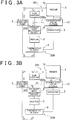
- the changeover valve 10 when the changeover valve 10 is in the closed state, the coolant circulates through the heater passageway 202 as shown in FIG. 3A due to operation of the electric coolant pump 2, and the coolant flows in the sequence of "the electric coolant pump 2 ⁇ the EGR cooler 7 ⁇ the exhaust heat recovery device 6 ⁇ the heater 5 ⁇ the thermostat 4 ⁇ the electric coolant pump 2". If there is a cabin-heating request during the quick warm-up as described above, it suffices that the amount of heat needed for the heater 5 is covered by the heat that is recovered by the exhaust heat recovery device 6.
- the changeover valve 10 opens.
- the coolant flows in the sequence of "the electric coolant pump 2 ⁇ the coolant inlet 1a of the engine 1 ⁇ the inside of the engine 1 (within the coolant jacket) ⁇ the coolant outlet 1b of the engine 1 ⁇ the changeover valve 10 ⁇ the heater connection passageway 202a", in addition to the circulation of the coolant in the heater passageway 202, as shown in FIG. 3B , so that the engine 1 is cooled.
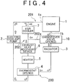
- the changeover valve 10 assumes the open state, the coolant in the engine coolant passageway 201 (in the engine 1) and the coolant in the heater passageway (bypass passageway) 202 are mixed.
- the thermostat 4 operates (opens its valve) so that a portion of the coolant flows into the radiator 3, as shown in FIG. 4 , and therefore heat recovered by the coolant is released from the radiator 3 into the atmosphere.
- the ECU 300 includes a CPU, a ROM, a RAM, a back-up RAM, etc.
- the ROM stores various control programs, maps that are referred to at the time of execution of the various control programs, etc.
- the CPU executes computation processes on the basis of the various control programs or maps stored in the ROM.
- the RAM is a memory for temporarily storing results of computations by the CPU, data input from various sensors, etc.
- the back-up RAM is a non-volatile memory for storing data or the like that needs to be stored, when the engine 1 is stopped.
- the ECU 300 is connected to various sensors that detect states of operation of the engine 1, including the engine coolant temperature sensor 21, the intake air temperature sensor 23 and the air flow meter 24, as shown in FIG. 1 . Besides, the ECU 300 is also connected to the heater inlet coolant temperature sensor 22, an ignition switch (not shown), etc.
- the ECU 300 on the basis of output signals from various sensors that detect the states of operation of the engine, executes various controls of the engine 1 that include an opening degree control of a throttle valve of the engine 1, a fuel injection amount control (an opening/closing control of injectors), etc. Besides, the ECU 300 also executes a "coolant temperature sensor abnormality determination process" described below.
- the process routine shown in FIG. 5 is executed by the ECU 300.
- the process routine shown in FIG. 5 is started at the time point (IG-ON) when the ignition switch is turned on.
- the ECU 300 firstly in step ST101, picks the heater inlet coolant temperature thw2 occurring at the time of start of the engine from the output signal of the heater inlet coolant temperature sensor 22.
- the ECU 300 reads in an abnormality determination value ⁇ (°C) for use in the determination processes of step ST105 and step ST110 that are described later.
- the abnormality determination value ⁇ (constant value) or a map for calculating the abnormality determination value ⁇ is stored in the ROM of the ECU 300.
- step ST103 ECU 300 calculates an integrated value ( ⁇ ga) of the amount of intake air from the time of start of the engine, on the basis of the output signal of the air flow meter 24.
- step ST104 the ECU 300 determines whether the integrated intake air amount value ( ⁇ ga) is greater than or equal to a prescribed value ⁇ [g]. At the time point when the result of the determination is found to be an affirmative determination (YES) (the time point when the state of ⁇ ga ⁇ [g] is reached), the ECU 300 determines that a pre-determination condition is satisfied, and then proceeds to step ST105.
- YES affirmative determination
- step ST105 the ECU 300 calculates a deviation of the heater inlet coolant temperature thw2 (detected value) (i.e., a deviation thereof (thw2 deviation) from the detected heater inlet coolant temperature value obtained at the time of start of the engine)) on the basis of the output signal of the heater inlet coolant temperature sensor 22 obtained when the integrated intake air amount value ( ⁇ ga) becomes equal to or greater than the prescribed value ⁇ [g], and then determines whether the thw2 deviation is greater than or equal to the abnormality determination value ⁇ [°C] read in in step ST102 (the first normality determination to be made).
- thw2 detected value
- step ST 111 If the result of the determination is an affirmative determination (YES) (if thw2 deviation ⁇ ), the ECU 300 determines that the heater inlet coolant temperature sensor 22 is normal (step ST 111). If the result of the determination in step ST105 is a negative determination (NO) (if thw2 deviation ⁇ ), the ECU 300 proceeds to step ST106.
- step ST105 if the result of the determination in step ST105 is a negative determination (NO), the ECU 300 cannot determine whether there exists a situation in which "the heater inlet coolant temperature sensor 22 is abnormal" or a situation in which "the exhaust heat recovery device 6 or the EGR cooler 7 has a fault". Therefore, in this example, after the changeover valve 10 is forced to be opened, the second normality determination regarding the heater inlet coolant temperature sensor 22 is performed, as described later.
- step ST106 the ECU 300 starts electrification of the electric heater 15 of the changeover valve 10 by outputting a valve opening request to the changeover valve controller.
- the ECU 300 counts the elapsed time from the time point of starting electrification of the electric heater 15 of the changeover valve 10.
- step ST107 the ECU 300 determines whether "the changeover valve is free of a closed-state fault". If the result of the determination is an affirmative determination (YES), the ECU 300 proceeds to step ST108. If the result of the determination in step ST107 is a negative determination (NO), the ECU 300 does not perform the determination regarding the normality or abnormality of the heater inlet coolant temperature sensor 22 (step ST113, in which the determination is skipped).
- the term "closed-state fault” herein refers to a fault in which the valve is in a closed state and is not able to be opened.
- step ST107 An example of the determination process of step ST107 will be concretely described.
- the changeover valve 10 has the closed-state fault
- the coolant in the engine 1 remains still even if the heater 15 is electrified, and therefore the amount of increase in the engine coolant temperature thw1 detected by the engine coolant temperature sensor 21 is large.
- the changeover valve 10 is normal (the case where low-temperature coolant flows into the engine 1)
- the amount of increase in the engine coolant temperature thw 1 (detected value) is relatively small (or the detected coolant temperature value thw1 declines).
- the ECU 300 determines that "the changeover valve is free of the closed-state fault", and proceeds to step ST108.
- the ECU 300 calculates a difference [thw1-tha] between the engine coolant temperature thw1 (detected value) and the intake air temperature tha (detected value), and determines whether the temperature difference [thw1-tha] is within a predetermined range (e.g., -20°C ⁇ thw1-tha ⁇ 20°C), and determines that the engine coolant temperature sensor 21 is normal if the result of the determination is an affirmative determination (YES).
- a predetermined range e.g., -20°C ⁇ thw1-tha ⁇ 20°C
- the presence or absence of the "closed-state fault of the changeover valve” may be determined on the basis of a detected value provided by the valve lift sensor.
- step ST108 the ECU 300 determines whether a coolant mixture criterion time has elapsed following the time point of starting the electrification of the electric heater 15 of the changeover valve 10.
- the "coolant mixture criterion time" for use in the process of step ST108 is adapted on the basis of the amount of time from the start of the electrification of the electric heater 15 to the actual opening of the changeover valve 10 and the amount of time from the opening of the changeover valve 10 to when the coolant in the engine coolant passageway 201 (in the engine 1) and the coolant in the heater passageway 202 sufficiently mix (to when the temperature of the coolant in the heater passageway 202 sufficiently rises).
- the time time1 (see FIG. 6 ) needed for opening the changeover valve 10 is adapted by experiments, simulation, etc.
- the time time2 needed for sufficient mixture of the coolant in the engine coolant passageway 201 (in the engine 1) and the coolant in the heater passageway 202 (see FIG.
- the time time2 is inversely proportional to the amount of flow of the coolant in the engine 1 occurring after the changeover valve 10 is opened, and therefore this point is taken into account in adapting the time time2 on the basis of experiments, simulations, etc.
- a "value [timel+time2]" obtained by summing the adapted "time time1 needed for opening the valve” and the adapted "time time2 needed for mixing the coolant” is set as a "coolant mixture criterion time" for use in the determination process of step ST107.
- step ST109 the ECU 300 discontinues the changeover valve-opening request, and stops the electrification of the electric heater 15 of the changeover valve 10 (step ST109), and then proceeds to step ST110.
- step ST110 the ECU 300 calculates a deviation of the heater inlet coolant temperature thw2 (detected value) (i.e., a deviation thereof (thw2 deviation) from the detected heater inlet coolant temperature value obtained when the changeover valve is opened (when the engine is started)) on the basis of the output signal of the heater inlet coolant temperature sensor 22, and then determines whether the thw2 deviation is greater than or equal to the abnormality determination value ⁇ [°C] read in in step ST102 (the second normality determination). If the result of the determination is an affirmative determination (YES) (if thw2 deviation ⁇ ), the ECU 300 determines that the heater inlet coolant temperature sensor 22 is normal (step ST111). If the result of the determination in step ST110 is a negative determination (NO) (if thw2 deviation ⁇ ), the ECU 300 determines that the heater inlet coolant temperature sensor 22 has the stuck abnormality (step ST112).
- a deviation of the heater inlet coolant temperature thw2 detected value
- FIG. 6 shows an example of changes in the heater inlet coolant temperature thw2 (detected value) in the case where the heater inlet coolant temperature sensor 22 is normal and where the bypass passageway has no heat source available due to faults of the exhaust heat recovery device 6 and the EGR cooler 7.
- the ECU 300 determines that the heater inlet coolant temperature sensor 22 is normal.
- the ECU 300 starts electrification of the electric heater 15 of the changeover valve 10, as shown in FIG. 6 .
- the changeover valve 10 After the changeover valve 10 is actually opened by electrification of the electric heater, the high-temperature coolant from the engine 1 flows into the heater passageway 202 and therefore the coolant temperature in the heater passageway 202 increases even if the exhaust heat recovery device 6 and/or the EGR cooler 7 has a fault. Then, when there is reached a state in which the coolant in the engine coolant passageway 201 (in the engine 1) and the coolant in the heater passageway 202 are sufficiently mixed, the temperature of the coolant in the heater passageway 202 becomes sufficiently high.
- the heater inlet coolant temperature sensor 22 is normal, the amount of change in the heater inlet coolant temperature thw2 (detected value) detected by this coolant temperature sensor 22 becomes large, so that the deviation of the heater inlet coolant temperature thw2 becomes equal to or greater than the abnormality determination value ⁇ [°C] ( FIG. 6 ).
- the coolant temperature inlet coolant temperature thw2 (detected value) does not increase although the temperature of the coolant in the heater passageway 202 actually increases, so that the deviation of the heater inlet coolant temperature thw2 does not become equal to or greater than the abnormality determination value ⁇ [°C].
- the ECU 300 determines that the heater inlet coolant temperature sensor 22 is normal. In the case where the deviation of the heater inlet coolant temperature thw2 is smaller than the abnormality determination value ⁇ , the ECU 300 determines that the heater inlet coolant temperature sensor 22 has the stuck abnormality.
- the changeover valve 10 is opened, so that the high-temperature coolant from the engine 1 is caused to flow into the heater passageway 202 and therefore the temperature of the coolant in the heater passageway 202 increases.
- the second normality determination regarding the heater inlet coolant temperature sensor 22 is performed on the basis of the thw2 deviation (amount of change) of the bypass coolant temperature detected by the heater inlet coolant temperature sensor 22. Therefore, the presence or absence of an abnormality of the heater inlet coolant temperature sensor 22 (a bypass coolant temperature sensor) can be precisely determined without making a false determination, even when the bypass passageway does not have a heat source available due to a fault of the exhaust heat recovery device 6 or the EGR cooler 7, or the like.
- the process routine shown in FIG. 5 is started at the time point (IG-ON) when the ignition switch is turned on, the process routine shown in FIG. 5 may also be started when there is an engine-starting request in the case where the vehicle equipped with the engine 1 is a hybrid vehicle.
- the changeover valve 10 has opened, at the time point when a certain time (time time1) elapses following the start of electrification of the electric heater 15 of the changeover valve 10, it is also permissible to estimate the ambient coolant temperature Tvw of the temperature sensitive portion 14 of the changeover valve 10, and determine whether the changeover valve 10 has opened on the basis of the estimated value of the changeover valve's ambient coolant temperature Tvw.
- the ECU 300 estimates the changeover valve's ambient coolant temperature Tvw on the basis of a map or a calculation expression. At the time point when the estimated value of the changeover valve's ambient coolant temperature Tvw reaches the valve-opening temperature (70°C) of the changeover valve 10, the ECU 300 determines that "the changeover valve 10 has opened". Then, after the aforementioned set time time2 (a time needed before the coolant temperature in the heater passageway 202 sufficiently rises) elapses following the time point when it is determined that the valve 10 has opened, the normality determination regarding the heater inlet coolant temperature sensor 22 is performed (the determination process of step ST110 in FIG. 5 is executed).
- the second normality determination regarding the heater inlet coolant temperature sensor 22 can be carried out in a short time, in comparison with the above-described open-valve state determination process of the example 1 of the determination process, that is, in comparison with the case where the presence of an open state of the changeover valve 10 is determined on the basis of the elapsed time following the start of electrification of the electric heater 15.
- the coolant mixture criterion time is adapted on the basis of the condition in which it takes the longest time before the changeover valve 10 is opened (e.g., a condition in which the engine is idling and the engine is in a low-temperature environment).
- the margin is very large, so that there is inevitably a long time before the second normality determination regarding the heater inlet coolant temperature sensor 22 is performed.
- the detected coolant temperature value detected by the engine coolant temperature sensor 21 is used to estimate the changeover valve's ambient coolant temperature Tvw
- an estimated value of the engine coolant temperature thw1 may instead be used to estimate the changeover valve's ambient coolant temperature Tvw.
- the ECU 300 calculates a cooling loss Qw in the engine 1 with reference to a map adapted beforehand by experiments, simulations, etc., on the basis of the engine rotation speed Ne and the load factor kl calculated from output signals of an engine rotation speed sensor (not shown).
- the load factor kl can be calculated, for example, as a value that indicates the proportion of the present load to the maximum engine load, by referring to a map or the like on the basis of the engine rotation speed Ne and the intake air pressure.
- the ECU 300 calculates an estimated value of the engine coolant temperature thw1 on the basis of the following expression (1), that is, a Laplace transform expression of the engine coolant temperature thw1. Furthermore, using the calculated estimated value of the engine coolant temperature thw1, the ECU 300 calculates an estimated value of the changeover valve's ambient coolant temperature Tvw from the following expression (2).
- L thwl L ⁇ A CL ⁇ A 2 S 2 + 2 CL ⁇ A S L Qw kl Ne
- the parameters C, ⁇ , L and A in the foregoing expression (1) are set at values that are adapted on the assumption of a coolant mass around a highest-temperature portion in the coolant jacket of the cylinder head during a stop of the coolant in the engine 1.
- an estimated value of the changeover valve's ambient coolant temperature Tvw may also be calculated by other techniques.
- the following calculation technique may be employed. That is, using the engine rotation speed Ne and the load factor kl as parameters, the coolant temperature at the coolant outlet 1b of the engine 1 is acquired through experiments, simulations, etc. On the basis of results of the acquisition, estimated values of the changeover valve's ambient coolant temperature Tvw are adapted and mapped beforehand by experiments, simulations, or the like. Then, by referring to the map on the basis of the actual engine rotation speed Ne and the actual load factor kl, an estimated value of the changeover valve's ambient coolant temperature Tvw is calculated.
- the changeover valve 10 equipped with the temperature sensitive portion that displaces the valve body is used as a control valve that controls the circulation of the coolant between the engine coolant passageway and the heater passageway (bypass passageway), the invention is not limited so, that is, it is also permissible to use a control valve that is opened and closed by a different type of actuator, for example, a solenoid or the like.
- the electric coolant pump is used for the circulation of the coolant
- the invention is not limited so, that is, it is also permissible to use a mechanical coolant pump for the circulation of the coolant.
- the invention is applied to a cooling system in which a heater, an exhaust heat recovery device and an EGR cooler are incorporated as heat exchangers
- the invention is also applicable to cooling systems in which, in addition to the exhaust heat recovery device and the EGR cooler, heat exchangers, such as an ATF (Automatic Transmission Fluid) warmer, an ATF cooler, etc., are incorporated.
- heat exchangers such as an ATF (Automatic Transmission Fluid) warmer, an ATF cooler, etc.
- the invention can be utilized for a coolant temperature sensor abnormality determination apparatus that determines the presence or absence of abnormality of a coolant temperature sensor that detects the coolant temperature of a heater system in a cooling system of an engine (internal combustion engine).
Landscapes
- Engineering & Computer Science (AREA)
- Chemical & Material Sciences (AREA)
- Combustion & Propulsion (AREA)
- Mechanical Engineering (AREA)
- General Engineering & Computer Science (AREA)
- Combined Controls Of Internal Combustion Engines (AREA)
Claims (6)
- Appareil de détermination d'anomalie de capteur de température d'agent de refroidissement qui est appliqué à un système de refroidissement de moteur qui comprend un passage d'agent de refroidissement (200) comportant un passage d'agent de refroidissement de moteur (201) et un passage de dérivation (202) qui contourne un moteur (1), une soupape de commande (10) qui peut être dans un état ouvert pour permettre un mélange d'agent de refroidissement provenant du passage d'agent de refroidissement de moteur (201) et d'agent de refroidissement provenant du passage de dérivation (202) à un confluent entre le passage d'agent de refroidissement de moteur (201) et le passage de dérivation (202) et qui peut être dans un état fermé pour limiter le mélange de l'agent de refroidissement provenant du passage d'agent de refroidissement de moteur (201) et de l'agent de refroidissement provenant du passage de dérivation (202) au confluent entre le passage d'agent de refroidissement de moteur (201) et le passage de dérivation (202), et un capteur de température d'agent de refroidissement de dérivation (22) qui est disposé dans le passage d'agent de refroidissement (200), en aval du confluent entre le passage d'agent de refroidissement de moteur (201) et le passage de dérivation (202), et qui détecte une température d'agent de refroidissement de dérivation, et qui détermine si le capteur de température d'agent de refroidissement de dérivation (22) est anormal, l'appareil de détermination d'anomalie de capteur de température d'agent de refroidissement étant caractérisé en ce qu'il comporte
des moyens de détermination (300) destinés à ouvrir la soupape de commande (10) si une quantité d'augmentation d'une valeur détectée de la température d'agent de refroidissement de dérivation obtenue quand la température d'agent de refroidissement de dérivation est égale ou supérieure à une première valeur prédéterminée est plus petite qu'une deuxième valeur prédéterminée, et destinés à déterminer si le capteur de température d'agent de refroidissement de dérivation (22) est anormal sur la base d'une quantité de changement de la valeur détectée de la température d'agent de refroidissement de dérivation obtenue après que la soupape de commande (10) s'ouvre. - Appareil de détermination d'anomalie de capteur de température d'agent de refroidissement selon la revendication 1, dans lequel :les moyens de détermination (300) déterminent que le capteur de température d'agent de refroidissement de dérivation (22) est normal, si la quantité d'augmentation de la valeur détectée de la température d'agent de refroidissement de dérivation devient égale ou supérieure à la deuxième valeur prédéterminée après que la soupape de commande (10) s'ouvre ; etles moyens de détermination (300) déterminent que le capteur de température d'agent de refroidissement de dérivation (22) est anormal, si la quantité d'augmentation de la valeur détectée de la température d'agent de refroidissement de dérivation est plus petite que la deuxième valeur prédéterminée après que la soupape de commande (10) s'ouvre.
- Appareil de détermination d'anomalie de capteur de température d'agent de refroidissement selon la revendication 1 ou 2, dans lequel le passage de dérivation (202) est pourvu d'au moins un d'un dispositif de récupération de chaleur d'échappement (6) et d'un dispositif de refroidissement de recyclage de gaz d'échappement (7).
- Appareil de détermination d'anomalie de capteur de température d'agent de refroidissement selon l'une quelconque des revendications 1 à 3, dans lequel :la soupape de commande (10) est une soupape de fonctionnement thermosensible qui a une partie thermosensible (14) qui déplace un corps de soupape (12) ; etl'appareil de détermination d'anomalie de capteur de température d'agent de refroidissement comprend des moyens de détermination d'état ouvert de soupape destinés à déterminer que la soupape de commande (10) s'est ouverte, quand une valeur estimée d'une température ambiante d'agent de refroidissement de la soupape de commande (10) devient égale ou supérieure à une température d'ouverture de soupape de la soupape de commande (10).
- Appareil de détermination d'anomalie de capteur de température d'agent de refroidissement selon l'une quelconque des revendications 1 à 4, dans lequel, après écoulement d'un temps prédéterminé à la suite de l'ouverture de la soupape de commande (10), les moyens de détermination (300) exécutent une détermination concernant le capteur de température d'agent de refroidissement de dérivation (22).
- Procédé de détermination d'anomalie de capteur de température d'agent de refroidissement qui est destiné à une utilisation dans un système de refroidissement de moteur qui comprend un passage d'agent de refroidissement (200) comportant un passage d'agent de refroidissement de moteur (201) et un passage de dérivation (202) qui contourne un moteur (1), une soupape de commande (10) qui peut être dans un état ouvert pour permettre un mélange d'agent de refroidissement provenant du passage d'agent de refroidissement de moteur (201) et d'agent de refroidissement provenant du passage de dérivation (202) à un confluent entre le passage d'agent de refroidissement de moteur (201) et le passage de dérivation (202) et qui peut être dans un état fermé pour limiter le mélange de l'agent de refroidissement provenant du passage d'agent de refroidissement de moteur (201) et de l'agent de refroidissement provenant du passage de dérivation (202) au confluent entre le passage d'agent de refroidissement de moteur (201) et le passage de dérivation (202), et un capteur de température d'agent de refroidissement de dérivation (22) qui est disposé dans le passage d'agent de refroidissement (200), en aval du confluent entre le passage d'agent de refroidissement de moteur (201) et le passage de dérivation (202), et qui détecte une température d'agent de refroidissement de dérivation, et qui détermine si le capteur de température d'agent de refroidissement de dérivation (22) est anormal, le procédé de détermination d'anomalie de capteur de température d'agent de refroidissement étant caractérisé en ce qu'il comporte le fait de :détecter la température d'agent de refroidissement de dérivation en utilisant le capteur de température d'agent de refroidissement de dérivation (22) quand la température d'agent de refroidissement de dérivation est estimée être égale ou supérieure à une première valeur prédéterminée,déterminer que le capteur de température d'agent de refroidissement de dérivation (22) est normal si une quantité d'augmentation de la température d'agent de refroidissement de dérivation détectée est supérieure ou égale à une deuxième valeur prédéterminée ; etouvrir la soupape de commande (10) si la quantité d'augmentation de la température d'agent de refroidissement de dérivation détectée est plus petite que la deuxième valeur prédéterminée, et détecter de nouveau la température d'agent de refroidissement de dérivation en utilisant le capteur de température d'agent de refroidissement de dérivation (22) après que la soupape de commande (10) s'ouvre, et déterminer si le capteur de température d'agent de refroidissement de dérivation (22) est anormal sur la base d'une quantité de changement de la température d'agent de refroidissement de dérivation entre avant et après que la soupape de commande (10) s'ouvre.
Applications Claiming Priority (2)
| Application Number | Priority Date | Filing Date | Title |
|---|---|---|---|
| JP2010253208A JP5218526B2 (ja) | 2010-11-11 | 2010-11-11 | 水温センサ異常判定装置 |
| PCT/IB2011/002627 WO2012063114A1 (fr) | 2010-11-11 | 2011-11-08 | Appareil et procédé de détermination d'anomalie d'un capteur de température pour liquide de refroidissement, et système de refroidissement de moteur |
Publications (2)
| Publication Number | Publication Date |
|---|---|
| EP2638264A1 EP2638264A1 (fr) | 2013-09-18 |
| EP2638264B1 true EP2638264B1 (fr) | 2016-12-21 |
Family
ID=45569695
Family Applications (1)
| Application Number | Title | Priority Date | Filing Date |
|---|---|---|---|
| EP11817235.2A Not-in-force EP2638264B1 (fr) | 2010-11-11 | 2011-11-08 | Appareil et procédé de détermination d'anomalie d'un capteur de température pour liquide de refroidissement, et système de refroidissement de moteur |
Country Status (5)
| Country | Link |
|---|---|
| US (1) | US20130213600A1 (fr) |
| EP (1) | EP2638264B1 (fr) |
| JP (1) | JP5218526B2 (fr) |
| CN (1) | CN103189611B (fr) |
| WO (1) | WO2012063114A1 (fr) |
Families Citing this family (46)
| Publication number | Priority date | Publication date | Assignee | Title |
|---|---|---|---|---|
| US9297292B2 (en) * | 2011-07-20 | 2016-03-29 | Toyota Jidosha Kabushiki Kaisha | Engine cooling device |
| DE102012200005B4 (de) * | 2012-01-02 | 2015-04-30 | Ford Global Technologies, Llc | Verfahren zum Betreiben eines Kühlmittelkreislaufs |
| SE536466C2 (sv) * | 2012-04-05 | 2013-11-26 | Scania Cv Ab | Termostatanordning och kylsystem |
| US8959904B2 (en) | 2012-05-24 | 2015-02-24 | Ford Global Technologies, Llc | Method to control and diagnose an exhaust gas heat exchanger |
| US9086001B2 (en) | 2012-05-24 | 2015-07-21 | Ford Global Technologies, Llc | Method to control and diagnose an exhaust gas heat exchanger |
| US9109481B2 (en) * | 2012-05-24 | 2015-08-18 | Ford Global Technologies, Llc | Method to control and diagnose an exhaust gas heat exchanger |
| US10207567B2 (en) * | 2012-10-19 | 2019-02-19 | Ford Global Technologies, Llc | Heater core isolation valve position detection |
| KR101371492B1 (ko) * | 2012-12-27 | 2014-03-10 | 현대자동차주식회사 | 써모스탯을 구비한 엔진 및 그 시스템 |
| JP6051888B2 (ja) * | 2013-01-25 | 2016-12-27 | 日産自動車株式会社 | エンジン |
| JP6011495B2 (ja) | 2013-09-09 | 2016-10-19 | トヨタ自動車株式会社 | 冷却水制御装置 |
| JP6217289B2 (ja) * | 2013-10-02 | 2017-10-25 | 株式会社デンソー | ハイブリッド車制御装置 |
| JP6383536B2 (ja) * | 2013-12-09 | 2018-08-29 | カルソニックカンセイ株式会社 | 車両空調用安全装置、及びその制御方法 |
| US9796244B2 (en) | 2014-01-17 | 2017-10-24 | Honda Motor Co., Ltd. | Thermal management system for a vehicle and method |
| JP6123741B2 (ja) * | 2014-06-20 | 2017-05-10 | トヨタ自動車株式会社 | 冷却器 |
| US9631540B2 (en) | 2014-10-22 | 2017-04-25 | Ford Global Technologies, Llc | Exhaust system and methods for efficient exhaust heat recovery |
| US9829324B2 (en) * | 2014-11-19 | 2017-11-28 | Ford Global Technologies, Llc | Engine block heater failure detection |
| JP6079766B2 (ja) | 2014-12-12 | 2017-02-15 | トヨタ自動車株式会社 | エンジン冷却システム及びその運転方法 |
| WO2016133049A1 (fr) | 2015-02-17 | 2016-08-25 | 富士通株式会社 | Dispositif, procédé et programme de détermination |
| KR101646130B1 (ko) * | 2015-03-02 | 2016-08-05 | 현대자동차 주식회사 | 써모스탯을 갖는 엔진 냉각시스템 |
| JP6241435B2 (ja) * | 2015-03-03 | 2017-12-06 | トヨタ自動車株式会社 | 内燃機関の温度制御装置 |
| CN104949267A (zh) * | 2015-06-08 | 2015-09-30 | 广东美的暖通设备有限公司 | 一种判断变频模块温度检测装置失效的方法和装置 |
| US10754364B2 (en) * | 2015-10-27 | 2020-08-25 | Dana Canada Corporation | Multi-stage by-pass valve |
| WO2017094444A1 (fr) * | 2015-12-03 | 2017-06-08 | 本田技研工業株式会社 | Dispositif de refroidissement |
| US20170175613A1 (en) * | 2015-12-16 | 2017-06-22 | GM Global Technology Operations LLC | Thermostat stability enhancement via wavy valve plate |
| CN105673183B (zh) * | 2016-03-23 | 2018-04-03 | 北京北方车辆集团有限公司 | 液位自动检测与动力控制装置 |
| DE102016118672B3 (de) * | 2016-09-30 | 2017-10-05 | Webasto SE | Verfahren und Zusatzsteuergerät zur Kaltstartoptimierung eines Verbrennungsmotors |
| US9909541B1 (en) * | 2016-10-18 | 2018-03-06 | Ford Global Technologies, Llc | Method and system for exhaust heat exchanger diagnostics |
| CN106568295A (zh) * | 2016-10-19 | 2017-04-19 | 杭州华日家电有限公司 | 一种鉴别化霜感温探头假失效及安全运行的控制方法 |
| JP6491632B2 (ja) * | 2016-11-09 | 2019-03-27 | 株式会社Subaru | 車両用冷却装置 |
| KR20180091383A (ko) * | 2017-02-06 | 2018-08-16 | 삼성전자주식회사 | 장치, 장치의 제어방법 및 기록매체 |
| JP2018178881A (ja) * | 2017-04-14 | 2018-11-15 | 愛三工業株式会社 | Egr冷却装置 |
| KR102324760B1 (ko) * | 2017-05-18 | 2021-11-10 | 현대자동차주식회사 | 하이브리드 차량의 열 관리방법 |
| KR102391010B1 (ko) * | 2017-10-18 | 2022-04-27 | 현대자동차주식회사 | 차량용 냉각시스템의 페일세이프 제어방법 |
| KR102440603B1 (ko) * | 2017-10-24 | 2022-09-05 | 현대자동차 주식회사 | 이지알 쿨러를 구비한 엔진 냉각시스템 |
| KR102371257B1 (ko) | 2017-10-26 | 2022-03-04 | 현대자동차 주식회사 | 냉각수 제어 밸브유닛을 구비한 엔진 냉각시스템 |
| KR102452470B1 (ko) * | 2018-05-15 | 2022-10-11 | 현대자동차주식회사 | 차량용 냉각수온센서 고장 진단방법 |
| KR102496811B1 (ko) * | 2018-08-01 | 2023-02-06 | 현대자동차 주식회사 | 차량용 냉각 시스템의 제어방법 |
| KR20200014539A (ko) * | 2018-08-01 | 2020-02-11 | 현대자동차주식회사 | 차량용 냉각 시스템의 제어방법 |
| DE112019000061B4 (de) * | 2019-08-07 | 2025-05-08 | Komatsu Ltd. | Motorkühleinrichtung und motorsystem |
| KR102692485B1 (ko) * | 2019-10-25 | 2024-08-07 | 현대자동차주식회사 | 통합유량제어 밸브를 적용한 차량 열관리 시스템 및 냉각회로 제어 방법 |
| KR20210049491A (ko) * | 2019-10-25 | 2021-05-06 | 현대자동차주식회사 | 통합유량제어 밸브를 적용한 차량 열관리 시스템 및 냉각회로 제어 방법 |
| KR20210049490A (ko) | 2019-10-25 | 2021-05-06 | 현대자동차주식회사 | 통합유량제어 밸브를 적용한 차량 열관리 시스템 및 냉각회로 제어 방법 |
| KR20210049494A (ko) | 2019-10-25 | 2021-05-06 | 현대자동차주식회사 | 통합유량제어 밸브를 적용한 차량 열관리 시스템 및 냉각회로 제어 방법 |
| KR20210049493A (ko) | 2019-10-25 | 2021-05-06 | 현대자동차주식회사 | 통합유량제어 밸브를 적용한 차량 열관리 시스템 및 냉각회로 제어 방법 |
| KR102805160B1 (ko) * | 2019-12-12 | 2025-05-08 | 현대자동차주식회사 | 차량용 냉각 시스템의 냉각수 유동 제어 장치 |
| EP4369858A4 (fr) * | 2021-07-09 | 2025-07-09 | Omron Tateisi Electronics Co | Dispositif de détermination d'anomalie, procédé de détermination d'anomalie et système de détermination d'anomalie |
Family Cites Families (25)
| Publication number | Priority date | Publication date | Assignee | Title |
|---|---|---|---|---|
| US4069712A (en) * | 1977-03-25 | 1978-01-24 | United Technologies Corporation | Thermostat setting diagnostics for internal combustion engine |
| EP0072000B1 (fr) * | 1981-08-07 | 1988-10-19 | Nippondenso Co., Ltd. | Système pour l'établissement et l'affichage de fautes de véhicules à moteur |
| JPH0711435B2 (ja) * | 1985-07-23 | 1995-02-08 | トヨタ自動車株式会社 | 内燃機関のセンサ異常判定方法 |
| AU614178B2 (en) * | 1988-07-29 | 1991-08-22 | Mitsubishi Jidosha Kogyo Kabushiki Kaisha | Fail-safe device for a temperature sensor |
| US5235527A (en) * | 1990-02-09 | 1993-08-10 | Toyota Jidosha Kabushiki Kaisha | Method for diagnosing abnormality of sensor |
| DE4042123A1 (de) * | 1990-12-28 | 1992-07-02 | Eberspaecher J | Mit einem heizgeraet versehener kuehlmittelkreislauf eines fahrzeugmotors |
| US5582138A (en) * | 1995-03-17 | 1996-12-10 | Standard-Thomson Corporation | Electronically controlled engine cooling apparatus |
| JP3675108B2 (ja) * | 1996-06-24 | 2005-07-27 | トヨタ自動車株式会社 | 水温センサの故障診断装置 |
| US6279390B1 (en) * | 1996-12-17 | 2001-08-28 | Denso Corporation | Thermostat malfunction detecting system for engine cooling system |
| US6200021B1 (en) * | 1997-11-10 | 2001-03-13 | Toyoto Jidosha Kabushiki Kaisha | Abnormality detector apparatus for a coolant apparatus for cooling an engine |
| DE19818030C2 (de) * | 1998-04-22 | 2003-12-18 | Schatz Thermo System Gmbh | Verfahren und Vorrichtung zum Betreiben eines Kühlmittelkreises einer Brennkraftmaschine |
| SE514537C2 (sv) * | 1998-11-12 | 2001-03-12 | Volvo Ab | Förbränningsmotorinstallation i ett motorfordon |
| US6128948A (en) * | 1999-02-16 | 2000-10-10 | General Motors Corporation | Methodology for diagnosing engine cooling system warm-up behavior |
| JP2000303898A (ja) * | 1999-04-20 | 2000-10-31 | Toyota Motor Corp | 水温センサの異常検出装置 |
| US6321695B1 (en) * | 1999-11-30 | 2001-11-27 | Delphi Technologies, Inc. | Model-based diagnostic method for an engine cooling system |
| DE10001713A1 (de) * | 2000-01-18 | 2001-07-19 | Bosch Gmbh Robert | Verfahren zur Fehlererkennung eines Kühlsystems eines Kraftfahrzeug-Motors |
| JP3645827B2 (ja) * | 2001-04-24 | 2005-05-11 | 本田技研工業株式会社 | 内燃機関のサーモスタット故障判定装置 |
| JP3932035B2 (ja) * | 2002-08-21 | 2007-06-20 | 株式会社デンソー | 内燃機関の冷却系の異常診断装置 |
| JP2004251186A (ja) * | 2003-02-20 | 2004-09-09 | Honda Motor Co Ltd | 内燃機関の冷却水の温度センサの故障を診断する装置 |
| JP3851881B2 (ja) * | 2003-02-20 | 2006-11-29 | 本田技研工業株式会社 | 内燃機関の冷却水の温度センサの故障を診断する装置 |
| JP3930821B2 (ja) * | 2003-03-13 | 2007-06-13 | 本田技研工業株式会社 | 内燃機関の冷却装置の故障検知装置 |
| JP4479465B2 (ja) * | 2004-10-29 | 2010-06-09 | トヨタ自動車株式会社 | 水温センサの異常診断装置 |
| JP4998247B2 (ja) * | 2007-12-19 | 2012-08-15 | トヨタ自動車株式会社 | 内燃機関の冷却水制御装置 |
| US7918129B2 (en) * | 2008-05-27 | 2011-04-05 | GM Global Technology Operations LLC | Diagnostic systems for cooling systems for internal combustion engines |
| KR101459891B1 (ko) * | 2013-04-17 | 2014-11-07 | 현대자동차주식회사 | 서모스탯 고장 진단방법 |
-
2010
- 2010-11-11 JP JP2010253208A patent/JP5218526B2/ja not_active Expired - Fee Related
-
2011
- 2011-11-08 US US13/879,669 patent/US20130213600A1/en not_active Abandoned
- 2011-11-08 EP EP11817235.2A patent/EP2638264B1/fr not_active Not-in-force
- 2011-11-08 CN CN201180053201.2A patent/CN103189611B/zh not_active Expired - Fee Related
- 2011-11-08 WO PCT/IB2011/002627 patent/WO2012063114A1/fr not_active Ceased
Also Published As
| Publication number | Publication date |
|---|---|
| JP2012102688A (ja) | 2012-05-31 |
| CN103189611A (zh) | 2013-07-03 |
| US20130213600A1 (en) | 2013-08-22 |
| JP5218526B2 (ja) | 2013-06-26 |
| WO2012063114A1 (fr) | 2012-05-18 |
| EP2638264A1 (fr) | 2013-09-18 |
| CN103189611B (zh) | 2015-07-22 |
Similar Documents
| Publication | Publication Date | Title |
|---|---|---|
| EP2638264B1 (fr) | Appareil et procédé de détermination d'anomalie d'un capteur de température pour liquide de refroidissement, et système de refroidissement de moteur | |
| EP2638263B1 (fr) | Appareil et procédé de détermination d'anomalie d'un capteur de température pour liquide de refroidissement, et système de refroidissement de moteur | |
| CN111852641B (zh) | 节温器诊断方法及系统、发动机冷却系统及电子控制器 | |
| JP4998537B2 (ja) | 車両の冷却装置 | |
| JP5825184B2 (ja) | エンジン冷却装置 | |
| EP1903193A1 (fr) | Dispositif de refroidissement de moteur | |
| US11091008B2 (en) | Vehicle control device | |
| US20160102601A1 (en) | Cooling water control apparatus | |
| US10072619B2 (en) | Apparatus for heating intake system for engine of vehicle by hot water | |
| JP5578039B2 (ja) | 切替弁故障判定装置 | |
| JP2013047473A (ja) | エンジン冷却装置 | |
| JP5665674B2 (ja) | エンジンの冷却系および制御装置 | |
| JP5569350B2 (ja) | 切替弁故障判定装置 | |
| US12152526B2 (en) | Abnormality diagnosis device of thermostat | |
| JP5189461B2 (ja) | 内燃機関の冷却装置 | |
| US12180876B2 (en) | Systems and methods for diagnosing stuck ATWU valve | |
| JP7652105B2 (ja) | 内燃機関の冷却装置 | |
| JP3957531B2 (ja) | エンジンの冷却装置 | |
| JP2013092131A (ja) | エンジン冷却装置 | |
| JP2010174785A (ja) | 内燃機関の冷却装置 | |
| JP2013024188A (ja) | エンジン冷却装置 | |
| JP2013002434A (ja) | エンジンの冷却系および制御装置 | |
| JP4075594B2 (ja) | 内燃機関の蓄熱装置 |
Legal Events
| Date | Code | Title | Description |
|---|---|---|---|
| PUAI | Public reference made under article 153(3) epc to a published international application that has entered the european phase |
Free format text: ORIGINAL CODE: 0009012 |
|
| 17P | Request for examination filed |
Effective date: 20130503 |
|
| AK | Designated contracting states |
Kind code of ref document: A1 Designated state(s): AL AT BE BG CH CY CZ DE DK EE ES FI FR GB GR HR HU IE IS IT LI LT LU LV MC MK MT NL NO PL PT RO RS SE SI SK SM TR |
|
| 17Q | First examination report despatched |
Effective date: 20131129 |
|
| DAX | Request for extension of the european patent (deleted) | ||
| GRAP | Despatch of communication of intention to grant a patent |
Free format text: ORIGINAL CODE: EPIDOSNIGR1 |
|
| INTG | Intention to grant announced |
Effective date: 20160525 |
|
| GRAS | Grant fee paid |
Free format text: ORIGINAL CODE: EPIDOSNIGR3 |
|
| GRAA | (expected) grant |
Free format text: ORIGINAL CODE: 0009210 |
|
| STAA | Information on the status of an ep patent application or granted ep patent |
Free format text: STATUS: THE PATENT HAS BEEN GRANTED |
|
| AK | Designated contracting states |
Kind code of ref document: B1 Designated state(s): AL AT BE BG CH CY CZ DE DK EE ES FI FR GB GR HR HU IE IS IT LI LT LU LV MC MK MT NL NO PL PT RO RS SE SI SK SM TR |
|
| REG | Reference to a national code |
Ref country code: GB Ref legal event code: FG4D |
|
| REG | Reference to a national code |
Ref country code: CH Ref legal event code: EP |
|
| REG | Reference to a national code |
Ref country code: IE Ref legal event code: FG4D |
|
| REG | Reference to a national code |
Ref country code: AT Ref legal event code: REF Ref document number: 855711 Country of ref document: AT Kind code of ref document: T Effective date: 20170115 |
|
| REG | Reference to a national code |
Ref country code: DE Ref legal event code: R096 Ref document number: 602011033696 Country of ref document: DE |
|
| PG25 | Lapsed in a contracting state [announced via postgrant information from national office to epo] |
Ref country code: LV Free format text: LAPSE BECAUSE OF FAILURE TO SUBMIT A TRANSLATION OF THE DESCRIPTION OR TO PAY THE FEE WITHIN THE PRESCRIBED TIME-LIMIT Effective date: 20161221 |
|
| REG | Reference to a national code |
Ref country code: LT Ref legal event code: MG4D |
|
| REG | Reference to a national code |
Ref country code: NL Ref legal event code: MP Effective date: 20161221 |
|
| PG25 | Lapsed in a contracting state [announced via postgrant information from national office to epo] |
Ref country code: SE Free format text: LAPSE BECAUSE OF FAILURE TO SUBMIT A TRANSLATION OF THE DESCRIPTION OR TO PAY THE FEE WITHIN THE PRESCRIBED TIME-LIMIT Effective date: 20161221 Ref country code: GR Free format text: LAPSE BECAUSE OF FAILURE TO SUBMIT A TRANSLATION OF THE DESCRIPTION OR TO PAY THE FEE WITHIN THE PRESCRIBED TIME-LIMIT Effective date: 20170322 Ref country code: NO Free format text: LAPSE BECAUSE OF FAILURE TO SUBMIT A TRANSLATION OF THE DESCRIPTION OR TO PAY THE FEE WITHIN THE PRESCRIBED TIME-LIMIT Effective date: 20170321 Ref country code: LT Free format text: LAPSE BECAUSE OF FAILURE TO SUBMIT A TRANSLATION OF THE DESCRIPTION OR TO PAY THE FEE WITHIN THE PRESCRIBED TIME-LIMIT Effective date: 20161221 |
|
| REG | Reference to a national code |
Ref country code: AT Ref legal event code: MK05 Ref document number: 855711 Country of ref document: AT Kind code of ref document: T Effective date: 20161221 |
|
| PG25 | Lapsed in a contracting state [announced via postgrant information from national office to epo] |
Ref country code: RS Free format text: LAPSE BECAUSE OF FAILURE TO SUBMIT A TRANSLATION OF THE DESCRIPTION OR TO PAY THE FEE WITHIN THE PRESCRIBED TIME-LIMIT Effective date: 20161221 Ref country code: FI Free format text: LAPSE BECAUSE OF FAILURE TO SUBMIT A TRANSLATION OF THE DESCRIPTION OR TO PAY THE FEE WITHIN THE PRESCRIBED TIME-LIMIT Effective date: 20161221 Ref country code: HR Free format text: LAPSE BECAUSE OF FAILURE TO SUBMIT A TRANSLATION OF THE DESCRIPTION OR TO PAY THE FEE WITHIN THE PRESCRIBED TIME-LIMIT Effective date: 20161221 |
|
| PG25 | Lapsed in a contracting state [announced via postgrant information from national office to epo] |
Ref country code: NL Free format text: LAPSE BECAUSE OF FAILURE TO SUBMIT A TRANSLATION OF THE DESCRIPTION OR TO PAY THE FEE WITHIN THE PRESCRIBED TIME-LIMIT Effective date: 20161221 |
|
| PG25 | Lapsed in a contracting state [announced via postgrant information from national office to epo] |
Ref country code: SK Free format text: LAPSE BECAUSE OF FAILURE TO SUBMIT A TRANSLATION OF THE DESCRIPTION OR TO PAY THE FEE WITHIN THE PRESCRIBED TIME-LIMIT Effective date: 20161221 Ref country code: CZ Free format text: LAPSE BECAUSE OF FAILURE TO SUBMIT A TRANSLATION OF THE DESCRIPTION OR TO PAY THE FEE WITHIN THE PRESCRIBED TIME-LIMIT Effective date: 20161221 Ref country code: RO Free format text: LAPSE BECAUSE OF FAILURE TO SUBMIT A TRANSLATION OF THE DESCRIPTION OR TO PAY THE FEE WITHIN THE PRESCRIBED TIME-LIMIT Effective date: 20161221 Ref country code: IS Free format text: LAPSE BECAUSE OF FAILURE TO SUBMIT A TRANSLATION OF THE DESCRIPTION OR TO PAY THE FEE WITHIN THE PRESCRIBED TIME-LIMIT Effective date: 20170421 Ref country code: EE Free format text: LAPSE BECAUSE OF FAILURE TO SUBMIT A TRANSLATION OF THE DESCRIPTION OR TO PAY THE FEE WITHIN THE PRESCRIBED TIME-LIMIT Effective date: 20161221 |
|
| REG | Reference to a national code |
Ref country code: DE Ref legal event code: R084 Ref document number: 602011033696 Country of ref document: DE |
|
| PG25 | Lapsed in a contracting state [announced via postgrant information from national office to epo] |
Ref country code: SM Free format text: LAPSE BECAUSE OF FAILURE TO SUBMIT A TRANSLATION OF THE DESCRIPTION OR TO PAY THE FEE WITHIN THE PRESCRIBED TIME-LIMIT Effective date: 20161221 Ref country code: BE Free format text: LAPSE BECAUSE OF FAILURE TO SUBMIT A TRANSLATION OF THE DESCRIPTION OR TO PAY THE FEE WITHIN THE PRESCRIBED TIME-LIMIT Effective date: 20161221 Ref country code: AT Free format text: LAPSE BECAUSE OF FAILURE TO SUBMIT A TRANSLATION OF THE DESCRIPTION OR TO PAY THE FEE WITHIN THE PRESCRIBED TIME-LIMIT Effective date: 20161221 Ref country code: IT Free format text: LAPSE BECAUSE OF FAILURE TO SUBMIT A TRANSLATION OF THE DESCRIPTION OR TO PAY THE FEE WITHIN THE PRESCRIBED TIME-LIMIT Effective date: 20161221 Ref country code: BG Free format text: LAPSE BECAUSE OF FAILURE TO SUBMIT A TRANSLATION OF THE DESCRIPTION OR TO PAY THE FEE WITHIN THE PRESCRIBED TIME-LIMIT Effective date: 20170321 Ref country code: PT Free format text: LAPSE BECAUSE OF FAILURE TO SUBMIT A TRANSLATION OF THE DESCRIPTION OR TO PAY THE FEE WITHIN THE PRESCRIBED TIME-LIMIT Effective date: 20170421 Ref country code: PL Free format text: LAPSE BECAUSE OF FAILURE TO SUBMIT A TRANSLATION OF THE DESCRIPTION OR TO PAY THE FEE WITHIN THE PRESCRIBED TIME-LIMIT Effective date: 20161221 Ref country code: ES Free format text: LAPSE BECAUSE OF FAILURE TO SUBMIT A TRANSLATION OF THE DESCRIPTION OR TO PAY THE FEE WITHIN THE PRESCRIBED TIME-LIMIT Effective date: 20161221 |
|
| REG | Reference to a national code |
Ref country code: DE Ref legal event code: R097 Ref document number: 602011033696 Country of ref document: DE |
|
| PLBE | No opposition filed within time limit |
Free format text: ORIGINAL CODE: 0009261 |
|
| STAA | Information on the status of an ep patent application or granted ep patent |
Free format text: STATUS: NO OPPOSITION FILED WITHIN TIME LIMIT |
|
| 26N | No opposition filed |
Effective date: 20170922 |
|
| PG25 | Lapsed in a contracting state [announced via postgrant information from national office to epo] |
Ref country code: DK Free format text: LAPSE BECAUSE OF FAILURE TO SUBMIT A TRANSLATION OF THE DESCRIPTION OR TO PAY THE FEE WITHIN THE PRESCRIBED TIME-LIMIT Effective date: 20161221 |
|
| PG25 | Lapsed in a contracting state [announced via postgrant information from national office to epo] |
Ref country code: SI Free format text: LAPSE BECAUSE OF FAILURE TO SUBMIT A TRANSLATION OF THE DESCRIPTION OR TO PAY THE FEE WITHIN THE PRESCRIBED TIME-LIMIT Effective date: 20161221 |
|
| PG25 | Lapsed in a contracting state [announced via postgrant information from national office to epo] |
Ref country code: MC Free format text: LAPSE BECAUSE OF FAILURE TO SUBMIT A TRANSLATION OF THE DESCRIPTION OR TO PAY THE FEE WITHIN THE PRESCRIBED TIME-LIMIT Effective date: 20161221 |
|
| GBPC | Gb: european patent ceased through non-payment of renewal fee |
Effective date: 20171108 |
|
| PG25 | Lapsed in a contracting state [announced via postgrant information from national office to epo] |
Ref country code: CH Free format text: LAPSE BECAUSE OF NON-PAYMENT OF DUE FEES Effective date: 20171130 Ref country code: LI Free format text: LAPSE BECAUSE OF NON-PAYMENT OF DUE FEES Effective date: 20171130 |
|
| PG25 | Lapsed in a contracting state [announced via postgrant information from national office to epo] |
Ref country code: LU Free format text: LAPSE BECAUSE OF NON-PAYMENT OF DUE FEES Effective date: 20171108 |
|
| REG | Reference to a national code |
Ref country code: FR Ref legal event code: ST Effective date: 20180731 |
|
| REG | Reference to a national code |
Ref country code: IE Ref legal event code: MM4A |
|
| PG25 | Lapsed in a contracting state [announced via postgrant information from national office to epo] |
Ref country code: MT Free format text: LAPSE BECAUSE OF NON-PAYMENT OF DUE FEES Effective date: 20171108 |
|
| PG25 | Lapsed in a contracting state [announced via postgrant information from national office to epo] |
Ref country code: IE Free format text: LAPSE BECAUSE OF NON-PAYMENT OF DUE FEES Effective date: 20171108 Ref country code: FR Free format text: LAPSE BECAUSE OF NON-PAYMENT OF DUE FEES Effective date: 20171130 |
|
| PG25 | Lapsed in a contracting state [announced via postgrant information from national office to epo] |
Ref country code: GB Free format text: LAPSE BECAUSE OF NON-PAYMENT OF DUE FEES Effective date: 20171108 |
|
| PG25 | Lapsed in a contracting state [announced via postgrant information from national office to epo] |
Ref country code: HU Free format text: LAPSE BECAUSE OF FAILURE TO SUBMIT A TRANSLATION OF THE DESCRIPTION OR TO PAY THE FEE WITHIN THE PRESCRIBED TIME-LIMIT; INVALID AB INITIO Effective date: 20111108 |
|
| PG25 | Lapsed in a contracting state [announced via postgrant information from national office to epo] |
Ref country code: CY Free format text: LAPSE BECAUSE OF NON-PAYMENT OF DUE FEES Effective date: 20161221 |
|
| PG25 | Lapsed in a contracting state [announced via postgrant information from national office to epo] |
Ref country code: MK Free format text: LAPSE BECAUSE OF FAILURE TO SUBMIT A TRANSLATION OF THE DESCRIPTION OR TO PAY THE FEE WITHIN THE PRESCRIBED TIME-LIMIT Effective date: 20161221 |
|
| PG25 | Lapsed in a contracting state [announced via postgrant information from national office to epo] |
Ref country code: TR Free format text: LAPSE BECAUSE OF FAILURE TO SUBMIT A TRANSLATION OF THE DESCRIPTION OR TO PAY THE FEE WITHIN THE PRESCRIBED TIME-LIMIT Effective date: 20161221 |
|
| PG25 | Lapsed in a contracting state [announced via postgrant information from national office to epo] |
Ref country code: AL Free format text: LAPSE BECAUSE OF FAILURE TO SUBMIT A TRANSLATION OF THE DESCRIPTION OR TO PAY THE FEE WITHIN THE PRESCRIBED TIME-LIMIT Effective date: 20161221 |
|
| PGFP | Annual fee paid to national office [announced via postgrant information from national office to epo] |
Ref country code: DE Payment date: 20210929 Year of fee payment: 11 |
|
| REG | Reference to a national code |
Ref country code: DE Ref legal event code: R119 Ref document number: 602011033696 Country of ref document: DE |
|
| PG25 | Lapsed in a contracting state [announced via postgrant information from national office to epo] |
Ref country code: DE Free format text: LAPSE BECAUSE OF NON-PAYMENT OF DUE FEES Effective date: 20230601 |