EP2638842B1 - Elektronisches Endoskopsystem, elektronischer Endoskopprozessor und Verfahren zur darstellung videoendoskopischer Bilddaten - Google Patents
Elektronisches Endoskopsystem, elektronischer Endoskopprozessor und Verfahren zur darstellung videoendoskopischer Bilddaten Download PDFInfo
- Publication number
- EP2638842B1 EP2638842B1 EP20130155255 EP13155255A EP2638842B1 EP 2638842 B1 EP2638842 B1 EP 2638842B1 EP 20130155255 EP20130155255 EP 20130155255 EP 13155255 A EP13155255 A EP 13155255A EP 2638842 B1 EP2638842 B1 EP 2638842B1
- Authority
- EP
- European Patent Office
- Prior art keywords
- image
- warning
- light
- signal
- endoscopic
- Prior art date
- Legal status (The legal status is an assumption and is not a legal conclusion. Google has not performed a legal analysis and makes no representation as to the accuracy of the status listed.)
- Active
Links
Images






Classifications
-
- A—HUMAN NECESSITIES
- A61—MEDICAL OR VETERINARY SCIENCE; HYGIENE
- A61B—DIAGNOSIS; SURGERY; IDENTIFICATION
- A61B1/00—Instruments for performing medical examinations of the interior of cavities or tubes of the body by visual or photographical inspection, e.g. endoscopes; Illuminating arrangements therefor
- A61B1/00002—Operational features of endoscopes
- A61B1/00004—Operational features of endoscopes characterised by electronic signal processing
- A61B1/00009—Operational features of endoscopes characterised by electronic signal processing of image signals during a use of endoscope
- A61B1/000094—Operational features of endoscopes characterised by electronic signal processing of image signals during a use of endoscope extracting biological structures
-
- A—HUMAN NECESSITIES
- A61—MEDICAL OR VETERINARY SCIENCE; HYGIENE
- A61B—DIAGNOSIS; SURGERY; IDENTIFICATION
- A61B1/00—Instruments for performing medical examinations of the interior of cavities or tubes of the body by visual or photographical inspection, e.g. endoscopes; Illuminating arrangements therefor
- A61B1/04—Instruments for performing medical examinations of the interior of cavities or tubes of the body by visual or photographical inspection, e.g. endoscopes; Illuminating arrangements therefor combined with photographic or television appliances
- A61B1/045—Control thereof
-
- A—HUMAN NECESSITIES
- A61—MEDICAL OR VETERINARY SCIENCE; HYGIENE
- A61B—DIAGNOSIS; SURGERY; IDENTIFICATION
- A61B1/00—Instruments for performing medical examinations of the interior of cavities or tubes of the body by visual or photographical inspection, e.g. endoscopes; Illuminating arrangements therefor
- A61B1/06—Instruments for performing medical examinations of the interior of cavities or tubes of the body by visual or photographical inspection, e.g. endoscopes; Illuminating arrangements therefor with illuminating arrangements
- A61B1/0638—Instruments for performing medical examinations of the interior of cavities or tubes of the body by visual or photographical inspection, e.g. endoscopes; Illuminating arrangements therefor with illuminating arrangements providing two or more wavelengths
-
- A—HUMAN NECESSITIES
- A61—MEDICAL OR VETERINARY SCIENCE; HYGIENE
- A61B—DIAGNOSIS; SURGERY; IDENTIFICATION
- A61B5/00—Measuring for diagnostic purposes; Identification of persons
- A61B5/0059—Measuring for diagnostic purposes; Identification of persons using light, e.g. diagnosis by transillumination, diascopy, fluorescence
- A61B5/0082—Measuring for diagnostic purposes; Identification of persons using light, e.g. diagnosis by transillumination, diascopy, fluorescence adapted for particular medical purposes
- A61B5/0084—Measuring for diagnostic purposes; Identification of persons using light, e.g. diagnosis by transillumination, diascopy, fluorescence adapted for particular medical purposes for introduction into the body, e.g. by catheters
-
- A—HUMAN NECESSITIES
- A61—MEDICAL OR VETERINARY SCIENCE; HYGIENE
- A61B—DIAGNOSIS; SURGERY; IDENTIFICATION
- A61B5/00—Measuring for diagnostic purposes; Identification of persons
- A61B5/145—Measuring characteristics of blood in vivo, e.g. gas concentration or pH-value ; Measuring characteristics of body fluids or tissues, e.g. interstitial fluid or cerebral tissue
- A61B5/1455—Measuring characteristics of blood in vivo, e.g. gas concentration or pH-value ; Measuring characteristics of body fluids or tissues, e.g. interstitial fluid or cerebral tissue using optical sensors, e.g. spectral photometrical oximeters
- A61B5/14551—Measuring characteristics of blood in vivo, e.g. gas concentration or pH-value ; Measuring characteristics of body fluids or tissues, e.g. interstitial fluid or cerebral tissue using optical sensors, e.g. spectral photometrical oximeters for measuring blood gases
-
- A—HUMAN NECESSITIES
- A61—MEDICAL OR VETERINARY SCIENCE; HYGIENE
- A61B—DIAGNOSIS; SURGERY; IDENTIFICATION
- A61B1/00—Instruments for performing medical examinations of the interior of cavities or tubes of the body by visual or photographical inspection, e.g. endoscopes; Illuminating arrangements therefor
- A61B1/00002—Operational features of endoscopes
- A61B1/00043—Operational features of endoscopes provided with output arrangements
- A61B1/00045—Display arrangement
- A61B1/0005—Display arrangement combining images e.g. side-by-side, superimposed or tiled
-
- A—HUMAN NECESSITIES
- A61—MEDICAL OR VETERINARY SCIENCE; HYGIENE
- A61B—DIAGNOSIS; SURGERY; IDENTIFICATION
- A61B1/00—Instruments for performing medical examinations of the interior of cavities or tubes of the body by visual or photographical inspection, e.g. endoscopes; Illuminating arrangements therefor
- A61B1/06—Instruments for performing medical examinations of the interior of cavities or tubes of the body by visual or photographical inspection, e.g. endoscopes; Illuminating arrangements therefor with illuminating arrangements
- A61B1/0653—Instruments for performing medical examinations of the interior of cavities or tubes of the body by visual or photographical inspection, e.g. endoscopes; Illuminating arrangements therefor with illuminating arrangements with wavelength conversion
Definitions
- the present invention relates to an endoscope system, a processor device thereof, and a method for displaying an endoscopic video image according to the preamble of claim 1, claim 11 and claim 12, respectively.
- EP 0 682 451 A2 discloses prior art according to the preamble of each independent claim.
- Endoscopy using an endoscope system is widely employed in a medical field.
- the endoscope system is constituted of an electronic endoscope, a light source device, a processor device, a monitor, and the like.
- an endoscope system that is provided with not only a normal mode (normal light observation mode) for observing an entire image of the inside of a body cavity under white light having a wide wavelength band, but also a special mode (special light observation mode) for performing observation from various viewpoints using special light in a specific narrow wavelength band.
- normal light such as xenon light in the wide wavelength band
- a color image sensor captures the light reflected from the body portion.
- a color video image obtained by the image sensor is displayed on the monitor.
- the normal light is color-separated into three colors of light, and an endoscope system sequentially applies the three colors of light to the internal body portion.
- a monochrome image sensor captures the light reflected therefrom by a frame sequential method. Three color frame images obtained thereby are merged into a full color video image.
- a blood vessel pattern obtaining technique in which a blood vessel in a specific depth is enhanced using the special light having a wavelength at which hemoglobin has a high light absorption coefficient.
- an oxygen saturation level obtaining technique there is known an oxygen saturation level obtaining technique.
- a plurality of types of special light that have different wavelengths including a wavelength at which the light absorption coefficient much differs between oxygenated hemoglobin and deoxygenated hemoglobin are sequentially applied to the internal body portion.
- the reflected light therefrom is captured by a sequential method to obtain a plurality of frame images.
- the oxygen saturation level is calculated from the plurality of frame images.
- each individual frame image is captured at different timing.
- artifact arises in an endoscopic image produced from the frame images.
- the single endoscopic image which is produced from the RGB three frame images obtained by the frame sequential method, is displayed in color, if the movement is small.
- the display is switched into monochrome, if the movement is large so as to cause color deviation in the color display.
- An object of the present invention is to provide an endoscope system, a processor device thereof, and a method for automatically detecting abnormality e.g. the occurrence of artifact in an endoscopic image and displaying a detection result on a monitor, when displaying the endoscopic image based on a plurality of frame images obtained by a frame sequential method.
- an endoscope system includes a lighting means, an image pickup means, a video image generation means, a monitor means, and a warning means.
- the lighting means sequentially applies a plurality of types of illumination light having different wavelength bands to an internal body portion.
- the image pickup means sequentially captures reflected light from the internal body portion to obtain a plurality of frames of image signals corresponding to the types of the illumination light.
- the video image generation means produces an endoscopic image of one video frame based on the plurality of frames of image signals, and sequentially outputs a plurality of produced endoscopic images to produce an endoscopic video image.
- the endoscopic video image is displayed on the monitor means.
- the warning means issues a warning, when a signal ratio between at least two of the image signals is out of a predetermined range.
- the lighting means preferably emits first illumination light in a first frame period and second illumination light in a second frame period.
- the first and second illumination light preferably has the same spectral distribution in a specific wavelength range.
- the image pickup means obtains a first image signal in the first frame period and a second image signal in the second frame period, with use of a color image sensor having a specific pixel having a color filter for passing light in the specific wavelength range.
- the warning means issues the warning.
- the first signal component refers to a component of the first image signal outputted from the specific pixel.
- the second signal component refers to a component of the second image signal outputted from the specific pixel.
- the first illumination light preferably includes first blue light in a narrow wavelength band and first green to red light in a wide wavelength band.
- the first green to red light is obtained by wavelength conversion of the first blue light using a wavelength conversion element.
- the second illumination light preferably includes second blue light in a narrow wavelength band and second green to red light in a wide wavelength band.
- the second green to red light is obtained by the wavelength conversion of the second blue light using the wavelength conversion element.
- the wavelength of the first blue light is different from the wavelength of the second blue light.
- the first and second illumination light preferably has the same spectral distribution in a red wavelength range.
- the first and second blue light is preferably emitted from semiconductor light sources.
- the warning means When the signal ratio is out of a first numerical range, the warning means preferably issues a first warning about a body motion of the internal body portion or a shake of the image sensor.
- the endoscopic video image is preferably an oxygen saturation video image that images an oxygen saturation level of blood.
- the warning means preferably issues a second warning about the oxygen saturation level.
- the warning means may issue the warning by changing how to display the endoscopic video image on the monitor means.
- the warning means may issue the warning by displaying a warning sign on the monitor means.
- the warning sign is displayed on the monitor means together with the endoscopic video image.
- the endoscope system may further include a still image recording means for storing one or more video frames of the endoscopic images as still images in a still image memory means, when the signal ratio is within the predetermined range.
- a processor device of the endoscope system includes a video image generation means and a warning means.
- the video image generation means produces an endoscopic image of one video frame based on a plurality of frames of image signals, and sequentially outputs a plurality of produced endoscopic images to a monitor means to produce an endoscopic video image.
- the warning means issues a warning, when a signal ratio between at least two of the image signals is out of a predetermined range.
- a method for displaying an endoscopic video image includes the steps of sequentially applying a plurality of types of illumination light having different wavelength bands to an internal body portion; sequentially capturing reflected light from the internal body portion to obtain a plurality of frames of image signals corresponding to the types of illumination light; producing an endoscopic image of one video frame based on the plurality of frames of image signals; sequentially displaying on a monitor means as an endoscopic video image a plurality of the endoscopic images produced by repetition of the applying step, the capturing step, and the producing step; comparing a signal ratio between at least two of the image signals with a predetermined range; and issuing a warning, when the signal ratio is out of the predetermined range.
- the use of the signal ratio between the image signals, which have correlation with the body motion of the internal body portion and the like allows automatic detection of the abnormality e.g. the occurrence of the artifact. Furthermore, the detected abnormality is displayed as a warning in the endoscopic video image.
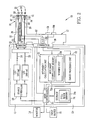
- an endoscope system 10 is constituted of a light source device 11, an electronic endoscope 12, a processor device 13, a monitor 14, and an input device 15 such as a keyboard.
- the light source device 11 produces a plurality of types of illumination light in specific wavelength bands.
- the illumination light from the light source device 11 is applied to the inside of a body cavity, and the electronic endoscope 12 images the light reflected therefrom.
- the processor device 13 produces an endoscopic image from image signals obtained by the electronic endoscope 12. The obtained endoscopic image is displayed on the monitor 14.
- the electronic endoscope 12 is provided with a flexible elongated tube 17, a steering assembly 18, and a head assembly 19 disposed in this order from the side of a control handle unit 16.
- the steering assembly 18 is flexibly bent by a turn of an angle knob 16a provided on the control handle unit 16. By bending the steering assembly 18 in an arbitrary direction and angle, the head assembly 19 is aimed at a desired internal body portion to be examined.
- the flexible elongated tube 17, the steering assembly 18, and the head assembly 19 are collectively called an insert section.
- the endoscope system 10 is switched between a normal mode and a special mode.
- a normal video image is produced in the visible region extending from blue to red.
- a special video image is produced to represent an oxygen saturation level of hemoglobin. The switching is appropriately performed based on input from a mode switch 21 of the electronic endoscope 12 or the input device 15.
- the light source device 11 includes two types of laser sources LD1 and LD2 and a source controller 20.
- the laser source LD1 emits a first laser beam having a center wavelength of 473 nm.
- the first laser beam excites a phosphor 50 provided in the head assembly 19, and produces first white light (pseudo white light).
- the laser source LD2 emits a second laser beam having a center wavelength of 445 nm.
- the second laser beam excites the phosphor 50, and produces second white light (pseudo white light).
- the first laser beam is preferably in a wavelength range of 460 to 480 nm
- the second laser beam is preferably in a wavelength range of 440 to 460 nm.
- the first laser beam emitted from the laser source LD1 is incident upon an optical fiber 24 through a condenser lens (not shown).
- the second laser beam emitted from the laser source LD2 is incident upon an optical fiber 25 through a condenser lens (not shown).
- a broad-area type InGaN laser diode, InGaNAs laser diode, GaNAs laser diode, or the like is available.
- the source controller 20 controls the laser sources LD1 and LD2, and adjusts emission timing of the laser sources LD1 and LD2.
- the laser source LD2 is turned on and the laser source LD1 is turned off in the normal mode.
- the laser sources LD1 and LD2 are alternately turned on and off on a frame-by-frame basis. More specifically, when the laser source LD1 is turned on, the laser source LD2 is turned off. When the laser source LD1 is turned off, the laser source LD2 is turned on.
- a coupler 22 branches the first laser beam from the optical fiber 24 in two beams, and enters the branched two beams into light guides 28 and 29, respectively.
- the coupler 22 also branches the second laser beam from the optical fiber 25 in two beams, and enters the branched two beams into the light guides 28 and 29.
- Each light guide 28, 29 is made of a fiber bundle into which a number of optical fibers are bound.
- the electronic endoscope 12 is provided with a lighting section 33 for applying the two beams transmitted through the light guides 28 and 29 to the internal body portion, and an image pickup section 34 for imaging the internal body portion.
- the electronic endoscope 12 is also provided with a connector 36 that detachably connects the electronic endoscope 12 to the light source device 11 and the processor device 13.
- the lighting section 33 includes two lighting windows 43 and 44 disposed on both right and left sides of the image pickup section 34, and light projection units 47 and 54 disposed in the recess of the lighting windows 43 and 44, respectively. Through the lighting windows 43 and 44, the first or second white light is applied to the internal body portion. Each light projection unit 47, 54 contains the phosphor 50 and a lens 51.
- the image pickup section 34 includes an imaging window 42, which is disposed approximately at the center of the head assembly 19 to receive light reflected from the internal body portion, and an image sensor 60 disposed in the recess of the imaging window 42.
- the phosphor 50 is made of a plurality of types of fluorescent substances (for example, YAG-based fluorescent substance or BAM (BaMgAl 10 O 17 )-based fluorescent substance) that absorb a part of the first laser beam from the laser source LD1 or the second laser beam from the laser source LD2 and emit green to red fluorescence.
- the entrance of the first or second laser beam into the phosphor 50 produces the pseudo white light, by mixing of the green to red fluorescence emitted from the phosphor 50 and the first or second laser beam passed through the phosphor 50 without being absorbed.
- the phosphor 50 preferably has an approximately rectangular parallelepiped shape.
- the phosphor 50 may be formed by compacting the fluorescent substances by a binder into the rectangular parallelepiped shape.
- the mixture of the fluorescent substances and resin such as inorganic glass may be formed into the rectangular parallelepiped shape.
- This phosphor 50 is known under the trademark of Micro White (MW).
- the first white light which is produced by entrance of the first laser beam, has a wavelength of 473 nm being a wavelength band of the first laser beam and wavelengths between 480 nm and 700 nm being a wavelength band of the fluorescence excited by the first laser beam.
- the second white light which is produced by entrance of the second laser beam, has a wavelength of 445 nm being a wavelength band of the second laser beam and wavelengths between 460 nm and 700 nm being a wavelength band of the fluorescence excited by the second laser beam.
- the white light does not necessarily contain each and every wavelength component of the visible light, as long as it contains a plurality of wavelength components of R(red), G(green), and B(blue) being primary colors, such as the pseudo white light described above.
- the white light includes, for example, light having a wavelength component from green to red, light having a wavelength component from blue to green, and the like.
- An objective lens 58 is provided in the recess of the imaging window 42 to capture image light of the internal body portion.
- the image sensor 60 e.g. a CCD (charged coupled device) image sensor or a CMOS (complementary metal-oxide semiconductor) image sensor is provided to perform photoelectric conversion of the image light.
- the image sensor 60 receives the image light from the objective lens 58 at its light receiving surface (imaging surface), and performs the photoelectric conversion of the received image light to output an analog image signal.
- a color CCD is employed as the image sensor 60.
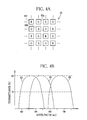
- the image sensor 60 has arrangement patterns of 2- by 2-pixel arranged in both horizontal and vertical directions in its light receiving surface. Each arrangement pattern includes one B pixel 60b having a B (blue) color filter, two G pixels 60g having a G (green) color filter, and one R pixel 60r having a R (red) color filter.
- the B, G, and R color filters have high spectral transmittance in a blue wavelength range, a green wavelength range, and a red wavelength range, as represented by curves 63, 64, and 65 of Fig. 4B , respectively.
- the analog image signal outputted from the image sensor 60 is inputted to an A/D converter 68 through a cable 67.
- the A/D converter 68 converts the image signal into a digital image signal in accordance with its voltage level.
- the converted image signal is inputted to the processor device 13 through the connector 36.
- An imaging controller 70 controls the image sensor 60. As shown in Fig. 5A , in the normal mode, electric charge produced by the second white light (445 nm +fluorescence) is accumulated and read out within one frame period. This accumulation and readout are repeated while the endoscope system 10 stays in the normal mode.
- B1 represents a blue signal outputted from the B pixels of the image sensor 60 in the first frame period.
- G1 represents a green signal outputted from the G pixels, and R1 represents a red signal outputted from the R pixels in the first frame period.
- B2 represents a blue signal outputted from the B pixels in the second frame period.
- G2 represents a green signal outputted from the G pixels, and R2 represents a red signal outputted from the R pixels in the second frame period.
- the processor device 13 is constituted of a main controller 71, a movement calculation unit 72, an image processing unit 73, and storage 74.
- the main controller 71 is connected to the monitor 14 and the input device 15.
- the main controller 71 controls the operation of the image processing unit 73, the source controller 20 of the light source device 11, the imaging controller 70 of the electronic endoscope 12, and the monitor 14 based on input from the mode switch 21 of the electronic endoscope 12 and the input device 15.
- the movement calculation unit 72 calculates a signal ratio R2/R1 between the red signal R1 of a first frame image obtained in the first frame period and the red signal R2 of a second frame image obtained in the second frame period. Then, the movement calculation unit 72 calculates from the signal ratio R2/R1 a movement M, which represents in numerical form various movements including a shake of the head assembly 19 and a body motion of the internal body portion.
- the correlation between the movement M and the signal ratio R2/R1 is stored in a movement correlation memory 72a.
- a warning unit 72b puts in the special video image a warning sign "!!", which indicates "there is a possibility of the occurrence of artifact".
- the movement M calculated by the movement calculation unit 72 is sent to the image processing unit 73.
- the artifact can occur not only by the movements but also by variation in the intensity ratio between the first and second white light caused by exposure control. For this reason, the intensity ratio between the first and second white light is preferably kept constant.
- the reason why the movement M is calculated from the signal ratio R2/R1, as described above, is as follows.
- the first white light emitted in the first frame period and the second white light emitted in the second frame period have approximately the same spectral distribution in the red wavelength range (see Fig. 3 ).
- the signal ratio R2/R1 between the red signals R2 and R1 stays at an almost constant value C, which depends on the intensity ratio between the first and second white light.
- the signal ratio R2/R1 deviates from the constant value C in accordance with the amount of the movement. For this reason, the movement M is obtainable by calculating a deviation of the signal ratio R2/R1 from the constant value C.
- the warning unit 72b puts in the special video image a warning sign for indicating that there is a possibility of the occurrence of an error in calculation of the oxygen saturation level.
- a warning sign "HIGH StO 2 14b is put in the special video image to indicate that "a calculated oxygen saturation level is possibly higher than an actual value”.
- the signal ratio R2/R1 is smaller than the predetermined range S, as shown in Fig.
- a warning sign "LOW StO 2 " 14c is put in the special video image to indicate that "a calculated oxygen saturation level is possibly lower than an actual value". Note that, the warning signs about the oxygen saturation level and the artifact may be displayed at the same time on the monitor 14.
- the reason why the error in calculation of the oxygen saturation level varies depending on the signal ratio R2/R1 is as follows.
- the size of an object becomes larger in the second frame image than that in the first frame image due to optical properties of the objective lens 58.
- the distance between the head assembly 19 and the object is shorter in the second frame image, so the amount of light exposure is larger in the second frame image than that in the first frame image.
- the signal ratio R2/R1 becomes larger than the predetermined range S, the oxygen saturation level (correlates with B1/G2) tends to be larger than the actual value.
- the distance between the head assembly 19 and the object is shorter in the first frame image, so the amount of light exposure is larger in the first frame image than that in the second frame image.
- the signal ratio R2/R1 becomes smaller than the predetermined range S, so the oxygen saturation level tends to be smaller than the actual value.
- the image processing unit 73 includes a normal video image processor 80, a special video image processor 81, and a still image processor 82.
- the image processing unit 73 applies predetermined image processing to the image signal from the electronic endoscope 12.
- the normal video image processor 80 applies the predetermined image processing to the image signal obtained in the normal mode to produce a normal video image.
- the special video image processor 81 calculates the oxygen saturation level of blood based on the image signal obtained in the special mode, and produces a special video image (oxygen saturation video image) in which the normal video image is artificially colored.
- the special video image processor 81 includes a signal ratio calculator 84, a correlation memory 85, an oxygen saturation level calculator 86, and a video image generator 88.
- the signal ratio calculator 84 calculates a signal ratio B1/G2 between the blue signal B1 of the first frame image and the green signal G2 of the second frame image, and a signal ratio R2/G2 between the red signal R2 of the second frame image and the green signal G2 of the second frame image.
- the signal ratio calculator 84 calculates the signal ratios with respect to the pixel situated in the same position.
- the signal ratios may be calculated with respect to each and every pixel, or only in pixels situated within a blood vessel area. In this case, the blood vessel area is determined based on difference in the image signal between the blood vessel area and the other area.
- the correlation memory 85 stores the correlation among the signal ratios B1/G2 and R2/G2 and the oxygen saturation level. As shown in Fig. 8 , this correlation takes the form of a two-dimensional table in which contour lines representing the oxygen saturation level are defined in two-dimensional space. The position and shape of the contour lines are obtained by physical simulation of light scattering, and are variable in accordance with blood volume. For example, variation in the blood volume widens or narrows distance between the contour lines. Note that, the signal ratios B1/G2 and R2/G2 are depicted in log scale.
- a line 90 represents a light absorption coefficient of the oxygenated hemoglobin
- a line 91 represents a light absorption coefficient of the deoxygenated hemoglobin.
- the use of a wavelength of, for example, 473 nm at which the light absorption coefficient much differs between the oxygenated hemoglobin and the deoxygenated hemoglobin allows the obtainment of the oxygen saturation level.
- the blue signal B1 that corresponds to the light of 473 nm is highly dependent not only on the oxygen saturation level but also on the blood volume.
- the use of the signal ratios B1/G2 and R2/G2, which are obtained from the red signal R2 that is mainly dependent on the blood volume and the green signal G2 being a reference signal (standardization signal) of the blue signal B1 and the red signal R2, in addition to the blue signal B1, allows the obtainment of the oxygen saturation level with high accuracy while eliminating the influence of the blood volume.
- the correlation memory 85 also stores the correlation between the signal ratio R2/G2 and the blood volume as shown in Fig. 10 .
- This correlation takes the form of a one-dimensional table in which the blood volume is increased with increase in the signal ratio R2/G2.
- the correlation between the signal ratio R2/G2 and the blood volume is used in calculation of the blood volume.
- a signal value of the signal ratio B1/G2 increases with increase in the signal ratio R2/G2, in other words, why the contour line representing the oxygen saturation level of 0% ascends slantly, as shown in Fig. 8 , is as follows.
- the blood volume increases with increase in the signal ratio R2/G2, because of the correlation between the signal ratio R2/G2 and the blood volume.
- a signal value of the green signal G2 decreases most greatly with increase in the blood volume, and a signal value of the blue signal B1 decreases next greatly.
- the signal value of the green signal G2 decreases more greatly than the signal value of the blue signal B1 with increase in the blood volume. In other words, the signal ratio B1/G2 increases with increase in the blood volume.
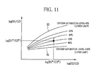
- the oxygen saturation level calculator 86 calculates the oxygen saturation level of each pixel with the use of the correlations stored in the correlation memory 85 and the signal ratios B1/G2 and R2/G2 obtained by the signal ratio calculator 84. As shown in Fig. 11 , a point P that corresponds to the signal ratios B1*/G2* and R2*/G2* obtained by the signal ratio calculator 84 is determined in the correlation stored in the correlation memory 85. When the point P is situated between a lower limit line 93 representing an oxygen saturation level of 0% and an upper limit line 94 representing an oxygen saturation level of 100%, the point P indicates the percentile of the oxygen saturation level. Taking Fig. 11 as an example, the point P is situated in a contour line of 60%, so the oxygen saturation level is 60%.
- the oxygen saturation level is determined to be 0%.
- the oxygen saturation level is determined to be 100%. Note that, in a case where the point is out of the range between the lower limit line 93 and the upper limit line 94, the oxygen saturation level of the pixel is judged to be unreliable and may not be displayed on the monitor 14.
- the video image generator 88 produces the special video image (oxygen saturation video image) based on the oxygen saturation level obtained by the oxygen saturation level calculator 86.
- the produced special video image is displayed on the monitor 14.
- the entire normal video image may be artificially colored with specific colors in accordance with the degree of the oxygen saturation level.
- only a hypoxic area, which has the oxygen saturation level lower than a predetermined value, may be artificially colored, while the other areas may be displayed with normal colors (colors used in the normal video image).
- the still image processor 82 carries out freeze processing in which a video frame is stored in a still image memory 74a as a still image at the moment of pressing a freeze button 16b provided in the electronic endoscope 12. In the normal mode, out of the normal video image, one or more video frames are stored as normal still images in the still image memory 74a by the freeze processing.
- the freeze processing is carried out only when a movement judging unit 82a judges that the movement M is a threshold value or less.
- the freeze processing out of video frames composing the special video image, one or more video frames are stored as special still images in the still image memory 74a. Only the video frames captured at the moment when the movement M is equal to or less than the threshold value are stored, as described above, so it is possible to store only the images that have no or little deviation. Note that, in a case where even if the freeze button 16a is pressed, no freeze processing is carried out because of the large movement M, the monitor 14 may display as such.
- the operation of the present invention will be described with referring to a flowchart of Fig. 12 .
- the endoscope system 10 is switched to the special mode by operation of the mode switch 21 provided in the electronic endoscope 12, the first white light is applied to the internal body portion.
- the image sensor 60 captures the reflected first white light to obtain the image signal of the first frame period.
- the first frame image including the blue signal B1, the green signal G1, and the red signal R1 is obtained.
- the second white light is applied to the internal body portion.
- the image sensor 60 captures the reflected second white light to obtain the image signal of the second frame period.
- the second frame image including the blue signal B2, the green signal G2, and the red signal R2 is obtained.
- the signal ratio calculator 84 calculates the signal ratios B1/G2 and R2/G2 of each and every pixel.
- the oxygen saturation level calculator 86 calculates the oxygen saturation level of each pixel, based on the correlation stored in the correlation memory 85 and the signal ratios B1/G2 and R2/G2.
- the special image is produced based on the calculated oxygen saturation level. By displaying the produced special images in a sequential manner, the special video image is displayed on the monitor 14.
- the signal ratio R2/R1 between the red signal R1 of the first frame image and the red signal R2 of the second frame image is calculated.
- the warning sign "!!" which indicates "there is a possibility of the occurrence of artifact"
- the warning sign "HIGH StO 2 is put in the special video image to indicate that "a calculated oxygen saturation level is possibly higher than an actual value”.
- the special video image may be displayed in monochrome in a case where the movement M is more than the threshold value or out of the predetermined range, while the special video image may be displayed in color in a case where the movement M is the threshold value or less or within the predetermined range.
- the phosphor 50 is provided in the head assembly 19, but may be provided in the light source device 11. In this case, the phosphor 50 is disposed between the laser source LD1 (473 nm) and the optical fiber 24 and between the laser source LD2 (445 nm) and the optical fiber 25.
- the oxygen saturation video image is used as an example of the special video image.
- the present invention is applicable to any image (NBI image and the like) that is composed of a plurality of frame images obtained by a sequential method, including a frame sequential method and a line sequential method.
- the warning sign is put in the special video image, but another type of information such as text may be used as warning information.
- text of "there is a possibility of the occurrence of artifact" may be displayed in the video image.
- a lamp provided on the monitor may be turned on, instead of displaying the warning sign or text in the video image.
- oxygen saturation level is imaged in this embodiment.
- an oxygenated hemoglobin index calculated by "blood volume (the sum of oxygenated hemoglobin and deoxygenated hemoglobin) x oxygen saturation level (%)” or a deoxygenated hemoglobin index calculated by "blood volume x (100 - oxygen saturation level) (%)” may be imaged instead of or in addition to the oxygen saturation level.
Landscapes
- Health & Medical Sciences (AREA)
- Life Sciences & Earth Sciences (AREA)
- Surgery (AREA)
- Physics & Mathematics (AREA)
- Engineering & Computer Science (AREA)
- Biophysics (AREA)
- Veterinary Medicine (AREA)
- Public Health (AREA)
- Pathology (AREA)
- General Health & Medical Sciences (AREA)
- Animal Behavior & Ethology (AREA)
- Biomedical Technology (AREA)
- Heart & Thoracic Surgery (AREA)
- Medical Informatics (AREA)
- Molecular Biology (AREA)
- Optics & Photonics (AREA)
- Radiology & Medical Imaging (AREA)
- Nuclear Medicine, Radiotherapy & Molecular Imaging (AREA)
- Signal Processing (AREA)
- Spectroscopy & Molecular Physics (AREA)
- Endoscopes (AREA)
- Instruments For Viewing The Inside Of Hollow Bodies (AREA)
Claims (13)
- Endoskopsystem (10), umfassend:eine Beleuchtungseinrichtung (33) zum sequentiellen Aufbringen mehrerer Typen von Beleuchtungslicht unterschiedlicher Wellenlängenbänder auf einen internen Körperteil;eine Bildaufnahmeeinrichtung (34) zum sequentiellen Aufnehmen reflektierten Lichts von dem internen Körperteil, um mehrere Einzelbilder von Bildsignalen entsprechend den Typen von Beleuchtungslicht zu gewinnen;eine Videobild-Erzeugungseinrichtung (88) zum Erzeugen eines endoskopischen Bilds eines Videoeinzelbilds basierend auf den mehreren Einzelbildern von Bildsignalen, und zum sequentiellen Ausgeben mehrerer erzeugter endoskopischer Bilder, um ein endoskopisches Videobild zu erzeugen; undeine Monitoreinrichtung (14) zum Anzeigen des endoskopischen Videobilds;gekennzeichnet durcheine Warneinrichtung (72b) zum Ausgeben einer Warnung, wenn ein Signalverhältnis zwischen mindestens zwei der Bildsignale aus einem vorbestimmten Bereich herausfällt.
- Endoskopsystem (10) nach Anspruch 1, bei dem die Beleuchtungseinrichtung (33) erstes Beleuchtungslicht in einer ersten Einzelbildperiode und zweites Beleuchtungslicht in einer zweiten Einzelbildperiode emittiert, wobei das erste und das zweite Beleuchtungslicht die gleiche Spektralverteilung in einem spezifischen Wellenlängenbereich aufweisen;
die Bildaufnahmeeinrichtung (34) ein erstes Bildsignal in einer ersten Einzelbildperiode und ein zweites Bildsignal in der zweiten Einzelbildperiode mit Hilfe eines Farbbildsensors (60) gewinnt, der ein spezielles Pixel mit einem Farbfilter zum Durchlassen von Licht in dem spezifischen Wellenlängenbereich aufweist; und
wenn ein Signalverhältnis zwischen einer ersten Signalkomponente des ersten Bildsignals und einer zweiten Signalkomponente des zweiten Bildsignals außerhalb eines vorbestimmten Bereichs liegt, die Warneinrichtung (72b) die Warnung ausgibt,
wobei die erste Signalkomponente sich auf eine Komponente in dem ersten, von dem speziellen Pixel ausgegebenen Bildsignal bezieht, und die zweite Signalkomponente sich auf eine Komponente des zweiten, von dem speziellen Pixel ausgegebenen Bildsignal bezieht. - Endoskopsystem (10) nach Anspruch 2, bei dem das erste Beleuchtungslicht erstes blaues Licht in einem schmalen Wellenlängenband und erstes grünes bis rotes Licht in einem breiten Wellenlängenband enthält, wobei das erste grüne bis rote Licht erhalten wird durch eine Wellenlängenumwandlung des ersten blauen Lichts mit Hilfe eines Wellenlängen-Wandlerelements (50);
das zweite Beleuchtungslicht zweites blaues Licht in einem schmalen Wellenlängenband und zweites grünes bis rotes Licht in einem breiten Wellenlängenband enthält, und das zweite grüne bis rote Licht erhalten wird durch eine Wellenlängenumwandlung des zweiten blauen Lichts mit Hilfe eines WellenlängenUmwandlungselements (50), und eine Wellenlänge des ersten blauen Lichts verschieden ist von einer Wellenlänge des zweiten blauen Lichts; und
das erste und das zweite Beleuchtungslicht die gleiche Spektralverteilung in einem roten Wellenlängenbereich aufweisen. - Endoskopsystem (10) nach Anspruch 3, bei dem das erste und das zweite blaue Licht von Halbleiterlichtquellen emittiert wird.
- Endoskopsystem (10) nach einem der Ansprüche 1 bis 4, bei dem, wenn das Signalverhältnis aus einem ersten numerischen Bereich herausfällt, die Warneinrichtung (72b) eine erste Warnung über eine Körperbewegung des inneren Körperteils oder ein Wackeln eines Bildsensors (60) ausgibt.
- Endoskopsystem (10) nach einem der Ansprüche 1 bis 5, bei dem
das endoskopische Videobild ein Sauerstoffsättigungs-Videobild ist, welches einen Sauerstoff-Sättigungspegel des Bluts abbildet; und
wenn das Signalverhältnis aus einem zweiten numerischen Bereich herausfällt, die Warneinrichtung (72) eine zweite Warnung über den Sauerstoffsättigungspegel ausgibt. - Endoskopsystem (10) nach einem der Ansprüche 1 bis 6, bei dem die Warneinrichtung (72b) eine Warnung dadurch ausgibt, dass sie die Art der Anzeige des endoskopischen Videobilds auf der Monitoreinrichtung (14) ändert.
- Endoskopsystem (10) nach einem der Ansprüche 1 bis 6, bei dem die Warneinrichtung (72b) die Warnung dadurch ausgibt, dass sie ein Warnzeichen (14a, 14b, 14c) auf der Monitoreinrichtung (14) anzeigt.
- Endoskopsystem (10) nach Anspruch 8, bei dem das Warnzeichen (14a, 14b, 14c) auf der Monitoreinrichtung (14) zusammen mit dem endoskopischen Videobild angezeigt wird.
- Endoskopsystem (10) nach einem der Ansprüche 1 bis 9, weiterhin umfassend eine Stehbild-Aufzeichnungseinrichtung (71) zum Speichern eines oder mehrerer Videoeinzelbilder der endoskopischen Bilder in Form von Stehbildern in einer Stehbild-Speichereinrichtung (74a), wenn das Signalverhältnis sich innerhalb des vorbestimmten Bereichs befindet.
- Prozessoreinrichtung (13) eines Endoskopsystems (10), an die ein elektronisches Endoskop (12) und eine Monitoreinrichtung (14) angeschlossen sind, wobei das elektronische Endoskop (12) eine Beleuchtungseinrichtung (33) zum sequentiellen Aufbringen mehrerer Typen von Beleuchtungslicht unterschiedlicher Wellenlängenbänder auf einen inneren Körperteil enthält, ferner eine Bildaufnahmeeinrichtung (34) zum sequentiellen Aufnehmen reflektierten Lichts von dem inneren Körperteil, um mehrere Einzelbilder von Bildsignalen zu gewinnen, die den Typen an Beleuchtungslicht entsprechen, und eine Monitoreinrichtung (14) enthält, wobei die Prozessoreinrichtung (13) umfasst:eine Videobild-Erzeugungseinrichtung (88) zum Erzeugen eines endoskopischen Bilds eines Videoeinzelbilds basierend auf den mehreren Einzelbildern von Bildsignalen, und zum sequentiellen Ausgeben mehrerer der erzeugten endoskopischen Bilder an die Monitoreinrichtung (14), um ein endoskopisches Videobild zu erzeugen;gekennzeichnet durcheine Warneinrichtung (72b) zum Ausgeben einer Warnung, wenn ein Signalverhältnis zwischen mindestens zwei der Bildsignale aus einem vorbestimmten Bereich herausfällt.
- Verfahren zum Anzeigen eines endoskopischen Videobilds, umfassend folgende Schritte:sequentielles Aufbringen mehrerer Typen von Beleuchtungslicht unterschiedlicher Wellenlängenbänder auf einen inneren Körperteil;sequentielles Aufnehmen reflektierten Lichts von dem inneren Körperteil, um mehrere Einzelbilder von Bildsignalen zu erhalten, die den Typen von Beleuchtungslicht entsprechen;Erzeugen eines endoskopischen Bilds eines Videoeinzelbilds basierend auf den mehreren Einzelbildern von Bildsignalen; undsequentielles Anzeigen auf einer Monitoreinrichtung (14) als endoskopisches Videobild von mehreren der endoskopischen Bilder, die durch Wiederholen des Aufbring-Schritts, des Aufnahmeschritts und des Erzeugungsschritts erzeugt wurden;gekennzeichnet durch den Schritt:Vergleichen eines Signalverhältnisses zwischen mindestens zwei der Bildsignale mit einem vorbestimmten Bereich; undAusgeben einer Warnung, wenn das Signalverhältnis aus dem vorbestimmten Bereich herausfällt.
- Verfahren nach Anspruch 12, bei dem die Warnung (14a, 14b, 14c) auf der Monitoreinrichtung (14) zusammen mit dem endoskopischen Videobild angezeigt wird.
Applications Claiming Priority (1)
| Application Number | Priority Date | Filing Date | Title |
|---|---|---|---|
| JP2012054503A JP5568584B2 (ja) | 2012-03-12 | 2012-03-12 | 内視鏡システム、内視鏡システムのプロセッサ装置、及び内視鏡システムの作動方法 |
Publications (2)
| Publication Number | Publication Date |
|---|---|
| EP2638842A1 EP2638842A1 (de) | 2013-09-18 |
| EP2638842B1 true EP2638842B1 (de) | 2015-04-22 |
Family
ID=47900510
Family Applications (1)
| Application Number | Title | Priority Date | Filing Date |
|---|---|---|---|
| EP20130155255 Active EP2638842B1 (de) | 2012-03-12 | 2013-02-14 | Elektronisches Endoskopsystem, elektronischer Endoskopprozessor und Verfahren zur darstellung videoendoskopischer Bilddaten |
Country Status (4)
| Country | Link |
|---|---|
| US (1) | US9084529B2 (de) |
| EP (1) | EP2638842B1 (de) |
| JP (1) | JP5568584B2 (de) |
| CN (1) | CN103300810B (de) |
Families Citing this family (21)
| Publication number | Priority date | Publication date | Assignee | Title |
|---|---|---|---|---|
| JP5977772B2 (ja) * | 2014-02-06 | 2016-08-24 | 富士フイルム株式会社 | 内視鏡システム、内視鏡システムのプロセッサ装置、内視鏡システムの作動方法、プロセッサ装置の作動方法 |
| WO2015131026A1 (en) | 2014-02-27 | 2015-09-03 | Intuitive Surgical Operations, Inc. | System and method for specular reflection detection and reduction |
| JP5992936B2 (ja) * | 2014-02-27 | 2016-09-14 | 富士フイルム株式会社 | 内視鏡システム、内視鏡システム用プロセッサ装置、内視鏡システムの作動方法、内視鏡システム用プロセッサ装置の作動方法 |
| JP6010571B2 (ja) * | 2014-02-27 | 2016-10-19 | 富士フイルム株式会社 | 内視鏡システム、内視鏡システム用プロセッサ装置、内視鏡システムの作動方法、内視鏡システム用プロセッサ装置の作動方法 |
| JP6151850B2 (ja) * | 2014-03-28 | 2017-06-21 | 富士フイルム株式会社 | 内視鏡システム、内視鏡システムのプロセッサ装置、及び内視鏡システムの作動方法 |
| JP6150364B2 (ja) * | 2014-03-28 | 2017-06-21 | 富士フイルム株式会社 | 内視鏡システム、内視鏡システムのプロセッサ装置、及び内視鏡システムの作動方法 |
| EP3127466B1 (de) * | 2014-03-31 | 2018-08-22 | Fujifilm Corporation | Endoskopsystem, verarbeitungsvorrichtung des endoskopsystems und verfahren zum betrieb des endoskopsystems |
| JP6276149B2 (ja) * | 2014-09-12 | 2018-02-07 | 富士フイルム株式会社 | 内視鏡システム及びその作動方法 |
| JP6243311B2 (ja) * | 2014-09-30 | 2017-12-06 | 富士フイルム株式会社 | 内視鏡用のプロセッサ装置、内視鏡用のプロセッサ装置の作動方法、内視鏡用の制御プログラム |
| JP6195328B2 (ja) * | 2015-09-24 | 2017-09-13 | Hoya株式会社 | 分析装置 |
| JP6448509B2 (ja) | 2015-10-30 | 2019-01-09 | 富士フイルム株式会社 | 内視鏡システム、プロセッサ装置、及び、内視鏡システムの作動方法 |
| JP6272956B2 (ja) * | 2016-07-21 | 2018-01-31 | 富士フイルム株式会社 | 内視鏡システム、内視鏡システムのプロセッサ装置、内視鏡システムの作動方法、プロセッサ装置の作動方法 |
| JP6570490B2 (ja) * | 2016-08-18 | 2019-09-04 | 富士フイルム株式会社 | 内視鏡システム及び内視鏡システムの作動方法 |
| JP6654117B2 (ja) * | 2016-08-31 | 2020-02-26 | 富士フイルム株式会社 | 内視鏡システム及び内視鏡システムの作動方法 |
| KR102669621B1 (ko) * | 2016-12-20 | 2024-05-28 | 한국전기연구원 | 지능형 고해상도 내시경 영상을 획득하여 저장하는 영상 제공 방법 및 장치 |
| US11039795B2 (en) | 2017-06-28 | 2021-06-22 | Welch Allyn, Inc. | Physiological monitoring and related methods |
| JP6891304B2 (ja) * | 2018-02-09 | 2021-06-18 | 富士フイルム株式会社 | 内視鏡システム |
| RU194603U1 (ru) * | 2019-09-30 | 2019-12-17 | Общество с ограниченной ответственностью «Модуль» | Устройство управления видеоэндоскопом для осмотра фитингов контейнеров и фитинговых упоров железнодорожных платформ |
| WO2021122536A1 (en) | 2019-12-19 | 2021-06-24 | Ambu A/S | Image capture selection |
| CN112231183B (zh) * | 2020-07-13 | 2022-09-30 | 国网宁夏电力有限公司电力科学研究院 | 通信设备告警预测方法和装置、电子设备和可读存储介质 |
| US20240000293A1 (en) * | 2020-11-09 | 2024-01-04 | Ariel Scientific Innovations Ltd. | Medical imaging method and device |
Family Cites Families (11)
| Publication number | Priority date | Publication date | Assignee | Title |
|---|---|---|---|---|
| JPH0620318B2 (ja) * | 1984-09-14 | 1994-03-16 | オリンパス光学工業株式会社 | 内視鏡装置 |
| JP2965161B2 (ja) * | 1989-02-28 | 1999-10-18 | オリンパス光学工業株式会社 | 内視鏡撮像装置 |
| TW387560U (en) * | 1994-05-13 | 2000-04-11 | Prec Optics Coroporation | Viewing scope with image intensification |
| JPH0868952A (ja) | 1994-08-31 | 1996-03-12 | Asahi Optical Co Ltd | 電子内視鏡装置 |
| JP2001037718A (ja) * | 1999-05-26 | 2001-02-13 | Olympus Optical Co Ltd | 画像診断装置及び内視鏡装置 |
| JP5570769B2 (ja) * | 2009-07-23 | 2014-08-13 | オリンパス株式会社 | 内視鏡装置、計測方法、およびプログラム |
| JP5452300B2 (ja) * | 2010-03-19 | 2014-03-26 | 富士フイルム株式会社 | 電子内視鏡システム、電子内視鏡用のプロセッサ装置、電子内視鏡システムの作動方法、病理観察装置および病理顕微鏡装置 |
| JP2011234844A (ja) * | 2010-05-10 | 2011-11-24 | Olympus Corp | 制御装置、内視鏡装置及びプログラム |
| JP5460488B2 (ja) * | 2010-06-29 | 2014-04-02 | 富士フイルム株式会社 | 電子内視鏡システム、電子内視鏡用のプロセッサ装置、画像検索システム、及び電子内視鏡システムの作動方法 |
| JP5167440B2 (ja) * | 2011-04-11 | 2013-03-21 | オリンパスメディカルシステムズ株式会社 | 内視鏡装置 |
| JP2013099464A (ja) * | 2011-11-09 | 2013-05-23 | Fujifilm Corp | 内視鏡システム、内視鏡システムのプロセッサ装置、及び画像表示方法 |
-
2012
- 2012-03-12 JP JP2012054503A patent/JP5568584B2/ja active Active
-
2013
- 2013-02-08 US US13/762,429 patent/US9084529B2/en active Active
- 2013-02-14 EP EP20130155255 patent/EP2638842B1/de active Active
- 2013-02-27 CN CN201310061465.3A patent/CN103300810B/zh active Active
Also Published As
| Publication number | Publication date |
|---|---|
| JP5568584B2 (ja) | 2014-08-06 |
| JP2013188244A (ja) | 2013-09-26 |
| US20130235177A1 (en) | 2013-09-12 |
| EP2638842A1 (de) | 2013-09-18 |
| CN103300810B (zh) | 2016-05-04 |
| US9084529B2 (en) | 2015-07-21 |
| CN103300810A (zh) | 2013-09-18 |
Similar Documents
| Publication | Publication Date | Title |
|---|---|---|
| EP2638842B1 (de) | Elektronisches Endoskopsystem, elektronischer Endoskopprozessor und Verfahren zur darstellung videoendoskopischer Bilddaten | |
| US9345392B2 (en) | Endoscope system and method for imaging exposure control | |
| US9167960B2 (en) | Endoscope system, processor device thereof, and image producing method | |
| US20130245411A1 (en) | Endoscope system, processor device thereof, and exposure control method | |
| US9801573B2 (en) | Endoscope system, processor device, and method for operating endoscope system | |
| EP2526854B1 (de) | Endoskopsystem und Verfahren zur Unterstützung bei der diagnostischen Endoskopie | |
| US10045719B2 (en) | Endoscope system, processor device thereof, and method for displaying oxygen saturation level | |
| EP2476373B1 (de) | Endoskopsystem und Prozessorvorrichtung dafür | |
| US10257429B2 (en) | Rolling shutter imaging device and endoscope apparatus including the same | |
| US9918613B2 (en) | Endoscope system and operating method thereof | |
| EP2468187B1 (de) | Endoskopsystem und Prozessorvorrichtung damit und Verfahren zur Erzeugung von Bildern | |
| US20140031628A1 (en) | Endoscope system, processor device of endoscope system, and method for controlling display of endoscope image | |
| US9565399B2 (en) | Endoscope system, processor device thereof, and image processing method |
Legal Events
| Date | Code | Title | Description |
|---|---|---|---|
| PUAI | Public reference made under article 153(3) epc to a published international application that has entered the european phase |
Free format text: ORIGINAL CODE: 0009012 |
|
| AK | Designated contracting states |
Kind code of ref document: A1 Designated state(s): AL AT BE BG CH CY CZ DE DK EE ES FI FR GB GR HR HU IE IS IT LI LT LU LV MC MK MT NL NO PL PT RO RS SE SI SK SM TR |
|
| AX | Request for extension of the european patent |
Extension state: BA ME |
|
| 17P | Request for examination filed |
Effective date: 20140218 |
|
| RBV | Designated contracting states (corrected) |
Designated state(s): AL AT BE BG CH CY CZ DE DK EE ES FI FR GB GR HR HU IE IS IT LI LT LU LV MC MK MT NL NO PL PT RO RS SE SI SK SM TR |
|
| GRAP | Despatch of communication of intention to grant a patent |
Free format text: ORIGINAL CODE: EPIDOSNIGR1 |
|
| RIC1 | Information provided on ipc code assigned before grant |
Ipc: A61B 1/06 20060101ALI20141027BHEP Ipc: A61B 1/00 20060101AFI20141027BHEP Ipc: A61B 1/045 20060101ALI20141027BHEP Ipc: A61B 5/1455 20060101ALI20141027BHEP Ipc: A61B 5/00 20060101ALI20141027BHEP |
|
| INTG | Intention to grant announced |
Effective date: 20141112 |
|
| RAP1 | Party data changed (applicant data changed or rights of an application transferred) |
Owner name: FUJIFILM CORPORATION |
|
| GRAS | Grant fee paid |
Free format text: ORIGINAL CODE: EPIDOSNIGR3 |
|
| GRAA | (expected) grant |
Free format text: ORIGINAL CODE: 0009210 |
|
| AK | Designated contracting states |
Kind code of ref document: B1 Designated state(s): AL AT BE BG CH CY CZ DE DK EE ES FI FR GB GR HR HU IE IS IT LI LT LU LV MC MK MT NL NO PL PT RO RS SE SI SK SM TR |
|
| REG | Reference to a national code |
Ref country code: GB Ref legal event code: FG4D |
|
| REG | Reference to a national code |
Ref country code: CH Ref legal event code: EP |
|
| REG | Reference to a national code |
Ref country code: AT Ref legal event code: REF Ref document number: 722682 Country of ref document: AT Kind code of ref document: T Effective date: 20150515 |
|
| REG | Reference to a national code |
Ref country code: IE Ref legal event code: FG4D |
|
| REG | Reference to a national code |
Ref country code: DE Ref legal event code: R096 Ref document number: 602013001536 Country of ref document: DE Effective date: 20150603 |
|
| REG | Reference to a national code |
Ref country code: NL Ref legal event code: VDEP Effective date: 20150422 |
|
| REG | Reference to a national code |
Ref country code: AT Ref legal event code: MK05 Ref document number: 722682 Country of ref document: AT Kind code of ref document: T Effective date: 20150422 |
|
| REG | Reference to a national code |
Ref country code: LT Ref legal event code: MG4D |
|
| PG25 | Lapsed in a contracting state [announced via postgrant information from national office to epo] |
Ref country code: NL Free format text: LAPSE BECAUSE OF FAILURE TO SUBMIT A TRANSLATION OF THE DESCRIPTION OR TO PAY THE FEE WITHIN THE PRESCRIBED TIME-LIMIT Effective date: 20150422 |
|
| PG25 | Lapsed in a contracting state [announced via postgrant information from national office to epo] |
Ref country code: NO Free format text: LAPSE BECAUSE OF FAILURE TO SUBMIT A TRANSLATION OF THE DESCRIPTION OR TO PAY THE FEE WITHIN THE PRESCRIBED TIME-LIMIT Effective date: 20150722 Ref country code: FI Free format text: LAPSE BECAUSE OF FAILURE TO SUBMIT A TRANSLATION OF THE DESCRIPTION OR TO PAY THE FEE WITHIN THE PRESCRIBED TIME-LIMIT Effective date: 20150422 Ref country code: ES Free format text: LAPSE BECAUSE OF FAILURE TO SUBMIT A TRANSLATION OF THE DESCRIPTION OR TO PAY THE FEE WITHIN THE PRESCRIBED TIME-LIMIT Effective date: 20150422 Ref country code: PT Free format text: LAPSE BECAUSE OF FAILURE TO SUBMIT A TRANSLATION OF THE DESCRIPTION OR TO PAY THE FEE WITHIN THE PRESCRIBED TIME-LIMIT Effective date: 20150824 Ref country code: HR Free format text: LAPSE BECAUSE OF FAILURE TO SUBMIT A TRANSLATION OF THE DESCRIPTION OR TO PAY THE FEE WITHIN THE PRESCRIBED TIME-LIMIT Effective date: 20150422 Ref country code: LT Free format text: LAPSE BECAUSE OF FAILURE TO SUBMIT A TRANSLATION OF THE DESCRIPTION OR TO PAY THE FEE WITHIN THE PRESCRIBED TIME-LIMIT Effective date: 20150422 |
|
| PG25 | Lapsed in a contracting state [announced via postgrant information from national office to epo] |
Ref country code: IS Free format text: LAPSE BECAUSE OF FAILURE TO SUBMIT A TRANSLATION OF THE DESCRIPTION OR TO PAY THE FEE WITHIN THE PRESCRIBED TIME-LIMIT Effective date: 20150822 Ref country code: RS Free format text: LAPSE BECAUSE OF FAILURE TO SUBMIT A TRANSLATION OF THE DESCRIPTION OR TO PAY THE FEE WITHIN THE PRESCRIBED TIME-LIMIT Effective date: 20150422 Ref country code: GR Free format text: LAPSE BECAUSE OF FAILURE TO SUBMIT A TRANSLATION OF THE DESCRIPTION OR TO PAY THE FEE WITHIN THE PRESCRIBED TIME-LIMIT Effective date: 20150723 Ref country code: AT Free format text: LAPSE BECAUSE OF FAILURE TO SUBMIT A TRANSLATION OF THE DESCRIPTION OR TO PAY THE FEE WITHIN THE PRESCRIBED TIME-LIMIT Effective date: 20150422 Ref country code: LV Free format text: LAPSE BECAUSE OF FAILURE TO SUBMIT A TRANSLATION OF THE DESCRIPTION OR TO PAY THE FEE WITHIN THE PRESCRIBED TIME-LIMIT Effective date: 20150422 |
|
| REG | Reference to a national code |
Ref country code: FR Ref legal event code: PLFP Year of fee payment: 4 |
|
| REG | Reference to a national code |
Ref country code: DE Ref legal event code: R097 Ref document number: 602013001536 Country of ref document: DE |
|
| PG25 | Lapsed in a contracting state [announced via postgrant information from national office to epo] |
Ref country code: DK Free format text: LAPSE BECAUSE OF FAILURE TO SUBMIT A TRANSLATION OF THE DESCRIPTION OR TO PAY THE FEE WITHIN THE PRESCRIBED TIME-LIMIT Effective date: 20150422 Ref country code: EE Free format text: LAPSE BECAUSE OF FAILURE TO SUBMIT A TRANSLATION OF THE DESCRIPTION OR TO PAY THE FEE WITHIN THE PRESCRIBED TIME-LIMIT Effective date: 20150422 |
|
| PLBE | No opposition filed within time limit |
Free format text: ORIGINAL CODE: 0009261 |
|
| STAA | Information on the status of an ep patent application or granted ep patent |
Free format text: STATUS: NO OPPOSITION FILED WITHIN TIME LIMIT |
|
| PG25 | Lapsed in a contracting state [announced via postgrant information from national office to epo] |
Ref country code: RO Free format text: LAPSE BECAUSE OF NON-PAYMENT OF DUE FEES Effective date: 20150422 Ref country code: CZ Free format text: LAPSE BECAUSE OF FAILURE TO SUBMIT A TRANSLATION OF THE DESCRIPTION OR TO PAY THE FEE WITHIN THE PRESCRIBED TIME-LIMIT Effective date: 20150422 Ref country code: PL Free format text: LAPSE BECAUSE OF FAILURE TO SUBMIT A TRANSLATION OF THE DESCRIPTION OR TO PAY THE FEE WITHIN THE PRESCRIBED TIME-LIMIT Effective date: 20150422 Ref country code: SK Free format text: LAPSE BECAUSE OF FAILURE TO SUBMIT A TRANSLATION OF THE DESCRIPTION OR TO PAY THE FEE WITHIN THE PRESCRIBED TIME-LIMIT Effective date: 20150422 |
|
| 26N | No opposition filed |
Effective date: 20160125 |
|
| PG25 | Lapsed in a contracting state [announced via postgrant information from national office to epo] |
Ref country code: IT Free format text: LAPSE BECAUSE OF FAILURE TO SUBMIT A TRANSLATION OF THE DESCRIPTION OR TO PAY THE FEE WITHIN THE PRESCRIBED TIME-LIMIT Effective date: 20150422 |
|
| PG25 | Lapsed in a contracting state [announced via postgrant information from national office to epo] |
Ref country code: BE Free format text: LAPSE BECAUSE OF NON-PAYMENT OF DUE FEES Effective date: 20160229 Ref country code: SI Free format text: LAPSE BECAUSE OF FAILURE TO SUBMIT A TRANSLATION OF THE DESCRIPTION OR TO PAY THE FEE WITHIN THE PRESCRIBED TIME-LIMIT Effective date: 20150422 |
|
| PG25 | Lapsed in a contracting state [announced via postgrant information from national office to epo] |
Ref country code: BE Free format text: LAPSE BECAUSE OF FAILURE TO SUBMIT A TRANSLATION OF THE DESCRIPTION OR TO PAY THE FEE WITHIN THE PRESCRIBED TIME-LIMIT Effective date: 20150422 |
|
| PG25 | Lapsed in a contracting state [announced via postgrant information from national office to epo] |
Ref country code: LU Free format text: LAPSE BECAUSE OF FAILURE TO SUBMIT A TRANSLATION OF THE DESCRIPTION OR TO PAY THE FEE WITHIN THE PRESCRIBED TIME-LIMIT Effective date: 20160214 Ref country code: MC Free format text: LAPSE BECAUSE OF FAILURE TO SUBMIT A TRANSLATION OF THE DESCRIPTION OR TO PAY THE FEE WITHIN THE PRESCRIBED TIME-LIMIT Effective date: 20150422 |
|
| REG | Reference to a national code |
Ref country code: CH Ref legal event code: PL |
|
| PG25 | Lapsed in a contracting state [announced via postgrant information from national office to epo] |
Ref country code: LI Free format text: LAPSE BECAUSE OF NON-PAYMENT OF DUE FEES Effective date: 20160229 Ref country code: CH Free format text: LAPSE BECAUSE OF NON-PAYMENT OF DUE FEES Effective date: 20160229 |
|
| REG | Reference to a national code |
Ref country code: IE Ref legal event code: MM4A |
|
| REG | Reference to a national code |
Ref country code: FR Ref legal event code: PLFP Year of fee payment: 5 |
|
| PG25 | Lapsed in a contracting state [announced via postgrant information from national office to epo] |
Ref country code: IE Free format text: LAPSE BECAUSE OF NON-PAYMENT OF DUE FEES Effective date: 20160214 |
|
| PG25 | Lapsed in a contracting state [announced via postgrant information from national office to epo] |
Ref country code: SE Free format text: LAPSE BECAUSE OF FAILURE TO SUBMIT A TRANSLATION OF THE DESCRIPTION OR TO PAY THE FEE WITHIN THE PRESCRIBED TIME-LIMIT Effective date: 20150422 |
|
| PG25 | Lapsed in a contracting state [announced via postgrant information from national office to epo] |
Ref country code: MT Free format text: LAPSE BECAUSE OF FAILURE TO SUBMIT A TRANSLATION OF THE DESCRIPTION OR TO PAY THE FEE WITHIN THE PRESCRIBED TIME-LIMIT Effective date: 20150422 |
|
| REG | Reference to a national code |
Ref country code: FR Ref legal event code: PLFP Year of fee payment: 6 |
|
| PG25 | Lapsed in a contracting state [announced via postgrant information from national office to epo] |
Ref country code: SM Free format text: LAPSE BECAUSE OF FAILURE TO SUBMIT A TRANSLATION OF THE DESCRIPTION OR TO PAY THE FEE WITHIN THE PRESCRIBED TIME-LIMIT Effective date: 20150422 Ref country code: HU Free format text: LAPSE BECAUSE OF FAILURE TO SUBMIT A TRANSLATION OF THE DESCRIPTION OR TO PAY THE FEE WITHIN THE PRESCRIBED TIME-LIMIT; INVALID AB INITIO Effective date: 20130214 Ref country code: CY Free format text: LAPSE BECAUSE OF FAILURE TO SUBMIT A TRANSLATION OF THE DESCRIPTION OR TO PAY THE FEE WITHIN THE PRESCRIBED TIME-LIMIT Effective date: 20150422 |
|
| PG25 | Lapsed in a contracting state [announced via postgrant information from national office to epo] |
Ref country code: TR Free format text: LAPSE BECAUSE OF FAILURE TO SUBMIT A TRANSLATION OF THE DESCRIPTION OR TO PAY THE FEE WITHIN THE PRESCRIBED TIME-LIMIT Effective date: 20150422 Ref country code: MK Free format text: LAPSE BECAUSE OF FAILURE TO SUBMIT A TRANSLATION OF THE DESCRIPTION OR TO PAY THE FEE WITHIN THE PRESCRIBED TIME-LIMIT Effective date: 20150422 Ref country code: MT Free format text: LAPSE BECAUSE OF FAILURE TO SUBMIT A TRANSLATION OF THE DESCRIPTION OR TO PAY THE FEE WITHIN THE PRESCRIBED TIME-LIMIT Effective date: 20160229 |
|
| PG25 | Lapsed in a contracting state [announced via postgrant information from national office to epo] |
Ref country code: BG Free format text: LAPSE BECAUSE OF FAILURE TO SUBMIT A TRANSLATION OF THE DESCRIPTION OR TO PAY THE FEE WITHIN THE PRESCRIBED TIME-LIMIT Effective date: 20150422 |
|
| PG25 | Lapsed in a contracting state [announced via postgrant information from national office to epo] |
Ref country code: AL Free format text: LAPSE BECAUSE OF FAILURE TO SUBMIT A TRANSLATION OF THE DESCRIPTION OR TO PAY THE FEE WITHIN THE PRESCRIBED TIME-LIMIT Effective date: 20150422 |
|
| P01 | Opt-out of the competence of the unified patent court (upc) registered |
Effective date: 20230515 |
|
| PGFP | Annual fee paid to national office [announced via postgrant information from national office to epo] |
Ref country code: GB Payment date: 20240108 Year of fee payment: 12 |
|
| PGFP | Annual fee paid to national office [announced via postgrant information from national office to epo] |
Ref country code: FR Payment date: 20240103 Year of fee payment: 12 |
|
| GBPC | Gb: european patent ceased through non-payment of renewal fee |
Effective date: 20250214 |
|
| PG25 | Lapsed in a contracting state [announced via postgrant information from national office to epo] |
Ref country code: GB Free format text: LAPSE BECAUSE OF NON-PAYMENT OF DUE FEES Effective date: 20250214 |
|
| PG25 | Lapsed in a contracting state [announced via postgrant information from national office to epo] |
Ref country code: FR Free format text: LAPSE BECAUSE OF NON-PAYMENT OF DUE FEES Effective date: 20250228 |
|
| PGFP | Annual fee paid to national office [announced via postgrant information from national office to epo] |
Ref country code: DE Payment date: 20251230 Year of fee payment: 14 |