EP2638877B1 - Brosse pour le nettoyage de l'intérieur d'un implant - Google Patents
Brosse pour le nettoyage de l'intérieur d'un implant Download PDFInfo
- Publication number
- EP2638877B1 EP2638877B1 EP11839715.7A EP11839715A EP2638877B1 EP 2638877 B1 EP2638877 B1 EP 2638877B1 EP 11839715 A EP11839715 A EP 11839715A EP 2638877 B1 EP2638877 B1 EP 2638877B1
- Authority
- EP
- European Patent Office
- Prior art keywords
- brush
- columnar part
- major axis
- implant
- cleaning
- Prior art date
- Legal status (The legal status is an assumption and is not a legal conclusion. Google has not performed a legal analysis and makes no representation as to the accuracy of the status listed.)
- Active
Links
Images




Classifications
-
- A—HUMAN NECESSITIES
- A61—MEDICAL OR VETERINARY SCIENCE; HYGIENE
- A61C—DENTISTRY; APPARATUS OR METHODS FOR ORAL OR DENTAL HYGIENE
- A61C17/00—Devices for cleaning, polishing, rinsing or drying teeth, teeth cavities or prostheses; Saliva removers; Dental appliances for receiving spittle
- A61C17/16—Power-driven cleaning or polishing devices
- A61C17/22—Power-driven cleaning or polishing devices with brushes, cushions, cups, or the like
- A61C17/24—Power-driven cleaning or polishing devices with brushes, cushions, cups, or the like rotating continuously
- A61C17/26—Power-driven cleaning or polishing devices with brushes, cushions, cups, or the like rotating continuously driven by electric motor
-
- A—HUMAN NECESSITIES
- A46—BRUSHWARE
- A46B—BRUSHES
- A46B13/00—Brushes with driven brush bodies or carriers
- A46B13/02—Brushes with driven brush bodies or carriers power-driven carriers
-
- A—HUMAN NECESSITIES
- A46—BRUSHWARE
- A46B—BRUSHES
- A46B3/00—Brushes characterised by the way in which the bristles are fixed or joined in or on the brush body or carrier
- A46B3/18—Brushes characterised by the way in which the bristles are fixed or joined in or on the brush body or carrier the bristles being fixed on or between belts or wires
-
- A—HUMAN NECESSITIES
- A46—BRUSHWARE
- A46D—MANUFACTURE OF BRUSHES
- A46D1/00—Bristles; Selection of materials for bristles
- A46D1/02—Bristles details
- A46D1/0207—Bristles characterised by the choice of material, e.g. metal
-
- A—HUMAN NECESSITIES
- A61—MEDICAL OR VETERINARY SCIENCE; HYGIENE
- A61C—DENTISTRY; APPARATUS OR METHODS FOR ORAL OR DENTAL HYGIENE
- A61C17/00—Devices for cleaning, polishing, rinsing or drying teeth, teeth cavities or prostheses; Saliva removers; Dental appliances for receiving spittle
-
- A—HUMAN NECESSITIES
- A61—MEDICAL OR VETERINARY SCIENCE; HYGIENE
- A61C—DENTISTRY; APPARATUS OR METHODS FOR ORAL OR DENTAL HYGIENE
- A61C17/00—Devices for cleaning, polishing, rinsing or drying teeth, teeth cavities or prostheses; Saliva removers; Dental appliances for receiving spittle
- A61C17/16—Power-driven cleaning or polishing devices
- A61C17/22—Power-driven cleaning or polishing devices with brushes, cushions, cups, or the like
- A61C17/222—Brush body details, e.g. the shape thereof or connection to handle
-
- A—HUMAN NECESSITIES
- A61—MEDICAL OR VETERINARY SCIENCE; HYGIENE
- A61C—DENTISTRY; APPARATUS OR METHODS FOR ORAL OR DENTAL HYGIENE
- A61C3/00—Dental tools or instruments
- A61C3/005—Brushes for applying dental compositions
-
- A—HUMAN NECESSITIES
- A61—MEDICAL OR VETERINARY SCIENCE; HYGIENE
- A61C—DENTISTRY; APPARATUS OR METHODS FOR ORAL OR DENTAL HYGIENE
- A61C8/00—Means to be fixed to the jaw-bone for consolidating natural teeth or for fixing dental prostheses thereon; Dental implants; Implanting tools
-
- A—HUMAN NECESSITIES
- A46—BRUSHWARE
- A46B—BRUSHES
- A46B3/00—Brushes characterised by the way in which the bristles are fixed or joined in or on the brush body or carrier
- A46B3/08—Brushes characterised by the way in which the bristles are fixed or joined in or on the brush body or carrier by clamping
-
- A—HUMAN NECESSITIES
- A46—BRUSHWARE
- A46B—BRUSHES
- A46B3/00—Brushes characterised by the way in which the bristles are fixed or joined in or on the brush body or carrier
- A46B3/16—Brushes characterised by the way in which the bristles are fixed or joined in or on the brush body or carrier by wires or other anchoring means, specially for U-shaped bristle tufts
-
- A—HUMAN NECESSITIES
- A61—MEDICAL OR VETERINARY SCIENCE; HYGIENE
- A61C—DENTISTRY; APPARATUS OR METHODS FOR ORAL OR DENTAL HYGIENE
- A61C17/00—Devices for cleaning, polishing, rinsing or drying teeth, teeth cavities or prostheses; Saliva removers; Dental appliances for receiving spittle
- A61C17/16—Power-driven cleaning or polishing devices
- A61C17/22—Power-driven cleaning or polishing devices with brushes, cushions, cups, or the like
- A61C17/24—Power-driven cleaning or polishing devices with brushes, cushions, cups, or the like rotating continuously
-
- A—HUMAN NECESSITIES
- A61—MEDICAL OR VETERINARY SCIENCE; HYGIENE
- A61C—DENTISTRY; APPARATUS OR METHODS FOR ORAL OR DENTAL HYGIENE
- A61C8/00—Means to be fixed to the jaw-bone for consolidating natural teeth or for fixing dental prostheses thereon; Dental implants; Implanting tools
- A61C8/0089—Implanting tools or instruments
-
- A—HUMAN NECESSITIES
- A61—MEDICAL OR VETERINARY SCIENCE; HYGIENE
- A61F—FILTERS IMPLANTABLE INTO BLOOD VESSELS; PROSTHESES; DEVICES PROVIDING PATENCY TO, OR PREVENTING COLLAPSING OF, TUBULAR STRUCTURES OF THE BODY, e.g. STENTS; ORTHOPAEDIC, NURSING OR CONTRACEPTIVE DEVICES; FOMENTATION; TREATMENT OR PROTECTION OF EYES OR EARS; BANDAGES, DRESSINGS OR ABSORBENT PADS; FIRST-AID KITS
- A61F2/00—Filters implantable into blood vessels; Prostheses, i.e. artificial substitutes or replacements for parts of the body; Appliances for connecting them with the body; Devices providing patency to, or preventing collapsing of, tubular structures of the body, e.g. stents
- A61F2/02—Prostheses implantable into the body
- A61F2/30—Joints
- A61F2002/30001—Additional features of subject-matter classified in A61F2/28, A61F2/30 and subgroups thereof
- A61F2002/30667—Features concerning an interaction with the environment or a particular use of the prosthesis
- A61F2002/30719—Means for cleaning prostheses
Definitions
- the present invention relates to a brush for cleaning the inside of an implant and more particularly to a brush for cleaning an internal cavity of a fixture constituting an implant used as an artificial dental root.
- an individual tooth is usually supported by adjacent teeth and can fully exert its function.
- An implant is a type of an artificial dental root and is usually formed of a fixture to be embedded in a bone and an abutment which is connected to the fixture and serves as a supporting base. By attaching an artificial tooth on the abutment, the artificial tooth can be installed on a portion where a tooth is missing.
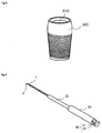
- Fig. 8 illustrates a schematic perspective view of a fixture used in a prior-art implant for reference.
- a drill hole is drilled in the bone and then, a fixture 300 illustrated in Fig. 8 is embedded in the drill hole.
- the gingiva of the patient is injured and swollen and thus, return to a healthy state of the gingiva is waited for and then, the abutment and the artificial tooth are mounted on the fixture 300.
- An internal cavity 310 is provided in the fixture 300, and by screwing the abutment in this internal cavity 310, the abutment can be fixed to the fixture 300.
- a diameter of the internal cavity 310 of the fixture 300 used in an implant is usually very small at approximately 3 mm or less, and there is limitation in keeping the internal cavity 310 in a clean state during an operation of an implant, attachment of a healing cap and an abutment and the like.
- a prior-art brush used for polishing of teeth is attached to a high-speed rotating device called a micro-motor having been used for polishing of teeth in order to clean the internal cavity 310 of the fixture 300, it is extremely difficult to insert the prior-art brush into only the internal cavity 310 of the fixture 300, and it is also likely that the gingiva in the vicinity of the fixture 300 of the patient is injured.
- this small-diameter resin twisted brush is a twisted brush in which helical brush bristles are formed around a shaft member and can be used in the perpendicular direction to the surface of a tooth, but it is difficult to use it in the vertical direction to the bone serving as a base of a tooth, that is, in the vertical direction along the surface of the tooth (Patent Literature 1).
- the interdental brush represented by the small-diameter resin twisted brush should be used in the perpendicular direction to the surface of a tooth and its working mechanism is totally different from a brush for cleaning the inside of an implant used in the horizontal direction to the surface of a tooth and cannot be referred to in development of a brush for cleaning the inside of an implant.
- JP 3615752 B1 shows a resin twisting brush, wherein the material of the shaft part of an interdental brush (the twisting brush) is formed of a resin material shape restorability and elasticity to provide the brush with proper elasticity, shape restorability, and flexibility and prevent the shaft part from being deformed nor broken so that the shaft part can be deformed and easily inserted when the interdental brush (the twisting brush) is inserted into a narrow portion such as a hourglass-shaped interdental space.
- an interdental cleaning assisting tool well matching the three-dimensional shape of an interdental part capable of maintaining straightness without causing permanent deformation, when the shaft part is bent despite the fact that the tool can be inserted into the interdental part restricted in the inserting direction, provides less pain and less uncomfortable feeling, when the tool comes into contact with a tooth and a gum during the cleaning operation.
- US 6,179,617 B1 shows a micro-brush which is provided to remove the smear layer that remains in the root canal after the pulp, bacteria, and related irritants have been mechanically and chemically removed from the root canal using files and sodium hypochlorite.
- the brush includes a shaft or shank and a tapered brush section extending from the distal end of the shank.
- the brush section includes a plurality of bristles extending radially from a central wire base.
- the bristles can be formed in a reverse thread pattern.
- the shank can be provided with a handle for manual use or the shank can be adapted to be received in a rotary, sonic, or ultrasonic handpiece to impart rotational or vibratory motion to the micro-brush.
- JP H11 33042 A shows an antibacterial interdental brush which prevents the growth of harmful microorganisms such as bacteria and mold.
- the interdental brush shows a brush member comprising a brush part, in which bristles are each twisted with a metallic wire over a predetermined length from its end. Furthermore, the wire is buried in a handle member by a predetermined length. At least the bristles contain 0.1 to 5.0 wt.% antibacterial zeolite acting as an inorganic antibacterial agent in a thermoplastic synthetic resin.
- the present invention has an object to provide means for keeping an internal cavity of an implant or more specifically, an internal cavity provided in a fixture constituting an implant in a clean state by a simple operation without injuring the gingiva around the fixture.
- the object of the invention is solved by the features of the independent claim.
- the inventor has made a keen examination and as a result, found out that a brush for cleaning the inside of an implant provided with a twisted brush part in which a helical brush bristles are formed around a wire rod, an intermediate columnar part to which the twisted brush part is fixed, and a main columnar part to which the intermediate columnar part is fixed meets the object of the present invention and has completed the present invention.
- the present invention is to provide
- one of the present invention is to provide the brush for cleaning the inside of an implant described in the above-described [1], in which
- one of the present invention is to provide the brush for cleaning the inside of an implant described in any one of the above-described [1] or [2], in which
- one of the present invention is to provide the brush for cleaning the inside of an implant described in any one of the above-described [1] to [3], in which
- one of the present invention is to provide the brush for cleaning the inside of an implant described in any one of the above-described [1] to [4], in which
- one of the present invention is to provide the brush for cleaning the inside of an implant described in any one of the above-described [1] to [5], in which
- one of the present invention is to provide the brush for cleaning the inside of an implant described in any one of the above-described [1] to [6], in which
- the brush for cleaning the inside of an implant according to the present invention has the twisted brush part in which helical brush bristles are formed.
- the brush for cleaning the inside of an implant has a structure in which, by inserting the helical brush bristles into the internal cavity provided inside the implant, that is, in the fixture constituting the implant and rotating the helical brush bristles in a certain direction, a bone fragment, gingival fragment, blood and the like of a patient or food residues and the like generated during usual daily meals and the like inside the internal cavity adhering to the helical brush bristles can be discharged to the main columnar part side of the brush for cleaning the inside of an implant. As a result, the inside of an implant can be cleaned.
- the major axis center line of the intermediate columnar part matches the major axis center line of the main columnar part, vibration in the brush for cleaning the inside of an implant generated when the brush for cleaning the inside of an implant is rotated can be prevented.
- the projection plane of the internal columnar part from the major axis center line direction to the plane perpendicular to the major axis center line of the intermediate columnar part is contained within the projection plane of the twisted brush part from the major axis center line direction to the plane perpendicular to the major axis center line of the intermediate columnar part; and the projection plane of the intermediate columnar part from the major axis center line direction to the plane perpendicular to the major axis center line of the intermediate columnar part is contained within the projection plane of the major columnar part from the major axis center line direction to the plane perpendicular to the major axis center line direction of the main columnar part.
- the intermediate columnar part has an outer diameter equal to or smaller than the maximum outer diameter of the twisted brush part in which the helical brush bristles are formed and an outer diameter equal to or smaller than the maximum outer diameter of the main columnar part.
- the helical brush bristles when the helical brush bristles are inserted into the internal cavity provided in the fixture constituting the implant, since visibility to the twisted brush part in which the helical brush bristles are formed is excellent, the helical brush bristles can be inserted into the internal cavity provided in the fixture constituting the implant appropriately and easily, which is excellent in handling.
- the rotating intermediate columnar part has a configuration which is not easily brought into contact with a gingival part in the vicinity of the fixture constituting the implant, an effect that the gingival part in the vicinity of the fixture is not injured during cleaning of the inside of an implant can be exerted.
- the brush bristles can be installed on the distal end portion of the twisted brush part in the major axis center line direction of the intermediate columnar part. By using the brush bristles, the internal cavity provided in the fixture constituting the implant can be cleaned.
- At least one selected from a group consisting of the wire rod of the twisted brush part, the intermediate columnar part, and the main columnar part can be covered by a resin.
- a resin By means of covering, even if the fixture constituting the implant and the brush for cleaning the inside of an implant are formed of different metal materials, ionization of the metal materials can be prevented, and generation of impurities can be prevented. Moreover, corrosion of the fixture constituting the implant and the brush for cleaning the inside of an implant can be prevented.
- prognostic defects such as loosening of a screw inside the implant, breakage of the implant and the like can be prevented.
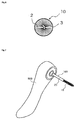
- Fig. 1 is a schematic front view illustrating a brush for cleaning the inside of an implant according to the present invention.
- Fig. 2 is a schematic perspective view illustrating the brush for cleaning the inside of an implant according to the present invention.
- the brush 100 for cleaning the inside of an implant according to the present invention is provided with a twisted brush part 10 in which helical brush bristles are formed around a wire rod.
- the brush 100 for cleaning the inside of an implant according to the present invention is provided with an intermediate columnar part 20 to which the twisted brush part 10 is fixed and a main columnar part 30 to which the intermediate columnar part is fixed.
- the main columnar part 30 has a rotating device mounting part 40 on an end portion on the side opposite to an end portion to which the intermediate columnar part 20 is fixed.
- this rotating device mounting part 40 By fitting and fixing this rotating device mounting part 40 in a rotating device (not shown), the brush 100 for cleaning the inside of an implant can be rotated and used.
- Figs. 2 to 5 are schematic diagrams for explaining steps of forming the twisted brush part 10 in which the helical brush bristles are formed around the wire rod.
- the intermediate columnar part 20 and the main columnar part 30 illustrated in Fig. 3 are formed of metal such as stainless, titanium and the like.
- metal such as stainless, titanium and the like.
- inorganic materials such as ceramics and the like and organic materials such as super engineer plastic and the like can be also used.
- the intermediate columnar part 20 and the main columnar part 30 illustrated in Fig. 3 can be formed by cutting a metal rod while rotating the same or the like.
- the rotating device mounting part 40 of the main columnar part 30 can be also obtained by cutting the main columnar part 30 while rotating the same or the like and cutting the same using a cutting and polishing device such as a grinder or the like.
- the similar shape can be also formed by forming a mold in advance and pouring molten metal or the like into the mold and cooling and then removing the mold.
- both end portions 1a and 1b obtained by smoothly bending a single wire rod 1 at the center part and folding it back are fixed to one end of the intermediate columnar part 20.
- the wire rod 1 is formed of metal such as stainless and the like.
- a method of fixing the both end portions 1a and 1b of the wire rod 1 to the one end of the intermediate columnar part 20 a method of welding or the like, for example, can be cited.
- a method of applying a high voltage to each of the both end portions 1a and 1b of the wire rod and the intermediate columnar part 20 and by connecting the both by bringing them into contact with each other and melting them or the like can be cited.
- the resin fibers 2 used in the present invention are not particularly limited but synthetic fibers with flexibility such as polyethylene, polypropylene, polyester and the like can be cited, for example.
- a distal end portion 3 of the twisted brush part 10 can be formed having a smooth curved shape, and a helical brush bristles can be formed around the wire rod.
- the distal end portion 3 of the twisted brush part 10 used in the present invention has a smooth curved shape and has no portion folded back at a sharp angle and thus, an accident that a stress is applied to a sharp angle portion of the twisted brush part 10 when the twisted brush part 10 is rotated and the wire rod 1 is fractured and the like can be prevented.
- the distal end portion 3 of the rotating twisted brush part 10 touches the gingiva in an oral cavity or the like by mistake, since the distal end portion 3 of the twisted brush part 10 has a smooth curved shape, the gingiva in the oral cavity or the like is not injured.
- the gingiva in the oral cavity or the like If the gingiva in the oral cavity or the like is injured, it bleeds, but since this bleeding can be prevented, contamination inside the implant caused by bleeding or the like can be prevented.
- Fig. 6 is a schematic front view illustrating a state in which the brush 100 for cleaning the inside of an implant according to the present invention is observed from the same direction as a direction of an arrow A in Fig. 4 .
- a projection plate of the intermediate columnar part 20 from a major axis center line direction to a plane perpendicular to the major axis center line (the arrow A direction in Fig. 4 ) of the intermediate columnar part 20 is contained within a projection plane of the twisted brush part 10 from the major axis center line to a plane perpendicular to the major axis center line of the intermediate columnar part 20.
- a sectional area by the plane perpendicular to the major axis center line of the intermediate columnar part 20 has a size equal to or smaller than a sectional area of the twisted brush part 10 by the plane perpendicular to the major axis center line of the intermediate columnar part 20, when the twisted brush part 10 is inserted into the internal cavity provided in the fixture constituting the implant while being rotated, the rotating intermediate columnar part 20 does not touch the gingival part in the vicinity of the fixture, and the gingival part in the vicinity of the fixture is not injured while the internal cavity provided in the fixture constituting the implant is being cleaned.
- a length in the major axis direction of the intermediate columnar part 20 used in the present invention is, assuming the length in the major axis direction of the twisted brush part 10 is 1, within a range of 0.8 to 2.0. That is, the brush 100 for cleaning the inside of an implant according to the present invention is provided with the intermediate columnar part 20 having a length long enough to clean the internal cavity provided in the fixture constituting the implant as compared with the twisted brush part 10.
- the main columnar part 30 of the rotating brush 100 for cleaning the inside of an implant does not touch the gingival part in the vicinity of the fixture, and the gingival part in the vicinity of the fixture is not injured during cleaning of the internal cavity provided in the fixture constituting the implant.
- the projection plane of the intermediate columnar part 20 from the major axis center line direction to the plane perpendicular to the major axis center line of the intermediate columnar part 20 is contained within the projection plane of the main columnar part 30 from the major axis center line direction to the plane perpendicular to the major axis center line of the main columnar part 30.
- the brush 100 for cleaning the inside of an implant according to the present invention can maintain sufficient strength as a whole. Moreover, sufficient fixing strength can be also exerted when the brush 100 for cleaning the inside of an implant according to the present invention is mounted on the rotating device.
- Each of the intermediate columnar part 20 and the main columnar part 30 used in the present invention may have a polygonal columnar shape but in view of prevention of an injury when the rotated brush 100 for cleaning the inside of an implant according to the present invention touches other teeth, the gingiva and the like in the oral cavity, the shape is preferably columnar.
- the major axis center line of the intermediate columnar part in the present invention means the center of gravity line in the major axis direction of the intermediate columnar part
- the major axis center line of the main columnar part means the center of gravity line in the major axis direction in the main columnar part except the rotating device mounting part.
- the reason why the rotating device mounting part 40 is excluded from the main columnar part 30 is that since the rotating device mounting part 40 has a portion partially cut off by a plane in parallel with the major axis direction of the main columnar part 30, the position of the center of gravity line is different between the portion with the rotating device mounting part 40 in the main columnar part 30 and the portion without the rotating device mounting part 40.
- the center of gravity line in the major axis direction of the twisted brush part 10 preferably matches each other.
- the maximum diameter of the twisted brush part 10 is preferably within a range of 0. 7 to 1.5, more preferably within a range of 0.8 to 1.3 or still more preferably within a range of 0.9 to 1.1.
- the maximum diameter of the intermediate columnar part 20 is preferably within a range of 0.9 to 0.1, more preferably within a range of 0.8 to 0.2 or still more preferably within a range of 0.7 to 0.4.
- the length of the intermediate columnar part 20 is, as described above, within a range of 0.8 to 2.0, assuming that the length of the twisted brush part 10 is 1.
- the length of the twisted brush part 10 means the length from one end of the intermediate columnar part 20 on the side where the twisted brush part 10 is installed to the distal end of the twisted brush part 10 on the basis of the major axis center line of the intermediate columnar part 20. The same applies to the following.
- the length in the major axis direction of the twisted brush part 10 is 8 mm ⁇ 3 mm
- the length in the major axis direction of the intermediate columnar part 20 is 9 mm ⁇ 3 mm
- the length in the major axis direction of the main columnar part 30 is 17 mm ⁇ 5 mm.
- the maximum diameter of the intermediate columnar part 20 appearing on a section in the direction perpendicular to the major axis center line direction of the intermediate columnar part 20 is 1 mm ⁇ 0.3 mm
- a maximum diameter of the main columnar part 30 appearing on a section in the direction perpendicular to the major axis center line direction of the main columnar part 30 is 2.1 mm ⁇ 1 mm.
- At least one selected from a group consisting of the wire rod 1 of the twisted brush part 10, the intermediate columnar part 20, and the main columnar part 30 is preferably covered by a resin.
- the resin used for the covering can be a polyolefin resin such as polyethylene, polypropylene and the like, a polyester resin such as polyethylene terephthalate, polybutylene terephthalate and the like, poyfluoride resin such as polytetrafluoroethylene and the like, for example.
- the shape or the size of the brush 100 for cleaning the inside of an implant according to the present invention can be changed as appropriate and selected in accordance with the shape or size of the implant to be actually used.
- Fig. 7 is a schematic perspective view for explaining a state in which the brush 100 for cleaning the inside of an implant obtained by Embodiment 1 is attached to a rotating device 500.
- the brush 100 for cleaning the inside of an implant according to the present invention has the rotating device mounting part 40 on the main columnar part 30.
- the rotating device mounting part 40 includes a notched part 41 provided in a planar direction horizontal to the major axis direction of the main columnar part 20 and a groove part 42 provided in an outer periphery of the main columnar part.
- the brush 100 for cleaning the inside of an implant can be fixed to the rotating device 500.
- the twisted brush part 10 of the brush 100 for cleaning the inside of an implant is inserted by the rotating device 500 into the inside of the implant, that is, the internal cavity provided in the fixture constituting the implant while being rotated.
- a rotation speed of the brush 100 for cleaning the inside of an implant is preferably within a range of 100 to 1000 rpm, more preferably within a range of 200 to 900 rpm or further preferably within a range of 400 to 800 rpm.
- the rotation speed of the brush 100 for cleaning the inside of an implant is less than 100 rpm, cleaning efficiency of the inside of the implant is low, while if the speed exceeds 1000 rpm, there is a concern that the brush injures the gingiva in the vicinity of the fixture constituting the implant.
- a rotation direction of the brush 100 for cleaning the inside of an implant is determined by a helical shape of the twisted brush 10.
- the twisted brush 10 used in the present invention has a helical shape.
- Fig. 6 when the twisted brush 10 is seen from the front, if the helical shape if formed leftwise, by rotating the twisted brush 10 in the left direction when seen from the front, adhering objects such as a bone fragment, a gingival fragment, blood or the like of the patient adhering to the helical brush of the twisted brush 10 or food residues generated during daily meals and the like are discharged to the side opposite to the distal end of the twisted brush 10, that is, to the intermediate columnar part 20 side.
- adhering objects such as a bone fragment, a gingival fragment, blood or the like of the patient adhering to the helical brush of the twisted brush 10 or food residues generated during daily meals and the like are discharged to the side opposite to the distal end of the twisted brush 10, that is, to the intermediate columnar part 20 side.
- cleaning of the inside of an implant can be carried out simply and safely by using the brush 100 for cleaning the inside of an implant.
- a brush 200 for cleaning the inside of an implant according to an embodiment 2 is a variation of the brush 100 for cleaning the inside of an implant according to Embodiment 1.
- the brush 100 for cleaning the inside of an implant according to Embodiment 1 brush bristles are not installed on the distal end portion 3 of the twisted brush part 10 in the major axis center line direction of the intermediate columnar part 20.
- the brush 200 for cleaning the inside of an implant according to Embodiment 2 is different in a point that brush bristles are installed on the distal end portion of the twisted brush part in the major axis center line direction of the intermediate columnar part 20.
- the brush 200 for cleaning the inside of an implant according to Embodiment 2 is similar to the case of the brush 100 for cleaning the inside of an implant according to Embodiment 1.
- Figs. 9 to 13 are schematic diagrams for explaining a step of forming the twisted brush part 10 in which helical brush bristles are formed on the distal end portion of the twisted brush part.
- annular part 4 is formed at a distal end of the twisted brush part by twisting the wire rod 1 of the twisted brush part.
- a large number of resin fibers 11 are passed through the annular part 4 at the distal end of the twisted brush part.
- the large number of resin fibers 11 are folded in the major axis center line direction of the intermediate columnar part 20.
- Brush bristles can be formed on the distal end portion of the twisted brush part illustrated in Fig. 13 by a method of bundling the peripheries of the large number of folded resin fibers 11 with a resin fiber, a method of fixing the periphery of the large number of folded resin fibers 11 with a resin tape and the like.
- the brush 200 for cleaning the inside of an implant according to Embodiment 2 has a large number of resin fibers 11 which are brush bristles on the distal end portion of the twisted brush part, brush bristles can be installed on the distal end portion of the twisted brush part in the major axis center line direction of the intermediate columnar part. By means of these brush bristles, the internal cavity provided in the fixture constituting the implant can be cleaned.
Landscapes
- Health & Medical Sciences (AREA)
- Dentistry (AREA)
- Epidemiology (AREA)
- Life Sciences & Earth Sciences (AREA)
- Animal Behavior & Ethology (AREA)
- General Health & Medical Sciences (AREA)
- Public Health (AREA)
- Veterinary Medicine (AREA)
- Oral & Maxillofacial Surgery (AREA)
- Orthopedic Medicine & Surgery (AREA)
- Brushes (AREA)
Claims (7)
- Brosse pour nettoyer l'intérieur d'un implant (100, 200) comprenant :une partie de brosse torsadée (10) formée en agençant un grand nombre de fibres en parallèle dans une direction perpendiculaire à un fil machine (1), et ensuite en torsadant ledit fil machine (1) de manière à réaliser des poils de brosse en hélice autour dudit fil machine (1) ;une partie intermédiaire en colonne (20) ; etune partie principale en colonne (30), dans laquelle le fil machine (1) utilisé dans ladite partie de brosse torsadée (10) est fixé sur une première des portions terminales de ladite partie intermédiaire en colonne (20) de telle façon que ladite partie de brosse torsadée (10) et ladite partie intermédiaire en colonne (20) sont fixées l'une à l'autre ;ladite partie principale en colonne (30) est fixée sur l'autre portion terminale de ladite partie intermédiaire en colonne (20) ;ladite partie principale en colonne (30) comporte une partie de montage (40) pour dispositif rotatif (500) sur l'autre portion terminale à l'opposé de la première portion terminale à laquelle est fixée ladite partie intermédiaire en colonne (20) ;une ligne centrale de l'axe principal de ladite partie intermédiaire en colonne (20) concorde avec une ligne centrale de l'axe principal de ladite partie principale en colonne (30) ; etcaractérisée en ce que, sur la base de la direction de la ligne centrale de l'axe principal de ladite partie intermédiaire en colonne (20), en supposant que la longueur de ladite partie de brosse torsadée (10) est égale à 1, la longueur de ladite partie intermédiaire en colonne (20) est dans une plage de 0,8 à 2,0, et lesdites fibres sont réalisées en résine.
- Brosse pour nettoyer l'intérieur d'un implant (100, 200) selon la revendication 1, dans laquelle
un plan en projection de ladite partie intermédiaire en colonne (20) depuis la direction de la ligne centrale de l'axe principal (A) sur un plan perpendiculaire à la ligne centrale de l'axe principal de ladite partie intermédiaire en colonne (20) est contenu dans un plan de projection de ladite partie de brosse torsadée (10) depuis la direction de la ligne centrale de l'axe principal (A) sur le plan perpendiculaire à la ligne centrale de l'axe principal de ladite partie intermédiaire en colonne (20) ; et
le plan de projection de ladite partie intermédiaire en colonne (20) depuis la direction de la ligne centrale de l'axe principal (A) sur le plan perpendiculaire à la ligne centrale de l'axe principal de ladite partie intermédiaire en colonne (20) est contenu dans le plan de projection de ladite partie principale en colonne (30) depuis la direction de la ligne centrale de l'axe principal (A) sur le plan perpendiculaire à la direction de la ligne centrale de l'axe principal (A) de ladite partie principale en colonne (30). - Brosse pour nettoyer l'intérieur d'un implant (100, 200) selon la revendication 2, dans laquelle ladite partie de brosse torsadée (10) est formée en agençant un grand nombre de fibres de résine (2) en parallèle avec deux parties parallèles de fil machine (1) obtenues en cintrant et en repliant en douceur un fil machine (1), et ensuite en torsadant lesdites deux parties parallèles de fil machine (1) de manière à former une portion d'extrémité distale (3) de ladite partie de brosse torsadée (10) ayant une forme incurvée en douceur, et en formant des poils de brosse en hélice autour dudit fil machine (1).
- Brosse pour nettoyer l'intérieur d'un implant (100, 200) selon la revendication 3, dans laquelle la partie de montage (40) pour dispositif rotatif (500) de ladite partie principale en colonne (30) inclut une partie en encoche (41) prévue dans une direction planaire horizontale par rapport à la direction de l'axe principal (A) de ladite partie principale en colonne (30), et une partie en rainure (42) prévue dans une périphérie extérieure de ladite partie principale en colonne (30).
- Brosse pour nettoyer l'intérieur d'un implant (100, 200) selon la revendication 4, dans laquelle la portion d'extrémité distale (3) de ladite partie de brosse torsadée (10) est dotée de poils de brosse dans la direction de la ligne centrale de l'axe principal (A) de ladite partie intermédiaire en colonne (20).
- Brosse pour nettoyer l'intérieur d'un implant (100, 200) selon la revendication 5, dans laquelle au moins un élément choisi parmi un groupe comprenant le fil machine (1) de ladite partie de brosse torsadée (10), ladite partie intermédiaire en colonne (20), et la partie principale en colonne (30) est couvert par une résine (2, 5, 11).
- Brosse pour nettoyer l'intérieur d'un implant (100, 200) selon la revendication 6, dans laquelle une longueur, dans la direction de l'axe principal (A), de ladite partie de brosse torsadée (10) est de 8 mm ± 3 mm, une longueur, dans la direction de l'axe principal (A) de ladite partie intermédiaire en colonne (20) est de 9 mm ± 3 mm, et une longueur, dans la direction de l'axe principal (A) de ladite partie principale en colonne (30) est de 17 mm ± 5 mm ; et
un diamètre maximum apparaissant sur une section de la direction perpendiculaire à la direction de l'axe principal (A) de ladite partie intermédiaire en colonne (20) est de 1 mm ± 0,3 mm, et un diamètre maximum apparaissant sur une section dans la direction perpendiculaire à la direction de l'axe principal (A) de ladite partie principale en colonne (30) est de 2,1 mm ± 1 mm.
Applications Claiming Priority (2)
| Application Number | Priority Date | Filing Date | Title |
|---|---|---|---|
| JP2010253319 | 2010-11-11 | ||
| PCT/JP2011/006304 WO2012063496A1 (fr) | 2010-11-11 | 2011-11-10 | Brosse pour le nettoyage de l'intérieur d'un implant |
Publications (3)
| Publication Number | Publication Date |
|---|---|
| EP2638877A1 EP2638877A1 (fr) | 2013-09-18 |
| EP2638877A4 EP2638877A4 (fr) | 2014-07-16 |
| EP2638877B1 true EP2638877B1 (fr) | 2016-01-20 |
Family
ID=46050661
Family Applications (1)
| Application Number | Title | Priority Date | Filing Date |
|---|---|---|---|
| EP11839715.7A Active EP2638877B1 (fr) | 2010-11-11 | 2011-11-10 | Brosse pour le nettoyage de l'intérieur d'un implant |
Country Status (5)
| Country | Link |
|---|---|
| US (1) | US9579176B2 (fr) |
| EP (1) | EP2638877B1 (fr) |
| JP (1) | JP5170721B2 (fr) |
| KR (1) | KR101426666B1 (fr) |
| WO (1) | WO2012063496A1 (fr) |
Families Citing this family (8)
| Publication number | Priority date | Publication date | Assignee | Title |
|---|---|---|---|---|
| SE532467C2 (sv) * | 2007-12-27 | 2010-01-26 | Numat As | Implantatrengöringsverktyg för rengöring av ett metalliskt implantat |
| SE537094C2 (sv) * | 2011-11-14 | 2015-01-07 | Labrida As | Bioresorberbart rengöringsverktyg för implantat |
| KR101477496B1 (ko) | 2013-09-06 | 2014-12-31 | (주) 시원 | 치과용 임플란트 세정기구 |
| US11147363B2 (en) * | 2017-03-03 | 2021-10-19 | Donna Federici | Volume and curl enhancing hairbrush |
| JP7261558B2 (ja) * | 2018-10-17 | 2023-04-20 | 株式会社橋本ブラシ製作所 | 口腔ケア用ブラシの製造方法及び口腔ケア用ブラシ |
| JP7385272B2 (ja) * | 2020-05-11 | 2023-11-22 | ヤマトエスロン株式会社 | 歯間ブラシ |
| US20240122679A1 (en) * | 2022-10-18 | 2024-04-18 | Jagjot RANDHAWA | Mechanical dental bonding scrubbing apparatus |
| USD1079284S1 (en) * | 2024-11-21 | 2025-06-17 | Binbin Liu | Cleaning brush for washing machine |
Family Cites Families (13)
| Publication number | Priority date | Publication date | Assignee | Title |
|---|---|---|---|---|
| CH667382A5 (en) | 1986-04-25 | 1988-10-14 | Sven Jarby | Tooth cleaning tool for dental operations - is rotary brush with bristles helically clamped between twisted ends of bent wire |
| JP2575925B2 (ja) * | 1990-05-11 | 1997-01-29 | 松下電器産業株式会社 | トラッキング制御装置 |
| DE4019830A1 (de) * | 1990-06-21 | 1992-01-02 | Inoue Attachment K K | Buerste vom leistungsverbindungstyp zum reinigen eines zwischenzahnbereichs oder aehnlichem |
| DE9313034U1 (de) * | 1993-08-31 | 1993-10-28 | Georg Karl Geka-Brush Gmbh, 91572 Bechhofen | Reinigungsgerät |
| JPH08266338A (ja) | 1995-03-30 | 1996-10-15 | Hideo Katase | 歯科インプラント用歯ブラシ |
| JP4097311B2 (ja) * | 1997-01-14 | 2008-06-11 | 株式会社ジーシーデンタルプロダクツ | 歯間ブラシ |
| US6179617B1 (en) | 1998-11-12 | 2001-01-30 | Clifford J. Ruddle | Microbrush for endodontic use |
| JP3434275B2 (ja) * | 2000-12-14 | 2003-08-04 | 淳 高橋 | 電動歯間ブラシ |
| JP2004041260A (ja) * | 2002-07-08 | 2004-02-12 | Atsushi Takahashi | ソフト歯間清掃器具 |
| JP3615752B1 (ja) | 2003-11-18 | 2005-02-02 | 淳 高橋 | 細径樹脂捩じりブラシ |
| JP4108735B1 (ja) | 2007-09-04 | 2008-06-25 | 茂樹 上村 | 歯間ブラシ |
| SE532467C2 (sv) * | 2007-12-27 | 2010-01-26 | Numat As | Implantatrengöringsverktyg för rengöring av ett metalliskt implantat |
| JP2009247585A (ja) * | 2008-04-05 | 2009-10-29 | Atsushi Takahashi | 異形ファイバー樹脂捩りブラシ |
-
2011
- 2011-11-10 EP EP11839715.7A patent/EP2638877B1/fr active Active
- 2011-11-10 WO PCT/JP2011/006304 patent/WO2012063496A1/fr not_active Ceased
- 2011-11-10 KR KR1020137014642A patent/KR101426666B1/ko not_active Expired - Fee Related
- 2011-11-10 JP JP2012537248A patent/JP5170721B2/ja active Active
- 2011-11-10 US US13/884,690 patent/US9579176B2/en not_active Expired - Fee Related
Also Published As
| Publication number | Publication date |
|---|---|
| JPWO2012063496A1 (ja) | 2014-05-12 |
| KR101426666B1 (ko) | 2014-08-05 |
| JP5170721B2 (ja) | 2013-03-27 |
| EP2638877A1 (fr) | 2013-09-18 |
| EP2638877A4 (fr) | 2014-07-16 |
| WO2012063496A1 (fr) | 2012-05-18 |
| US9579176B2 (en) | 2017-02-28 |
| US20130327354A1 (en) | 2013-12-12 |
| KR20130101562A (ko) | 2013-09-13 |
Similar Documents
| Publication | Publication Date | Title |
|---|---|---|
| EP2638877B1 (fr) | Brosse pour le nettoyage de l'intérieur d'un implant | |
| US7713059B2 (en) | Self adjusting instrument | |
| JP4563630B2 (ja) | 歯科器具、及び歯科ウェッジ器具 | |
| KR101501954B1 (ko) | 치주 수술용 견인기 | |
| US20070259307A1 (en) | Instruments having anti-microbial coating | |
| US20160074135A1 (en) | Adjustable dental hand instrument | |
| WO2008036120A1 (fr) | Detartreur dentaire non metallique | |
| US5242301A (en) | All purpose device for dental hygiene with dental implants | |
| JP2018501931A (ja) | 保護先端部付き歯間ブラシ | |
| US20200237485A1 (en) | Dental Restoration Maintenance Apparatus and Method | |
| KR102448279B1 (ko) | 안전와이어가 장착된 임플란트 시술용 헥사 드라이버 | |
| EP3777607A1 (fr) | Brosse à dents | |
| KR101157406B1 (ko) | 치아 또는 치과용 임플란트 주변 이물질 제거솔 | |
| Nerkar et al. | Root canal preparation in primary teeth with nickel-titanium rotary files: A review | |
| Lambrianidis | Therapeutic options for the management of fractured instruments | |
| US10993791B2 (en) | Floss feeder | |
| WO2013135623A1 (fr) | Kit de brosse en poils de titane | |
| WO2017013680A2 (fr) | Lime et fraise à gaine parodontale | |
| RU2000751C1 (ru) | Устройство дл чистки и полировани зубов | |
| DK181883B1 (en) | Intraorally Implant Thread-Surface Cleaner for the use in patients after failure of the implant to jawbone integration | |
| WO2017013681A2 (fr) | Lime et fraise à brosse parodontale | |
| JPH11188050A (ja) | 歯間清掃具 | |
| JP2004033674A (ja) | 歯根状ネジ固定式インプラント用仮封材 | |
| Thomas et al. | Technique | |
| JP2020108595A (ja) | 歯科用器具 |
Legal Events
| Date | Code | Title | Description |
|---|---|---|---|
| PUAI | Public reference made under article 153(3) epc to a published international application that has entered the european phase |
Free format text: ORIGINAL CODE: 0009012 |
|
| 17P | Request for examination filed |
Effective date: 20130528 |
|
| AK | Designated contracting states |
Kind code of ref document: A1 Designated state(s): AL AT BE BG CH CY CZ DE DK EE ES FI FR GB GR HR HU IE IS IT LI LT LU LV MC MK MT NL NO PL PT RO RS SE SI SK SM TR |
|
| A4 | Supplementary search report drawn up and despatched |
Effective date: 20140617 |
|
| RIC1 | Information provided on ipc code assigned before grant |
Ipc: A61C 17/00 20060101AFI20140611BHEP Ipc: A46B 3/18 20060101ALI20140611BHEP Ipc: A46B 13/02 20060101ALI20140611BHEP Ipc: A46D 1/00 20060101ALI20140611BHEP Ipc: A61C 8/00 20060101ALI20140611BHEP |
|
| 17Q | First examination report despatched |
Effective date: 20150317 |
|
| GRAP | Despatch of communication of intention to grant a patent |
Free format text: ORIGINAL CODE: EPIDOSNIGR1 |
|
| INTG | Intention to grant announced |
Effective date: 20150731 |
|
| GRAS | Grant fee paid |
Free format text: ORIGINAL CODE: EPIDOSNIGR3 |
|
| GRAA | (expected) grant |
Free format text: ORIGINAL CODE: 0009210 |
|
| AK | Designated contracting states |
Kind code of ref document: B1 Designated state(s): AL AT BE BG CH CY CZ DE DK EE ES FI FR GB GR HR HU IE IS IT LI LT LU LV MC MK MT NL NO PL PT RO RS SE SI SK SM TR |
|
| REG | Reference to a national code |
Ref country code: GB Ref legal event code: FG4D |
|
| REG | Reference to a national code |
Ref country code: CH Ref legal event code: EP |
|
| REG | Reference to a national code |
Ref country code: IE Ref legal event code: FG4D |
|
| REG | Reference to a national code |
Ref country code: AT Ref legal event code: REF Ref document number: 771353 Country of ref document: AT Kind code of ref document: T Effective date: 20160215 |
|
| REG | Reference to a national code |
Ref country code: DE Ref legal event code: R096 Ref document number: 602011022902 Country of ref document: DE |
|
| REG | Reference to a national code |
Ref country code: CH Ref legal event code: NV Representative=s name: RENTSCH PARTNER AG, CH |
|
| REG | Reference to a national code |
Ref country code: LT Ref legal event code: MG4D Ref country code: NL Ref legal event code: MP Effective date: 20160120 |
|
| REG | Reference to a national code |
Ref country code: AT Ref legal event code: MK05 Ref document number: 771353 Country of ref document: AT Kind code of ref document: T Effective date: 20160120 |
|
| PG25 | Lapsed in a contracting state [announced via postgrant information from national office to epo] |
Ref country code: NL Free format text: LAPSE BECAUSE OF FAILURE TO SUBMIT A TRANSLATION OF THE DESCRIPTION OR TO PAY THE FEE WITHIN THE PRESCRIBED TIME-LIMIT Effective date: 20160120 |
|
| PG25 | Lapsed in a contracting state [announced via postgrant information from national office to epo] |
Ref country code: NO Free format text: LAPSE BECAUSE OF FAILURE TO SUBMIT A TRANSLATION OF THE DESCRIPTION OR TO PAY THE FEE WITHIN THE PRESCRIBED TIME-LIMIT Effective date: 20160420 Ref country code: ES Free format text: LAPSE BECAUSE OF FAILURE TO SUBMIT A TRANSLATION OF THE DESCRIPTION OR TO PAY THE FEE WITHIN THE PRESCRIBED TIME-LIMIT Effective date: 20160120 Ref country code: HR Free format text: LAPSE BECAUSE OF FAILURE TO SUBMIT A TRANSLATION OF THE DESCRIPTION OR TO PAY THE FEE WITHIN THE PRESCRIBED TIME-LIMIT Effective date: 20160120 Ref country code: GR Free format text: LAPSE BECAUSE OF FAILURE TO SUBMIT A TRANSLATION OF THE DESCRIPTION OR TO PAY THE FEE WITHIN THE PRESCRIBED TIME-LIMIT Effective date: 20160421 Ref country code: IT Free format text: LAPSE BECAUSE OF FAILURE TO SUBMIT A TRANSLATION OF THE DESCRIPTION OR TO PAY THE FEE WITHIN THE PRESCRIBED TIME-LIMIT Effective date: 20160120 Ref country code: FI Free format text: LAPSE BECAUSE OF FAILURE TO SUBMIT A TRANSLATION OF THE DESCRIPTION OR TO PAY THE FEE WITHIN THE PRESCRIBED TIME-LIMIT Effective date: 20160120 |
|
| PG25 | Lapsed in a contracting state [announced via postgrant information from national office to epo] |
Ref country code: PT Free format text: LAPSE BECAUSE OF FAILURE TO SUBMIT A TRANSLATION OF THE DESCRIPTION OR TO PAY THE FEE WITHIN THE PRESCRIBED TIME-LIMIT Effective date: 20160520 Ref country code: SE Free format text: LAPSE BECAUSE OF FAILURE TO SUBMIT A TRANSLATION OF THE DESCRIPTION OR TO PAY THE FEE WITHIN THE PRESCRIBED TIME-LIMIT Effective date: 20160120 Ref country code: LT Free format text: LAPSE BECAUSE OF FAILURE TO SUBMIT A TRANSLATION OF THE DESCRIPTION OR TO PAY THE FEE WITHIN THE PRESCRIBED TIME-LIMIT Effective date: 20160120 Ref country code: PL Free format text: LAPSE BECAUSE OF FAILURE TO SUBMIT A TRANSLATION OF THE DESCRIPTION OR TO PAY THE FEE WITHIN THE PRESCRIBED TIME-LIMIT Effective date: 20160120 Ref country code: RS Free format text: LAPSE BECAUSE OF FAILURE TO SUBMIT A TRANSLATION OF THE DESCRIPTION OR TO PAY THE FEE WITHIN THE PRESCRIBED TIME-LIMIT Effective date: 20160120 Ref country code: AT Free format text: LAPSE BECAUSE OF FAILURE TO SUBMIT A TRANSLATION OF THE DESCRIPTION OR TO PAY THE FEE WITHIN THE PRESCRIBED TIME-LIMIT Effective date: 20160120 Ref country code: LV Free format text: LAPSE BECAUSE OF FAILURE TO SUBMIT A TRANSLATION OF THE DESCRIPTION OR TO PAY THE FEE WITHIN THE PRESCRIBED TIME-LIMIT Effective date: 20160120 Ref country code: IS Free format text: LAPSE BECAUSE OF FAILURE TO SUBMIT A TRANSLATION OF THE DESCRIPTION OR TO PAY THE FEE WITHIN THE PRESCRIBED TIME-LIMIT Effective date: 20160520 |
|
| REG | Reference to a national code |
Ref country code: DE Ref legal event code: R097 Ref document number: 602011022902 Country of ref document: DE |
|
| PG25 | Lapsed in a contracting state [announced via postgrant information from national office to epo] |
Ref country code: DK Free format text: LAPSE BECAUSE OF FAILURE TO SUBMIT A TRANSLATION OF THE DESCRIPTION OR TO PAY THE FEE WITHIN THE PRESCRIBED TIME-LIMIT Effective date: 20160120 Ref country code: EE Free format text: LAPSE BECAUSE OF FAILURE TO SUBMIT A TRANSLATION OF THE DESCRIPTION OR TO PAY THE FEE WITHIN THE PRESCRIBED TIME-LIMIT Effective date: 20160120 |
|
| REG | Reference to a national code |
Ref country code: FR Ref legal event code: PLFP Year of fee payment: 6 |
|
| PLBE | No opposition filed within time limit |
Free format text: ORIGINAL CODE: 0009261 |
|
| STAA | Information on the status of an ep patent application or granted ep patent |
Free format text: STATUS: NO OPPOSITION FILED WITHIN TIME LIMIT |
|
| PG25 | Lapsed in a contracting state [announced via postgrant information from national office to epo] |
Ref country code: SK Free format text: LAPSE BECAUSE OF FAILURE TO SUBMIT A TRANSLATION OF THE DESCRIPTION OR TO PAY THE FEE WITHIN THE PRESCRIBED TIME-LIMIT Effective date: 20160120 Ref country code: RO Free format text: LAPSE BECAUSE OF FAILURE TO SUBMIT A TRANSLATION OF THE DESCRIPTION OR TO PAY THE FEE WITHIN THE PRESCRIBED TIME-LIMIT Effective date: 20160120 Ref country code: CZ Free format text: LAPSE BECAUSE OF FAILURE TO SUBMIT A TRANSLATION OF THE DESCRIPTION OR TO PAY THE FEE WITHIN THE PRESCRIBED TIME-LIMIT Effective date: 20160120 Ref country code: SM Free format text: LAPSE BECAUSE OF FAILURE TO SUBMIT A TRANSLATION OF THE DESCRIPTION OR TO PAY THE FEE WITHIN THE PRESCRIBED TIME-LIMIT Effective date: 20160120 |
|
| 26N | No opposition filed |
Effective date: 20161021 |
|
| PG25 | Lapsed in a contracting state [announced via postgrant information from national office to epo] |
Ref country code: BE Free format text: LAPSE BECAUSE OF FAILURE TO SUBMIT A TRANSLATION OF THE DESCRIPTION OR TO PAY THE FEE WITHIN THE PRESCRIBED TIME-LIMIT Effective date: 20160120 |
|
| PG25 | Lapsed in a contracting state [announced via postgrant information from national office to epo] |
Ref country code: SI Free format text: LAPSE BECAUSE OF FAILURE TO SUBMIT A TRANSLATION OF THE DESCRIPTION OR TO PAY THE FEE WITHIN THE PRESCRIBED TIME-LIMIT Effective date: 20160120 Ref country code: BG Free format text: LAPSE BECAUSE OF FAILURE TO SUBMIT A TRANSLATION OF THE DESCRIPTION OR TO PAY THE FEE WITHIN THE PRESCRIBED TIME-LIMIT Effective date: 20160420 |
|
| REG | Reference to a national code |
Ref country code: IE Ref legal event code: MM4A |
|
| PG25 | Lapsed in a contracting state [announced via postgrant information from national office to epo] |
Ref country code: LU Free format text: LAPSE BECAUSE OF NON-PAYMENT OF DUE FEES Effective date: 20161130 |
|
| REG | Reference to a national code |
Ref country code: CH Ref legal event code: PCAR Free format text: NEW ADDRESS: BELLERIVESTRASSE 203 POSTFACH, 8034 ZUERICH (CH) |
|
| REG | Reference to a national code |
Ref country code: FR Ref legal event code: PLFP Year of fee payment: 7 |
|
| PG25 | Lapsed in a contracting state [announced via postgrant information from national office to epo] |
Ref country code: IE Free format text: LAPSE BECAUSE OF NON-PAYMENT OF DUE FEES Effective date: 20161110 |
|
| PG25 | Lapsed in a contracting state [announced via postgrant information from national office to epo] |
Ref country code: HU Free format text: LAPSE BECAUSE OF FAILURE TO SUBMIT A TRANSLATION OF THE DESCRIPTION OR TO PAY THE FEE WITHIN THE PRESCRIBED TIME-LIMIT; INVALID AB INITIO Effective date: 20111110 Ref country code: CY Free format text: LAPSE BECAUSE OF FAILURE TO SUBMIT A TRANSLATION OF THE DESCRIPTION OR TO PAY THE FEE WITHIN THE PRESCRIBED TIME-LIMIT Effective date: 20160120 |
|
| PG25 | Lapsed in a contracting state [announced via postgrant information from national office to epo] |
Ref country code: MK Free format text: LAPSE BECAUSE OF FAILURE TO SUBMIT A TRANSLATION OF THE DESCRIPTION OR TO PAY THE FEE WITHIN THE PRESCRIBED TIME-LIMIT Effective date: 20160120 Ref country code: MC Free format text: LAPSE BECAUSE OF FAILURE TO SUBMIT A TRANSLATION OF THE DESCRIPTION OR TO PAY THE FEE WITHIN THE PRESCRIBED TIME-LIMIT Effective date: 20160120 |
|
| PG25 | Lapsed in a contracting state [announced via postgrant information from national office to epo] |
Ref country code: MT Free format text: LAPSE BECAUSE OF NON-PAYMENT OF DUE FEES Effective date: 20161110 |
|
| PG25 | Lapsed in a contracting state [announced via postgrant information from national office to epo] |
Ref country code: AL Free format text: LAPSE BECAUSE OF FAILURE TO SUBMIT A TRANSLATION OF THE DESCRIPTION OR TO PAY THE FEE WITHIN THE PRESCRIBED TIME-LIMIT Effective date: 20160120 Ref country code: TR Free format text: LAPSE BECAUSE OF FAILURE TO SUBMIT A TRANSLATION OF THE DESCRIPTION OR TO PAY THE FEE WITHIN THE PRESCRIBED TIME-LIMIT Effective date: 20160120 |
|
| PGFP | Annual fee paid to national office [announced via postgrant information from national office to epo] |
Ref country code: GB Payment date: 20231123 Year of fee payment: 13 |
|
| PGFP | Annual fee paid to national office [announced via postgrant information from national office to epo] |
Ref country code: FR Payment date: 20231124 Year of fee payment: 13 Ref country code: DE Payment date: 20231128 Year of fee payment: 13 Ref country code: CH Payment date: 20231201 Year of fee payment: 13 |
|
| REG | Reference to a national code |
Ref country code: DE Ref legal event code: R119 Ref document number: 602011022902 Country of ref document: DE |
|
| REG | Reference to a national code |
Ref country code: CH Ref legal event code: PL |
|
| REG | Reference to a national code |
Ref country code: CH Ref legal event code: PL |
|
| GBPC | Gb: european patent ceased through non-payment of renewal fee |
Effective date: 20241110 |
|
| PG25 | Lapsed in a contracting state [announced via postgrant information from national office to epo] |
Ref country code: CH Free format text: LAPSE BECAUSE OF NON-PAYMENT OF DUE FEES Effective date: 20241130 |
|
| PG25 | Lapsed in a contracting state [announced via postgrant information from national office to epo] |
Ref country code: DE Free format text: LAPSE BECAUSE OF NON-PAYMENT OF DUE FEES Effective date: 20250603 |
|
| PG25 | Lapsed in a contracting state [announced via postgrant information from national office to epo] |
Ref country code: GB Free format text: LAPSE BECAUSE OF NON-PAYMENT OF DUE FEES Effective date: 20241110 |
|
| PG25 | Lapsed in a contracting state [announced via postgrant information from national office to epo] |
Ref country code: FR Free format text: LAPSE BECAUSE OF NON-PAYMENT OF DUE FEES Effective date: 20241130 |