EP2639097A2 - Dispositif de commande, procédé de commande et véhicule à moteur électrique - Google Patents
Dispositif de commande, procédé de commande et véhicule à moteur électrique Download PDFInfo
- Publication number
- EP2639097A2 EP2639097A2 EP12178080.3A EP12178080A EP2639097A2 EP 2639097 A2 EP2639097 A2 EP 2639097A2 EP 12178080 A EP12178080 A EP 12178080A EP 2639097 A2 EP2639097 A2 EP 2639097A2
- Authority
- EP
- European Patent Office
- Prior art keywords
- electric motor
- motor car
- battery
- voltage
- power
- Prior art date
- Legal status (The legal status is an assumption and is not a legal conclusion. Google has not performed a legal analysis and makes no representation as to the accuracy of the status listed.)
- Ceased
Links
Images


Classifications
-
- B—PERFORMING OPERATIONS; TRANSPORTING
- B60—VEHICLES IN GENERAL
- B60L—PROPULSION OF ELECTRICALLY-PROPELLED VEHICLES; SUPPLYING ELECTRIC POWER FOR AUXILIARY EQUIPMENT OF ELECTRICALLY-PROPELLED VEHICLES; ELECTRODYNAMIC BRAKE SYSTEMS FOR VEHICLES IN GENERAL; MAGNETIC SUSPENSION OR LEVITATION FOR VEHICLES; MONITORING OPERATING VARIABLES OF ELECTRICALLY-PROPELLED VEHICLES; ELECTRIC SAFETY DEVICES FOR ELECTRICALLY-PROPELLED VEHICLES
- B60L7/00—Electrodynamic brake systems for vehicles in general
- B60L7/10—Dynamic electric regenerative braking
-
- B—PERFORMING OPERATIONS; TRANSPORTING
- B60—VEHICLES IN GENERAL
- B60L—PROPULSION OF ELECTRICALLY-PROPELLED VEHICLES; SUPPLYING ELECTRIC POWER FOR AUXILIARY EQUIPMENT OF ELECTRICALLY-PROPELLED VEHICLES; ELECTRODYNAMIC BRAKE SYSTEMS FOR VEHICLES IN GENERAL; MAGNETIC SUSPENSION OR LEVITATION FOR VEHICLES; MONITORING OPERATING VARIABLES OF ELECTRICALLY-PROPELLED VEHICLES; ELECTRIC SAFETY DEVICES FOR ELECTRICALLY-PROPELLED VEHICLES
- B60L15/00—Methods, circuits, or devices for controlling the traction-motor speed of electrically-propelled vehicles
- B60L15/20—Methods, circuits, or devices for controlling the traction-motor speed of electrically-propelled vehicles for control of the vehicle or its driving motor to achieve a desired performance, e.g. speed, torque, programmed variation of speed
- B60L15/2009—Methods, circuits, or devices for controlling the traction-motor speed of electrically-propelled vehicles for control of the vehicle or its driving motor to achieve a desired performance, e.g. speed, torque, programmed variation of speed for braking
-
- B—PERFORMING OPERATIONS; TRANSPORTING
- B60—VEHICLES IN GENERAL
- B60L—PROPULSION OF ELECTRICALLY-PROPELLED VEHICLES; SUPPLYING ELECTRIC POWER FOR AUXILIARY EQUIPMENT OF ELECTRICALLY-PROPELLED VEHICLES; ELECTRODYNAMIC BRAKE SYSTEMS FOR VEHICLES IN GENERAL; MAGNETIC SUSPENSION OR LEVITATION FOR VEHICLES; MONITORING OPERATING VARIABLES OF ELECTRICALLY-PROPELLED VEHICLES; ELECTRIC SAFETY DEVICES FOR ELECTRICALLY-PROPELLED VEHICLES
- B60L50/00—Electric propulsion with power supplied within the vehicle
- B60L50/50—Electric propulsion with power supplied within the vehicle using propulsion power supplied by batteries or fuel cells
- B60L50/53—Electric propulsion with power supplied within the vehicle using propulsion power supplied by batteries or fuel cells in combination with an external power supply, e.g. from overhead contact lines
-
- B—PERFORMING OPERATIONS; TRANSPORTING
- B60—VEHICLES IN GENERAL
- B60L—PROPULSION OF ELECTRICALLY-PROPELLED VEHICLES; SUPPLYING ELECTRIC POWER FOR AUXILIARY EQUIPMENT OF ELECTRICALLY-PROPELLED VEHICLES; ELECTRODYNAMIC BRAKE SYSTEMS FOR VEHICLES IN GENERAL; MAGNETIC SUSPENSION OR LEVITATION FOR VEHICLES; MONITORING OPERATING VARIABLES OF ELECTRICALLY-PROPELLED VEHICLES; ELECTRIC SAFETY DEVICES FOR ELECTRICALLY-PROPELLED VEHICLES
- B60L58/00—Methods or circuit arrangements for monitoring or controlling batteries or fuel cells, specially adapted for electric vehicles
- B60L58/10—Methods or circuit arrangements for monitoring or controlling batteries or fuel cells, specially adapted for electric vehicles for monitoring or controlling batteries
- B60L58/12—Methods or circuit arrangements for monitoring or controlling batteries or fuel cells, specially adapted for electric vehicles for monitoring or controlling batteries responding to state of charge [SoC]
-
- B—PERFORMING OPERATIONS; TRANSPORTING
- B60—VEHICLES IN GENERAL
- B60L—PROPULSION OF ELECTRICALLY-PROPELLED VEHICLES; SUPPLYING ELECTRIC POWER FOR AUXILIARY EQUIPMENT OF ELECTRICALLY-PROPELLED VEHICLES; ELECTRODYNAMIC BRAKE SYSTEMS FOR VEHICLES IN GENERAL; MAGNETIC SUSPENSION OR LEVITATION FOR VEHICLES; MONITORING OPERATING VARIABLES OF ELECTRICALLY-PROPELLED VEHICLES; ELECTRIC SAFETY DEVICES FOR ELECTRICALLY-PROPELLED VEHICLES
- B60L7/00—Electrodynamic brake systems for vehicles in general
- B60L7/10—Dynamic electric regenerative braking
- B60L7/14—Dynamic electric regenerative braking for vehicles propelled by AC motors
-
- B—PERFORMING OPERATIONS; TRANSPORTING
- B60—VEHICLES IN GENERAL
- B60L—PROPULSION OF ELECTRICALLY-PROPELLED VEHICLES; SUPPLYING ELECTRIC POWER FOR AUXILIARY EQUIPMENT OF ELECTRICALLY-PROPELLED VEHICLES; ELECTRODYNAMIC BRAKE SYSTEMS FOR VEHICLES IN GENERAL; MAGNETIC SUSPENSION OR LEVITATION FOR VEHICLES; MONITORING OPERATING VARIABLES OF ELECTRICALLY-PROPELLED VEHICLES; ELECTRIC SAFETY DEVICES FOR ELECTRICALLY-PROPELLED VEHICLES
- B60L9/00—Electric propulsion with power supply external to the vehicle
- B60L9/16—Electric propulsion with power supply external to the vehicle using AC induction motors
- B60L9/18—Electric propulsion with power supply external to the vehicle using AC induction motors fed from DC supply lines
-
- B—PERFORMING OPERATIONS; TRANSPORTING
- B60—VEHICLES IN GENERAL
- B60L—PROPULSION OF ELECTRICALLY-PROPELLED VEHICLES; SUPPLYING ELECTRIC POWER FOR AUXILIARY EQUIPMENT OF ELECTRICALLY-PROPELLED VEHICLES; ELECTRODYNAMIC BRAKE SYSTEMS FOR VEHICLES IN GENERAL; MAGNETIC SUSPENSION OR LEVITATION FOR VEHICLES; MONITORING OPERATING VARIABLES OF ELECTRICALLY-PROPELLED VEHICLES; ELECTRIC SAFETY DEVICES FOR ELECTRICALLY-PROPELLED VEHICLES
- B60L2200/00—Type of vehicles
- B60L2200/26—Rail vehicles
-
- B—PERFORMING OPERATIONS; TRANSPORTING
- B60—VEHICLES IN GENERAL
- B60L—PROPULSION OF ELECTRICALLY-PROPELLED VEHICLES; SUPPLYING ELECTRIC POWER FOR AUXILIARY EQUIPMENT OF ELECTRICALLY-PROPELLED VEHICLES; ELECTRODYNAMIC BRAKE SYSTEMS FOR VEHICLES IN GENERAL; MAGNETIC SUSPENSION OR LEVITATION FOR VEHICLES; MONITORING OPERATING VARIABLES OF ELECTRICALLY-PROPELLED VEHICLES; ELECTRIC SAFETY DEVICES FOR ELECTRICALLY-PROPELLED VEHICLES
- B60L2210/00—Converter types
- B60L2210/10—DC to DC converters
- B60L2210/12—Buck converters
-
- B—PERFORMING OPERATIONS; TRANSPORTING
- B60—VEHICLES IN GENERAL
- B60L—PROPULSION OF ELECTRICALLY-PROPELLED VEHICLES; SUPPLYING ELECTRIC POWER FOR AUXILIARY EQUIPMENT OF ELECTRICALLY-PROPELLED VEHICLES; ELECTRODYNAMIC BRAKE SYSTEMS FOR VEHICLES IN GENERAL; MAGNETIC SUSPENSION OR LEVITATION FOR VEHICLES; MONITORING OPERATING VARIABLES OF ELECTRICALLY-PROPELLED VEHICLES; ELECTRIC SAFETY DEVICES FOR ELECTRICALLY-PROPELLED VEHICLES
- B60L2210/00—Converter types
- B60L2210/10—DC to DC converters
- B60L2210/14—Boost converters
-
- B—PERFORMING OPERATIONS; TRANSPORTING
- B60—VEHICLES IN GENERAL
- B60L—PROPULSION OF ELECTRICALLY-PROPELLED VEHICLES; SUPPLYING ELECTRIC POWER FOR AUXILIARY EQUIPMENT OF ELECTRICALLY-PROPELLED VEHICLES; ELECTRODYNAMIC BRAKE SYSTEMS FOR VEHICLES IN GENERAL; MAGNETIC SUSPENSION OR LEVITATION FOR VEHICLES; MONITORING OPERATING VARIABLES OF ELECTRICALLY-PROPELLED VEHICLES; ELECTRIC SAFETY DEVICES FOR ELECTRICALLY-PROPELLED VEHICLES
- B60L2220/00—Electrical machine types; Structures or applications thereof
- B60L2220/10—Electrical machine types
- B60L2220/12—Induction machines
-
- B—PERFORMING OPERATIONS; TRANSPORTING
- B60—VEHICLES IN GENERAL
- B60L—PROPULSION OF ELECTRICALLY-PROPELLED VEHICLES; SUPPLYING ELECTRIC POWER FOR AUXILIARY EQUIPMENT OF ELECTRICALLY-PROPELLED VEHICLES; ELECTRODYNAMIC BRAKE SYSTEMS FOR VEHICLES IN GENERAL; MAGNETIC SUSPENSION OR LEVITATION FOR VEHICLES; MONITORING OPERATING VARIABLES OF ELECTRICALLY-PROPELLED VEHICLES; ELECTRIC SAFETY DEVICES FOR ELECTRICALLY-PROPELLED VEHICLES
- B60L2240/00—Control parameters of input or output; Target parameters
- B60L2240/10—Vehicle control parameters
- B60L2240/12—Speed
-
- B—PERFORMING OPERATIONS; TRANSPORTING
- B60—VEHICLES IN GENERAL
- B60L—PROPULSION OF ELECTRICALLY-PROPELLED VEHICLES; SUPPLYING ELECTRIC POWER FOR AUXILIARY EQUIPMENT OF ELECTRICALLY-PROPELLED VEHICLES; ELECTRODYNAMIC BRAKE SYSTEMS FOR VEHICLES IN GENERAL; MAGNETIC SUSPENSION OR LEVITATION FOR VEHICLES; MONITORING OPERATING VARIABLES OF ELECTRICALLY-PROPELLED VEHICLES; ELECTRIC SAFETY DEVICES FOR ELECTRICALLY-PROPELLED VEHICLES
- B60L2240/00—Control parameters of input or output; Target parameters
- B60L2240/40—Drive Train control parameters
- B60L2240/42—Drive Train control parameters related to electric machines
- B60L2240/423—Torque
-
- B—PERFORMING OPERATIONS; TRANSPORTING
- B60—VEHICLES IN GENERAL
- B60L—PROPULSION OF ELECTRICALLY-PROPELLED VEHICLES; SUPPLYING ELECTRIC POWER FOR AUXILIARY EQUIPMENT OF ELECTRICALLY-PROPELLED VEHICLES; ELECTRODYNAMIC BRAKE SYSTEMS FOR VEHICLES IN GENERAL; MAGNETIC SUSPENSION OR LEVITATION FOR VEHICLES; MONITORING OPERATING VARIABLES OF ELECTRICALLY-PROPELLED VEHICLES; ELECTRIC SAFETY DEVICES FOR ELECTRICALLY-PROPELLED VEHICLES
- B60L2240/00—Control parameters of input or output; Target parameters
- B60L2240/40—Drive Train control parameters
- B60L2240/42—Drive Train control parameters related to electric machines
- B60L2240/427—Voltage
-
- B—PERFORMING OPERATIONS; TRANSPORTING
- B60—VEHICLES IN GENERAL
- B60L—PROPULSION OF ELECTRICALLY-PROPELLED VEHICLES; SUPPLYING ELECTRIC POWER FOR AUXILIARY EQUIPMENT OF ELECTRICALLY-PROPELLED VEHICLES; ELECTRODYNAMIC BRAKE SYSTEMS FOR VEHICLES IN GENERAL; MAGNETIC SUSPENSION OR LEVITATION FOR VEHICLES; MONITORING OPERATING VARIABLES OF ELECTRICALLY-PROPELLED VEHICLES; ELECTRIC SAFETY DEVICES FOR ELECTRICALLY-PROPELLED VEHICLES
- B60L2260/00—Operating Modes
- B60L2260/10—Temporary overload
- B60L2260/16—Temporary overload of electrical drive trains
- B60L2260/167—Temporary overload of electrical drive trains of motors or generators
-
- Y—GENERAL TAGGING OF NEW TECHNOLOGICAL DEVELOPMENTS; GENERAL TAGGING OF CROSS-SECTIONAL TECHNOLOGIES SPANNING OVER SEVERAL SECTIONS OF THE IPC; TECHNICAL SUBJECTS COVERED BY FORMER USPC CROSS-REFERENCE ART COLLECTIONS [XRACs] AND DIGESTS
- Y02—TECHNOLOGIES OR APPLICATIONS FOR MITIGATION OR ADAPTATION AGAINST CLIMATE CHANGE
- Y02T—CLIMATE CHANGE MITIGATION TECHNOLOGIES RELATED TO TRANSPORTATION
- Y02T10/00—Road transport of goods or passengers
- Y02T10/60—Other road transportation technologies with climate change mitigation effect
- Y02T10/64—Electric machine technologies in electromobility
-
- Y—GENERAL TAGGING OF NEW TECHNOLOGICAL DEVELOPMENTS; GENERAL TAGGING OF CROSS-SECTIONAL TECHNOLOGIES SPANNING OVER SEVERAL SECTIONS OF THE IPC; TECHNICAL SUBJECTS COVERED BY FORMER USPC CROSS-REFERENCE ART COLLECTIONS [XRACs] AND DIGESTS
- Y02—TECHNOLOGIES OR APPLICATIONS FOR MITIGATION OR ADAPTATION AGAINST CLIMATE CHANGE
- Y02T—CLIMATE CHANGE MITIGATION TECHNOLOGIES RELATED TO TRANSPORTATION
- Y02T10/00—Road transport of goods or passengers
- Y02T10/60—Other road transportation technologies with climate change mitigation effect
- Y02T10/70—Energy storage systems for electromobility, e.g. batteries
-
- Y—GENERAL TAGGING OF NEW TECHNOLOGICAL DEVELOPMENTS; GENERAL TAGGING OF CROSS-SECTIONAL TECHNOLOGIES SPANNING OVER SEVERAL SECTIONS OF THE IPC; TECHNICAL SUBJECTS COVERED BY FORMER USPC CROSS-REFERENCE ART COLLECTIONS [XRACs] AND DIGESTS
- Y02—TECHNOLOGIES OR APPLICATIONS FOR MITIGATION OR ADAPTATION AGAINST CLIMATE CHANGE
- Y02T—CLIMATE CHANGE MITIGATION TECHNOLOGIES RELATED TO TRANSPORTATION
- Y02T10/00—Road transport of goods or passengers
- Y02T10/60—Other road transportation technologies with climate change mitigation effect
- Y02T10/72—Electric energy management in electromobility
Definitions
- Embodiments described herein generally relate to a control device, a control method, and an electric motor car.
- a main motor is activated as a generator and a regenerated current from the generator is returned to the overhead contact line etc.
- a regenerative brake control which has same function with a status where a car is braked, is used.
- a battery may be mounted on the conventional electric motor car.
- batteries are respectively installed in plural trailer cars constituting the electric motor car.
- the respective batteries mounted on the respective trailer cars in a distributed state are connected in parallel to each other through a power line, and the power line is drawn through the train.
- the battery voltage is increased to a high voltage by a step-up chopper installed inside the vehicle when the vehicle starts to run. That is, the step-up chopper applies a battery voltage increased up to a rated voltage necessary for an inverter that generates power for driving the motor.
- the battery voltage is designed to be lower than the voltage of the overhead contact line in many cases in order to receive power from the overhead contact line.
- the regeneration efficiency of the main motor is defined by the main circuit voltage in the regenerative brake control when the main motor rotates at a high speed. Accordingly, when the necessary brake force exceeds the electric brake force which may be regenerated based on the main circuit voltage, the brake force necessary for stopping or decelerating the vehicle is not sufficiently obtained. As a result, there is a need to use an air brake. When the air brake is used, energy is wasted due to the heat generation, which causes a problem that the regeneration efficiency decreases.
- an aspect of embodiments provides a control device for an electric motor car comprising: a switch which is installed between a power supply source and a power line drawn through the electric motor car; a battery which supplies power to a main motor of the electric motor car; a step-up unit, which is installed between the power line and the battery, configured to increase a voltage; and a control unit which breaks a connection between the power supply source and the power line using the switch when braking the electric motor car, increases the power supplied from the battery using the step-up unit, and performs regenerative braking in the main motor to which the increased power is supplied.
- the electric motor car control device which improves the regeneration efficiency is provided.
- Fig. 1 is a diagram illustrating a configuration of a main circuit of an electric motor car control device 100 of an electric motor car according to a first embodiment.
- the electric motor car control device 100 receives power by connecting a contactor 101 to a power supply source (not illustrated) (for example, an overhead contact line, a third rail, or the like), Then, the electric motor car control device 100 is connected to a power line 102 through the contactor 101 from the overhead contact line.
- a power supply source not illustrated
- the contactor 101 is installed between the overhead contact line and the power line 102 which is drawn through the electric motor car, and is controlled by a train control management system (hereinafter, referred to as a TCMS) 150 so that the contactor 101 is connected to or disconnected from the overhead contact line.
- a train control management system hereinafter, referred to as a TCMS
- the power line 102 is connected to the respective constituents such as an inverter and a charger through high-speed breakers 103_1, 103_2, and 103_3. Then, the electric motor car control device 100 includes the train control management system (TCMS) 150.
- TCMS train control management system
- the TCMS 150 controls the respective constituents of the electric motor car control device 100.
- the TCMS 150 may control the contactor 101 or a step-up/step-down chopper 120. Further, the TCMS 150 may realize the regenerative braking using main motors 108_1 and 108_2.
- the electric motor car control device 100 is placed on a carriage, and main motors 108_1 and 108_2 are mechanically connected to vehicle wheels so as to apply a drive force or a brake force thereto.
- the voltage of the power which is supplied from the overhead contact line to the power line 102 is exemplified as 600 V, but the voltage value is not limited thereto, and the appropriate voltage may be supplied in accordance with the embodiment.
- a resistor 104_1, a switching element 105_1, a reactor 109_1, a capacitor 106_1, an inverter 107_1, and the main motor 108_1 are connected to the power line 102 through the high-speed breaker 103_1.
- the TCMS 150 When the inverter 107_1 performs a power running operation by the power supplied from the battery 110, the TCMS 150 does not operate the step-up/step-down chopper 120, and the power supplied from the battery 110 reaches the power line 102 through a diode 125. Accordingly, when the battery voltage is DC 600 V, the voltage of the power line 102 also becomes DC 600 V.
- the TCMS 150 performs control in which the switching element 105_1 is turned off and the resistor 104_1 and the capacitor 106_1 are connected in series to each other so as to charge the capacitor 106_1. After the capacitor 106_1 is charged, the switching element 105_1 is turned on, and power is supplied to the capacitor 106_1 and the inverter 107_1 connected in parallel to each other.
- the power supply target is not limited to the battery 110, and may be the overhead contact line.
- the electric motor car control device 100 allows the main motor 108_1 1 to serve as a generator, so that kinetic energy is converted into electric energy. Accordingly, a regenerated current lreg flows to the power line 102.
- a resistor 104_2, a switching element 105_2, a reactor 109_2, a capacitor 106_2, an inverter 107_2, and the main motor 108_2 are connected to the power line 102 through the high-speed breaker 103_2 so as to perform the above-described operation.
- the battery 110 and the step-up/step-down chopper 120 are connected to the power line 102 through the high-speed breaker 103_3.
- the battery 110 supplies power to the main motors 108_1 and 108_2 through the step-up/step-down chopper 120 and the inverters 107_1 and 107_2. Further, the battery 110 may supply power to the TCMS 150 or the respective units inside the electric motor car. Further, the battery 110 is charged by the regenerative braking through the electric brake using the main motors 108_1 and 108_2.
- the step-up/step-down chopper 120 is installed between the power line 102 and the battery 110, and includes a reactor 127, a capacitor 126, the diode 125 of the upper arm, an IGBT 122 of the upper arm, a diode 124 of the lower arm, an IGBT 123 of the lower arm, and a reactor 121. Then, the TCMS 150 increases or decreases the power by controlling any one of the IGBT 122 of the upper arm and the IGBT 123 of the lower arm. Accordingly, the power supplied from the battery 110 may be increased or decreased.
- the respective inverters 107_1 and 107_2 which drive the main motors 108_1 and 108_2 are connected to the power line 102.
- the step-up/step-down chopper 120 is connected between the power line 102 and the battery 110.
- the electric motor car control device 100 drives the electric motor car by the power supplied from the battery or the power supplied from the overhead contact line in a power running mode. Further, the electric motor car control device 100 enables the entire regenerative electric brake by increasing the power using the step-up/step-down chopper 120 during the regenerative braking from the high speed. Next, the reason why the voltage is increased will be described.
- Fig. 2 is a diagram illustrating a relation between the main motor induced voltage and the speed when braking the vehicle.
- the horizontal axis indicates the speed of the vehicle
- the vertical axis indicates the main motor current value and the regenerated current value.
- the relation may be expressed by a line 201 representing the characteristics of the main motor current and a line 202 representing the regenerated current.
- the TCMS 150 performs acceleration by the control in which the torque values of the main motors 108_1 and 108_2 are decreased.
- the supplement corresponding to a difference in current 210 is needed using the air brake when the voltage of the power line 102 is DC 600 V.
- the electric motor car control device 100 changes the power line voltage, through the power running operation and the regeneration operation, by performing the charge control to the battery 110 of the step-up/step-down chopper 120.
- the electric motor car control device 100 since the region where the constant current flows in the main motor current is widened by increasing the voltage of the power line 102 to DC 800 V, entire kinetic energy may be recycled by the electric brake through the regeneration operation using the entire electric brake when braking the electric motor car.
- the overhead contact line connected to the power line 102 is DC 600 V, the power line 102 may not be increased to DC 800 V while being connected to the overhead contact line.
- the TCMS 150 activates the main motors 108_1 and 108_2 as the generator, the contactor 101 is controlled so that the connection to the overhead contact line is interrupted when performing regenerative braking using the electric brake. After the interruption, the TCMS 150 controls the step-up/step-down chopper 120 so that the power supplied from the battery is increased and hence the voltage of the power line 102 is increased to DC 800 V.
- the current lreg which is regenerated by the electric brake flows as a charging input current to the step-up/step-down chopper 120.
- the TCMS 150 controls the step-up/step-down chopper 120 in a step-down mode, and charges the battery 110 of DC 600 V by decreasing the voltage from DC 800 V to DC 600 V.
- the TCMS 150 may perform control so that the voltage of the power line 102 is changed in response to the speed of the vehicle.
- the TCMS 150 determines whether the voltage is increased by the step-up/step-down chopper 120 based on whether the speed is equal to or faster than the reference speed Vt when enabling the electric brake. For example, when it is determined that the speed of the vehicle is equal to or faster than the reference speed Vt, the TCMS 150 controls the step-up/step-down chopper 120 so that the power supplied from the battery 110 is increased to DC 800 V.
- the reference speed indicates a speed in which the value of the regenerated current when enabling the electric brake by the battery voltage of the battery 110 becomes equal to or larger than the value of the current flowing to the main motors 108_1 and 108_2.
- the regenerative braking may be performed by the electric brake using DC 600 V.
- the regenerative braking may be performed by the electric brake using DC 600 V.
- the TCMS 150 when it is determined that the speed is equal to or faster than the reference speed Vt, the TCMS 150 first starts the regenerative braking using the electric brake at DC 600 V. Then, the TCMS 150 may control the contactor 101 so that the connection to the overhead contact line is interrupted and the voltage is increased by the step-up/step-down chopper 120 before the regenerated current exceeds the boundary line 201 of Fig. 2 .
- the TCMS 150 detects an overhead contact line voltage using an overhead contact line voltage detection unit (not illustrated), matches the voltage of the power line 102 to the overhead contact line voltage, and connects the contactor 101 thereto.
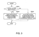
- FIG. 3 is a flowchart illustrating the above-described procedure in the electric motor car control device 100 according to the embodiment.
- the TCMS 150 of the electric motor car control device 100 determines whether the range of a state of charge (hereinafter, referred to as an SOC) of the battery 110 is sufficient (for example, a full charged value, a predetermined value or more, and the like) (step S301).
- SOC state of charge
- the TCMS 150 supplies the power supplied from the battery 110 to the inverters 107_1 and 107_2 so as to drive the main motors 108_1 and 108_2, whereby the power running operation of the vehicle is performed (step S302).
- the TCMS 150 drives the main motors 108_1 and 108_2 by the power supplied from the overhead contact line connected through the contactor 101, whereby the power running operation of the vehicle is performed (step S303).
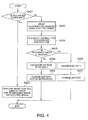
- FIG. 4 is a flowchart illustrating the above-described procedure in the electric motor car control device 100 according to the embodiment.
- the TCMS 150 of the electric motor car control device 100 determines whether the range of the SOC of the battery 110 is sufficient (for example, a full charged value or a predetermined value or more) (step S401).
- the TCMS 150 When it is determined that the range of the SOC of the battery 110 is sufficient (Yes in step S401), the TCMS 150 maintains the connection to the overhead contact line using the contactor 101, and the TCMS 150 performs the brake control by using any one or more of the air (mechanic) brake and the electric brake (step S402).
- the regenerated current which is generated by the electric brake is returned to the overhead contact line.
- a heat radiation process may be performed as heat through a resistor or the like.
- the TCMS 150 determines that the range of the SOC of the battery 110 is not sufficient (No in step S401)
- the TCMS 150 first activates the main motors 108_1 and 108_2 as the generator so as to start the regenerative braking using the electric brake (step S403).
- the TCMS 150 controls the contactor 101 so that the connection between the overhead contact line and the power line 102 is interrupted (step S404).
- the TCMS 150 determines whether the speed of the vehicle is equal to or faster than the reference speed which may be controlled by the electric brake using DC 600 V illustrated in Fig. 2 (step S405). Furthermore, the reference speed is set to a predetermined speed, and in the embodiment, the reference speed is set to the reference speed Vt illustrated in Fig. 2 .
- the TCMS 150 When it is determined that the speed is slower than the reference speed Vt which may be controlled by the electric brake (No in step S405), the TCMS 150 maintains the power line 102 at DC 600 V, normally turns on the IGBT 122, and normally turns off the IGBT 123 (step S406). Accordingly, the TCMS 150 does not increase or decrease the voltage using the step-up/step-down chopper 120, but performs the regenerative braking through the electric brake using the main motors 108_1 and 108_2, so that the battery 110 is charged by the regenerated current without causing a switching loss (step S407).
- the TCMS 150 increases the voltage of the power line 102 to DC 800 V by using the step-up/step-down chopper 120 (step S407).
- the regenerative braking through the electric brake using the main motors 108_1 and 108_2 at DC 800 V is started.
- the TCMS 150 decreases the inflowing regenerated current to DC 600 V in the step-down mode of the step-up/step-down chopper 120 and charges the battery 110 (step S409).
- the TCMS 150 performs control in which the voltage of the power line 102 is increased to a high voltage by using the step-up/step-down chopper 120 as described above during the regeneration.
- the inverters 107_1 and 107_2 transfer the regenerated energy to the power line 102
- the voltage of the power line 102 increases in a state where there is no portion recieving the regenerated energy. Therefore, in order to maintain the increasing voltage at the reference voltage of the high voltage (in the embodiment, DC 800 V), the TCMS 150 performs control in which the charging current to the battery 110 is increased when the voltage of the power line 102 becomes larger than the reference voltage and the charging current to the battery 110 is decreased when the voltage becomes smaller than the reference voltage.
- the increased voltage may have a voltage value which may be used for the regenerative braking using the electric brake without using the air (mechanic) brake.
- the loss of the charging unit may be reduced.
- the TCMS 150 may return the voltage of the power line 102 to DC 600 V by using the step-up/step-down chopper 120.
- the TCMS 150 may control the contactor 101 so that the overhead contact line and the power line 102 are connected to each other. In this case, the regenerated current may be returned to the overhead contact line.
- a table illustrating the correlation between the speed of the vehicle and the regenerated current (or the main motors 108_1 and 108_2) for each voltage of the power line 102 indicated by Fig. 2 is stored in a storage unit (not illustrated), and the TCMS 150 may determine whether to perform a step-up operation by referring to the table.
- the TCMS 150 performs the step-up/step-down control using the step-up/step-down chopper 120 in response to the correlation between the speed of the vehicle and the regenerated current, that is, whether the speed is included in the speed region which is defined by the boundary line 201 of Fig. 2 . Accordingly, the more specific regenerative braking may be realized.
- the voltage in the power running mode of the vehicle is the battery voltage.
- the voltage in the power running mode is not limited to the battery voltage of the battery 110. Therefore, in the modified example 3, the TCMS 150 performs a step-up operation using the step-up/step-down chopper 120 in the power running mode.
- the TCMS 150 increases the voltage of the power line 102 in the power running mode by increasing the voltage using the step-up/step-down chopper 120 in the power running mode. Accordingly, the power running performance may be improved.
- the electric motor car control device 100 drives the vehicle by the battery voltage in the power running mode.
- the voltage is increased to the high voltage by the step-up/step-down chopper 120 during the electric braking (the regenerative braking) from the high speed, the entire regenerative electric braking may be performed. Accordingly, entire kinetic energy is converted into electric energy, so that it may be returned to the battery 110. Accordingly, the regeneration efficiency improves.
- the high regeneration efficiency is realized with the above-described configuration, whereby the mounted battery amount may be decreased.
- the contactor enables or disables the connection of the overhead contact line to the power line drawn through the electric motor car.
- the invention is not limited to the contactor, and a semiconductor switch may be used. Further, the equivalents may be used.
- any unit capable of performing the electric connection and disconnection may be used.
- the step-up/step-down chopper is used in the embodiment of the specification.
- the invention is not limited to the step-up/step-down chopper, and the function of the inverter may be used as described in the paragraph '0051'. Further, the equivalents may be used, and any unit capable of increasing or decreasing the voltage may be used.
Landscapes
- Engineering & Computer Science (AREA)
- Power Engineering (AREA)
- Transportation (AREA)
- Mechanical Engineering (AREA)
- Life Sciences & Earth Sciences (AREA)
- Sustainable Development (AREA)
- Sustainable Energy (AREA)
- Electric Propulsion And Braking For Vehicles (AREA)
- Dc-Dc Converters (AREA)
Applications Claiming Priority (1)
| Application Number | Priority Date | Filing Date | Title |
|---|---|---|---|
| JP2012060063A JP5766640B2 (ja) | 2012-03-16 | 2012-03-16 | 電気車制御装置 |
Publications (2)
| Publication Number | Publication Date |
|---|---|
| EP2639097A2 true EP2639097A2 (fr) | 2013-09-18 |
| EP2639097A3 EP2639097A3 (fr) | 2015-08-12 |
Family
ID=47076040
Family Applications (1)
| Application Number | Title | Priority Date | Filing Date |
|---|---|---|---|
| EP12178080.3A Ceased EP2639097A3 (fr) | 2012-03-16 | 2012-07-26 | Dispositif de commande, procédé de commande et véhicule à moteur électrique |
Country Status (4)
| Country | Link |
|---|---|
| US (1) | US8543275B1 (fr) |
| EP (1) | EP2639097A3 (fr) |
| JP (1) | JP5766640B2 (fr) |
| CN (1) | CN103303155B (fr) |
Cited By (6)
| Publication number | Priority date | Publication date | Assignee | Title |
|---|---|---|---|---|
| EP3059115A1 (fr) * | 2015-02-20 | 2016-08-24 | Vossloh Kiepe GmbH | Systeme de batterie de vehicule |
| WO2017025399A1 (fr) * | 2015-08-07 | 2017-02-16 | Siemens Aktiengesellschaft | Dispositif et procédé d'entrée d'un véhicule ferroviaire dans une station puis de fonctionnement de celui-ci sans ligne aérienne |
| WO2018091701A1 (fr) * | 2016-11-21 | 2018-05-24 | Bombardier Transportation Gmbh | Réseau électrique pour un véhicule ferroviaire, véhicule ferroviaire et procédé d'exploitation d'un réseau électrique |
| WO2019076810A1 (fr) * | 2017-10-16 | 2019-04-25 | Siemens Mobility GmbH | Agencement de stockage d'énergie et procédé pour faire fonctionner un tel dispositif de stockage d'énergie |
| EP3681776A1 (fr) * | 2017-09-15 | 2020-07-22 | FMS Advisers B.V. | Système d'alimentation de voie ferrée et procédé associé |
| EP3681775A1 (fr) * | 2017-09-15 | 2020-07-22 | FMS Advisers | Système d'alimentation de chemin de fer et procédés associés |
Families Citing this family (6)
| Publication number | Priority date | Publication date | Assignee | Title |
|---|---|---|---|---|
| CN104136263B (zh) * | 2012-02-28 | 2016-08-17 | 三菱电机株式会社 | 车厢内信息显示系统以及供电方法 |
| SE538656C2 (en) * | 2014-10-30 | 2016-10-11 | Scania Cv Ab | Method and system for switching from a first power supply path to a second power supply path |
| JP6762243B2 (ja) * | 2017-02-07 | 2020-09-30 | 株式会社日立製作所 | 鉄道車両用電力変換装置 |
| CN110834543B (zh) * | 2019-10-28 | 2022-08-23 | 江苏大学 | 电动车辆电涡流制动与再生制动的耦合系统及控制方法 |
| TWI708472B (zh) * | 2020-03-31 | 2020-10-21 | 義守大學 | 換流裝置 |
| JP7443167B2 (ja) * | 2020-06-22 | 2024-03-05 | 株式会社東芝 | 蓄電装置、電気車制御装置、及び鉄道システム |
Citations (4)
| Publication number | Priority date | Publication date | Assignee | Title |
|---|---|---|---|---|
| JP2001037004A (ja) * | 1999-07-26 | 2001-02-09 | Hitachi Ltd | インバータ式電気車制御装置 |
| JP2001352607A (ja) | 2000-06-06 | 2001-12-21 | Hitachi Ltd | バッテリ駆動の鉄道列車 |
| JP2002369306A (ja) * | 2001-06-04 | 2002-12-20 | Railway Technical Res Inst | 電気車の電気ブレーキ装置 |
| JP2007104899A (ja) * | 2001-12-25 | 2007-04-19 | Toshiba Corp | 電力変換装置 |
Family Cites Families (26)
| Publication number | Priority date | Publication date | Assignee | Title |
|---|---|---|---|---|
| JPS63174501A (ja) * | 1987-01-14 | 1988-07-19 | Toshiba Corp | 電気車の制御装置 |
| JPH06103984B2 (ja) * | 1989-08-23 | 1994-12-14 | 東洋電機製造株式会社 | 昇降圧チョッパ装置 |
| JP3612745B2 (ja) * | 1994-09-20 | 2005-01-19 | 株式会社デンソー | 車両用運動特性制御装置 |
| JP4200512B2 (ja) * | 1998-10-20 | 2008-12-24 | 幸雄 大田 | 電動車両の動力装置 |
| JP2002369308A (ja) * | 2001-06-12 | 2002-12-20 | Railway Technical Res Inst | 電気車両システム |
| US6812656B2 (en) * | 2002-02-27 | 2004-11-02 | Railpower Technologies Corp. | Sequenced pulse width modulation method and apparatus for controlling and powering a plurality of direct current motors |
| JP3989450B2 (ja) * | 2004-02-20 | 2007-10-10 | 財団法人鉄道総合技術研究所 | 回路装置及び車両運行システム |
| JP4643355B2 (ja) * | 2005-05-09 | 2011-03-02 | 株式会社東芝 | 電気車制御装置 |
| EP1885055A4 (fr) * | 2005-05-26 | 2011-05-25 | Mitsubishi Electric Corp | Module de commande de moteur a courant alternatif a vitesse variable |
| JP4500217B2 (ja) * | 2005-06-06 | 2010-07-14 | 財団法人鉄道総合技術研究所 | 回路装置 |
| JP3927584B2 (ja) * | 2005-10-26 | 2007-06-13 | 三菱電機株式会社 | 自動車用動力制御装置 |
| CA2657758C (fr) * | 2006-08-09 | 2013-03-26 | Mitsubishi Electric Corporation | Convertisseur d'alimentation et controleur y faisant appel pour materiel roulant a moteur electrique |
| JP4746525B2 (ja) * | 2006-11-30 | 2011-08-10 | 株式会社東芝 | 電気車制御装置 |
| JP5184798B2 (ja) * | 2007-03-12 | 2013-04-17 | 川崎重工業株式会社 | 充放電制御装置及び充放電制御方法 |
| JP4546988B2 (ja) * | 2007-04-27 | 2010-09-22 | 株式会社日立製作所 | 電力変換器の制御装置 |
| JP4875633B2 (ja) * | 2008-01-17 | 2012-02-15 | 三菱重工業株式会社 | 車両及びその充電制御方法 |
| JP2009273198A (ja) * | 2008-04-30 | 2009-11-19 | Kawasaki Heavy Ind Ltd | 電池駆動車両のパワーフロー制御方法および制御装置 |
| JP5065222B2 (ja) * | 2008-10-17 | 2012-10-31 | トヨタ自動車株式会社 | 車両制御システム |
| EP2340957B1 (fr) * | 2008-10-23 | 2018-08-29 | Mitsubishi Electric Corporation | Dispositif de commande de propulsion pour voiture électrique |
| WO2010119510A1 (fr) * | 2009-04-14 | 2010-10-21 | トヨタ自動車株式会社 | Dispositif de commande de puissance |
| JP5558022B2 (ja) * | 2009-04-15 | 2014-07-23 | 株式会社東芝 | 電気車の蓄電制御装置及び蓄電制御方法 |
| JP5385728B2 (ja) * | 2009-08-28 | 2014-01-08 | 公益財団法人鉄道総合技術研究所 | 制御方法及び制御装置 |
| JP5452371B2 (ja) * | 2010-06-01 | 2014-03-26 | 株式会社日立製作所 | 鉄道車両の駆動装置 |
| JP4977772B2 (ja) * | 2010-07-01 | 2012-07-18 | 株式会社日立製作所 | 駆動制御装置及び電気車 |
| JP2012182912A (ja) * | 2011-03-01 | 2012-09-20 | Toyota Motor Corp | 電動車両およびその制御方法 |
| JP5295470B1 (ja) * | 2012-01-30 | 2013-09-18 | 三菱電機株式会社 | 電気車の推進制御装置およびその制御方法 |
-
2012
- 2012-03-16 JP JP2012060063A patent/JP5766640B2/ja not_active Expired - Fee Related
- 2012-07-26 EP EP12178080.3A patent/EP2639097A3/fr not_active Ceased
- 2012-07-30 US US13/561,281 patent/US8543275B1/en not_active Expired - Fee Related
- 2012-08-20 CN CN201210297384.9A patent/CN103303155B/zh not_active Expired - Fee Related
Patent Citations (4)
| Publication number | Priority date | Publication date | Assignee | Title |
|---|---|---|---|---|
| JP2001037004A (ja) * | 1999-07-26 | 2001-02-09 | Hitachi Ltd | インバータ式電気車制御装置 |
| JP2001352607A (ja) | 2000-06-06 | 2001-12-21 | Hitachi Ltd | バッテリ駆動の鉄道列車 |
| JP2002369306A (ja) * | 2001-06-04 | 2002-12-20 | Railway Technical Res Inst | 電気車の電気ブレーキ装置 |
| JP2007104899A (ja) * | 2001-12-25 | 2007-04-19 | Toshiba Corp | 電力変換装置 |
Cited By (11)
| Publication number | Priority date | Publication date | Assignee | Title |
|---|---|---|---|---|
| EP3059115A1 (fr) * | 2015-02-20 | 2016-08-24 | Vossloh Kiepe GmbH | Systeme de batterie de vehicule |
| WO2017025399A1 (fr) * | 2015-08-07 | 2017-02-16 | Siemens Aktiengesellschaft | Dispositif et procédé d'entrée d'un véhicule ferroviaire dans une station puis de fonctionnement de celui-ci sans ligne aérienne |
| EP3307583A1 (fr) * | 2015-08-07 | 2018-04-18 | Siemens Aktiengesellschaft | Dispositif et procédé d'entrée d'un véhicule ferroviaire dans une station puis de fonctionnement de celui-ci sans ligne aérienne |
| US10793006B2 (en) | 2015-08-07 | 2020-10-06 | Siemens Mobility GmbH | Device and a method for operating a rail vehicle without an overhead line |
| WO2018091701A1 (fr) * | 2016-11-21 | 2018-05-24 | Bombardier Transportation Gmbh | Réseau électrique pour un véhicule ferroviaire, véhicule ferroviaire et procédé d'exploitation d'un réseau électrique |
| CN110023132A (zh) * | 2016-11-21 | 2019-07-16 | 庞巴迪运输有限公司 | 用于有轨车辆的电网络、有轨车辆和用于运行电网络的方法 |
| EP3681776A1 (fr) * | 2017-09-15 | 2020-07-22 | FMS Advisers B.V. | Système d'alimentation de voie ferrée et procédé associé |
| EP3681775A1 (fr) * | 2017-09-15 | 2020-07-22 | FMS Advisers | Système d'alimentation de chemin de fer et procédés associés |
| WO2019076810A1 (fr) * | 2017-10-16 | 2019-04-25 | Siemens Mobility GmbH | Agencement de stockage d'énergie et procédé pour faire fonctionner un tel dispositif de stockage d'énergie |
| CN111278676A (zh) * | 2017-10-16 | 2020-06-12 | 西门子交通有限公司 | 储能装置和运行这种储能装置的方法 |
| RU2737871C1 (ru) * | 2017-10-16 | 2020-12-04 | Сименс Мобилити Гмбх | Энергоаккумулирующее устройство и способ эксплуатации указанного энергоаккумулирующего устройства |
Also Published As
| Publication number | Publication date |
|---|---|
| US20130245868A1 (en) | 2013-09-19 |
| EP2639097A3 (fr) | 2015-08-12 |
| US8543275B1 (en) | 2013-09-24 |
| CN103303155B (zh) | 2016-01-20 |
| CN103303155A (zh) | 2013-09-18 |
| JP2013198195A (ja) | 2013-09-30 |
| JP5766640B2 (ja) | 2015-08-19 |
Similar Documents
| Publication | Publication Date | Title |
|---|---|---|
| US8543275B1 (en) | Control device, control method, and electric motor car | |
| EP2918442B1 (fr) | Système de charge/décharge | |
| JP5382238B2 (ja) | ハイブリッド車両およびその制御方法 | |
| JP4960407B2 (ja) | 車両用駆動電源装置 | |
| KR102302783B1 (ko) | 차량 구동 시스템 및 방법 | |
| CN105050854B (zh) | 电源控制装置 | |
| WO2011021266A1 (fr) | Convertisseur d'énergie pour la propulsion d'une voiture électrique | |
| EP2918441B1 (fr) | Dispositif de charge/décharge | |
| JP2012500164A (ja) | エレベータドライブの線電流およびエネルギ貯蔵の制御 | |
| JP5413017B2 (ja) | 車両用電源装置 | |
| US11097620B2 (en) | Circuit system for railroad vehicle | |
| US20130032416A1 (en) | Ultracapacitor soft-start apparatus and method | |
| JP6673046B2 (ja) | 電気自動車用の電源システム | |
| KR100579298B1 (ko) | 환경 차량의 보조 배터리 충전 제어방법 | |
| JP2013133061A (ja) | ハイブリッド車 | |
| WO2018066624A1 (fr) | Dispositif de commande de système d'alimentation | |
| JP6240023B2 (ja) | 電力変換装置及びそれを備えた鉄道車両 | |
| JP6178597B2 (ja) | 電力システム | |
| JP5921420B2 (ja) | ハイブリッド車両 | |
| JP2010178593A (ja) | 車両の制御装置 | |
| JP2010063298A (ja) | 主回路システム、電源供給方法 | |
| JP2015167466A (ja) | 鉄道車両用駆動装置 | |
| WO2014097415A1 (fr) | Système de charge/décharge et procédé de charge/décharge | |
| JP2012006565A (ja) | 車両用制御装置 | |
| JP2020100243A (ja) | 車両の蓄熱制御装置 |
Legal Events
| Date | Code | Title | Description |
|---|---|---|---|
| PUAI | Public reference made under article 153(3) epc to a published international application that has entered the european phase |
Free format text: ORIGINAL CODE: 0009012 |
|
| AK | Designated contracting states |
Kind code of ref document: A2 Designated state(s): AL AT BE BG CH CY CZ DE DK EE ES FI FR GB GR HR HU IE IS IT LI LT LU LV MC MK MT NL NO PL PT RO RS SE SI SK SM TR |
|
| AX | Request for extension of the european patent |
Extension state: BA ME |
|
| PUAL | Search report despatched |
Free format text: ORIGINAL CODE: 0009013 |
|
| AK | Designated contracting states |
Kind code of ref document: A3 Designated state(s): AL AT BE BG CH CY CZ DE DK EE ES FI FR GB GR HR HU IE IS IT LI LT LU LV MC MK MT NL NO PL PT RO RS SE SI SK SM TR |
|
| AX | Request for extension of the european patent |
Extension state: BA ME |
|
| RIC1 | Information provided on ipc code assigned before grant |
Ipc: B60L 15/20 20060101ALI20150707BHEP Ipc: B60L 11/18 20060101ALI20150707BHEP Ipc: B60L 9/18 20060101ALI20150707BHEP Ipc: B60L 7/10 20060101AFI20150707BHEP Ipc: B60L 7/14 20060101ALI20150707BHEP |
|
| 17P | Request for examination filed |
Effective date: 20160211 |
|
| RBV | Designated contracting states (corrected) |
Designated state(s): AL AT BE BG CH CY CZ DE DK EE ES FI FR GB GR HR HU IE IS IT LI LT LU LV MC MK MT NL NO PL PT RO RS SE SI SK SM TR |
|
| 17Q | First examination report despatched |
Effective date: 20160726 |
|
| STAA | Information on the status of an ep patent application or granted ep patent |
Free format text: STATUS: EXAMINATION IS IN PROGRESS |
|
| STAA | Information on the status of an ep patent application or granted ep patent |
Free format text: STATUS: THE APPLICATION HAS BEEN REFUSED |
|
| 18R | Application refused |
Effective date: 20171026 |