EP2639152A2 - Anbringung von Flugzeugrippen an Holme mit variabler Geometrie - Google Patents
Anbringung von Flugzeugrippen an Holme mit variabler Geometrie Download PDFInfo
- Publication number
- EP2639152A2 EP2639152A2 EP13154386.0A EP13154386A EP2639152A2 EP 2639152 A2 EP2639152 A2 EP 2639152A2 EP 13154386 A EP13154386 A EP 13154386A EP 2639152 A2 EP2639152 A2 EP 2639152A2
- Authority
- EP
- European Patent Office
- Prior art keywords
- ring
- rib
- spar
- tubular
- tubular spar
- Prior art date
- Legal status (The legal status is an assumption and is not a legal conclusion. Google has not performed a legal analysis and makes no representation as to the accuracy of the status listed.)
- Granted
Links
Images



Classifications
-
- B—PERFORMING OPERATIONS; TRANSPORTING
- B64—AIRCRAFT; AVIATION; COSMONAUTICS
- B64C—AEROPLANES; HELICOPTERS
- B64C3/00—Wings
- B64C3/18—Spars; Ribs; Stringers
- B64C3/185—Spars
-
- B—PERFORMING OPERATIONS; TRANSPORTING
- B64—AIRCRAFT; AVIATION; COSMONAUTICS
- B64C—AEROPLANES; HELICOPTERS
- B64C3/00—Wings
- B64C3/18—Spars; Ribs; Stringers
- B64C3/187—Ribs
-
- B—PERFORMING OPERATIONS; TRANSPORTING
- B64—AIRCRAFT; AVIATION; COSMONAUTICS
- B64C—AEROPLANES; HELICOPTERS
- B64C3/00—Wings
- B64C3/34—Tanks constructed integrally with wings, e.g. for fuel or water
-
- B—PERFORMING OPERATIONS; TRANSPORTING
- B64—AIRCRAFT; AVIATION; COSMONAUTICS
- B64D—EQUIPMENT FOR FITTING IN OR TO AIRCRAFT; FLIGHT SUITS; PARACHUTES; ARRANGEMENT OR MOUNTING OF POWER PLANTS OR PROPULSION TRANSMISSIONS IN AIRCRAFT
- B64D27/00—Arrangement or mounting of power plants in aircraft; Aircraft characterised by the type or position of power plants
- B64D27/02—Aircraft characterised by the type or position of power plants
- B64D27/30—Aircraft characterised by electric power plants
- B64D27/35—Arrangements for on-board electric energy production, distribution, recovery or storage
- B64D27/353—Arrangements for on-board electric energy production, distribution, recovery or storage using solar cells
-
- Y—GENERAL TAGGING OF NEW TECHNOLOGICAL DEVELOPMENTS; GENERAL TAGGING OF CROSS-SECTIONAL TECHNOLOGIES SPANNING OVER SEVERAL SECTIONS OF THE IPC; TECHNICAL SUBJECTS COVERED BY FORMER USPC CROSS-REFERENCE ART COLLECTIONS [XRACs] AND DIGESTS
- Y02—TECHNOLOGIES OR APPLICATIONS FOR MITIGATION OR ADAPTATION AGAINST CLIMATE CHANGE
- Y02T—CLIMATE CHANGE MITIGATION TECHNOLOGIES RELATED TO TRANSPORTATION
- Y02T50/00—Aeronautics or air transport
- Y02T50/50—On board measures aiming to increase energy efficiency
-
- Y—GENERAL TAGGING OF NEW TECHNOLOGICAL DEVELOPMENTS; GENERAL TAGGING OF CROSS-SECTIONAL TECHNOLOGIES SPANNING OVER SEVERAL SECTIONS OF THE IPC; TECHNICAL SUBJECTS COVERED BY FORMER USPC CROSS-REFERENCE ART COLLECTIONS [XRACs] AND DIGESTS
- Y10—TECHNICAL SUBJECTS COVERED BY FORMER USPC
- Y10T—TECHNICAL SUBJECTS COVERED BY FORMER US CLASSIFICATION
- Y10T29/00—Metal working
- Y10T29/49—Method of mechanical manufacture
- Y10T29/49826—Assembling or joining
-
- Y—GENERAL TAGGING OF NEW TECHNOLOGICAL DEVELOPMENTS; GENERAL TAGGING OF CROSS-SECTIONAL TECHNOLOGIES SPANNING OVER SEVERAL SECTIONS OF THE IPC; TECHNICAL SUBJECTS COVERED BY FORMER USPC CROSS-REFERENCE ART COLLECTIONS [XRACs] AND DIGESTS
- Y10—TECHNICAL SUBJECTS COVERED BY FORMER USPC
- Y10T—TECHNICAL SUBJECTS COVERED BY FORMER US CLASSIFICATION
- Y10T403/00—Joints and connections
- Y10T403/32—Articulated members
- Y10T403/32606—Pivoted
- Y10T403/32861—T-pivot, e.g., wrist pin, etc.
Definitions
- This disclosure generally relates to construction of airfoils such as aircraft wings, and deals more particularly with attachment of wing ribs to tubular wing spars having variable cross sectional geometries.
- High altitude, long endurance (HALE) solar powered aircraft have been designed that will remain aloft continuously for extended periods.
- on-board solar arrays generate electricity that is used to power electric propulsion motors, and an electrolyzer that generates hydrogen and oxygen which is stored in on-board tanks.
- the electric propulsion motors may be powered by a fuel cell that uses a combination of the hydrogen and oxygen stored in the tanks to generate electricity.
- the tanks are cyclically pressurized as the hydrogen and oxygen in the storage tanks are repeatedly drawn down and then replenished.
- the aircraft may be fabricated from lightweight structures that are integrated with the aircraft's energy storage system.
- tubular wing spars may function as storage tanks to hold the gaseous hydrogen and oxygen used by the fuel cell to produce electricity.
- Optimum spar weight may be achieved using an unsymmetric laminate construction which, because of interlaminar stresses, warps the spar into an ovoidal cross sectional shape. As pressurized gas is introduced into the spar, the spar gradually deforms and its cross sectional shape changes from an ovoid to nearly circular. As gas is drawn from the spar, its cross sectional shape springs-back to an ovoid.
- Spar deformation caused by this cyclical gas pressurization may result in the transmission of stresses to wing ribs to which the spar may be fixedly attached. These transmitted stresses may alter the shape of the rib and thus the overall shape of the airfoil, thereby affecting the aerodynamic performance of the wing.
- a joint for attaching a rib to a tubular spar that varies in cross sectional shape during flight comprising a ring substantially surrounding and attached to tubular spar; and pivot pins connecting the ring with the rib and allowing relative movement between the rib and the tubular spar as the tubular spar varies in cross sectional shape.
- the ring is compliant and is radially loaded against the tubular spar.
- the ring has a radial stiffness that is less than a radial stiffness of the tubular spar.
- the rib includes a forward portion and a rear portion
- the pivot pins include a first pair of pivot pins pivotally connecting the ring with the forward portion of the rib, and a second pair of pivot pins pivotally connecting the ring with the rear portion of the rib.
- the ring includes first and second halves, and splice joints joining the first and second halves together.
- the ring extends around and engages substantially the entire circumference of the tubular spar, and the rib includes upper and lower gaps into which the ring and the tubular spar may deform.
- the tubular spar varies in cross sectional shape about points of inflection along a curvature of the tubular spar where the curvature changes, and the pivot pins are respectively located substantially at the points of inflection.
- the ring includes first portions having a substantially U-shaped cross section, and second portions having a substantially flat cross sectional shape.
- the ring is formed of a fiber reinforced polymer laminate.
- a joint between a substantially non-deformable structure and a tubular member having a cross sectional shape that deforms about points of inflection along a curvature of the tubular member comprising a ring extending substantially around the circumference of and attached to the tubular member, and pivot pins connecting the ring with the non-deformable structure respectively at the points of inflection.
- the ring is compliant and is radially loaded against the tubular member substantially around the entire circumference of the tubular member, and the ring is configured to remain compliant to the tubular member as the tubular member deforms.
- the ring includes a first portion having a substantially U-shaped cross section, and a second portion includes a substantially flat strap.
- the joint further comprises webs on the rib, and wherein the pivot pins are respectively attached to the webs.
- the ring is formed from a fiber reinforced polymer laminate.
- the ring is in tension and is loaded against the tubular member by the tension, and the ring is sufficiently compliant to change shape as the cross sectional shape of the tubular member deforms.
- a method of attaching an aircraft wing rib to a tubular wing spar having a cross sectional shape that may deform during flight comprising placing a ring around the tubular spar, loading the ring against the tubular spar and pivotally connecting the ring to the rib.
- the loading of the ring against the tubular spar includes tensioning the ring.
- pivotally connecting the ring to the rib includes locating pivotal connections between the rib and the tubular spar at points of inflection along a curvature of the tubular spar.
- placing the ring around the tubular spar includes placing two ring halves around the tubular spar, and splicing the ring halves together.
- the method further includes placing webs on the rib, and wherein pivotally connecting the ring to the rib is performed by pivotally connecting the ring to each of the webs.
- a method of transferring loads between a substantially non-deformable structure and a tubular member having a cross sectional shape that deforms under load comprising pivoting the tubular member relative to the non-deformable structure as the cross sectional shape of the tubular member deforms.
- pivoting the tubular member relative to the non-deformable structure is performed by pivoting the tubular member about points of inflection when a curvature of the tubular member changes due to the deformation of the tubular member.
- the method further comprises transferring loads between the tubular member and the non-deformable structure through a ring surrounding and attached to the tubular member.
- the disclosed embodiments provide a method and a joint for attaching aircraft wing ribs or similar components to a tubular spar that varies in cross sectional shape during flight due to its composite laminate construction configuration and/or to changes in its internal pressurization.
- the method and attachment joint employ pivotal connections strategically located about the circumference of the tubular spar which allow relative motion between the tubular spar and the ribs, thereby isolating the ribs from stresses caused by cross sectional deformation of the spar.
- the pivotal connections include pivot pins located at the points of inflection of the changing cross sectional shape of the spar. Locating the pivot pins at the inflection points may substantially eliminate induced radial deflection of the tubular spar into the rib.
- the pivotal connections may also reduce or prevent a moment or twisting action of the tubular spar from being induced into the rib.
- a joint for attaching an aircraft wing rib to a tubular wing spar that varies in cross sectional shape during flight.
- the joint comprises a ring substantially surrounding and attached to the tubular spar, and pivot pins pivotally connecting the ring with the rib.
- the pivot pins allow relative movement between the rib and the tubular spar as the tubular spar varies in cross sectional shape.
- the ring is compliant and radially loaded against the tubular spar.
- the ring has a radial stiffness less than a radial stiffness of the tubular spar.
- the rib includes forward and rear portions.
- the pivot pins include a first pair of pivot pins pivotally connecting the ring with the forward portion of the rib, and a second pair of pivot pins connecting the ring with the rear portion of the rib.
- the ring may comprise first and second halves that are joined together by splice joints.
- the ring extends around and engages substantially the entire circumference of the tubular spar.
- the tubular spar varies in cross sectional shape about points of inflection, and each of the pivot pins is located substantially at one of the points of inflection.
- the ring may be formed of a fiber reinforced polymer laminate.
- a joint is provided between a non-deformable structure and a tubular member having a cross sectional shape that deforms about points of inflection along a curve of the tubular member.
- the joint comprises a ring extending substantially around the circumference of and attached to the tubular member, and pivot pins connecting the ring with the non-deformable structure respectively at the points of inflection.
- the ring is compliant and is radially loaded against a tubular substantially around the entire circumference of the tubular member, and the ring is configured to remain compliant to the tubular member as the cross sectional shape of the tubular member deforms.
- the ring may include a first portion having a substantially U-shaped cross section, and a second portion that includes a substantially flat strap.
- the joint may further comprise webs on the non-deformable structure, wherein the pivot pins are respectively attached to the webs.
- a method of attaching an aircraft wing rib to a tubular wing spar having a cross sectional shape that may deform during flight.
- the method comprises placing a ring around the tubular spar, loading the ring against the tubular spar, and pivotally connecting the ring to the rib. Loading of the ring against the tubular spar may include tensioning the ring.
- Pivotally connecting the ring to the rib includes locating pivotal connections between the rib and the tubular spar at points of inflection along a curvature of the tubular spar.
- Placing the ring around the tubular spar may include placing two ring halves around the tubular spar, and splicing the ring halves together.
- the method may further include placing webs on the rib, wherein pivotally connecting the ring to the rib is performed by pivotally connecting the ring to each of the webs.
- a method of transferring loads between a non-deformable structure and a tubular member having a cross sectional shape that deforms under load.
- the method comprises pivoting the tubular member relative to the non-deformable structure as the cross sectional shape of the tubular member deforms. Pivoting the tubular member relative to the non-deformable structure is performed by pivoting the tubular member about points of inflection where a curvature of the tubular member changes due to the deformation of the tubular member.
- the method may further comprise transferring loads between the tubular member and the non-deformable structure through a ring surrounding and attached to the tubular member.
- a high altitude, long endurance aircraft comprises a primary airfoil 24 in the form a main wing 25 attached to multiple spaced apart fuselages 22 each having a horizontal stabilizer 26.
- the aircraft 20 may include solar panels for generating electricity to drive electric propulsion motors during daytime flight, and one or more fuel cells which drive the propulsion motors at night using gaseous fuels such as hydrogen and oxygen that are stored within the wing 25.
- the HALE aircraft 20 is merely illustrative of a wide range of aircraft that may employ features of the disclosed embodiments.
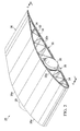
- the wing 25 may comprise a deformable tubular member such as a tubular wing spar 28 attached by joints 39 to each of a plurality of substantially non-deformable structures, such as spaced apart ribs 30.
- Each of the ribs 30 may be stiffened by struts 32 arranged in a truss pattern between upper and lower chords 30a, 30b respectively, of the rib 30, and the wing 25 may be stiffened in its span-wise direction by plurality of stringers 34.
- the wing 25 further includes an upper wing skin 36 which may comprise a plurality of lightweight panels 36a covering the stringers 34 and the ribs 30.
- the wing skin panels 36a may comprise a lightweight foam, and the ribs 30, struts 32, and stringers 34 may each comprise a fiber reinforced polymer such as a carbon fiber epoxy laminate.
- the wing 25 may include a lower wing skin 52 comprising, for example and without limitation, a thin flexible film membrane. Other types of wing skins are possible.
- the tubular spar 28 may be fabricated from a fiber reinforced polymer laminate using an unsymmetric laminate construction. This unsymmetrical laminate construction may result in interlaminar stresses that warp the tubular spar 28 into an ovoidal cross sectional shape when unpressurized or at low pressures, as will be discussed later in more detail. Additional details of a typical construction for the wing 25 are disclosed in US Patent Application Number 13/276,750 filed October 19, 2011 .
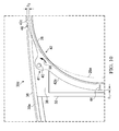
- each of the joints 39 broadly comprises a ring 42 surrounding the tubular spar 28, and a plurality of pivot pins 40 strategically located around the circumference of the tubular spar 28.
- the ring 42 is compliant to the tubular spar 28.
- the pivot pins 40 pivotally connect the ring 42 to the rib 30, respectively at points of inflection 41.
- the points of inflection 41 are the points or locations along the curvature of the tubular spar 28 where the curvature of the tubular spar 28 changes during its deformation due to internal pressure changes. Locating the pivot pins 40 at the inflection points 41 may substantially eliminate induced radial deflection into the rib 30.
- Each of the pivot pins 40 may comprise, without limitation, a bolt and nut (not shown) assembled to allow free rotational movement of the ring 42 relative to the rib 30.
- the pivot pins 40 along with the compliancy of the ring 42 allow the ring 42 to deform without transmitting substantial stress from the tubular spar 28 to the rib 30.
- the pivot pins 40 connect the ring 42 to webs 38 forming part of the rib 30.
- the upper chord 30a ( FIGS. 4 , 5 and 7 ) of the rib 30 includes a rib opening 43 therein for purposes which will become later apparent.
- the ring 42 conformally engages and extends around the circumference of the spar 28, and functions to attach and support rib 30 on the tubular spar 28, as well as stabilize the tubular spar 28.
- the ring 42 may be fabricated of a lightweight material such as a fiber reinforced polymer laminate that has a radial stiffness that is less than the radial stiffness of the rib 30.
- the ring 42 comprises first and second halves 42a, 42b that are joined together by splices 44. Upper and lower sections 42c, 42d respectively of the ring 42 may have a reduced thickness, as will be discussed below, or other characteristics or properties that allow these sections to more readily flex and deform along with the deformation of the tubular spar 28.
- the forward section 45 ( FIG. 5 ) of the ring 42 is pivotally attached to a forward portion 30c of the rib 30 by a first pair 40a of the pivot pins 40 ( FIG. 6 ).
- a rear section 47 of the ring 42 is pivotally attached to a rear portion 30d of the rib 30 by a second pair 40b of the pivot pins 40. It should be noted here that while a two-piece ring construction has been disclosed in the illustrated example, in other embodiments, the ring 42 may comprise more than two pieces or may be of a one-piece construction.
- the ring 42 may have a substantially U-shaped cross section 51 around its entire circumference.
- the forward and aft sections 45, 47 ( FIG. 6 ) of the ring 42 have a substantially U-shaped cross section 51 (see FIG. 8A ), and the upper and lower sections 42c, 42d have a strap-like construction possessing a substantially flat cross sectional shape 53 (see FIG. 8B ).
- the ring 42 is loaded radially inwardly against the tubular spar 28 around its entire circumference by tensioning the ring 42.
- Tensioning of the ring 42 may be achieved as it is being installed around the tubular spar 28, so that the ring 42 is preloaded against the tubular spar 28 following its installation.
- the ring 42 may be provided with a conventional tensioning device (not shown) which may be used after the ring 42 is installed to tension the ring 42 and compress it against the tubular spar 28.
- Other installation and tensioning methods are possible.
- the cross sectional shape of the tubular spar 28 may be substantially ovoid at the time it is manufactured, as well as throughout periods of relatively low internal pressure.
- the tubular spar 28 deforms to a substantially circular cross sectional shape when it is at or near full internal gas pressurization, however as gas is drawn from the tubular spar 28 for use in propelling the aircraft 20, the tubular spar 28 progressively deforms and springs back to its natural ovoidal cross sectional shape.
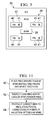
- FIG. 9 the cross sectional shape of the tubular spar 28 when substantially fully pressurized is shown in full line at 28, and its ovoidal cross sectional shape when substantially unpressurized is shown by the broken line 28a.
- the ring 42 flexes and substantially follows the deformation of the tubular spar 28, remaining conformed to and loaded against the tubular spar 28.
- the upper and lower sections 42c, 42d of the ring 42 deform substantially vertically along with the tubular spar 28 into upper and lower vertical gaps 48, 50, respectively, in the rib 30.
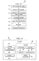
- a method of attaching a wing rib 30 to a tubular wing spar 28 begins at step 60 in which a ring 42 is placed around the tubular spar 28.
- this installation process may comprise installing two ring halves 42a, 42b around the tubular spar 28 and then splicing the two ring halves 42a, 42b together.
- the ring is radially loaded against the tubular spar 28. This loading step may be achieved by tensioning the ring 42 substantially concurrently during the ring installation process shown in step 60, or by tensioning the ring 42 after it has been installed around the tubular spar 28.
- the ring 42 is pivotally connected to the rib 30. Step 64 may be performed by pivotally connecting the ring 42 with the tubular spar 28 by locating pivot pins at the points of inflection 41.
- Embodiments of the disclosure may find use in a variety of potential applications, particularly in the transportation industry, including for example, aerospace, marine, automotive applications and other applications that employ deformable structures such as deformable tanks or deformable tubular members that are used to support non-deformable structures.
- exemplary method 66 may include specification and design 70 of the aircraft 68 and material procurement 72.
- component and subassembly manufacturing 74 and system integration 76 of the aircraft 68 takes place.
- the aircraft 68 may go through certification and delivery 78 in order to be placed in service 80.
- routine maintenance and service 82 which may also include modification, reconfiguration, refurbishment, and so on.
- Each of the processes of method 66 may be performed or carried out by a system integrator, a third party, and/or an operator (e.g., a customer).
- a system integrator may include without limitation any number of aircraft manufacturers and major-system subcontractors
- a third party may include without limitation any number of vendors, subcontractors, and suppliers
- an operator may be an airline, leasing company, military entity, service organization, and so on.
- the aircraft 68 produced by exemplary method 66 may include an airframe 84 with a plurality of systems 86 and an interior 88.
- high-level systems 86 include one or more of a propulsion system 90, an electrical system 92, a hydraulic system 94, an environmental system 96, an energy generation system 98 such as solar energy panels (not shown) and/or fuel cells (not shown).
- Energy produced by the energy generation system 98 may be stored in energy storage tanks 100 forming part of the airframe 84.
- energy in gaseous or liquid form may be stored in the tubular spars 28 previously described. Any number of other systems may be included.
- an aerospace example is shown, certain of the principles of the disclosure may be applied to other industries.
- Systems and methods embodied herein may be employed during any one or more of the stages of the production and service method 66.
- components or subassemblies corresponding to production process 74 may be fabricated or manufactured in a manner similar to components or subassemblies produced while the aircraft 68 is in service.
- one or more apparatus embodiments, method embodiments, or a combination thereof may be utilized during the production stages 74 and 76, for example, by substantially expediting assembly of or reducing the cost of an aircraft 68.
- apparatus embodiments, method embodiments, or a combination thereof may be utilized while the aircraft 68 is in service, for example and without limitation, to maintenance and service 82.
- an aircraft wing includes a rib attached by a joint to a tubular spar that varies in cross sectional shape during flight.
- the joint includes a ring attached to the tubular spar, and pivot pins connecting the ring with the rib.
- the pivot pins allow relative movement between the rib and the tubular spar as the tubular spar varies in cross sectional shape.
Landscapes
- Engineering & Computer Science (AREA)
- Mechanical Engineering (AREA)
- Aviation & Aerospace Engineering (AREA)
- Moulding By Coating Moulds (AREA)
- Mutual Connection Of Rods And Tubes (AREA)
Applications Claiming Priority (1)
| Application Number | Priority Date | Filing Date | Title |
|---|---|---|---|
| US13/419,791 US9346533B2 (en) | 2011-10-19 | 2012-03-14 | Attachment of aircraft ribs to spars having variable geometry |
Publications (3)
| Publication Number | Publication Date |
|---|---|
| EP2639152A2 true EP2639152A2 (de) | 2013-09-18 |
| EP2639152A3 EP2639152A3 (de) | 2014-08-13 |
| EP2639152B1 EP2639152B1 (de) | 2017-08-09 |
Family
ID=47681771
Family Applications (1)
| Application Number | Title | Priority Date | Filing Date |
|---|---|---|---|
| EP13154386.0A Active EP2639152B1 (de) | 2012-03-14 | 2013-02-07 | Anbringung von flugzeugrippen an holme mit variabler geometrie |
Country Status (3)
| Country | Link |
|---|---|
| US (1) | US9346533B2 (de) |
| EP (1) | EP2639152B1 (de) |
| ES (1) | ES2646587T3 (de) |
Cited By (7)
| Publication number | Priority date | Publication date | Assignee | Title |
|---|---|---|---|---|
| CN104475952A (zh) * | 2014-11-05 | 2015-04-01 | 北京航星机器制造有限公司 | 对称式筋骨-蒙皮钣焊轻型金属结构的电阻焊方法 |
| CN109533278A (zh) * | 2018-12-04 | 2019-03-29 | 南京航空航天大学 | 可实现均匀伸缩变形的翼肋结构 |
| EP3798116A1 (de) * | 2019-09-25 | 2021-03-31 | Formtech Composites Ltd. | Flügelholm |
| FR3111590A1 (fr) * | 2020-06-23 | 2021-12-24 | Dassault Aviation | Reservoir de gaz destine a servir d'element structurel au fuselage, a l'empennage ou a la voilure d'un aeronef |
| US20220266980A1 (en) * | 2021-02-25 | 2022-08-25 | Airbus Operations Limited | Wingbox with fuel tank attached to ribs |
| US11434014B2 (en) * | 2018-10-10 | 2022-09-06 | Imagine Aero Inc. | Aircraft spars with integrated power cells, and associated systems and methods |
| EP4056478A1 (de) * | 2021-03-09 | 2022-09-14 | Airbus Operations GmbH | Strömungskörper für ein luftfahrzeug mit integriertem gastank |
Families Citing this family (10)
| Publication number | Priority date | Publication date | Assignee | Title |
|---|---|---|---|---|
| US9156559B2 (en) | 2011-10-19 | 2015-10-13 | The Boeing Company | Segmented aircraft wing having solar arrays |
| US9346533B2 (en) * | 2011-10-19 | 2016-05-24 | The Boeing Company | Attachment of aircraft ribs to spars having variable geometry |
| JP6238168B2 (ja) * | 2014-02-04 | 2017-11-29 | 三菱重工業株式会社 | 複合材構造 |
| US10000274B2 (en) * | 2015-08-20 | 2018-06-19 | The Boeing Company | Mitigation of surface discontinuities between flight control surfaces and an airframe of an aircraft |
| US10457391B2 (en) * | 2016-03-15 | 2019-10-29 | Selex Galileo Inc. | Method and system for a small unmanned aerial system for delivering electronic warfare and cyber effects |
| US10286998B2 (en) * | 2016-05-05 | 2019-05-14 | The Boeing Company | Mechanical fastening system and associated structural assembly and method |
| US20180118327A1 (en) * | 2016-10-26 | 2018-05-03 | Kamron Blevins | Aircraft wing rotatable about a spar |
| EP4100320A4 (de) | 2020-02-04 | 2024-02-14 | AeroVironment, Inc. | Rippenmontageflansche für ein unbemanntes luftfahrzeug |
| CN113639592B (zh) * | 2021-08-27 | 2023-04-18 | 西安近代化学研究所 | 一种适用于宽速域的跨音速导弹弹翼 |
| CN113733595B (zh) * | 2021-08-30 | 2022-06-14 | 北京航空航天大学 | 一种全包裹式复合材料泡沫夹芯翼肋加工方法 |
Family Cites Families (23)
| Publication number | Priority date | Publication date | Assignee | Title |
|---|---|---|---|---|
| US1343707A (en) | 1918-11-25 | 1920-06-15 | Edmund B Carns | Aircraft |
| US1548403A (en) | 1923-11-21 | 1925-08-04 | Armstrong Siddeley Motors Ltd | Wing or the like for aircraft |
| US1760386A (en) | 1926-05-06 | 1930-05-27 | John Dumans Van Vliet | Flying machine |
| US1765791A (en) * | 1927-01-29 | 1930-06-24 | Fokker Aircraft Corp | Method and means for constructing airplane wings, fuselages, and other structures |
| US2400649A (en) * | 1942-02-27 | 1946-05-21 | Autogiro Co Of America | Molded airfoil, especially for sustaining rotors |
| US2749061A (en) | 1954-06-18 | 1956-06-05 | Wesley A Franz | Airplane wing stress compensating structure assembly |
| US3013614A (en) * | 1956-03-14 | 1961-12-19 | Haviland H Platt | Rotor blade |
| US2981337A (en) * | 1959-09-08 | 1961-04-25 | Hiller Aircraft Corp | Propeller blade |
| US3756541A (en) * | 1971-01-25 | 1973-09-04 | P Orazi | Aircraft |
| US4577815A (en) | 1979-11-26 | 1986-03-25 | Paul Orazi | Wing assemblies for aircraft |
| US4739954A (en) | 1986-12-29 | 1988-04-26 | Hamilton Terry W | Over-lap rib joint |
| US5984230A (en) | 1997-12-15 | 1999-11-16 | Orazi; Paul | Wing assemblies for aircraft |
| US7802756B2 (en) | 2000-02-14 | 2010-09-28 | Aerovironment Inc. | Aircraft control system |
| DE10055961B4 (de) * | 2000-11-11 | 2004-09-09 | Eads Deutschland Gmbh | Variabler Flügelbereich mit einstellbarer, sich in Spannweiten-Richtung erstreckender Profilform |
| US20050116086A1 (en) | 2003-11-12 | 2005-06-02 | Paul Orazi | Wing assemblies for aircraft |
| US20060145030A1 (en) | 2004-12-07 | 2006-07-06 | Cowan David L | Deformation-control system and method |
| US7762500B1 (en) | 2006-11-06 | 2010-07-27 | Sanjay Dhall | Telescopic wing with articulated structural spar |
| WO2009036465A1 (en) | 2007-09-14 | 2009-03-19 | Aurora Flight Sciences Corporation | Non-planar adaptive wing solar aircraft |
| US8128025B2 (en) | 2008-03-21 | 2012-03-06 | The Boeing Company | Providing skins for aircraft fuselages |
| DE102008020390A1 (de) | 2008-04-23 | 2009-11-05 | Airbus Deutschland Gmbh | Tragflügel für ein Luftfahrzeug |
| US8382045B2 (en) | 2009-07-21 | 2013-02-26 | The Boeing Company | Shape-changing control surface |
| US9156559B2 (en) * | 2011-10-19 | 2015-10-13 | The Boeing Company | Segmented aircraft wing having solar arrays |
| US9346533B2 (en) * | 2011-10-19 | 2016-05-24 | The Boeing Company | Attachment of aircraft ribs to spars having variable geometry |
-
2012
- 2012-03-14 US US13/419,791 patent/US9346533B2/en active Active
-
2013
- 2013-02-07 EP EP13154386.0A patent/EP2639152B1/de active Active
- 2013-02-07 ES ES13154386.0T patent/ES2646587T3/es active Active
Cited By (12)
| Publication number | Priority date | Publication date | Assignee | Title |
|---|---|---|---|---|
| CN104475952A (zh) * | 2014-11-05 | 2015-04-01 | 北京航星机器制造有限公司 | 对称式筋骨-蒙皮钣焊轻型金属结构的电阻焊方法 |
| CN104475952B (zh) * | 2014-11-05 | 2019-01-01 | 北京航星机器制造有限公司 | 对称式筋骨-蒙皮钣焊轻型金属结构的电阻焊方法 |
| US11434014B2 (en) * | 2018-10-10 | 2022-09-06 | Imagine Aero Inc. | Aircraft spars with integrated power cells, and associated systems and methods |
| CN109533278A (zh) * | 2018-12-04 | 2019-03-29 | 南京航空航天大学 | 可实现均匀伸缩变形的翼肋结构 |
| CN109533278B (zh) * | 2018-12-04 | 2024-03-19 | 南京航空航天大学 | 可实现均匀伸缩变形的翼肋结构 |
| EP3798116A1 (de) * | 2019-09-25 | 2021-03-31 | Formtech Composites Ltd. | Flügelholm |
| FR3111590A1 (fr) * | 2020-06-23 | 2021-12-24 | Dassault Aviation | Reservoir de gaz destine a servir d'element structurel au fuselage, a l'empennage ou a la voilure d'un aeronef |
| US20220266980A1 (en) * | 2021-02-25 | 2022-08-25 | Airbus Operations Limited | Wingbox with fuel tank attached to ribs |
| US12145739B2 (en) * | 2021-02-25 | 2024-11-19 | Airbus Operations Limited | Wingbox with fuel tank attached to ribs |
| EP4056478A1 (de) * | 2021-03-09 | 2022-09-14 | Airbus Operations GmbH | Strömungskörper für ein luftfahrzeug mit integriertem gastank |
| DE102021105609A1 (de) | 2021-03-09 | 2022-09-15 | Airbus Operations Gmbh | Strömungskörper für ein Luftfahrzeug mit integriertem Gastank |
| US11945599B2 (en) | 2021-03-09 | 2024-04-02 | Airbus Operations Gmbh | Flow body for an aircraft with integrated gas tank |
Also Published As
| Publication number | Publication date |
|---|---|
| EP2639152A3 (de) | 2014-08-13 |
| EP2639152B1 (de) | 2017-08-09 |
| ES2646587T3 (es) | 2017-12-14 |
| US20130240671A1 (en) | 2013-09-19 |
| US9346533B2 (en) | 2016-05-24 |
Similar Documents
| Publication | Publication Date | Title |
|---|---|---|
| EP2639152B1 (de) | Anbringung von flugzeugrippen an holme mit variabler geometrie | |
| US10640221B2 (en) | Wing airfoil stiffening for solar powered aircraft | |
| Thill et al. | Morphing skins | |
| Ramrakhyani et al. | Aircraft structural morphing using tendon-actuated compliant cellular trusses | |
| Airoldi et al. | Chiral topologies for composite morphing structures–Part I: Development of a chiral rib for deformable airfoils | |
| US8973871B2 (en) | Box structures for carrying loads and methods of making the same | |
| US7185851B2 (en) | Inflatable aerodynamic wing and method | |
| CN104229117B (zh) | 自平衡压力隔板 | |
| US8720822B2 (en) | Wing load alleviation structure | |
| Kudva et al. | Overview of the DARPA/AFRL/NASA smart wing phase II program | |
| US9365285B2 (en) | Propeller blade with reinforcing spars and boxes, and propeller comprising at least one such blade | |
| US8957303B2 (en) | Strain isolation layer assemblies and methods | |
| EP3309060B1 (de) | Aufblasbarer propeller | |
| EP3760534B1 (de) | Druckgefäss mit einer im wesentlichen flachen platte | |
| Romeo et al. | HELIPLAT: Aerodynamic and Structural Analysis of HAVE Solar Powered Platform. | |
| US20240278901A1 (en) | Variable Radius Assembly and Method of Using the Same | |
| US10065731B2 (en) | Vibration-harvesting, variable-stiffness system and method | |
| GB2604141A (en) | Aircraft wing with tubular fuel tanks | |
| KR101219172B1 (ko) | 무인항공기 및 무인항공기 날개의 인장을 통한 굽힘 강성을 증대시키는 방법 | |
| Straubel et al. | Design and sizing of the GOSSAMER boom deployment concept | |
| Li et al. | Propagating Instability in Deployable Propeller Blade Structures | |
| Castillo-Acero et al. | Morphing structure for a rudder | |
| Turnock et al. | Morphing of ‘flying’shapes for autonomous underwater and aerial vehicles | |
| Martin et al. | Smart wing wind tunnel model design | |
| McNamara et al. | Pressure Maintenance of High-Altitude Inflatable Kite Systems |
Legal Events
| Date | Code | Title | Description |
|---|---|---|---|
| PUAI | Public reference made under article 153(3) epc to a published international application that has entered the european phase |
Free format text: ORIGINAL CODE: 0009012 |
|
| AK | Designated contracting states |
Kind code of ref document: A2 Designated state(s): AL AT BE BG CH CY CZ DE DK EE ES FI FR GB GR HR HU IE IS IT LI LT LU LV MC MK MT NL NO PL PT RO RS SE SI SK SM TR |
|
| AX | Request for extension of the european patent |
Extension state: BA ME |
|
| PUAL | Search report despatched |
Free format text: ORIGINAL CODE: 0009013 |
|
| AK | Designated contracting states |
Kind code of ref document: A3 Designated state(s): AL AT BE BG CH CY CZ DE DK EE ES FI FR GB GR HR HU IE IS IT LI LT LU LV MC MK MT NL NO PL PT RO RS SE SI SK SM TR |
|
| AX | Request for extension of the european patent |
Extension state: BA ME |
|
| RIC1 | Information provided on ipc code assigned before grant |
Ipc: B64C 3/18 20060101AFI20140708BHEP Ipc: B64C 3/34 20060101ALI20140708BHEP |
|
| 17P | Request for examination filed |
Effective date: 20150213 |
|
| RBV | Designated contracting states (corrected) |
Designated state(s): AL AT BE BG CH CY CZ DE DK EE ES FI FR GB GR HR HU IE IS IT LI LT LU LV MC MK MT NL NO PL PT RO RS SE SI SK SM TR |
|
| GRAP | Despatch of communication of intention to grant a patent |
Free format text: ORIGINAL CODE: EPIDOSNIGR1 |
|
| RIN1 | Information on inventor provided before grant (corrected) |
Inventor name: KRUSE, JOHN SCOTT Inventor name: FOGARTY, JOHN HERSHEY |
|
| INTG | Intention to grant announced |
Effective date: 20170221 |
|
| GRAS | Grant fee paid |
Free format text: ORIGINAL CODE: EPIDOSNIGR3 |
|
| GRAA | (expected) grant |
Free format text: ORIGINAL CODE: 0009210 |
|
| AK | Designated contracting states |
Kind code of ref document: B1 Designated state(s): AL AT BE BG CH CY CZ DE DK EE ES FI FR GB GR HR HU IE IS IT LI LT LU LV MC MK MT NL NO PL PT RO RS SE SI SK SM TR |
|
| REG | Reference to a national code |
Ref country code: GB Ref legal event code: FG4D |
|
| REG | Reference to a national code |
Ref country code: CH Ref legal event code: EP Ref country code: AT Ref legal event code: REF Ref document number: 916490 Country of ref document: AT Kind code of ref document: T Effective date: 20170815 |
|
| REG | Reference to a national code |
Ref country code: IE Ref legal event code: FG4D |
|
| REG | Reference to a national code |
Ref country code: DE Ref legal event code: R096 Ref document number: 602013024624 Country of ref document: DE |
|
| REG | Reference to a national code |
Ref country code: NL Ref legal event code: MP Effective date: 20170809 |
|
| REG | Reference to a national code |
Ref country code: ES Ref legal event code: FG2A Ref document number: 2646587 Country of ref document: ES Kind code of ref document: T3 Effective date: 20171214 |
|
| REG | Reference to a national code |
Ref country code: LT Ref legal event code: MG4D |
|
| REG | Reference to a national code |
Ref country code: AT Ref legal event code: MK05 Ref document number: 916490 Country of ref document: AT Kind code of ref document: T Effective date: 20170809 |
|
| PG25 | Lapsed in a contracting state [announced via postgrant information from national office to epo] |
Ref country code: FI Free format text: LAPSE BECAUSE OF FAILURE TO SUBMIT A TRANSLATION OF THE DESCRIPTION OR TO PAY THE FEE WITHIN THE PRESCRIBED TIME-LIMIT Effective date: 20170809 Ref country code: SE Free format text: LAPSE BECAUSE OF FAILURE TO SUBMIT A TRANSLATION OF THE DESCRIPTION OR TO PAY THE FEE WITHIN THE PRESCRIBED TIME-LIMIT Effective date: 20170809 Ref country code: NO Free format text: LAPSE BECAUSE OF FAILURE TO SUBMIT A TRANSLATION OF THE DESCRIPTION OR TO PAY THE FEE WITHIN THE PRESCRIBED TIME-LIMIT Effective date: 20171109 Ref country code: AT Free format text: LAPSE BECAUSE OF FAILURE TO SUBMIT A TRANSLATION OF THE DESCRIPTION OR TO PAY THE FEE WITHIN THE PRESCRIBED TIME-LIMIT Effective date: 20170809 Ref country code: HR Free format text: LAPSE BECAUSE OF FAILURE TO SUBMIT A TRANSLATION OF THE DESCRIPTION OR TO PAY THE FEE WITHIN THE PRESCRIBED TIME-LIMIT Effective date: 20170809 Ref country code: LT Free format text: LAPSE BECAUSE OF FAILURE TO SUBMIT A TRANSLATION OF THE DESCRIPTION OR TO PAY THE FEE WITHIN THE PRESCRIBED TIME-LIMIT Effective date: 20170809 Ref country code: NL Free format text: LAPSE BECAUSE OF FAILURE TO SUBMIT A TRANSLATION OF THE DESCRIPTION OR TO PAY THE FEE WITHIN THE PRESCRIBED TIME-LIMIT Effective date: 20170809 |
|
| REG | Reference to a national code |
Ref country code: FR Ref legal event code: PLFP Year of fee payment: 6 |
|
| PG25 | Lapsed in a contracting state [announced via postgrant information from national office to epo] |
Ref country code: PL Free format text: LAPSE BECAUSE OF FAILURE TO SUBMIT A TRANSLATION OF THE DESCRIPTION OR TO PAY THE FEE WITHIN THE PRESCRIBED TIME-LIMIT Effective date: 20170809 Ref country code: IS Free format text: LAPSE BECAUSE OF FAILURE TO SUBMIT A TRANSLATION OF THE DESCRIPTION OR TO PAY THE FEE WITHIN THE PRESCRIBED TIME-LIMIT Effective date: 20171209 Ref country code: GR Free format text: LAPSE BECAUSE OF FAILURE TO SUBMIT A TRANSLATION OF THE DESCRIPTION OR TO PAY THE FEE WITHIN THE PRESCRIBED TIME-LIMIT Effective date: 20171110 Ref country code: RS Free format text: LAPSE BECAUSE OF FAILURE TO SUBMIT A TRANSLATION OF THE DESCRIPTION OR TO PAY THE FEE WITHIN THE PRESCRIBED TIME-LIMIT Effective date: 20170809 Ref country code: BG Free format text: LAPSE BECAUSE OF FAILURE TO SUBMIT A TRANSLATION OF THE DESCRIPTION OR TO PAY THE FEE WITHIN THE PRESCRIBED TIME-LIMIT Effective date: 20171109 Ref country code: LV Free format text: LAPSE BECAUSE OF FAILURE TO SUBMIT A TRANSLATION OF THE DESCRIPTION OR TO PAY THE FEE WITHIN THE PRESCRIBED TIME-LIMIT Effective date: 20170809 |
|
| PG25 | Lapsed in a contracting state [announced via postgrant information from national office to epo] |
Ref country code: DK Free format text: LAPSE BECAUSE OF FAILURE TO SUBMIT A TRANSLATION OF THE DESCRIPTION OR TO PAY THE FEE WITHIN THE PRESCRIBED TIME-LIMIT Effective date: 20170809 Ref country code: RO Free format text: LAPSE BECAUSE OF FAILURE TO SUBMIT A TRANSLATION OF THE DESCRIPTION OR TO PAY THE FEE WITHIN THE PRESCRIBED TIME-LIMIT Effective date: 20170809 Ref country code: CZ Free format text: LAPSE BECAUSE OF FAILURE TO SUBMIT A TRANSLATION OF THE DESCRIPTION OR TO PAY THE FEE WITHIN THE PRESCRIBED TIME-LIMIT Effective date: 20170809 |
|
| REG | Reference to a national code |
Ref country code: DE Ref legal event code: R097 Ref document number: 602013024624 Country of ref document: DE |
|
| PG25 | Lapsed in a contracting state [announced via postgrant information from national office to epo] |
Ref country code: SK Free format text: LAPSE BECAUSE OF FAILURE TO SUBMIT A TRANSLATION OF THE DESCRIPTION OR TO PAY THE FEE WITHIN THE PRESCRIBED TIME-LIMIT Effective date: 20170809 Ref country code: SM Free format text: LAPSE BECAUSE OF FAILURE TO SUBMIT A TRANSLATION OF THE DESCRIPTION OR TO PAY THE FEE WITHIN THE PRESCRIBED TIME-LIMIT Effective date: 20170809 Ref country code: EE Free format text: LAPSE BECAUSE OF FAILURE TO SUBMIT A TRANSLATION OF THE DESCRIPTION OR TO PAY THE FEE WITHIN THE PRESCRIBED TIME-LIMIT Effective date: 20170809 |
|
| PLBE | No opposition filed within time limit |
Free format text: ORIGINAL CODE: 0009261 |
|
| STAA | Information on the status of an ep patent application or granted ep patent |
Free format text: STATUS: NO OPPOSITION FILED WITHIN TIME LIMIT |
|
| 26N | No opposition filed |
Effective date: 20180511 |
|
| PG25 | Lapsed in a contracting state [announced via postgrant information from national office to epo] |
Ref country code: SI Free format text: LAPSE BECAUSE OF FAILURE TO SUBMIT A TRANSLATION OF THE DESCRIPTION OR TO PAY THE FEE WITHIN THE PRESCRIBED TIME-LIMIT Effective date: 20170809 |
|
| REG | Reference to a national code |
Ref country code: CH Ref legal event code: PL |
|
| PG25 | Lapsed in a contracting state [announced via postgrant information from national office to epo] |
Ref country code: MC Free format text: LAPSE BECAUSE OF FAILURE TO SUBMIT A TRANSLATION OF THE DESCRIPTION OR TO PAY THE FEE WITHIN THE PRESCRIBED TIME-LIMIT Effective date: 20170809 |
|
| REG | Reference to a national code |
Ref country code: IE Ref legal event code: MM4A |
|
| REG | Reference to a national code |
Ref country code: BE Ref legal event code: MM Effective date: 20180228 |
|
| PG25 | Lapsed in a contracting state [announced via postgrant information from national office to epo] |
Ref country code: LI Free format text: LAPSE BECAUSE OF NON-PAYMENT OF DUE FEES Effective date: 20180228 Ref country code: LU Free format text: LAPSE BECAUSE OF NON-PAYMENT OF DUE FEES Effective date: 20180207 Ref country code: CH Free format text: LAPSE BECAUSE OF NON-PAYMENT OF DUE FEES Effective date: 20180228 |
|
| PG25 | Lapsed in a contracting state [announced via postgrant information from national office to epo] |
Ref country code: IE Free format text: LAPSE BECAUSE OF NON-PAYMENT OF DUE FEES Effective date: 20180207 |
|
| PG25 | Lapsed in a contracting state [announced via postgrant information from national office to epo] |
Ref country code: BE Free format text: LAPSE BECAUSE OF NON-PAYMENT OF DUE FEES Effective date: 20180228 |
|
| PG25 | Lapsed in a contracting state [announced via postgrant information from national office to epo] |
Ref country code: MT Free format text: LAPSE BECAUSE OF NON-PAYMENT OF DUE FEES Effective date: 20180207 |
|
| PG25 | Lapsed in a contracting state [announced via postgrant information from national office to epo] |
Ref country code: TR Free format text: LAPSE BECAUSE OF FAILURE TO SUBMIT A TRANSLATION OF THE DESCRIPTION OR TO PAY THE FEE WITHIN THE PRESCRIBED TIME-LIMIT Effective date: 20170809 |
|
| PG25 | Lapsed in a contracting state [announced via postgrant information from national office to epo] |
Ref country code: HU Free format text: LAPSE BECAUSE OF FAILURE TO SUBMIT A TRANSLATION OF THE DESCRIPTION OR TO PAY THE FEE WITHIN THE PRESCRIBED TIME-LIMIT; INVALID AB INITIO Effective date: 20130207 Ref country code: PT Free format text: LAPSE BECAUSE OF FAILURE TO SUBMIT A TRANSLATION OF THE DESCRIPTION OR TO PAY THE FEE WITHIN THE PRESCRIBED TIME-LIMIT Effective date: 20170809 |
|
| PG25 | Lapsed in a contracting state [announced via postgrant information from national office to epo] |
Ref country code: MK Free format text: LAPSE BECAUSE OF NON-PAYMENT OF DUE FEES Effective date: 20170809 Ref country code: CY Free format text: LAPSE BECAUSE OF FAILURE TO SUBMIT A TRANSLATION OF THE DESCRIPTION OR TO PAY THE FEE WITHIN THE PRESCRIBED TIME-LIMIT Effective date: 20170809 |
|
| PG25 | Lapsed in a contracting state [announced via postgrant information from national office to epo] |
Ref country code: AL Free format text: LAPSE BECAUSE OF FAILURE TO SUBMIT A TRANSLATION OF THE DESCRIPTION OR TO PAY THE FEE WITHIN THE PRESCRIBED TIME-LIMIT Effective date: 20170809 |
|
| P01 | Opt-out of the competence of the unified patent court (upc) registered |
Effective date: 20230516 |
|
| PGFP | Annual fee paid to national office [announced via postgrant information from national office to epo] |
Ref country code: GB Payment date: 20260227 Year of fee payment: 14 |
|
| PGFP | Annual fee paid to national office [announced via postgrant information from national office to epo] |
Ref country code: ES Payment date: 20260302 Year of fee payment: 14 |
|
| PGFP | Annual fee paid to national office [announced via postgrant information from national office to epo] |
Ref country code: DE Payment date: 20260227 Year of fee payment: 14 |
|
| PGFP | Annual fee paid to national office [announced via postgrant information from national office to epo] |
Ref country code: IT Payment date: 20260219 Year of fee payment: 14 |
|
| PGFP | Annual fee paid to national office [announced via postgrant information from national office to epo] |
Ref country code: FR Payment date: 20260225 Year of fee payment: 14 |