EP2639159A2 - Système de montage de moteur pour aéronef - Google Patents
Système de montage de moteur pour aéronef Download PDFInfo
- Publication number
- EP2639159A2 EP2639159A2 EP13159748.6A EP13159748A EP2639159A2 EP 2639159 A2 EP2639159 A2 EP 2639159A2 EP 13159748 A EP13159748 A EP 13159748A EP 2639159 A2 EP2639159 A2 EP 2639159A2
- Authority
- EP
- European Patent Office
- Prior art keywords
- engine
- frame
- linking system
- support structure
- aircraft
- Prior art date
- Legal status (The legal status is an assumption and is not a legal conclusion. Google has not performed a legal analysis and makes no representation as to the accuracy of the status listed.)
- Granted
Links
Images


Classifications
-
- B—PERFORMING OPERATIONS; TRANSPORTING
- B64—AIRCRAFT; AVIATION; COSMONAUTICS
- B64D—EQUIPMENT FOR FITTING IN OR TO AIRCRAFT; FLIGHT SUITS; PARACHUTES; ARRANGEMENT OR MOUNTING OF POWER PLANTS OR PROPULSION TRANSMISSIONS IN AIRCRAFT
- B64D27/00—Arrangement or mounting of power plants in aircraft; Aircraft characterised by the type or position of power plants
- B64D27/40—Arrangements for mounting power plants in aircraft
- B64D27/404—Suspension arrangements specially adapted for supporting vertical loads
-
- B—PERFORMING OPERATIONS; TRANSPORTING
- B64—AIRCRAFT; AVIATION; COSMONAUTICS
- B64D—EQUIPMENT FOR FITTING IN OR TO AIRCRAFT; FLIGHT SUITS; PARACHUTES; ARRANGEMENT OR MOUNTING OF POWER PLANTS OR PROPULSION TRANSMISSIONS IN AIRCRAFT
- B64D27/00—Arrangement or mounting of power plants in aircraft; Aircraft characterised by the type or position of power plants
- B64D27/40—Arrangements for mounting power plants in aircraft
- B64D27/406—Suspension arrangements specially adapted for supporting thrust loads, e.g. thrust links
Definitions
- the present disclosure relates generally to aircraft and, in particular, to connecting aircraft parts. Still more particularly, the present disclosure relates to a method and apparatus for connecting an engine to an aircraft.
- Engines that provide propulsion for an aircraft may be attached to the wings of an aircraft.
- An engine that is attached to the wings of an aircraft may take the form of a turbofan.
- the turbofan may be a high-bypass turbofan.
- An engine pylon may be used.
- An engine pylon may include a rigid support structure that is connected to both the wing and the engine and a fairing that is used to cover this support structure.
- the support structure may be connected to the engine using a forward mounting system and an aft mounting system.
- the aft mounting system may be used to connect the support structure to an engine core case for the engine.
- the aft mounting system may be configured to carry side loads, vertical loads, and thrust loads.
- the forward mounting system may be used to connect the support structure to a fan case for the engine.
- the forward mounting system may be configured to carry side loads and vertical loads.
- the forward mounting system may be connected to a top portion of the fan case.
- the support structure may be mounted above the fan case of the engine higher than desired. Consequently, the engine may be mounted further away from the wing than desired.
- the configuration of the fairing used to cover the support structure may be larger than desired.
- This larger configuration for the fairing may result in a less than desired aerodynamic flow.
- the height of the fairing may be higher than desired and may reduce a level of aerodynamic performance. As a result, the fuel efficiency of the aircraft may be reduced.
- an apparatus may comprise a frame, a first linking system connected to the frame, and a second linking system connected to the frame.
- the frame may be configured to be connected to a support structure for an engine of an aircraft.
- the first linking system may be configured to be connected to a fan case in the engine.
- the second linking system may be configured to be connected to an engine core case in the engine.
- the apparatus may constitute a forward mounting system for the aircraft engine.
- the frame may be configured to be connected to a forward end of the support structure.
- the frame can further have an elongated shape and be configured to extend forward of the support structure.
- the frame of the apparatus may have a first end configured to be connected to the support structure for the aircraft engine and a second end configured to be connected to the first linking system.
- the first end of the frame may further be configured to be connected to the second linking system.
- a method for operating an engine may be present.
- the engine connected to a wing of an aircraft by a mounting system having a frame, a first linking system connected to the frame and a fan case in the engine, and a second linking system connected to the frame and an engine core case in the engine may be operated.
- a number of side loads may be carried using the first linking system.
- a second number of loads may be carried using the second linking system.
- an aircraft engine mounting system may comprise a frame, a first linking system connected to the frame, a second linking system connected to the frame, a bracket, a bar, and a number of brackets.
- the frame may be configured to be connected to a support structure in an engine pylon for an engine of an aircraft.
- the frame may have a first end configured to be connected to the support structure for the engine of the aircraft and a second end configured to be connected to a first linking system.
- the frame may have a height which is smaller than a height of the support structure.
- the frame may comprise a first connector section at the first end of the frame, a second connector section at the second end of the frame, and a number of elongate members extending from the first connector section to the second connector section.
- the first linking system may be configured to be connected to a fan case in the engine.
- the first linking system may comprise a fixed link and a floating link.
- the first linking system may further be configured to carry a number of side loads in a first direction that is substantially parallel to a pitch axis through the aircraft.
- the second linking system may be configured to be connected to an engine core case in the engine.
- the second linking system may include at least one substantially J-shaped link having an upper end configured to be connected to the support structure and a forward end configured to be connected to the engine core case.
- the second linking system may further be configured to carry a number of vertical loads in a second direction that is substantially parallel to a yaw axis through the aircraft.
- the bracket may be configured to connect the first linking system to the fan case.
- the bar may be configured to connect the second linking system to the frame.
- the number of brackets may be configured to connect the second linking system to the engine core case.
- the frame, the first linking system, and the second linking system may be comprised of a number of materials selected from one of titanium, steel, and a steel alloy.
- a method for operating an engine may be present.
- the engine connected to an engine pylon of a wing of an aircraft by a forward mounting system having a frame, a first linking system connected to the frame and a fan case in the engine, and a second linking system connected to the frame and an engine core case in the engine may be operated.
- the frame may have a first end configured to be connected to a support structure for the aircraft engine and a second end configured to be connected to the first linking system.
- the frame may comprise a first connector section at the first end, a second connector section at the second end, and a number of elongate members extending from the first connector section to the second connector section.
- a number of side loads may be carried using the first linking system.
- a bracket may connect the first linking system to the fan case.
- a number of vertical loads may be carried using the second linking system.
- a number of brackets may be configured to connect the second linking system to the engine core case.
- an apparatus comprising a frame configured to be connected to a support structure for an engine of an aircraft, a first linking system connected to the frame and configured to be connected to a fan case in the engine, and a second linking system connected to the frame and configured to be connected to an engine core case in the engine.
- the frame has a first end configured to be connected to the support structure for the engine of the aircraft and a second end configured to be connected to the first linking system.
- the apparatus further comprises a bracket configured to connect the first linking system to the fan case.
- the apparatus further comprises a bar configured to connect the second linking system to the frame.
- the apparatus further comprises a number of brackets configured to connect the second linking system to the engine core case.
- the first linking system comprises a number of links.
- the number of links comprises a fixed link and a floating link.
- the frame comprises a first connector section, a second connector section, and a number of elongate members extending from the first connector section to the second connector section.
- the frame, the first linking system, and the second linking system are comprised of a number of materials selected from one of titanium, steel, and a steel alloy.
- the frame, the first linking system, and the second linking system form a forward mounting system for connecting the support structure to the engine.
- the first linking system is configured to carry a number of side loads in a direction that is substantially perpendicular to an axis extending centrally through the fan case.
- a side load in the number of side loads is in a direction that is substantially parallel to a pitch axis through the aircraft.
- the second linking system is configured to carry a number of vertical loads in a direction that is substantially perpendicular to the axis extending centrally through the fan case.
- a vertical load in the number of vertical loads is in a direction that is substantially parallel to a yaw axis through the aircraft.
- a method for operating an engine comprises operating the engine connected to a wing of an aircraft by a mounting system having a frame, a first linking system connected to the frame and a fan case in the engine, and a second linking system connected to the frame and an engine core case in the engine, carrying a number of side loads using the first linking system, and carrying a number of vertical loads using the second linking system.
- the step of carrying the number of side loads using the first linking system comprises carrying the number of side loads using the first linking system and the frame, wherein the frame has a first end configured to be connected to a support structure for the engine and a second end configured to be connected to the first linking system.
- the step of carrying the number of side loads using the first linking system comprises carrying the number of side loads using the first linking system and the frame, wherein a bracket is configured to connect the first linking system to the fan case.
- the step of carrying the number of vertical loads using the second linking system comprises carrying the number of vertical loads using the second linking system, wherein a bar is configured to connect the second linking system to the frame.
- the step of carrying the number of vertical loads using the second linking system comprises carrying the number of vertical loads using the second linking system, wherein a number of brackets is configured to connect the second linking system to the engine core case.
- the first linking system comprises a fixed link and a floating link.
- the frame comprises a first connector section, a second connector section, and a number of elongate members extending from the first connector section to the second connector section.
- the method further comprises carrying a number of thrust loads using the second linking system.
- the mounting system is a forward mounting system configured to connect an engine pylon to the engine.
- the method further comprises reducing draft during operation of the engine using a fairing having a desired configuration, wherein the fairing is configured to cover the mounting system and a support structure connected to the engine by the mounting system.
- an aircraft engine mounting system comprising: a frame configured to be connected to a support structure in an engine pylon for an engine of an aircraft in which the frame has a first end configured to be connected to the support structure for the engine of the aircraft and a second end configured to be connected to a first linking system and in which the frame comprises a first connector section at the first end of the frame; a second connector section at the second end of the frame; and a number of elongate members extending from the first connector section to the second connector section, the first linking system connected to the frame and configured to be connected to a fan case in the engine in which the first linking system comprises a fixed link and a floating link and in which the first linking system is configured to carry a number of side loads in a first direction that is substantially parallel to a pitch axis through the aircraft, a second linking system connected to the frame and configured to be connected to an engine core case in the engine in which the second linking system is configured to carry a number of vertical loads in a second direction that
- a method for operating an engine comprising operating the engine connected to an engine pylon of a wing of an aircraft by a forward mounting system having a frame, a first linking system connected to the frame and a fan case in the engine, and a second linking system connected to the frame and an engine core case in the engine in which the frame has a first end configured to be connected to a support structure for the engine and a second end configured to be connected to the first linking system and in which the frame comprises a first connector section at the first end; a second connector section at the second end; and a number of elongate members extending from the first connector section to the second connector section, carrying a number of side loads using the first linking system in which a bracket connects the first linking system to the fan case, and carrying a number of vertical loads using the second linking system in which a number of brackets is configured to connect the second linking system to the engine core case.
- the invention provides an engine mounting system for an aircraft comprising a support structure, a forward mounting system and an aft mounting system.
- the support structure may have a forward end and an aft end.
- the forward end of the support structure may be located aft of a fan case of the engine.
- the aft mounting system may be configured to connect a portion of the support structure located aft of the first end to a core case of the engine.
- the forward mounting system may be configured to connect the first end of the support structure to both the fan case and the engine core case.
- the different illustrative embodiments recognize and take into account one or more different considerations.
- the different illustrative embodiments recognize and take into account that the configuration of the support structure of an engine pylon may result in an undesired configuration for a fairing of the engine pylon when the support structure is connected to a fan case using some currently available forward mounting systems.
- the different illustrative embodiments recognize and take into account that the support structure may be longer and taller than desired when a forward mounting system is used to connect a forward end of the support structure to the top of a fan case for an engine.
- the size of the fairing used to cover the support structure may also increase in an undesired manner.
- a smaller fairing may be capable of reducing drag more than a larger fairing. Reducing drag may increase the aerodynamic performance of the aircraft.
- the forward end of the support structure may be connected to the engine core case instead of the fan case. This type of connection may allow for the fairing to be smaller than when the engine pylon is connected to the fan case.
- the different illustrative embodiments recognize and take into account that connecting the forward end of the support structure to the engine core case may be undesirable when a pre-cooler is present.
- the support structure When the forward end of the support structure is connected to the engine core case, the support structure may be angled or curved toward the engine core case. The shape of the support structure may not provide sufficient space for a pre-cooler.
- the different illustrative embodiments recognize and take into account that it may be desirable to have a forward mounting system that is configured to connect a forward end of the support structure of an engine pylon to the fan case of an engine in a manner such that the support structure may have a desired shape and size.
- an aircraft system may comprise a frame, a first linking system, and a second linking system.
- the frame may have a first end associated with a support structure for an engine of an aircraft and a second end configured to be connected to a linking system associated with a fan case of an engine for the aircraft.
- the second linking system may have a first end associated with the frame and a second end configured to be connected to an engine core case in the engine.
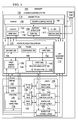
- aircraft 100 may include engine 102.
- Engine 102 may be implemented using a number of different types of engines.
- Engine 102 may be selected from one of, for example, without limitation, a rotary engine, a radial engine, a turboprop, a turbojet, a turbofan, a high-bypass turbofan, a low-bypass turbofan, an ultra-high bypass turbofan, and other suitable types of engines for use with aircraft 100.
- engine 102 may have housing 120.
- Housing 120 may be referred to as a "nacelle.”
- engine 102 may have fan case 116 and engine core case 118 located within housing 120 of engine 102.
- engine 102 may be connected to wing 104 on aircraft 100 using engine mounting system 106.
- engine mounting system 106 may include engine pylon 114, forward mounting system 110, and aft mounting system 112.
- Forward mounting system 110 and aft mounting system 112 may connect engine 102 to engine pylon 114, which may be connected to wing 104.
- a first component such as engine pylon 114
- a second component such as wing 104
- first component may be connected directly or indirectly to the second component.
- additional components may be present between the first component and the second component.
- the first component may be considered to be indirectly connected to the second component when one or more additional components may be present between the two components.
- no additional components are present between the two components.
- a first component may be connected to a second component in a number of different ways.
- a first component may be connected to a second component using a number of fasteners, an adhesive, or some other suitable mechanism for connecting components to each other.
- engine pylon 114 may include support structure 108 and fairing 109.
- Support structure 108 may have first end 115 and second end 117.
- First end 115 may be a forward end of support structure 108
- second end 117 may be an aft end of support structure 108.
- Second end 117 of support structure 108 may be connected to wing 104.
- Forward mounting system 110 and aft mounting system 112 may be connected to engine 102 and different portions of support structure 108.
- aft mounting system 112 may be configured to connect portion 119 of support structure 108 to engine core case 118 of engine 102.
- Portion 119 of support structure 108 may be located aft of first end 115 of support structure 108.
- portion 119 of support structure 108 may be second end 117 of support structure 108.
- forward mounting system 110 may comprise frame 124, first linking system 126, second linking system 128, and, in some cases, other suitable components.
- Frame 124, first linking system 126, and second linking system 128 may be comprised of a number of materials selected from at least one of titanium, steel, a steel alloy, and other suitable materials.
- Frame 124 may have first end 132 and second end 134.
- first end 132 of frame 124 may be connected to first end 115 of support structure 108.
- first end 132 of frame 124 may be connected to a location on support structure 108 proximate to first end 115 of support structure 108.
- First linking system 126 may be connected to second end 134 of frame 124 and fan case 116.
- Second linking system 128 may be connected to frame 124 and engine core case 118.
- second linking system 128 may be connected to first end 132 of frame 124.
- first end 136 of second linking system 128 may be connected to engine core case 118, while second end 138 of second linking system 128 may be connected to first end 132 of frame 124.
- forward mounting system 110 and aft mounting system 112 may be configured to carry loads 140.
- Loads 140 may include loads that result from support structure 108 being connected to engine 102.
- Carrying loads 140 may also be referred to as "reacting" loads in these illustrative examples.
- Forward mounting system 110 and aft mounting system 112 may carry loads 140.
- Loads 140 include number of side loads 141, number of vertical loads 142, and number of thrust loads 144.
- a "number of" means one or more items.
- number of side loads 141 may be one or more side loads.
- a “side load”, such as one of number of side loads 141, may be a load in a direction that is substantially parallel to pitch axis 146 through aircraft 100.
- a side load may be a load in a direction that is either inboard towards aircraft 100 or outboard away from aircraft 100.
- a "vertical load”, such as one of number of vertical loads 142, may be a load in a direction that is substantially parallel to yaw axis 148 through aircraft 100.
- a vertical load may be a load in a direction that is either up or down relative to aircraft 100.
- a thrust load such as one of number of thrust loads 144, may be a load in a direction that is substantially parallel to roll axis 150 through aircraft 100.
- a thrust load may be a load in a direction that is either towards a forward end of aircraft 100 or an aft end of aircraft 100.
- Aft mounting system 112 may be configured to carry number of side loads 141, number of vertical loads 142, and number of thrust loads 144.
- First linking system 126 of forward mounting system 110 may be configured to carry number of side loads 141.
- Second linking system 128 of forward mounting system 110 may be configured to carry number of vertical loads 142. In some cases, second linking system 128 may also be configured to carry number of thrust loads 144.
- forward mounting system 110 may also carry number of torque loads 152.
- a "torque load” may be a load in a direction around one of pitch axis 146, yaw axis 148, or roll axis 150.
- engine mounting system 106 may be configured to reduce and/or prevent movement of engine 102. More specifically, engine mounting system 106 may constrain movement of engine 102 with respect to six degrees of freedom when engine 102 is mounted to wing 104 using engine mounting system 106.
- the six degrees of freedom may include movement of engine 102 in a direction along pitch axis 146, yaw axis 148, and roll axis 150 and rotation of engine 102 about pitch axis 146, yaw axis 148, and roll axis 150.
- forward mounting system 110 may be configured such that length 122 and height 123 of support structure 108 may be reduced in accordance with an illustrative embodiment.
- first linking system 126 connected to fan case 116 may have a smaller size than a linking system configured to carry both number of side loads 141 and number of vertical loads 142.
- first linking system 126 may have a reduced height above fan case 116 as compared to a linking system configured to carry both number of side loads 141 and number of vertical loads 142. In this manner, height 123 of support structure 108 may be reduced. Further, frame 124 may connect first linking system 126 to support structure 108 in a manner that allows the height of support structure 108 above fan case 116 to be reduced.
- second linking system 128 may connect support structure 108 to engine core case 118 instead of to fan case 116.
- length 122 of support structure 108 may be reduced.
- support structure 108 may have length 122 that does not need to extend up to fan case 116.
- second linking system 128 may connect support structure 108 to engine core case 118 in a manner such that sufficient room may be present for a pre-cooler.
- frame 124 may have configuration 160 that allows for fairing 109 to cover at least one of support structure 108, forward mounting system 110, aft mounting system 112, and other suitable components.
- Configuration 160 may include, for example, without limitation, a shape, a size, a number of dimensions, and/or other suitable parameters for frame 124.
- fairing 109 may have desired configuration 164.
- desired configuration 164 may include a shape, a size, a number of dimensions, an aerodynamic property, and/or other suitable parameters for fairing 109.
- desired configuration 164 for fairing 109 may be a configuration that allows fairing 109 to provide a desired reduction in drag, while allowing engine 102 to be mounted closer to wing 104.
- one or more additional engines may be present in aircraft 100 in addition to engine 102 that may be mounted using a mounting system, such as engine mounting system 106.
- additional components such as fasteners, or other connecting mechanisms for connecting components, such as frame 124, first linking system 126, second linking system 128, and other suitable components in aircraft 100, may be present.
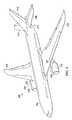
- aircraft 200 is an example of one implementation for aircraft 100 illustrated in block form in Figure 1 .
- aircraft 200 may have wing 202 and wing 204 attached to fuselage 206. Aircraft 200 also may include engine 208 attached to wing 202 and engine 210 attached to wing 204. As depicted, fuselage 206 may have tail section 212. Horizontal stabilizer 214, horizontal stabilizer 216, and vertical stabilizer 218 may be attached to tail section 212 of fuselage 206.
- engine 208 may be attached to wing 202 using engine mounting system 220.
- Engine 210 may be attached to wing 204 using engine mounting system 222.
- Engine mounting system 220 and engine mounting system 222 may be examples of one implementation for engine mounting system 106 in Figure 1 .
- engine mounting system 220 may include engine pylon 224, and engine mounting system 222 may include engine pylon 226.
- Engine pylon 224 and engine pylon 226 may be examples of one implementation for engine pylon 114 in Figure 1 .
- Engine mounting system 220 and engine mounting system 222 may be configured such that engine pylon 224 and engine pylon 226, respectively, have a reduced size that allows engine 208 and engine 210, respectively, to be attached closer to wing 202 and wing 204, respectively.
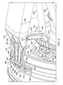
- FIG. 3 a partially-exposed side view of engine mounting system 222 for mounting engine 210 to wing 204 is depicted in accordance with an illustrative embodiment. As depicted, housing 300 for engine 210 is shown in phantom.
- fan case 302 and engine core case 304 may be seen within housing 300. As depicted, fan case 302 and engine core case 304 may be aligned with respect to axis 305. In other words, fan case 302 and engine core case 304 may be arranged such that axis 305 extends centrally through each of these components. In this manner, fan case 302 and engine core case 304 may be substantially concentric to each other.
- Engine mounting system 222 may be connected to both fan case 302 and engine core case 304.
- engine mounting system 222 may include engine pylon 226, forward mounting system 310, and aft mounting system 312.
- engine pylon 226 may be an example of one implementation for engine pylon 114 in Figure 1 .
- Forward mounting system 310 may be an example of one implementation for forward mounting system 110 in Figure 1 .
- Aft mounting system 312 may be an example of one implementation for aft mounting system 112 in Figure 1 .
- Engine pylon 226 may include support structure 306 and fairing 308.
- Support structure 306 may be an example of one implementation for support structure 108 in Figure 1 .
- Support structure 306 may have first end 314 and second end 316.
- First end 314 may be connected to wing 204.
- Fairing 308 may be an example of one implementation for fairing 109 in Figure 1 .
- forward mounting system 310 may be connected to second end 316 of support structure 306 or to a location on support structure 306 proximate to second end 316 of support structure 306. Forward mounting system 310 may be connected to support structure 306 closer to second end 316 of support structure 306 than to first end 314 of support structure 306. Aft mounting system 312 may be connected closer to first end 314 of support structure 306 than to second end 316 of support structure 306.
- Forward mounting system 310 may include frame 318, first linking system 320, and second linking system 322.
- Frame 318, first linking system 320, and second linking system 322 may be examples of implementations for frame 124, first linking system 126, and second linking system 128 in Figure 1 , respectively.
- frame 318 may have first end 324 and second end 326.
- First end 324 may be connected to support structure 306.
- Second end 326 may be connected to first linking system 320.
- first end 324 also may be connected to second linking system 322.
- support structure 334 may be an example of the support structure that may be used when a different type of forward mounting system (not shown) is used to connect support structure 334 only to fan case 302 and not to engine core case 304 in these illustrative examples.
- Support structure 334 has length 336, which may be longer than length 332.
- height 333 for support structure 306 may be shorter than height 337 of support structure 334.
- support structure 334 may extend above surface 338 of housing 300. As can be seen, support structure 334 may extend above fairing 308 in this illustrative example.
- fairing 308 may need to be increased in height and may have an undesired configuration (not shown). This undesired configuration may not provide desired aerodynamic properties for aircraft 200 in Figure 2 .
- support structure 306 When support structure 306 is used with forward mounting system 310, support structure 306 may not extend above surface 338 of housing 300. As a result, with the use of support structure 306 and forward mounting system 310, configuration 339 of fairing 308 may be more desirable. For example, without limitation, fairing 308 may have a smaller size, a more aerodynamic configuration, or both as compared to the use of support structure 334 without forward mounting system 310.
- frame 318 may allow support structure 306 to have length 332, which is less than length 336 for support structure 306. With length 332, support structure 306 may not extend above surface 338 of housing 300 for engine 210.
- frame 318 may have height 340 and length 341. A reduction of height 340, as compared to height 342 for support structure 306, may be depicted in this illustrative example.
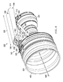
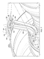
- FIG. 4 an illustration of an isometric view of an engine mounting system for connecting an engine to a wing is depicted in accordance with an illustrative embodiment.
- a view of front end 400 of fan case 302 is seen with first linking system 320 connected to frame 318.
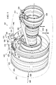
- FIG. 5 an illustration of an isometric view of an engine mounting system for connecting an engine to a wing showing load vectors is depicted in accordance with an illustrative embodiment.
- loads 500 are illustrated.
- Loads 500 may be an example of loads 144 in Figure 1 .
- loads 500 may include vertical load 506, thrust load 508, side load 502, side load 504, vertical load 510, and vertical load 512.
- Vertical load 506 may be generated by the weight of engine 210.
- Thrust load 508 may occur in response to operation of engine 210.
- Side load 502 and side load 504 may be reaction loads in these illustrative examples. As depicted, side load 502 and side load 504 may be carried by at least one of first linking system 320 and frame 318. These loads may be transferred by first linking system 320 and frame 318 to support structure 306. In these illustrative examples, number of elongate members 509 in frame 318 may carry side load 502 and side load 504 but not vertical load 510 and vertical load 512.
- vertical load 510 and vertical load 512 may be carried by second linking system 322 and frame 318.
- Vertical load 510 and vertical load 512 may be carried at first end 324 of frame 318 and not by number of elongate members 509.
- Vertical load 510 and vertical load 512 may be transferred to support structure 306 in these illustrative examples.
- other loads may be present that may be carried and transferred by forward mounting system 310, aft mounting system 312, or a combination of the two.
- height 340 for frame 318 may be smaller than height 342 for support structure 306, because first linking system 320 and frame 318 may be used to carry only side load 502 and side load 504 and not vertical load 510 and vertical load 512.
- vertical load 510 and vertical load 512 may be carried by second linking system 322.
- height 340 of frame 318 may be reduced as compared to height 342 of support structure 306.
- Support structure 306, in this illustrative example, may carry side load 502, side load 504, vertical load 510, and vertical load 512.
- side load 502 and side load 504 may be loads in a direction substantially parallel to axis 514.
- Axis 514 may be substantially perpendicular to axis 305 extending centrally through fan case 302 and engine core case 304.
- vertical load 510 and vertical load 512 may be in a direction substantially parallel to axis 516.
- Axis 516 may be substantially perpendicular to axis 305 and may be substantially perpendicular to axis 514.
- FIG. 6 a more-detailed illustration of a portion of a forward mounting system connected to a mounting structure and a fan case may be depicted in accordance with an illustrative embodiment.
- second end 326 of frame 318 may be connected to number of links 600 in first linking system 320.
- number of links 600 may comprise link 601 and link 602.
- link 601 may be fixed link 604, while link 602 may be floating link 606.
- fixed link 604 may be connected to second end 326 of frame 318 by fastener 608.
- Fixed link 604 may be connected to bracket 610 by fastener 612.
- Floating link 606 may be connected to second end 326 of frame 318 by fastener 614.
- Floating link 606 also may be connected to bracket 610 by fastener 616.
- fastener 616 may have a smaller size than fastener 612. By using a smaller size for fastener 616, floating link 606 may be moveable. In particular, floating link 606 may be loosely connected to second end 326 of frame 318 using fastener 616 such that this portion of floating link 606 does not carry loads during normal operation. Fastener 616 may be used to provide a loose connection such that this connection may function as a backup connection for floating link 606 and frame 318.
- second linking system 330 may include number of links 617.
- Number of links 617 may comprise link 618 and link 620 in these illustrative examples.
- Link 618 may be connected to frame 318 (connection not shown) and engine core case 304.
- connection to engine core case 304 may be made indirectly through a connection to bracket 622.
- link 618 may be connected to bracket 626 by fastener 628.
- link 620 also may be connected to engine core case 304 indirectly through bracket 622.
- link 620 may be connected to bracket 622 through fastener 624 in these illustrative examples.
- link 618 and link 620 may be connected to first end 324 of frame 318.
- This connection may be an indirect connection through bar 700.
- link 618 may be connected to bar 700 through fastener 702.
- Link 620 may be connected to bar 700 using fastener 704.
- Bar 700 may be connected to first end 324 of frame 318 using fastener 706.
- bracket 610 may have curved shape 800 that may be configured to substantially conform to the surface of fan case 302 (not shown).
- bracket 610 may be connected to fan case 302 in a number of different ways.
- bracket 610 may be connected to fan case 302 using adhesive, welds, fasteners, and other suitable mechanisms.
- bracket 610 may be formed as part of fan case 302.
- bracket 610 may include clevis 801.
- Clevis 801 may be configured to be connected to fixed link 604 in Figure 6 .
- clevis 801 may include flange 802 and flange 804.
- Flange 802 may have hole 806, and flange 804 may have hole 808.
- bracket 610 also may have clevis 809 that is configured to be connected to floating link 606 in Figure 6 .
- clevis 809 may comprise flange 810 and flange 812. These flanges may be configured to receive floating link 606.
- flange 810 may have hole 814
- flange 812 may have hole 816. Hole 814 and hole 816 may be configured to receive fastener 614 in Figure 6 .
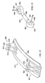
- FIG. 9 an illustration of a link in a first linking system is depicted in accordance with an illustrative embodiment.
- a more-detailed view of fixed link 604 is depicted.
- fixed link 604 may be elongate member 900 having first end 901 and second end 902.
- Connector 903 at first end 901 may be configured to be connected to second end 326 of frame 318 in Figure 3 .
- Connector 904 at second end 902 may be configured to be connected to flange 802 and flange 804 on bracket 610 in Figure 8 .
- connector 903 may have hole 905, and connector 904 may have hole 906.
- hole 905 may be oriented in direction 908, and hole 906 may be oriented in direction 910.
- Direction 908 may be substantially about 90 degrees with respect to direction 910 in these illustrative examples.
- floating link 606 may have a similar configuration to fixed link 604 as illustrated in Figure 9 .
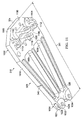
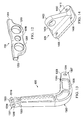
- FIG. 10 an illustration of a frame is depicted in accordance with an illustrative embodiment.
- a view of frame 318 from top side 1000 is depicted in accordance with an illustrative embodiment.
- first end 324 of frame 318 is configured to be connected to support structure 306 in Figure 3 .
- frame 318 may be comprised of connector section 1002, connector section 1004, and number of elongate members 509.
- Connector section 1004 may also be referred to as a "clevis”.
- Number of elongate members 509 may extend from connector section 1002 to connector section 1004.
- number of elongate members 509 may comprise member 1006, member 1008, and member 1010.
- number of members present in number of elongate members 509 may vary, depending on the amount of redundancy desired within number of elongate members 509 for frame 318.
- number of elongate members 509 may comprise one member, two members, five members, or some other suitable number of members.
- Connector section 1002 may be configured to be connected to second end 316 of support structure 306 in Figure 3 .
- fasteners (not shown) may connect connector section 1002 at first end 324 to second end 316 of support structure 306.
- Fasteners may be installed in holes 1011, 1012, 1014, 1016, 1018, and 1020 in connector section 1002.
- connector section 1004 may have flange 1021, flange 1022, flange 1023, and flange 1024.
- hole 1026 may be located in flange 1021
- hole 1028 may be located in flange 1022. These holes may receive fastener 608 to connect connector section 1004 to fixed link 604 in Figure 6 .
- hole 1030 may be located in flange 1023, and a hole (not shown) may be located in flange 1024. These holes may receive fastener 614 to connect connector section 1004 to floating link 606 in Figure 6 .
- FIG. 11 another view of a frame is depicted in accordance with an illustrative embodiment.
- bottom side 1100 of frame 318 may be seen in this view.
- connector section 1002 may include flange 1102, flange 1104, flange 1106, and flange 1108.
- hole 1110 in flange 1102 and hole 1112 in flange 1104 may receive bar 700 in Figure 7 .
- flange 1106 and flange 1108 may be configured to receive a fastener to hold bar 700 in place.
- a fastener may be received in hole 1114 in flange 1106 and hole 1116 in flange 1108.
- bar 700 may have end 1202 and end 1204.
- End 1202 may be configured to be received in hole 1110 of flange 1102 in Figure 11 .
- End 1204 may be configured to be received in hole 1112 of flange 1104 in Figure 11 .
- Hole 1206 may be aligned with hole 1114 in flange 1106 and hole 1116 in flange 1108 of frame 318 to receive a fastener to connect bar 700 to frame 318 in Figure 11 .
- Hole 1208 in bar 700 may be used to connect link 618 in Figure 6 to bar 700.
- Hole 1210 in bar 700 may be used to connect link 620 in Figure 6 to bar 700.
- bar 700 may allow both link 618 and link 620 to share loads.
- link 620 may have curved shape 1300.
- Link 620 has connector 1301 at end 1302.
- connector 1301 may comprise flange 1303 and flange 1304.
- Link 620 also may have connector 1307 at end 1306.
- Connector 1307 may comprise flange 1308 and flange 1310.
- flange 1308 may have hole 1314, and flange 1310 has a hole (not shown). These holes may receive fastener 624 to connect link 620 to bracket 622 in Figure 6 .
- flange 1303 may have hole 1316
- flange 1304 may have hole 1318.
- Hole 1316 and hole 1318 may receive fastener 704 to connect link 620 to bar 700 in Figure 7 .
- link 618 may have a configuration similar to link 620 as illustrated in Figure 13 .
- bracket 626 may include substantially planar section 1400 and flange 1402.
- Hole 1404 may be present in flange 1402.
- Hole 1404 may be aligned with hole 1314 in flange 1308 and a hole (not shown) in flange 1310 in Figure 13 to receive fastener 702 to connect link 618 to bracket 626.
- hole 1406, hole 1408, and hole 1410 may receive fastener 628 to connect bracket 626 to engine core case 304 in Figure 3 .
- bracket 626 may be welded or formed as part of engine core case 304.
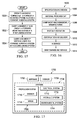
- FIG. 15 an illustration of a flowchart of a process for operating an engine is depicted in accordance with an illustrative embodiment.
- the process illustrated in Figure 15 may be implemented in aircraft 100 in Figure 1 .
- Forward mounting system 110 may comprise frame 124, first linking system 126, and second linking system 128.
- First linking system 126 may be connected to frame 124 and fan case 116.
- Second linking system 128 may be connected to frame 124 and engine core case 118.
- Number of side loads 141 may be carried by first linking system 126 in forward mounting system 110 (operation 1502).
- Number of side loads 141 may include one or more loads in a direction substantially parallel to pitch axis 146.
- Number of vertical loads 142 may be carried by second linking system 128 in forward mounting system 110 (operation 1504), with the process terminating thereafter.
- Number of vertical loads 142 may include one or more loads in a direction substantially parallel to yaw axis 148.
- each block in the flowchart or block diagrams may represent a module, segment, function, and/or a portion of an operation or step.
- the function or functions noted in the blocks may occur out of the order noted in the figures.
- two blocks shown in succession may be executed substantially concurrently, or the blocks may sometimes be performed in the reverse order, depending upon the functionality involved.
- other blocks may be added in addition to the illustrated blocks in a flowchart or block diagram.
- aircraft manufacturing and service method 1600 may be described in the context of aircraft manufacturing and service method 1600 as shown in Figure 16 and aircraft 1700 as shown in Figure 17 .
- Figure 16 an illustration of an aircraft manufacturing and service method is depicted in accordance with an illustrative embodiment.
- aircraft manufacturing and service method 1600 may include specification and design 1602 of aircraft 1700 in Figure 17 and material procurement 1604.
- aircraft 1700 may take place. Thereafter, aircraft 1700 may go through certification and delivery 1610 in order to be placed in service 1612. While in service 1612 by a customer, aircraft 1700 may be scheduled for routine maintenance and service 1614, which may include modification, reconfiguration, refurbishment, and other maintenance or service.
- Each of the processes of aircraft manufacturing and service method 1600 may be performed or carried out by a system integrator, a third party, and/or an operator.
- the operator may be a customer.
- a system integrator may include, without limitation, any number of aircraft manufacturers and major-system subcontractors
- a third party may include, without limitation, any number of vendors, subcontractors, and suppliers
- an operator may be an airline, a leasing company, a military entity, a service organization, and so on.
- aircraft 1700 may be produced by aircraft manufacturing and service method 1600 in Figure 16 and may include airframe 1702 with plurality of systems 1704 and interior 1706.
- Examples of systems 1704 may include one or more of propulsion system 1708, electrical system 1710, hydraulic system 1712, and environmental system 1714.
- Propulsion system 1708 may include engines 1716 connected to wings 1718 in airframe 1702. Any number of other systems may be included.
- an aerospace example is shown, different illustrative embodiments may be applied to other industries, such as the automotive industry.
- Apparatuses and methods embodied herein may be employed during at least one of the stages of aircraft manufacturing and service method 1600 in Figure 16 .
- components or subassemblies for engine mounting system 106 produced in component and subassembly manufacturing 1606 in Figure 16 may be fabricated or manufactured in a manner similar to components or subassemblies produced while aircraft 1700 is in service 1612 in Figure 16 .
- one or more apparatus embodiments, method embodiments, or a combination thereof for engine mounting system 106 may be manufactured during component and subassembly manufacturing 1606.
- Engine mounting system 106 may be used to mount engines 1716 in propulsion system 1708 to wings 1718 in airframe 1702.
- Forward mounting system 110 in engine mounting system 106 may be used to connect engine 102 to wing 104 during system integration 1608. Further, forward mounting system 110 may be used to carry loads in loads 144 while in service 1612. Additionally, forward mounting system 110 may be added to aircraft 1700, and a more desirable configuration for a fairing may be used during maintenance and service 1614. This change may be performed as part of routine maintenance and service 1614 or as an upgrade or reconfiguration of aircraft 1700.
- engine mounting system 106 may be configured in a manner such that fairing 109 has desired configuration 164.
- forward mounting system 110 may be configured to reduce length 122 of support structure 108 in a manner that allows for desired configuration 164 of fairing 109.
- a shape and size of fairing 109 may be provided that is more aerodynamic than if length 122 of support structure 108 is increased.
- Desired configuration 164 for fairing 109 may occur through the use of frame 124, first linking system 126, and second linking system 128. These components may distribute loads 144 carried by forward mounting system 110 between fan case 116 and engine core case 118. The distribution of loads 144 may allow frame 124 to have configuration 160 that may reduce the height or profile of frame 124 in a manner that allows for desired configuration 164 of fairing 109.
- frame 124 and first linking system 126 may carry side load 140.
- Second linking system 128 and frame 124 may carry vertical load 142.
- frame 124 may provide a common attachment location for first linking system 126 and second linking system 128. Frame 124 may allow for easier engine installation and/or removal.
Landscapes
- Engineering & Computer Science (AREA)
- Aviation & Aerospace Engineering (AREA)
- Structures Of Non-Positive Displacement Pumps (AREA)
- Connection Of Plates (AREA)
Applications Claiming Priority (1)
| Application Number | Priority Date | Filing Date | Title |
|---|---|---|---|
| US13/422,123 US9637241B2 (en) | 2012-03-16 | 2012-03-16 | Engine mounting system for an aircraft |
Publications (3)
| Publication Number | Publication Date |
|---|---|
| EP2639159A2 true EP2639159A2 (fr) | 2013-09-18 |
| EP2639159A3 EP2639159A3 (fr) | 2017-04-12 |
| EP2639159B1 EP2639159B1 (fr) | 2019-09-25 |
Family
ID=48190080
Family Applications (1)
| Application Number | Title | Priority Date | Filing Date |
|---|---|---|---|
| EP13159748.6A Active EP2639159B1 (fr) | 2012-03-16 | 2013-03-18 | Système de montage de moteur pour aéronef |
Country Status (4)
| Country | Link |
|---|---|
| US (1) | US9637241B2 (fr) |
| EP (1) | EP2639159B1 (fr) |
| JP (1) | JP6265609B2 (fr) |
| CN (1) | CN103303484B (fr) |
Cited By (4)
| Publication number | Priority date | Publication date | Assignee | Title |
|---|---|---|---|---|
| EP3048271A1 (fr) * | 2014-12-10 | 2016-07-27 | Rolls-Royce Corporation | Nervure de renfort |
| FR3040369A1 (fr) * | 2015-09-02 | 2017-03-03 | Airbus Operations Sas | Ensemble moteur d'aeronef comprenant une attache moteur avant amelioree |
| FR3071820A1 (fr) * | 2017-10-03 | 2019-04-05 | Airbus Operations | Ensemble moteur d'aeronef |
| EP3708809A3 (fr) * | 2016-03-18 | 2020-12-02 | United Technologies Corporation | Système de suspension d'échangeur de chaleur à rapport de constante de rappel tuyau/liaison |
Families Citing this family (16)
| Publication number | Priority date | Publication date | Assignee | Title |
|---|---|---|---|---|
| FR2981047B1 (fr) * | 2011-10-06 | 2013-10-25 | Aircelle Sa | Ensemble propulsif d'aeronef |
| FR2981046B1 (fr) * | 2011-10-06 | 2013-10-25 | Aircelle Sa | Ensemble propulsif d'aeronef |
| US9211955B1 (en) * | 2012-12-10 | 2015-12-15 | The Boeing Company | Methods and apparatus for supporting engines and nacelles relative to aircraft wings |
| US10144524B2 (en) * | 2013-06-14 | 2018-12-04 | Rohr, Inc. | Assembly for mounting a turbine engine to a pylon |
| US9238511B2 (en) * | 2014-03-04 | 2016-01-19 | Mra Systems, Inc. | Engine pylon structure |
| JP6437347B2 (ja) * | 2015-02-27 | 2018-12-12 | 三菱重工業株式会社 | 推力発生装置及び航空機 |
| FR3060531B1 (fr) * | 2016-12-20 | 2019-05-31 | Airbus Operations | Partie arriere d'aeronef comprenant un cadre de fuselage supportant deux moteurs partiellement enterres |
| CN108082501B (zh) * | 2017-12-13 | 2021-01-08 | 荆州市江汉众力实业有限公司 | 一种便捷式发动机支架 |
| FR3083213B1 (fr) * | 2018-06-29 | 2020-10-02 | Safran Aircraft Engines | Dispositif de resistance au feu ameliore destine a etre interpose entre une extremite de mat d'accrochage de turbomachine d'aeronef, et un capotage de la turbomachine delimitant un compartiment inter-veine |
| US20210300577A1 (en) | 2020-03-31 | 2021-09-30 | General Electric Company | Engine backbone bending reduction |
| US12246845B2 (en) | 2021-05-20 | 2025-03-11 | General Electric Company | Methods and apparatus for mounting a gas turbine engine |
| FR3124492A1 (fr) * | 2021-06-29 | 2022-12-30 | Airbus Operations (S.A.S.) | Ensemble propulseur à hélice et moteur électrique comprenant une structure primaire adaptée et aéronef comportant au moins un tel ensemble propulseur |
| GB202117778D0 (en) * | 2021-12-09 | 2022-01-26 | Rolls Royce Plc | Support structure for attaching a gas turbine engine to an aircraft pylon |
| EP4477554A1 (fr) | 2023-06-14 | 2024-12-18 | Airbus Operations (S.A.S.) | Ensemble propulsif d'aéronef comportant un turboréacteur, un mât et des moyens de fixation du turboréacteur au mât |
| EP4488180A1 (fr) * | 2023-07-06 | 2025-01-08 | Airbus Operations (S.A.S.) | Système de propulsion pour aéronef comprenant un turboréacteur, un mât et une attache moteur |
| EP4506258A1 (fr) * | 2023-08-09 | 2025-02-12 | Airbus Operations (S.A.S.) | Système de propulsion pour aéronef comprenant un turboréacteur, un mât et une attache moteur |
Family Cites Families (30)
| Publication number | Priority date | Publication date | Assignee | Title |
|---|---|---|---|---|
| GB1516980A (en) | 1974-12-24 | 1978-07-05 | Rolls Royce | Mounting ducted fan gas turbine engines on aircraft |
| GB2010969A (en) * | 1977-12-22 | 1979-07-04 | Rolls Royce | Mounting for Gas Turbine Jet Propulsion Engine |
| US4266741A (en) | 1978-05-22 | 1981-05-12 | The Boeing Company | Mounting apparatus for fan jet engine having mixed flow nozzle installation |
| US4428189A (en) | 1980-04-02 | 1984-01-31 | United Technologies Corporation | Case deflection control in aircraft gas turbine engines |
| US4437627A (en) | 1982-03-12 | 1984-03-20 | The Boeing Company | Integrated power plant installation system |
| US4471609A (en) | 1982-08-23 | 1984-09-18 | The Boeing Company | Apparatus and method for minimizing engine backbone bending |
| US4603821A (en) | 1983-12-30 | 1986-08-05 | The Boeing Company | System for mounting a jet engine |
| US4717094A (en) * | 1986-05-19 | 1988-01-05 | The Boeing Company | Aircraft engine mount system with vibration isolators |
| DE69012071T2 (de) | 1989-12-05 | 1995-04-13 | Rolls Royce Plc | Ausfallsichere Haltevorrichtung für Treibwerke. |
| US5524847A (en) | 1993-09-07 | 1996-06-11 | United Technologies Corporation | Nacelle and mounting arrangement for an aircraft engine |
| US5452575A (en) | 1993-09-07 | 1995-09-26 | General Electric Company | Aircraft gas turbine engine thrust mount |
| US6126110A (en) * | 1997-12-22 | 2000-10-03 | Mcdonnell Douglas Corporation | Horizontally opposed trunnion forward engine mount system supported beneath a wing pylon |
| FR2793768B1 (fr) * | 1999-05-17 | 2001-09-07 | Aerospatiale Airbus | Dispositif de montage sur un mat d'un ensemble propulsif d'aeronef et mat adapte a ce dispositif |
| FR2793769B1 (fr) | 1999-05-19 | 2001-09-07 | Aerospatiale Airbus | Dispositif d'accrochage d'un moteur d'aeronef a un mat |
| GB9927425D0 (en) * | 1999-11-20 | 2000-01-19 | Rolls Royce Plc | A gas turbine engine mounting arrangement |
| FR2867158B1 (fr) * | 2004-03-04 | 2007-06-08 | Airbus France | Systeme de montage interpose entre un moteur d'aeronef et une structure rigide d'un mat d'accrochage fixe sous une voilure de cet aeronef. |
| FR2873986B1 (fr) | 2004-08-04 | 2007-12-21 | Airbus France Sas | Ensemble moteur pour aeronef |
| FR2885878B1 (fr) * | 2005-05-23 | 2007-06-29 | Airbus France Sas | Ensemble moteur pour aeronef |
| FR2885877B1 (fr) | 2005-05-23 | 2008-12-12 | Airbus France Sas | Mat d'accrochage de turboreacteur pour aeronef |
| FR2891246B1 (fr) * | 2005-09-26 | 2007-10-26 | Airbus France Sas | Ensemble moteur pour aeronef comprenant un moteur ainsi qu'un dispositif d'accrochage d'un tel moteur |
| FR2891248B1 (fr) | 2005-09-28 | 2009-05-01 | Airbus France Sas | Ensemble moteur pour aeronef comprenant un moteur ainsi qu'un mat d'accrochage d'un tel moteur |
| FR2914907B1 (fr) * | 2007-04-16 | 2009-10-30 | Snecma Sa | Suspension souple avec peigne pour turbomoteur |
| FR2915175B1 (fr) * | 2007-04-20 | 2009-07-17 | Airbus France Sa | Mat d'accrochage de moteur pour aeronef disposant d'une poutre d'attache moteur arriere deportee du caisson |
| FR2924684B1 (fr) * | 2007-12-07 | 2010-01-01 | Snecma | Suspension d'un turboreacteur a un aeronef |
| FR2926788B1 (fr) * | 2008-01-25 | 2010-04-02 | Snecma | Fixation d'un turboreacteur multiflux a un aeronef |
| RU2571680C2 (ru) * | 2009-07-28 | 2015-12-20 | Снекма | Балка подвески турбинного двигателя к конструкции летательного аппарата |
| US8353476B2 (en) * | 2009-11-23 | 2013-01-15 | Spirit Aerosystems, Inc. | Truss-shaped engine pylon and method of making same |
| FR2975077B1 (fr) * | 2011-05-12 | 2013-07-05 | Airbus Operations Sas | Dispositif d'accrochage d'un moteur d'aeronef, comprenant des cales de serrage d'attache moteur a effet de coin |
| FR2981047B1 (fr) * | 2011-10-06 | 2013-10-25 | Aircelle Sa | Ensemble propulsif d'aeronef |
| GB201121971D0 (en) * | 2011-12-21 | 2012-02-01 | Rolls Royce Deutschland & Co Kg | Accessory mounting for a gas turbine |
-
2012
- 2012-03-16 US US13/422,123 patent/US9637241B2/en active Active
-
2013
- 2013-03-14 JP JP2013051216A patent/JP6265609B2/ja active Active
- 2013-03-15 CN CN201310083916.3A patent/CN103303484B/zh active Active
- 2013-03-18 EP EP13159748.6A patent/EP2639159B1/fr active Active
Non-Patent Citations (1)
| Title |
|---|
| None |
Cited By (7)
| Publication number | Priority date | Publication date | Assignee | Title |
|---|---|---|---|---|
| EP3048271A1 (fr) * | 2014-12-10 | 2016-07-27 | Rolls-Royce Corporation | Nervure de renfort |
| US10385730B2 (en) | 2014-12-10 | 2019-08-20 | Rolls-Royce Corporation | Stiffening rib |
| FR3040369A1 (fr) * | 2015-09-02 | 2017-03-03 | Airbus Operations Sas | Ensemble moteur d'aeronef comprenant une attache moteur avant amelioree |
| US10239627B2 (en) | 2015-09-02 | 2019-03-26 | Airbus Operations Sas | Aircraft engine unit comprising an improved front engine attachment |
| EP3708809A3 (fr) * | 2016-03-18 | 2020-12-02 | United Technologies Corporation | Système de suspension d'échangeur de chaleur à rapport de constante de rappel tuyau/liaison |
| FR3071820A1 (fr) * | 2017-10-03 | 2019-04-05 | Airbus Operations | Ensemble moteur d'aeronef |
| US11254437B2 (en) | 2017-10-03 | 2022-02-22 | Airbus Operations Sas | Aircraft engine assembly |
Also Published As
| Publication number | Publication date |
|---|---|
| EP2639159A3 (fr) | 2017-04-12 |
| JP2013193733A (ja) | 2013-09-30 |
| US9637241B2 (en) | 2017-05-02 |
| JP6265609B2 (ja) | 2018-01-24 |
| CN103303484A (zh) | 2013-09-18 |
| US20130240666A1 (en) | 2013-09-19 |
| EP2639159B1 (fr) | 2019-09-25 |
| CN103303484B (zh) | 2016-12-28 |
Similar Documents
| Publication | Publication Date | Title |
|---|---|---|
| EP2639159B1 (fr) | Système de montage de moteur pour aéronef | |
| EP2718185B1 (fr) | Système et procédé pour monter un moteur d'avion | |
| JP6534244B2 (ja) | ウイングレット取付具およびスプリットウイングレットを主翼に取り付ける方法 | |
| US8342444B2 (en) | Fail safe extended torque box strut-to-wing mount | |
| US8128021B2 (en) | Engine mount system for a turbofan gas turbine engine | |
| JP6944298B2 (ja) | 航空機翼に構造的支持を与えるプランク済みストリンガ | |
| US9211955B1 (en) | Methods and apparatus for supporting engines and nacelles relative to aircraft wings | |
| US10358226B2 (en) | Assembly for an aircraft including a fitting secured to the upper surface of a wing box, for mounting an engine strut to said wing box | |
| CN105000187B (zh) | 用于飞行器的组件和飞行器 | |
| US10899463B2 (en) | Segmented pylon for an aircraft propulsion system | |
| US12415610B2 (en) | Strut assembly and method for coupling an engine to a wing of an aircraft | |
| US12377993B2 (en) | Engine attachment system for aircraft and method for attaching an engine | |
| US6758439B2 (en) | Apparatuses and methods for attaching engine nacelles to aircraft | |
| US11022071B2 (en) | Load distribution panel assembly, system and method | |
| WO2009066103A1 (fr) | Fixation de mât pour moteur d'avion | |
| CN111824447A (zh) | 飞机机翼及其组装方法 | |
| US11498689B2 (en) | Attachment for suspending an aircraft engine | |
| EP2750972B1 (fr) | Système de restriction de mouvement pour un moteur d'aéronef | |
| US20070057128A1 (en) | Auxiliary power unit case flange to plate adapter |
Legal Events
| Date | Code | Title | Description |
|---|---|---|---|
| PUAI | Public reference made under article 153(3) epc to a published international application that has entered the european phase |
Free format text: ORIGINAL CODE: 0009012 |
|
| 17P | Request for examination filed |
Effective date: 20130319 |
|
| AK | Designated contracting states |
Kind code of ref document: A2 Designated state(s): AL AT BE BG CH CY CZ DE DK EE ES FI FR GB GR HR HU IE IS IT LI LT LU LV MC MK MT NL NO PL PT RO RS SE SI SK SM TR |
|
| AX | Request for extension of the european patent |
Extension state: BA ME |
|
| PUAL | Search report despatched |
Free format text: ORIGINAL CODE: 0009013 |
|
| AK | Designated contracting states |
Kind code of ref document: A3 Designated state(s): AL AT BE BG CH CY CZ DE DK EE ES FI FR GB GR HR HU IE IS IT LI LT LU LV MC MK MT NL NO PL PT RO RS SE SI SK SM TR |
|
| AX | Request for extension of the european patent |
Extension state: BA ME |
|
| RIC1 | Information provided on ipc code assigned before grant |
Ipc: B64D 27/26 20060101AFI20170306BHEP |
|
| GRAP | Despatch of communication of intention to grant a patent |
Free format text: ORIGINAL CODE: EPIDOSNIGR1 |
|
| STAA | Information on the status of an ep patent application or granted ep patent |
Free format text: STATUS: GRANT OF PATENT IS INTENDED |
|
| INTG | Intention to grant announced |
Effective date: 20190411 |
|
| GRAS | Grant fee paid |
Free format text: ORIGINAL CODE: EPIDOSNIGR3 |
|
| GRAA | (expected) grant |
Free format text: ORIGINAL CODE: 0009210 |
|
| STAA | Information on the status of an ep patent application or granted ep patent |
Free format text: STATUS: THE PATENT HAS BEEN GRANTED |
|
| AK | Designated contracting states |
Kind code of ref document: B1 Designated state(s): AL AT BE BG CH CY CZ DE DK EE ES FI FR GB GR HR HU IE IS IT LI LT LU LV MC MK MT NL NO PL PT RO RS SE SI SK SM TR |
|
| REG | Reference to a national code |
Ref country code: GB Ref legal event code: FG4D |
|
| REG | Reference to a national code |
Ref country code: CH Ref legal event code: EP |
|
| REG | Reference to a national code |
Ref country code: DE Ref legal event code: R096 Ref document number: 602013060867 Country of ref document: DE |
|
| REG | Reference to a national code |
Ref country code: AT Ref legal event code: REF Ref document number: 1183597 Country of ref document: AT Kind code of ref document: T Effective date: 20191015 |
|
| REG | Reference to a national code |
Ref country code: IE Ref legal event code: FG4D |
|
| REG | Reference to a national code |
Ref country code: NL Ref legal event code: MP Effective date: 20190925 |
|
| PG25 | Lapsed in a contracting state [announced via postgrant information from national office to epo] |
Ref country code: SE Free format text: LAPSE BECAUSE OF FAILURE TO SUBMIT A TRANSLATION OF THE DESCRIPTION OR TO PAY THE FEE WITHIN THE PRESCRIBED TIME-LIMIT Effective date: 20190925 Ref country code: HR Free format text: LAPSE BECAUSE OF FAILURE TO SUBMIT A TRANSLATION OF THE DESCRIPTION OR TO PAY THE FEE WITHIN THE PRESCRIBED TIME-LIMIT Effective date: 20190925 Ref country code: LT Free format text: LAPSE BECAUSE OF FAILURE TO SUBMIT A TRANSLATION OF THE DESCRIPTION OR TO PAY THE FEE WITHIN THE PRESCRIBED TIME-LIMIT Effective date: 20190925 Ref country code: BG Free format text: LAPSE BECAUSE OF FAILURE TO SUBMIT A TRANSLATION OF THE DESCRIPTION OR TO PAY THE FEE WITHIN THE PRESCRIBED TIME-LIMIT Effective date: 20191225 Ref country code: FI Free format text: LAPSE BECAUSE OF FAILURE TO SUBMIT A TRANSLATION OF THE DESCRIPTION OR TO PAY THE FEE WITHIN THE PRESCRIBED TIME-LIMIT Effective date: 20190925 Ref country code: NO Free format text: LAPSE BECAUSE OF FAILURE TO SUBMIT A TRANSLATION OF THE DESCRIPTION OR TO PAY THE FEE WITHIN THE PRESCRIBED TIME-LIMIT Effective date: 20191225 |
|
| REG | Reference to a national code |
Ref country code: LT Ref legal event code: MG4D |
|
| PG25 | Lapsed in a contracting state [announced via postgrant information from national office to epo] |
Ref country code: RS Free format text: LAPSE BECAUSE OF FAILURE TO SUBMIT A TRANSLATION OF THE DESCRIPTION OR TO PAY THE FEE WITHIN THE PRESCRIBED TIME-LIMIT Effective date: 20190925 Ref country code: LV Free format text: LAPSE BECAUSE OF FAILURE TO SUBMIT A TRANSLATION OF THE DESCRIPTION OR TO PAY THE FEE WITHIN THE PRESCRIBED TIME-LIMIT Effective date: 20190925 Ref country code: GR Free format text: LAPSE BECAUSE OF FAILURE TO SUBMIT A TRANSLATION OF THE DESCRIPTION OR TO PAY THE FEE WITHIN THE PRESCRIBED TIME-LIMIT Effective date: 20191226 |
|
| REG | Reference to a national code |
Ref country code: AT Ref legal event code: MK05 Ref document number: 1183597 Country of ref document: AT Kind code of ref document: T Effective date: 20190925 |
|
| PG25 | Lapsed in a contracting state [announced via postgrant information from national office to epo] |
Ref country code: PT Free format text: LAPSE BECAUSE OF FAILURE TO SUBMIT A TRANSLATION OF THE DESCRIPTION OR TO PAY THE FEE WITHIN THE PRESCRIBED TIME-LIMIT Effective date: 20200127 Ref country code: IT Free format text: LAPSE BECAUSE OF FAILURE TO SUBMIT A TRANSLATION OF THE DESCRIPTION OR TO PAY THE FEE WITHIN THE PRESCRIBED TIME-LIMIT Effective date: 20190925 Ref country code: ES Free format text: LAPSE BECAUSE OF FAILURE TO SUBMIT A TRANSLATION OF THE DESCRIPTION OR TO PAY THE FEE WITHIN THE PRESCRIBED TIME-LIMIT Effective date: 20190925 Ref country code: RO Free format text: LAPSE BECAUSE OF FAILURE TO SUBMIT A TRANSLATION OF THE DESCRIPTION OR TO PAY THE FEE WITHIN THE PRESCRIBED TIME-LIMIT Effective date: 20190925 Ref country code: AT Free format text: LAPSE BECAUSE OF FAILURE TO SUBMIT A TRANSLATION OF THE DESCRIPTION OR TO PAY THE FEE WITHIN THE PRESCRIBED TIME-LIMIT Effective date: 20190925 Ref country code: NL Free format text: LAPSE BECAUSE OF FAILURE TO SUBMIT A TRANSLATION OF THE DESCRIPTION OR TO PAY THE FEE WITHIN THE PRESCRIBED TIME-LIMIT Effective date: 20190925 Ref country code: PL Free format text: LAPSE BECAUSE OF FAILURE TO SUBMIT A TRANSLATION OF THE DESCRIPTION OR TO PAY THE FEE WITHIN THE PRESCRIBED TIME-LIMIT Effective date: 20190925 Ref country code: EE Free format text: LAPSE BECAUSE OF FAILURE TO SUBMIT A TRANSLATION OF THE DESCRIPTION OR TO PAY THE FEE WITHIN THE PRESCRIBED TIME-LIMIT Effective date: 20190925 Ref country code: AL Free format text: LAPSE BECAUSE OF FAILURE TO SUBMIT A TRANSLATION OF THE DESCRIPTION OR TO PAY THE FEE WITHIN THE PRESCRIBED TIME-LIMIT Effective date: 20190925 |
|
| PG25 | Lapsed in a contracting state [announced via postgrant information from national office to epo] |
Ref country code: IS Free format text: LAPSE BECAUSE OF FAILURE TO SUBMIT A TRANSLATION OF THE DESCRIPTION OR TO PAY THE FEE WITHIN THE PRESCRIBED TIME-LIMIT Effective date: 20200224 Ref country code: SK Free format text: LAPSE BECAUSE OF FAILURE TO SUBMIT A TRANSLATION OF THE DESCRIPTION OR TO PAY THE FEE WITHIN THE PRESCRIBED TIME-LIMIT Effective date: 20190925 Ref country code: SM Free format text: LAPSE BECAUSE OF FAILURE TO SUBMIT A TRANSLATION OF THE DESCRIPTION OR TO PAY THE FEE WITHIN THE PRESCRIBED TIME-LIMIT Effective date: 20190925 Ref country code: CZ Free format text: LAPSE BECAUSE OF FAILURE TO SUBMIT A TRANSLATION OF THE DESCRIPTION OR TO PAY THE FEE WITHIN THE PRESCRIBED TIME-LIMIT Effective date: 20190925 |
|
| REG | Reference to a national code |
Ref country code: DE Ref legal event code: R097 Ref document number: 602013060867 Country of ref document: DE |
|
| PG2D | Information on lapse in contracting state deleted |
Ref country code: IS |
|
| PG25 | Lapsed in a contracting state [announced via postgrant information from national office to epo] |
Ref country code: DK Free format text: LAPSE BECAUSE OF FAILURE TO SUBMIT A TRANSLATION OF THE DESCRIPTION OR TO PAY THE FEE WITHIN THE PRESCRIBED TIME-LIMIT Effective date: 20190925 Ref country code: IS Free format text: LAPSE BECAUSE OF FAILURE TO SUBMIT A TRANSLATION OF THE DESCRIPTION OR TO PAY THE FEE WITHIN THE PRESCRIBED TIME-LIMIT Effective date: 20200126 |
|
| PLBE | No opposition filed within time limit |
Free format text: ORIGINAL CODE: 0009261 |
|
| STAA | Information on the status of an ep patent application or granted ep patent |
Free format text: STATUS: NO OPPOSITION FILED WITHIN TIME LIMIT |
|
| 26N | No opposition filed |
Effective date: 20200626 |
|
| PG25 | Lapsed in a contracting state [announced via postgrant information from national office to epo] |
Ref country code: MC Free format text: LAPSE BECAUSE OF FAILURE TO SUBMIT A TRANSLATION OF THE DESCRIPTION OR TO PAY THE FEE WITHIN THE PRESCRIBED TIME-LIMIT Effective date: 20190925 |
|
| REG | Reference to a national code |
Ref country code: CH Ref legal event code: PL |
|
| PG25 | Lapsed in a contracting state [announced via postgrant information from national office to epo] |
Ref country code: SI Free format text: LAPSE BECAUSE OF FAILURE TO SUBMIT A TRANSLATION OF THE DESCRIPTION OR TO PAY THE FEE WITHIN THE PRESCRIBED TIME-LIMIT Effective date: 20190925 |
|
| REG | Reference to a national code |
Ref country code: BE Ref legal event code: MM Effective date: 20200331 |
|
| PG25 | Lapsed in a contracting state [announced via postgrant information from national office to epo] |
Ref country code: LU Free format text: LAPSE BECAUSE OF NON-PAYMENT OF DUE FEES Effective date: 20200318 |
|
| PG25 | Lapsed in a contracting state [announced via postgrant information from national office to epo] |
Ref country code: CH Free format text: LAPSE BECAUSE OF NON-PAYMENT OF DUE FEES Effective date: 20200331 Ref country code: IE Free format text: LAPSE BECAUSE OF NON-PAYMENT OF DUE FEES Effective date: 20200318 Ref country code: LI Free format text: LAPSE BECAUSE OF NON-PAYMENT OF DUE FEES Effective date: 20200331 |
|
| PG25 | Lapsed in a contracting state [announced via postgrant information from national office to epo] |
Ref country code: BE Free format text: LAPSE BECAUSE OF NON-PAYMENT OF DUE FEES Effective date: 20200331 |
|
| PG25 | Lapsed in a contracting state [announced via postgrant information from national office to epo] |
Ref country code: TR Free format text: LAPSE BECAUSE OF FAILURE TO SUBMIT A TRANSLATION OF THE DESCRIPTION OR TO PAY THE FEE WITHIN THE PRESCRIBED TIME-LIMIT Effective date: 20190925 Ref country code: MT Free format text: LAPSE BECAUSE OF FAILURE TO SUBMIT A TRANSLATION OF THE DESCRIPTION OR TO PAY THE FEE WITHIN THE PRESCRIBED TIME-LIMIT Effective date: 20190925 Ref country code: CY Free format text: LAPSE BECAUSE OF FAILURE TO SUBMIT A TRANSLATION OF THE DESCRIPTION OR TO PAY THE FEE WITHIN THE PRESCRIBED TIME-LIMIT Effective date: 20190925 |
|
| PG25 | Lapsed in a contracting state [announced via postgrant information from national office to epo] |
Ref country code: MK Free format text: LAPSE BECAUSE OF FAILURE TO SUBMIT A TRANSLATION OF THE DESCRIPTION OR TO PAY THE FEE WITHIN THE PRESCRIBED TIME-LIMIT Effective date: 20190925 |
|
| P01 | Opt-out of the competence of the unified patent court (upc) registered |
Effective date: 20230516 |
|
| REG | Reference to a national code |
Ref country code: DE Ref legal event code: R079 Ref document number: 602013060867 Country of ref document: DE Free format text: PREVIOUS MAIN CLASS: B64D0027260000 Ipc: B64D0027400000 |
|
| PGFP | Annual fee paid to national office [announced via postgrant information from national office to epo] |
Ref country code: GB Payment date: 20260327 Year of fee payment: 14 |
|
| PGFP | Annual fee paid to national office [announced via postgrant information from national office to epo] |
Ref country code: DE Payment date: 20260327 Year of fee payment: 14 |
|
| PGFP | Annual fee paid to national office [announced via postgrant information from national office to epo] |
Ref country code: FR Payment date: 20260325 Year of fee payment: 14 |