EP2639401A1 - Surveillance en temps réel de puits de forage et analyse de contribution de fracture - Google Patents
Surveillance en temps réel de puits de forage et analyse de contribution de fracture Download PDFInfo
- Publication number
- EP2639401A1 EP2639401A1 EP13159586.0A EP13159586A EP2639401A1 EP 2639401 A1 EP2639401 A1 EP 2639401A1 EP 13159586 A EP13159586 A EP 13159586A EP 2639401 A1 EP2639401 A1 EP 2639401A1
- Authority
- EP
- European Patent Office
- Prior art keywords
- fractures
- fractured intervals
- time
- production
- determining
- Prior art date
- Legal status (The legal status is an assumption and is not a legal conclusion. Google has not performed a legal analysis and makes no representation as to the accuracy of the status listed.)
- Granted
Links
- 238000012544 monitoring process Methods 0.000 title description 4
- 238000004458 analytical method Methods 0.000 title description 3
- 238000004519 manufacturing process Methods 0.000 claims description 74
- 238000000034 method Methods 0.000 claims description 26
- 229930195733 hydrocarbon Natural products 0.000 claims description 21
- 150000002430 hydrocarbons Chemical class 0.000 claims description 21
- 238000009826 distribution Methods 0.000 claims description 17
- 238000009530 blood pressure measurement Methods 0.000 claims description 12
- 230000001052 transient effect Effects 0.000 claims description 11
- 238000012545 processing Methods 0.000 claims description 6
- 206010017076 Fracture Diseases 0.000 description 108
- 208000010392 Bone Fractures Diseases 0.000 description 38
- 238000005259 measurement Methods 0.000 description 21
- 239000004215 Carbon black (E152) Substances 0.000 description 13
- 238000005070 sampling Methods 0.000 description 13
- 239000012530 fluid Substances 0.000 description 9
- 230000035699 permeability Effects 0.000 description 5
- 230000008859 change Effects 0.000 description 4
- 238000012360 testing method Methods 0.000 description 4
- 238000010586 diagram Methods 0.000 description 3
- 238000005553 drilling Methods 0.000 description 3
- 230000003287 optical effect Effects 0.000 description 3
- 208000006670 Multiple fractures Diseases 0.000 description 2
- 238000013459 approach Methods 0.000 description 2
- 238000009529 body temperature measurement Methods 0.000 description 2
- 238000004364 calculation method Methods 0.000 description 2
- 238000004891 communication Methods 0.000 description 2
- 239000000203 mixture Substances 0.000 description 2
- 230000000638 stimulation Effects 0.000 description 2
- XLYOFNOQVPJJNP-UHFFFAOYSA-N water Substances O XLYOFNOQVPJJNP-UHFFFAOYSA-N 0.000 description 2
- 230000008901 benefit Effects 0.000 description 1
- 238000013500 data storage Methods 0.000 description 1
- 238000011161 development Methods 0.000 description 1
- 230000000694 effects Effects 0.000 description 1
- 238000005516 engineering process Methods 0.000 description 1
- 238000011156 evaluation Methods 0.000 description 1
- 239000000835 fiber Substances 0.000 description 1
- 230000006870 function Effects 0.000 description 1
- 238000009434 installation Methods 0.000 description 1
- 238000013178 mathematical model Methods 0.000 description 1
- 238000005457 optimization Methods 0.000 description 1
- 230000008569 process Effects 0.000 description 1
- 238000012552 review Methods 0.000 description 1
- 239000000126 substance Substances 0.000 description 1
- 238000010200 validation analysis Methods 0.000 description 1
- 230000003442 weekly effect Effects 0.000 description 1
Images


Classifications
-
- E—FIXED CONSTRUCTIONS
- E21—EARTH OR ROCK DRILLING; MINING
- E21B—EARTH OR ROCK DRILLING; OBTAINING OIL, GAS, WATER, SOLUBLE OR MELTABLE MATERIALS OR A SLURRY OF MINERALS FROM WELLS
- E21B49/00—Testing the nature of borehole walls; Formation testing; Methods or apparatus for obtaining samples of soil or well fluids, specially adapted to earth drilling or wells
-
- E—FIXED CONSTRUCTIONS
- E21—EARTH OR ROCK DRILLING; MINING
- E21B—EARTH OR ROCK DRILLING; OBTAINING OIL, GAS, WATER, SOLUBLE OR MELTABLE MATERIALS OR A SLURRY OF MINERALS FROM WELLS
- E21B47/00—Survey of boreholes or wells
- E21B47/10—Locating fluid leaks, intrusions or movements
- E21B47/103—Locating fluid leaks, intrusions or movements using thermal measurements
-
- E—FIXED CONSTRUCTIONS
- E21—EARTH OR ROCK DRILLING; MINING
- E21B—EARTH OR ROCK DRILLING; OBTAINING OIL, GAS, WATER, SOLUBLE OR MELTABLE MATERIALS OR A SLURRY OF MINERALS FROM WELLS
- E21B43/00—Methods or apparatus for obtaining oil, gas, water, soluble or meltable materials or a slurry of minerals from wells
- E21B43/25—Methods for stimulating production
- E21B43/26—Methods for stimulating production by forming crevices or fractures
Definitions
- Embodiments of the present invention generally relate to hydrocarbon production and, more particularly, to determining the individual contribution of fractured intervals (or fractures) in time.
- Embodiments of the invention generally relate to allocating production of each of a plurality of fractured intervals (or fractures). This allocation may be performed by combining temperature distribution (and pressure) measurements, a real-time surface multiphase flow measurement, and an inflow model for each fractured interval (or fracture).
- One embodiment of the invention is a method for determining production of hydrocarbons.
- the method generally includes determining a temperature distribution associated with a plurality of fractured intervals or fractures disposed along a well; measuring a total flow rate for the well; modeling an inflow rate for each of the plurality of fractured intervals or fractures; and allocating production of each of the plurality of fractured intervals or fractures based on the temperature distribution, the total flow rate, and the inflow rates.
- the system generally includes a temperature sensing device configured to determine a temperature distribution associated with a plurality of fractured intervals or fractures disposed along a well, a flowmeter configured to measure a total flow rate for the well, and a processing unit.
- the processing unit is typically configured to model an inflow rate for each of the plurality of fractured intervals or fractures and to allocate production of each of the plurality of fractured intervals or fractures based on the temperature distribution, the total flow rate, and the inflow rates.
- Yet another embodiment of the invention provides a system for determining production hydrocarbons.
- the system generally includes means for determining a temperature distribution associated with a plurality of fractured intervals or fractures disposed along a well; means for measuring a total flow rate for the well; means for modeling an inflow rate for each of the plurality of fractured intervals or fractures; and means for allocating production of each of the plurality of fractured intervals or fractures based on the temperature distribution, the total flow rate, and the inflow rates.
- FIG. 1 is a conceptual diagram of a system for producing hydrocarbons, the system having a pipe inside a casing and downhole tools positioned at various locations along the pipe, in accordance with an embodiment of the invention.
- FIG. 2 illustrates an ideal reservoir model with multiple fractures, in accordance with an embodiment of the invention.
- FIG. 3 illustrates hydrocarbon production allocation from multiple wells, in accordance with an embodiment of the invention.
- FIG. 4 illustrates hydrocarbon production allocation from a horizontal well with multiple fractured intervals, in accordance with an embodiment of the invention.
- FIG. 5 is a flow diagram of example operations for allocating hydrocarbon production to multiple fractured intervals (or fractures), in accordance with an embodiment of the invention.
- FIG. 6 illustrates a workflow for identifying and calculating the contribution of each fractured interval (or fracture), in accordance with an embodiment of the invention.
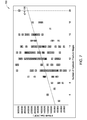
- FIG. 7 illustrates an example plot of gas production versus number of contributing fractures, in accordance with an embodiment of the invention.
- Embodiments of the invention provide techniques and apparatus for calculating production of each of a plurality of fractured intervals (or fractures) and monitoring changes in the fracture contribution with time. Such real-time monitoring and analysis may be based on a combination of different measurements in the wellbore, on the surface, and from a mathematical model, as described below. In this manner, the industry may be able to understand the behavior of fractures and, in turn, optimize the number of stages ( i.e ., fractured intervals), the number of fractures, and the spacing between fractures and stages.
- a hydrocarbon production system 100 containing one or more production pipes 102 (also known as production tubing) that may extend downward through a casing 104 to one or more hydrocarbon sources 106 ( e.g. , reservoirs).
- An annulus 108 may exist between the pipe 102 and the casing 104.
- Each production pipe 102 may include one or more lateral sections ( e.g. , created by horizontal drilling) that branch off to access different hydrocarbon sources 106 or different areas of the same hydrocarbon source 106.
- the fluid mixture may flow from sources 106 to the well completion through the production pipes 102, as indicated by fluid flow 130.
- the production pipe 102 may include one or more tools 122 for performing various tasks (e.g.
- the tools 122 may be any type of downhole device, such as a flow control device (e.g. , a valve), a sensor (e.g. , a pressure, temperature or fluid flow sensor) or other instrument, an actuator ( e.g. , a solenoid), a data storage device ( e.g. , a programmable memory), a communication device ( e.g. , a transmitter or a receiver), etc.
- a flow control device e.g. , a valve
- a sensor e.g. , a pressure, temperature or fluid flow sensor
- an actuator e.g. , a solenoid
- a data storage device e.g. , a programmable memory
- a communication device e.g. , a transmitter or a receiver
- Each tool 122 may be incorporated into an existing section of production pipe 102 or may be incorporated into a specific pipe section that is inserted in line with the production pipe 102.
- the distributed scheme of tools 122 shown in FIG. 1 may permit an operator of the system 100 to determine, for example, the level of depletion of the hydrocarbon reservoir. This information may permit the operator to monitor and intelligently control production of the hydrocarbon reservoir.
- microseismic and production logs have helped in the fracture evaluation to determine the drainage volume and fracture inflow.
- Microseismic can provide useful information on the development of fracture symmetry, half-length, azimuth, width and height, and their dependence on the treatment parameters and reservoir characteristics. Additionally, these fracture geometries in conjunction with other measured or calculated parameters (e.g. , rates, inflow models, etc.) can be used to better understand fracture modeling and production characteristics.
- Embodiments of the invention provide methods and apparatus to optimize, or at least increase, the production of horizontal fractured wells in shale reservoirs, for example.
- methods described herein enable the optimization of the number of fractures, the spacing of fractures, and the length of the horizontal section by determining the contribution of the fracture stages (or the fractures) over time.
- each fracture stage may be calculated in an analogous way to that performed in a traditional field, where the total production rates are allocated to each production well using well testing measurements, done periodically with daily measurement information like wellhead pressure.
- an acceptable production allocation can be made as a function of time. Because the system is transient, such allocation may be performed on a real-time basis.
- the idealized system 200 shown in FIG. 2 may be used to model the reservoir.
- multiple fractures 204, 206 are represented as spaced along and transverse to the horizontal well trajectory 202. Assuming fracturing conditions were the same, the length and width of each fracture in the fracture stage may be considered equal.
- These parallel fractures are formed in an area ( e.g. , a shale reservoir) with essentially zero permeability (as illustrated in the region 212 unshaded in FIG. 2 ), thereby forming a region 214 of modified permeability (shaded in FIG. 2 ), essentially creating a reservoir where none existed before.
- N frac any number of fractures
- five fractures are illustrated in the fracture stage of FIG. 2 (two external fractures 204 and three internal fractures 206) with equal fracture spacing.
- the fracture stage is defined by confining external boundaries 210.
- FIG. 2 shows that external fractures 204 are confined by virtual no-flow boundaries 208, which force the external fractures to have the same behavior as the internal fractures 206, and pure linear flow initially occurs. In shale gas reservoirs of nanodarcy permeability, pure linear flow opposite the fracture faces occurs for very long times.
- SRV Stimulated Reservoir Volume
- DTS distributed temperature sensing
- ATS multi-point or array temperature sensing
- FIG. 3 illustrates a multi-well system 300 in an oil/gas production field, in which hydrocarbon production may be allocated to each of the wells.
- periodical (e.g. , 15 days to weeks or months) production well tests are performed on each individual well, and daily (or in some cases, every few hours) pressure (P) and/or temperature (T) measurements at or near the wellhead 302 of each well are registered.
- the produced fluids from each well may be collected at a manifold and then separated by a separator 310 into oil, gas, and water.
- Daily (or in some cases, every few hours or minutes) total flow rates of oil (Qo), gas (Qg), and water (Qw) may be measured.
- the well performance (P vs. Q relation) for each well at the wellhead 302 is calculated. The use of this wellhead performance with frequent wellhead pressure measurements allows the flow rates of each individual well to be determined.
- an allocation factor (K) is found using the relationship between the total flow rate (Qt) measured and the sum of the individual well flow rates ( ⁇ Qi) and may be subsequently used.
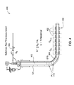
- FIG. 4 illustrates a system 400 for allocating hydrocarbon produced from a horizontal well with multiple fractured intervals 402 along a horizontal well, in accordance with an embodiment of the invention. Although seven fractured intervals 402, each with five fractures 404, are shown in FIG. 4 , any number of fractured intervals and any number of fractures per interval may be used.
- the system 400 also includes a multiphase real-time flowmeter 406 and a DTS cable 408 disposed downhole.
- the system may also include one or more sensors 410 for measuring pressure (P) and/or temperature (T), which may be disposed anywhere in the wellbore, such as in the vertical section as shown.
- P pressure
- T temperature
- the multiphase flowmeter 406 may be installed at or adjacent the wellhead or within the wellbore and, for some embodiments, may be an optical flowmeter (e.g. , an optical downhole flowmeter).
- the DTS cable 408 may be installed adjacent the casing 104, as shown in FIG. 4 .
- each stage (i.e. , fractured interval 402) in FIG. 4 is akin to a producing well.
- the variation of temperature and a transient inflow model it is possible to calculate the production of each stage at any time. In fact, if the temperature variation is high enough to distinguish between fractures 404, it may also be possible to allocate the production of each particular fracture.
- each stage or fracture may be considered as an individual contributor to production
- the main characteristics of the fractures e.g. , length and width
- the inflow rate of each fracture will be computed by an analytical transient model and combined with the change in temperature (as determined by the DTS cable 408, for example) at each stage referenced to an initial condition prior to fracturing.
- Qt total flow rate measured by the multiphase flowmeter 406
- FIG. 5 is a flow diagram of example operations 500 for determining the contribution to hydrocarbon production of each fractured interval (or each fracture).
- the operations 500 may begin, at 502, by determining a temperature distribution associated with a plurality of fractured intervals or fractures disposed along a well.
- the temperature distribution may be determined by performing at least one of distributed temperature sensing (DTS) or array temperature sensing (ATS).
- DTS distributed temperature sensing
- ATS array temperature sensing
- the plurality of fractured intervals or fractures may be located in a shale reservoir, for example.
- a total flow rate of a fluid (or any combination of fluids) produced by the well is measured.
- the total flow rate may be a total gas flow rate or a total oil flow rate, for example.
- the total flow rate may be measured using a flowmeter disposed at the surface.
- the flowmeter may be disposed at or adjacent a wellhead of the well.
- An inflow rate is modeled at 506 for each of the plurality of fractured intervals or fractures.
- the inflow rate may be an inflow gas rate or an inflow oil rate, for example.
- allocating the production at 508 may include: (1) determining a first temperature value T 0 at a first time t 0 ( e.g. , before production starts) for each of the plurality of fractured intervals or fractures; (2) determining a second temperature value T n at a second time t n ( e.g.
- the operations 500 may also include repeating the determining at 502, the measuring at 504, and the modeling at 506 within a period short enough to observe transient behavior of the plurality of fractured intervals or fractures.
- the determining, measuring, and/or modeling described above may be performed and repeated with any desired frequency (at any desired rate or periodicity).
- the determining, measuring, and/or modeling may be performed continuously, hourly, daily, weekly, or with other frequencies.
- the operations 500 may also include determining one or more pressure measurements for the well.
- allocation of the production at 508 may also be based on the pressure measurements.
- the pressure measurements may be made by one or more pressure sensors located downhole, along the horizontal or vertical portion of the wellbore.
- the pressure sensors may be optical-based pressure sensors having one or more fiber Bragg gratings (FBGs) located therein.
- FBGs fiber Bragg gratings
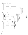
- FIG. 6 illustrates a workflow 600 for identifying and calculating the contribution of each fractured interval (or fracture), in accordance with an embodiment of the invention.
- the workflow 600 can be easily expanded to production allocation for each fracture, as long as the temperature variation is high enough to distinguish between fractures.
- the DTS (or ATS) data 602 is related to the geothermal gradient value for each stage 402.
- the cable 408 may be sampled with some periodicity to generate the data 602, leading to temperature measurements at certain sampling times (t n ).
- the delta temperature ( ⁇ T) between the temperature at the sampling time and at time t 0 is calculated for each stage 402.
- the ⁇ T values for each stage are divided by Tg to normalize the data.
- pressure measurements e.g. , taken by the sensors 410) may be used to ensure accuracy of the ⁇ T values for each stage ( e.g. , by correlation with the temperature measurements).
- a ratio (( ⁇ T/Tg)/( ⁇ T/Tg)max) for the sampling time (t n ) is calculated for each stage 402.
- the ratio for each stage is calculated by dividing the Tg-normalized ⁇ T value for this particular stage by the maximum Tg-normalized ⁇ T value over all previous times for this stage.
- the ⁇ T value at time t 0 is initially assumed to be the maximum Tg-normalized ⁇ T value, so the ratio in this case will be 1.
- the maximum ⁇ T value is stored for later validation of this assumption.
- inflow transient models are run to generate inflow rates for each stage 402 (indexed by "i").
- the workflow 600 of FIG. 6 generates inflow gas rates for each stage (Qgfi), but inflow oil rates or both may also be used.
- the inflow transient models either produce the inflow rates at the sampling time (t n ) as shown at 610, or interpolation or other techniques are used to determine inflow rates at the sampling time based on inflow rates produced for other times.
- the ratio at the sampling time (t n ) for each stage calculated at 606 is multiplied with the modeled inflow rate for each stage from 610 corresponding to the sampling time.
- surface multiphase measurements may be made at 614, for example, by the flowmeter 406, to generate one or more total flow rates (Qg, Qo, and/or Qw) for the well.
- the total flow rates may either be generated at the sampling time (t n ) as shown at 616, or interpolation or other techniques may be used to determine the total flow rates at sampling time based on measurements taken at other times.
- results of the multiplications at 612 for each of the stages 402 at the sampling time (t n ) may be summed ( ⁇ Q'gfi). At 618, this sum may be compared to the total gas flow rate (Qg) corresponding to the sampling time (t n ).
- the ratio for each stage 402 calculated at 606 is multiplied by the Qgfi at t 0 for each stage at 612, and the sum of all Qgfi values is compared to the Qg corresponding to to at 618.
- the value of ⁇ T 1 will be compared to the value of ⁇ T 0 . If ⁇ T 1 is bigger, then a new maximum value is obtained.
- This new maximum value replaces the previous value, and in this case the contribution of this particular stage will be 100% during this period of time, and the assumption on the previous time step was wrong.
- a new calculation for t 0 will be performed to correct the first assumption and similarly at any time that a new maximum value is found.
- the workflow 600 operating on a "real-time" basis, will increase well productivity, helping to determine what is the optimal choke size to flow back the well and to have all fractures contributing (or to find out which fractures do not contribute at all).
- a normalized graph of production versus a number of contributing stages and/or fractures can be obtained and, based on these results, an optimal number of stages and/or fractures may be determined.
- a good relationship is expected of production versus number of contributing fractures, more consistent than the plot 700 of gas production versus number of contributing fractures shown in FIG. 7 (from Modeland N.
- DTS distributed temperature sensing
- ATS multi-point or array temperature sensing
Landscapes
- Geology (AREA)
- Life Sciences & Earth Sciences (AREA)
- Engineering & Computer Science (AREA)
- Mining & Mineral Resources (AREA)
- Physics & Mathematics (AREA)
- Environmental & Geological Engineering (AREA)
- Fluid Mechanics (AREA)
- General Life Sciences & Earth Sciences (AREA)
- Geochemistry & Mineralogy (AREA)
- Geophysics (AREA)
- Measuring Fluid Pressure (AREA)
- Production Of Liquid Hydrocarbon Mixture For Refining Petroleum (AREA)
- Testing Of Devices, Machine Parts, Or Other Structures Thereof (AREA)
- Testing Or Calibration Of Command Recording Devices (AREA)
Applications Claiming Priority (1)
| Application Number | Priority Date | Filing Date | Title |
|---|---|---|---|
| US201261611924P | 2012-03-16 | 2012-03-16 |
Publications (2)
| Publication Number | Publication Date |
|---|---|
| EP2639401A1 true EP2639401A1 (fr) | 2013-09-18 |
| EP2639401B1 EP2639401B1 (fr) | 2016-05-04 |
Family
ID=48049763
Family Applications (1)
| Application Number | Title | Priority Date | Filing Date |
|---|---|---|---|
| EP13159586.0A Not-in-force EP2639401B1 (fr) | 2012-03-16 | 2013-03-15 | Surveillance en temps réel de puits de forage et analyse de contribution de fracture |
Country Status (7)
| Country | Link |
|---|---|
| US (1) | US20130245953A1 (fr) |
| EP (1) | EP2639401B1 (fr) |
| CN (1) | CN103306664A (fr) |
| AR (1) | AR090353A1 (fr) |
| AU (1) | AU2013201757B2 (fr) |
| BR (1) | BR102013006266B1 (fr) |
| CA (1) | CA2808858C (fr) |
Families Citing this family (16)
| Publication number | Priority date | Publication date | Assignee | Title |
|---|---|---|---|---|
| US10400580B2 (en) | 2015-07-07 | 2019-09-03 | Schlumberger Technology Corporation | Temperature sensor technique for determining a well fluid characteristic |
| US10415382B2 (en) * | 2016-05-03 | 2019-09-17 | Schlumberger Technology Corporation | Method and system for establishing well performance during plug mill-out or cleanout/workover operations |
| US11263370B2 (en) | 2016-08-25 | 2022-03-01 | Enverus, Inc. | Systems and methods for allocating hydrocarbon production values |
| US10303819B2 (en) | 2016-08-25 | 2019-05-28 | Drilling Info, Inc. | Systems and methods for allocating hydrocarbon production values |
| US11892579B2 (en) * | 2016-09-30 | 2024-02-06 | Schlumberger Technology Corporation | Crosswell microseismic system |
| US10584577B2 (en) | 2018-03-13 | 2020-03-10 | Saudi Arabian Oil Company | In-situ reservoir depletion management based on surface characteristics of production |
| CN110318742B (zh) * | 2018-03-30 | 2022-07-15 | 中国石油化工股份有限公司 | 基于压裂井生产数据确定裂缝闭合长度的方法和系统 |
| US11808121B2 (en) | 2018-08-16 | 2023-11-07 | Fervo Energy Company | Methods and systems to control flow and heat transfer between subsurface wellbores connected hydraulically by fractures |
| US11293280B2 (en) * | 2018-12-19 | 2022-04-05 | Exxonmobil Upstream Research Company | Method and system for monitoring post-stimulation operations through acoustic wireless sensor network |
| US11326440B2 (en) | 2019-09-18 | 2022-05-10 | Exxonmobil Upstream Research Company | Instrumented couplings |
| CN111255442B (zh) * | 2020-01-14 | 2023-04-07 | 大庆油田有限责任公司 | 一种利用干扰试井理论评价压裂裂缝方法 |
| CN112878982B (zh) * | 2020-12-31 | 2022-03-01 | 西南石油大学 | 一种考虑裂缝长期导流能力的深层页岩气产能预测方法 |
| CN113187472B (zh) * | 2021-05-11 | 2023-09-26 | 中国石油天然气股份有限公司 | 一种层状砂岩油藏水驱开发渗流优势通道的识别方法 |
| US20250075617A1 (en) * | 2022-03-07 | 2025-03-06 | Talgat Shokanov | Method of using non-magnetic solid tracers |
| CN115977615A (zh) * | 2023-01-03 | 2023-04-18 | 上海达坦能源科技股份有限公司 | 压裂效果评价方法、系统、介质及电子设备 |
| CN117888841B (zh) * | 2024-03-15 | 2024-05-17 | 江苏卫东机械有限公司 | 智能反馈控制电动钻井阀 |
Citations (4)
| Publication number | Priority date | Publication date | Assignee | Title |
|---|---|---|---|---|
| US3913398A (en) * | 1973-10-09 | 1975-10-21 | Schlumberger Technology Corp | Apparatus and method for determining fluid flow rates from temperature log data |
| US4520666A (en) * | 1982-12-30 | 1985-06-04 | Schlumberger Technology Corp. | Methods and apparatus for determining flow characteristics of a fluid in a well from temperature measurements |
| US20100032156A1 (en) * | 2008-08-08 | 2010-02-11 | Alta Rock Energy, Inc. | Method for testing an engineered geothermal system using one stimulated well |
| US20100299124A1 (en) * | 2009-05-22 | 2010-11-25 | Baker Hughes Incorporated | Apparatus and Method for Modeling Well Designs and Well Performance |
Family Cites Families (7)
| Publication number | Priority date | Publication date | Assignee | Title |
|---|---|---|---|---|
| US6142229A (en) * | 1998-09-16 | 2000-11-07 | Atlantic Richfield Company | Method and system for producing fluids from low permeability formations |
| AU2001293809A1 (en) * | 2000-09-12 | 2002-03-26 | Sofitech N.V. | Evaluation of multilayer reservoirs |
| US6789937B2 (en) * | 2001-11-30 | 2004-09-14 | Schlumberger Technology Corporation | Method of predicting formation temperature |
| US7703525B2 (en) * | 2004-12-03 | 2010-04-27 | Halliburton Energy Services, Inc. | Well perforating and fracturing |
| WO2009139949A1 (fr) * | 2008-05-13 | 2009-11-19 | Exxonmobil Upstream Research Company | Modélisation de gisements d'hydrocarbures utilisant des modèles de plans d'expériences |
| CN201334901Y (zh) * | 2008-07-01 | 2009-10-28 | 电子科大科园股份有限公司 | 气体钻井安全实时监测系统 |
| US8788251B2 (en) * | 2010-05-21 | 2014-07-22 | Schlumberger Technology Corporation | Method for interpretation of distributed temperature sensors during wellbore treatment |
-
2013
- 2013-03-11 CA CA2808858A patent/CA2808858C/fr active Active
- 2013-03-14 US US13/828,055 patent/US20130245953A1/en not_active Abandoned
- 2013-03-15 AU AU2013201757A patent/AU2013201757B2/en active Active
- 2013-03-15 BR BR102013006266-9A patent/BR102013006266B1/pt active IP Right Grant
- 2013-03-15 EP EP13159586.0A patent/EP2639401B1/fr not_active Not-in-force
- 2013-03-15 AR ARP130100848A patent/AR090353A1/es active IP Right Grant
- 2013-03-18 CN CN2013100850393A patent/CN103306664A/zh active Pending
Patent Citations (4)
| Publication number | Priority date | Publication date | Assignee | Title |
|---|---|---|---|---|
| US3913398A (en) * | 1973-10-09 | 1975-10-21 | Schlumberger Technology Corp | Apparatus and method for determining fluid flow rates from temperature log data |
| US4520666A (en) * | 1982-12-30 | 1985-06-04 | Schlumberger Technology Corp. | Methods and apparatus for determining flow characteristics of a fluid in a well from temperature measurements |
| US20100032156A1 (en) * | 2008-08-08 | 2010-02-11 | Alta Rock Energy, Inc. | Method for testing an engineered geothermal system using one stimulated well |
| US20100299124A1 (en) * | 2009-05-22 | 2010-11-25 | Baker Hughes Incorporated | Apparatus and Method for Modeling Well Designs and Well Performance |
Non-Patent Citations (1)
| Title |
|---|
| MODELAND N. ET AL.: "Stimulation's Influence on Production in the Haynesville Shale: A Playwide Examination of Fracture-Treatment Variables that Show Effect on Production", SPE 148940 PRESENTED AT CANADIAN UNCONVENTIONAL RESOURCES CONFERENCE, 17 November 2011 (2011-11-17) |
Also Published As
| Publication number | Publication date |
|---|---|
| EP2639401B1 (fr) | 2016-05-04 |
| AU2013201757B2 (en) | 2015-10-22 |
| BR102013006266A2 (pt) | 2015-07-07 |
| CN103306664A (zh) | 2013-09-18 |
| BR102013006266A8 (pt) | 2017-07-11 |
| CA2808858A1 (fr) | 2013-09-16 |
| US20130245953A1 (en) | 2013-09-19 |
| CA2808858C (fr) | 2016-01-26 |
| AR090353A1 (es) | 2014-11-05 |
| BR102013006266B1 (pt) | 2021-02-17 |
| AU2013201757A1 (en) | 2013-10-03 |
Similar Documents
| Publication | Publication Date | Title |
|---|---|---|
| CA2808858C (fr) | Surveillance et analyse en temps reel de la fracturation dans un puits | |
| US20220389810A1 (en) | Systems and methods for subterranean fluid flow characterization | |
| US9341060B2 (en) | Method and system for permeability calculation using production logs for horizontal wells | |
| US9702247B2 (en) | Controlling an injection treatment of a subterranean region based on stride test data | |
| US9574443B2 (en) | Designing an injection treatment for a subterranean region based on stride test data | |
| US9500076B2 (en) | Injection testing a subterranean region | |
| US8473268B2 (en) | Method for comparing and back allocating production | |
| US9341557B2 (en) | Method and system for permeability calculation using production logs for horizontal wells, using a downhole tool | |
| US20120158310A1 (en) | Method of determining reservoir pressure | |
| EA015435B1 (ru) | Способ моделирования технологических показателей скважин | |
| CN110945209A (zh) | 注入井中的或与注入井相关的改进 | |
| Williams-Kovacs et al. | Analysis of Multi-Well and Stage-by-Stage Flowback from Multi-Fractured Horizontal Wells | |
| Xu et al. | Volumetric analysis of two-phase flowback data for fracture characterization | |
| Rui et al. | A two-phase rate transient analysis method for hydraulically fractured reservoirs with different fracture geometries | |
| Shurunov et al. | Application of the HW with MSHF investigations to manage the development of low-permeability reservoirs | |
| Camilleri et al. | Delivering pressure transient analysis during drawdown on ESP wells: case studies and lessons learned | |
| Ibrahim et al. | Appraising Unconventional Play from Mini-Frac Test Analysis, Actual Field Case | |
| Wang | Processing and analysis of transient pressure from permanent down-hole gauges | |
| Zhan et al. | Using an innovative tool system to estimate in-situ permeability and pressure at multiple targets in a monitoring well in Permian basin | |
| Karacali et al. | Pressure Transient Analysis of Hydraulically Fractured Wells: The Cost of Missing Flow Rate Measurements During Flowback | |
| Tandon | Identification of productive zones in unconventional reservoirs | |
| Zeinabadybejestani | Advancing Design and Analysis of the Diagnostic Fracture Injection Test-Flowback Analysis ('DFIT-FBA') Method and Post-Fracture Pressure Decay (PFPD) Technique | |
| Sun | Implementation and application of fracture diagnostic tools: fiber optic sensing and diagnostic fracture injection test (DFIT) | |
| Brown | Investigating The Impact Of Offset Fracture Hits Using Rate Transient Analysis In The Bakken And Three Forks Formation, Divide County, North Dakota | |
| Lin et al. | A new method using wellhead measurement to approximate unsteady-state gas-water two-phase flow in wellbore to calculate inflow performance |
Legal Events
| Date | Code | Title | Description |
|---|---|---|---|
| PUAI | Public reference made under article 153(3) epc to a published international application that has entered the european phase |
Free format text: ORIGINAL CODE: 0009012 |
|
| 17P | Request for examination filed |
Effective date: 20130315 |
|
| AK | Designated contracting states |
Kind code of ref document: A1 Designated state(s): AL AT BE BG CH CY CZ DE DK EE ES FI FR GB GR HR HU IE IS IT LI LT LU LV MC MK MT NL NO PL PT RO RS SE SI SK SM TR |
|
| AX | Request for extension of the european patent |
Extension state: BA ME |
|
| RAP1 | Party data changed (applicant data changed or rights of an application transferred) |
Owner name: WEATHERFORD/LAMB, INC. |
|
| RAP1 | Party data changed (applicant data changed or rights of an application transferred) |
Owner name: WEATHERFORD TECHNOLOGY HOLDINGS, LLC |
|
| REG | Reference to a national code |
Ref country code: DE Ref legal event code: R079 Ref document number: 602013007207 Country of ref document: DE Free format text: PREVIOUS MAIN CLASS: E21B0041000000 Ipc: E21B0043260000 |
|
| GRAP | Despatch of communication of intention to grant a patent |
Free format text: ORIGINAL CODE: EPIDOSNIGR1 |
|
| RIC1 | Information provided on ipc code assigned before grant |
Ipc: E21B 43/26 20060101AFI20151022BHEP Ipc: E21B 47/10 20120101ALI20151022BHEP |
|
| INTG | Intention to grant announced |
Effective date: 20151112 |
|
| GRAS | Grant fee paid |
Free format text: ORIGINAL CODE: EPIDOSNIGR3 |
|
| GRAA | (expected) grant |
Free format text: ORIGINAL CODE: 0009210 |
|
| AK | Designated contracting states |
Kind code of ref document: B1 Designated state(s): AL AT BE BG CH CY CZ DE DK EE ES FI FR GB GR HR HU IE IS IT LI LT LU LV MC MK MT NL NO PL PT RO RS SE SI SK SM TR |
|
| REG | Reference to a national code |
Ref country code: GB Ref legal event code: FG4D |
|
| REG | Reference to a national code |
Ref country code: CH Ref legal event code: EP |
|
| REG | Reference to a national code |
Ref country code: AT Ref legal event code: REF Ref document number: 797096 Country of ref document: AT Kind code of ref document: T Effective date: 20160515 |
|
| REG | Reference to a national code |
Ref country code: IE Ref legal event code: FG4D |
|
| REG | Reference to a national code |
Ref country code: DE Ref legal event code: R096 Ref document number: 602013007207 Country of ref document: DE |
|
| REG | Reference to a national code |
Ref country code: NL Ref legal event code: MP Effective date: 20160504 |
|
| REG | Reference to a national code |
Ref country code: NO Ref legal event code: T2 Effective date: 20160504 Ref country code: LT Ref legal event code: MG4D |
|
| PG25 | Lapsed in a contracting state [announced via postgrant information from national office to epo] |
Ref country code: NL Free format text: LAPSE BECAUSE OF FAILURE TO SUBMIT A TRANSLATION OF THE DESCRIPTION OR TO PAY THE FEE WITHIN THE PRESCRIBED TIME-LIMIT Effective date: 20160504 Ref country code: LT Free format text: LAPSE BECAUSE OF FAILURE TO SUBMIT A TRANSLATION OF THE DESCRIPTION OR TO PAY THE FEE WITHIN THE PRESCRIBED TIME-LIMIT Effective date: 20160504 Ref country code: FI Free format text: LAPSE BECAUSE OF FAILURE TO SUBMIT A TRANSLATION OF THE DESCRIPTION OR TO PAY THE FEE WITHIN THE PRESCRIBED TIME-LIMIT Effective date: 20160504 |
|
| REG | Reference to a national code |
Ref country code: AT Ref legal event code: MK05 Ref document number: 797096 Country of ref document: AT Kind code of ref document: T Effective date: 20160504 |
|
| PG25 | Lapsed in a contracting state [announced via postgrant information from national office to epo] |
Ref country code: RS Free format text: LAPSE BECAUSE OF FAILURE TO SUBMIT A TRANSLATION OF THE DESCRIPTION OR TO PAY THE FEE WITHIN THE PRESCRIBED TIME-LIMIT Effective date: 20160504 Ref country code: GR Free format text: LAPSE BECAUSE OF FAILURE TO SUBMIT A TRANSLATION OF THE DESCRIPTION OR TO PAY THE FEE WITHIN THE PRESCRIBED TIME-LIMIT Effective date: 20160805 Ref country code: LV Free format text: LAPSE BECAUSE OF FAILURE TO SUBMIT A TRANSLATION OF THE DESCRIPTION OR TO PAY THE FEE WITHIN THE PRESCRIBED TIME-LIMIT Effective date: 20160504 Ref country code: ES Free format text: LAPSE BECAUSE OF FAILURE TO SUBMIT A TRANSLATION OF THE DESCRIPTION OR TO PAY THE FEE WITHIN THE PRESCRIBED TIME-LIMIT Effective date: 20160504 Ref country code: PT Free format text: LAPSE BECAUSE OF FAILURE TO SUBMIT A TRANSLATION OF THE DESCRIPTION OR TO PAY THE FEE WITHIN THE PRESCRIBED TIME-LIMIT Effective date: 20160905 Ref country code: SE Free format text: LAPSE BECAUSE OF FAILURE TO SUBMIT A TRANSLATION OF THE DESCRIPTION OR TO PAY THE FEE WITHIN THE PRESCRIBED TIME-LIMIT Effective date: 20160504 Ref country code: HR Free format text: LAPSE BECAUSE OF FAILURE TO SUBMIT A TRANSLATION OF THE DESCRIPTION OR TO PAY THE FEE WITHIN THE PRESCRIBED TIME-LIMIT Effective date: 20160504 |
|
| PG25 | Lapsed in a contracting state [announced via postgrant information from national office to epo] |
Ref country code: IT Free format text: LAPSE BECAUSE OF FAILURE TO SUBMIT A TRANSLATION OF THE DESCRIPTION OR TO PAY THE FEE WITHIN THE PRESCRIBED TIME-LIMIT Effective date: 20160504 |
|
| PG25 | Lapsed in a contracting state [announced via postgrant information from national office to epo] |
Ref country code: DK Free format text: LAPSE BECAUSE OF FAILURE TO SUBMIT A TRANSLATION OF THE DESCRIPTION OR TO PAY THE FEE WITHIN THE PRESCRIBED TIME-LIMIT Effective date: 20160504 Ref country code: RO Free format text: LAPSE BECAUSE OF FAILURE TO SUBMIT A TRANSLATION OF THE DESCRIPTION OR TO PAY THE FEE WITHIN THE PRESCRIBED TIME-LIMIT Effective date: 20160504 Ref country code: CZ Free format text: LAPSE BECAUSE OF FAILURE TO SUBMIT A TRANSLATION OF THE DESCRIPTION OR TO PAY THE FEE WITHIN THE PRESCRIBED TIME-LIMIT Effective date: 20160504 Ref country code: EE Free format text: LAPSE BECAUSE OF FAILURE TO SUBMIT A TRANSLATION OF THE DESCRIPTION OR TO PAY THE FEE WITHIN THE PRESCRIBED TIME-LIMIT Effective date: 20160504 Ref country code: SK Free format text: LAPSE BECAUSE OF FAILURE TO SUBMIT A TRANSLATION OF THE DESCRIPTION OR TO PAY THE FEE WITHIN THE PRESCRIBED TIME-LIMIT Effective date: 20160504 |
|
| REG | Reference to a national code |
Ref country code: DE Ref legal event code: R097 Ref document number: 602013007207 Country of ref document: DE |
|
| PG25 | Lapsed in a contracting state [announced via postgrant information from national office to epo] |
Ref country code: PL Free format text: LAPSE BECAUSE OF FAILURE TO SUBMIT A TRANSLATION OF THE DESCRIPTION OR TO PAY THE FEE WITHIN THE PRESCRIBED TIME-LIMIT Effective date: 20160504 Ref country code: AT Free format text: LAPSE BECAUSE OF FAILURE TO SUBMIT A TRANSLATION OF THE DESCRIPTION OR TO PAY THE FEE WITHIN THE PRESCRIBED TIME-LIMIT Effective date: 20160504 Ref country code: BE Free format text: LAPSE BECAUSE OF FAILURE TO SUBMIT A TRANSLATION OF THE DESCRIPTION OR TO PAY THE FEE WITHIN THE PRESCRIBED TIME-LIMIT Effective date: 20160504 Ref country code: SM Free format text: LAPSE BECAUSE OF FAILURE TO SUBMIT A TRANSLATION OF THE DESCRIPTION OR TO PAY THE FEE WITHIN THE PRESCRIBED TIME-LIMIT Effective date: 20160504 |
|
| PLBE | No opposition filed within time limit |
Free format text: ORIGINAL CODE: 0009261 |
|
| STAA | Information on the status of an ep patent application or granted ep patent |
Free format text: STATUS: NO OPPOSITION FILED WITHIN TIME LIMIT |
|
| 26N | No opposition filed |
Effective date: 20170207 |
|
| PG25 | Lapsed in a contracting state [announced via postgrant information from national office to epo] |
Ref country code: SI Free format text: LAPSE BECAUSE OF FAILURE TO SUBMIT A TRANSLATION OF THE DESCRIPTION OR TO PAY THE FEE WITHIN THE PRESCRIBED TIME-LIMIT Effective date: 20160504 |
|
| REG | Reference to a national code |
Ref country code: DE Ref legal event code: R119 Ref document number: 602013007207 Country of ref document: DE |
|
| REG | Reference to a national code |
Ref country code: CH Ref legal event code: PL |
|
| PG25 | Lapsed in a contracting state [announced via postgrant information from national office to epo] |
Ref country code: MC Free format text: LAPSE BECAUSE OF FAILURE TO SUBMIT A TRANSLATION OF THE DESCRIPTION OR TO PAY THE FEE WITHIN THE PRESCRIBED TIME-LIMIT Effective date: 20160504 |
|
| REG | Reference to a national code |
Ref country code: IE Ref legal event code: MM4A |
|
| REG | Reference to a national code |
Ref country code: FR Ref legal event code: ST Effective date: 20171130 |
|
| PG25 | Lapsed in a contracting state [announced via postgrant information from national office to epo] |
Ref country code: DE Free format text: LAPSE BECAUSE OF NON-PAYMENT OF DUE FEES Effective date: 20171003 Ref country code: LU Free format text: LAPSE BECAUSE OF NON-PAYMENT OF DUE FEES Effective date: 20170315 Ref country code: FR Free format text: LAPSE BECAUSE OF NON-PAYMENT OF DUE FEES Effective date: 20170331 |
|
| PG25 | Lapsed in a contracting state [announced via postgrant information from national office to epo] |
Ref country code: CH Free format text: LAPSE BECAUSE OF NON-PAYMENT OF DUE FEES Effective date: 20170331 Ref country code: LI Free format text: LAPSE BECAUSE OF NON-PAYMENT OF DUE FEES Effective date: 20170331 Ref country code: IE Free format text: LAPSE BECAUSE OF NON-PAYMENT OF DUE FEES Effective date: 20170315 |
|
| PG25 | Lapsed in a contracting state [announced via postgrant information from national office to epo] |
Ref country code: MT Free format text: LAPSE BECAUSE OF NON-PAYMENT OF DUE FEES Effective date: 20170315 |
|
| PG25 | Lapsed in a contracting state [announced via postgrant information from national office to epo] |
Ref country code: AL Free format text: LAPSE BECAUSE OF FAILURE TO SUBMIT A TRANSLATION OF THE DESCRIPTION OR TO PAY THE FEE WITHIN THE PRESCRIBED TIME-LIMIT Effective date: 20160504 |
|
| PG25 | Lapsed in a contracting state [announced via postgrant information from national office to epo] |
Ref country code: HU Free format text: LAPSE BECAUSE OF FAILURE TO SUBMIT A TRANSLATION OF THE DESCRIPTION OR TO PAY THE FEE WITHIN THE PRESCRIBED TIME-LIMIT; INVALID AB INITIO Effective date: 20130315 |
|
| PG25 | Lapsed in a contracting state [announced via postgrant information from national office to epo] |
Ref country code: BG Free format text: LAPSE BECAUSE OF FAILURE TO SUBMIT A TRANSLATION OF THE DESCRIPTION OR TO PAY THE FEE WITHIN THE PRESCRIBED TIME-LIMIT Effective date: 20160504 |
|
| PG25 | Lapsed in a contracting state [announced via postgrant information from national office to epo] |
Ref country code: CY Free format text: LAPSE BECAUSE OF NON-PAYMENT OF DUE FEES Effective date: 20160504 |
|
| PG25 | Lapsed in a contracting state [announced via postgrant information from national office to epo] |
Ref country code: MK Free format text: LAPSE BECAUSE OF FAILURE TO SUBMIT A TRANSLATION OF THE DESCRIPTION OR TO PAY THE FEE WITHIN THE PRESCRIBED TIME-LIMIT Effective date: 20160504 |
|
| PG25 | Lapsed in a contracting state [announced via postgrant information from national office to epo] |
Ref country code: TR Free format text: LAPSE BECAUSE OF FAILURE TO SUBMIT A TRANSLATION OF THE DESCRIPTION OR TO PAY THE FEE WITHIN THE PRESCRIBED TIME-LIMIT Effective date: 20160504 |
|
| PG25 | Lapsed in a contracting state [announced via postgrant information from national office to epo] |
Ref country code: IS Free format text: LAPSE BECAUSE OF FAILURE TO SUBMIT A TRANSLATION OF THE DESCRIPTION OR TO PAY THE FEE WITHIN THE PRESCRIBED TIME-LIMIT Effective date: 20160904 |
|
| REG | Reference to a national code |
Ref country code: GB Ref legal event code: 732E Free format text: REGISTERED BETWEEN 20200813 AND 20200819 |
|
| REG | Reference to a national code |
Ref country code: GB Ref legal event code: 732E Free format text: REGISTERED BETWEEN 20201126 AND 20201202 |
|
| REG | Reference to a national code |
Ref country code: GB Ref legal event code: 732E Free format text: REGISTERED BETWEEN 20210225 AND 20210303 |
|
| PGFP | Annual fee paid to national office [announced via postgrant information from national office to epo] |
Ref country code: NO Payment date: 20230309 Year of fee payment: 11 |
|
| PGFP | Annual fee paid to national office [announced via postgrant information from national office to epo] |
Ref country code: GB Payment date: 20230119 Year of fee payment: 11 |
|
| P01 | Opt-out of the competence of the unified patent court (upc) registered |
Effective date: 20230922 |
|
| GBPC | Gb: european patent ceased through non-payment of renewal fee |
Effective date: 20240315 |
|
| PG25 | Lapsed in a contracting state [announced via postgrant information from national office to epo] |
Ref country code: NO Free format text: LAPSE BECAUSE OF NON-PAYMENT OF DUE FEES Effective date: 20240331 |
|
| PG25 | Lapsed in a contracting state [announced via postgrant information from national office to epo] |
Ref country code: GB Free format text: LAPSE BECAUSE OF NON-PAYMENT OF DUE FEES Effective date: 20240315 |
|
| PG25 | Lapsed in a contracting state [announced via postgrant information from national office to epo] |
Ref country code: NO Free format text: LAPSE BECAUSE OF NON-PAYMENT OF DUE FEES Effective date: 20240331 Ref country code: GB Free format text: LAPSE BECAUSE OF NON-PAYMENT OF DUE FEES Effective date: 20240315 |