EP2639403B1 - Wellenanordnung für einen Gasturbinenmotor - Google Patents
Wellenanordnung für einen Gasturbinenmotor Download PDFInfo
- Publication number
- EP2639403B1 EP2639403B1 EP12187480.4A EP12187480A EP2639403B1 EP 2639403 B1 EP2639403 B1 EP 2639403B1 EP 12187480 A EP12187480 A EP 12187480A EP 2639403 B1 EP2639403 B1 EP 2639403B1
- Authority
- EP
- European Patent Office
- Prior art keywords
- nut
- segment
- nut segment
- shaft assembly
- annular
- Prior art date
- Legal status (The legal status is an assumption and is not a legal conclusion. Google has not performed a legal analysis and makes no representation as to the accuracy of the status listed.)
- Active
Links
Images

Classifications
-
- F—MECHANICAL ENGINEERING; LIGHTING; HEATING; WEAPONS; BLASTING
- F01—MACHINES OR ENGINES IN GENERAL; ENGINE PLANTS IN GENERAL; STEAM ENGINES
- F01D—NON-POSITIVE DISPLACEMENT MACHINES OR ENGINES, e.g. STEAM TURBINES
- F01D5/00—Blades; Blade-carrying members; Heating, heat-insulating, cooling or antivibration means on the blades or the members
- F01D5/02—Blade-carrying members, e.g. rotors
- F01D5/025—Fixing blade carrying members on shafts
-
- F—MECHANICAL ENGINEERING; LIGHTING; HEATING; WEAPONS; BLASTING
- F01—MACHINES OR ENGINES IN GENERAL; ENGINE PLANTS IN GENERAL; STEAM ENGINES
- F01D—NON-POSITIVE DISPLACEMENT MACHINES OR ENGINES, e.g. STEAM TURBINES
- F01D5/00—Blades; Blade-carrying members; Heating, heat-insulating, cooling or antivibration means on the blades or the members
- F01D5/02—Blade-carrying members, e.g. rotors
- F01D5/06—Rotors for more than one axial stage, e.g. of drum or multiple disc type; Details thereof, e.g. shafts, shaft connections
- F01D5/066—Connecting means for joining rotor-discs or rotor-elements together, e.g. by a central bolt, by clamps
-
- F—MECHANICAL ENGINEERING; LIGHTING; HEATING; WEAPONS; BLASTING
- F05—INDEXING SCHEMES RELATING TO ENGINES OR PUMPS IN VARIOUS SUBCLASSES OF CLASSES F01-F04
- F05D—INDEXING SCHEME FOR ASPECTS RELATING TO NON-POSITIVE-DISPLACEMENT MACHINES OR ENGINES, GAS-TURBINES OR JET-PROPULSION PLANTS
- F05D2260/00—Function
- F05D2260/30—Retaining components in desired mutual position
- F05D2260/31—Retaining bolts or nuts
-
- F—MECHANICAL ENGINEERING; LIGHTING; HEATING; WEAPONS; BLASTING
- F05—INDEXING SCHEMES RELATING TO ENGINES OR PUMPS IN VARIOUS SUBCLASSES OF CLASSES F01-F04
- F05D—INDEXING SCHEME FOR ASPECTS RELATING TO NON-POSITIVE-DISPLACEMENT MACHINES OR ENGINES, GAS-TURBINES OR JET-PROPULSION PLANTS
- F05D2260/00—Function
- F05D2260/94—Functionality given by mechanical stress related aspects such as low cycle fatigue [LCF] of high cycle fatigue [HCF]
- F05D2260/941—Functionality given by mechanical stress related aspects such as low cycle fatigue [LCF] of high cycle fatigue [HCF] particularly aimed at mechanical or thermal stress reduction
Definitions
- This disclosure relates to a shaft assembly for a gas turbine engine that includes a stack nut.
- One type of shaft assembly includes an engine shaft, a rotor, a stack nut and a stator.
- the rotor is typically mounted onto the shaft between the stack nut and a shaft shoulder.
- the rotor includes a rotor contact sealing surface
- the stator includes a stator contact sealing surface.
- the rotor contact sealing surface is arranged in sealing contact with the stator contact sealing surface to reduce fluid leakage therebetween.
- the stack nut may be subject to a thermal gradient.
- the thermal gradient may cause different regions of the stack nut to thermally expand at different rates and warp.
- a clamping force exerted by the stack nut against the rotor therefore may become non-uniform.
- Such a non-uniform clamping force may cause the rotor to warp and disrupt the sealing contact between the rotor and stator contact sealing surfaces and, thus, allow fluid leakage therebetween.
- Such fluid leakage may disadvantageously reduce engine efficiency, increase engine wear, cause engine component failure, etc.
- a prior art shaft assembly having the features of the preamble of claim 1, is disclosed in EP-1217169 .
- Another prior art assembly is shown in US-2011/0052372 .
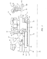
- FIG. 1 is a cross-sectional illustration of a shaft assembly 10 for a gas turbine engine.
- the shaft assembly 10 includes an engine shaft 12, one or more annular rotors 14, 16, 18, one or more annular stators 20, 22, and one or more annular stack nuts 24, 26.
- the shaft 12 is rotatable about an axial centerline 28.
- the shaft 12 includes an axially extending first shaft segment 30 and an axially extending threaded shaft segment 32 with a castellated end 34.
- the rotors may include a first rotor 14, a second rotor 16 and a third rotor 18.
- the first rotor 14 includes a clamping segment 36, a sealing segment 38 and a bridge segment 40.
- the clamping segment 36 extends axially between a first radial clamping surface 42 and a second radial clamping surface 44.
- the sealing segment 38 extends axially between a first end 46 and a radial distortion resistant contact sealing surface 48 at a second end.
- the bridge segment 40 extends radially between the clamping segment 36 and the sealing segment 38.
- the stators may include a first stator 20 and a second stator 22.
- the first stator 20 includes a radial contact sealing surface 50.
- the second stator 22 includes an annular seal 52 (e.g., a brush seal, a knife edge seal, a contact seal surface, a sacrificial seal surface, etc.).
- the stack nuts may include a first stack nut 24 and a second stack nut 26.
- FIG. 2 is a cross-sectional illustration of the first stack nut 24.
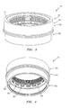
- FIGS. 3 and 4 are perspective illustrations of the first stack nut 24.
- the first stack nut 24 includes an annular base nut segment 54, an annular clamping nut segment 56, an annular torquing nut segment 58, and an annular seal land nut segment 60.
- the base nut segment 54 extends radially between a threaded nut bore 62 and an axial exterior nut surface 64.
- the base nut segment 54 extends axially between a first radial surface 66 and a second radial surface 68.
- the clamping nut segment 56 extends axially from the base nut segment 54, adjacent the first radial surface 66, to a distortion resistant load bearing surface 70.
- the load bearing surface 70 at least partially radially overlaps an intersection 72 between the clamping nut segment 56 and the base nut segment 54.
- the clamping nut segment 56 also extends radially between a radial inner, axial surface 74 and the exterior nut surface 64.
- an annular channel 76 extends into a corner between the radial inner, axial surface 74 and the first radial surface 66.
- the channel 76 may extend diagonally (e.g., along an axis acute to the centerline 28) such that a radial thickness of the clamping nut segment 56 decreases as the clamping nut segment 56 extends from the load bearing surface 70 towards the base nut segment 54.
- the channel 76 is disposed radially between a radial inner end 78 of the load bearing surface 70 and the base nut segment 54.
- the channel 76 may include an end 80 with a curved (e.g., arcuate, semi-circular, etc.) cross-sectional geometry.
- the torquing nut segment 58 extends axially from the base nut segment 54, adjacent the second radial surface 68, to a seal land nut segment contact surface 82.
- the torquing nut segment 58 extends radially between an inner castellated bore 84 and the exterior nut surface 64.
- the castellated bore 84 includes a plurality of radially inward extending protrusions 86 (e.g., splines).
- the protrusions 86 are sized and circumferentially arranged to mate with corresponding notches in a tool (not shown) for screwing the first stack nut 24 onto the threaded shaft segment 32 (see FIG. 1 ).
- Each protrusion 86 may include a circumferentially extending notch 88.
- the seal land nut segment 60 includes a seal segment 90 that extends axially from a torquing nut segment contact surface 92 to a channeled segment 94.
- the seal segment 90 extends radially between a radial inner, axial surface 96 and a radial outer, axial seal land surface 98.
- the channeled segment 94 includes a circumferentially extending channel 100.
- the torquing nut segment contact surface 92 is connected (e.g., welded) to the seal land nut segment contact surface 82.
- the second rotor 16 is disposed on the first shaft segment 30, and fixedly secured between the second stack nut 26 and a shaft shoulder (not shown).
- the third rotor 18 is disposed on and fixedly secured to the second rotor 16 and the second stack nut 26.
- the clamping segment 36 is disposed on the third rotor 18, and fixedly secured between the clamping segment 36 and a shaft shoulder (not shown).
- the threaded nut bore 62 is threaded onto the threaded shaft segment 32 such that the load bearing surface 70 exerts an axial clamp force against the second radial clamping surface 44.
- the radial contact sealing surface 50 contacts the distortion resistant contact sealing surface 48 forming a seal therebetween.
- the annular seal 52 engages the axial seal land surface forming a seal therebetween.
- An anti-rotation washer 102 may be arranged between the load bearing surface 70 and the second radial clamping surface 44 to prevent the first rotor 14 from rotating as the stack nut is threaded onto the shaft 12.
- a keyed washer 104 may be mated with the castellated bore 84 and the castellated end 34 of the threaded shaft segment 32 to prevent rotation of the first stack nut 24 during engine operation.
- a retaining ring 106 may be seated within the notches 88 to hold the keyed washer 104 in position.
- a damping ring 108 may be seated within the channel 100 to dampen vibrations within the first stack nut 24.
- the first stack nut 24 may be subjected to a thermal gradient.
- the thermal gradient may cause different regions of the first stack nut 24 to thermally expand at different rates.
- the segments of the first stack nut 24 are configured to thermally expand in a manner that may maintain a substantially uniform axial clamp force against the second radial clamping surface 44.
- the clamping nut segment 56 may thermally expand in a manner that maintains the load bearing surface 70 in a substantially perpendicular orientation relative to the shaft 12. Disruptive effects to the seal between the first rotor 14 and the first stator 20 caused by thermal expansion within the first stack nut 24 therefore may be reduced relative to prior art shaft assemblies.
- the first stack nut 24 may be configured such that the load bearing surface 70 cones towards or away from the first rotor 14 in order to increase or reduce the axial force against the second radial clamping surface 44.
- the seal land nut segment 60 may be formed integral with the torquing nut segment 58.
- the clamping nut segment 56 and/or the torquing nut segment 58 may be connected (e.g., welded) to the base nut segment 54.
- clamping nut segment 56, the torquing nut segment 58 and/or the seal land nut segment 60 may be omitted from the first stack nut 24.
Landscapes
- Engineering & Computer Science (AREA)
- Mechanical Engineering (AREA)
- General Engineering & Computer Science (AREA)
- Turbine Rotor Nozzle Sealing (AREA)
Claims (11)
- Wellenbaugruppe für ein Gasturbinentriebwerk, umfassend:eine Welle (12), die ein Gewindewellensegment (32) umfasst;einen ringförmigen Rotor (14), der an der Welle (12) angeordnet ist; undeine ringförmige Stapelmutter (24), umfassend
ein Basismuttersegment (54), das eine Gewindemutterbohrung (62) umfasst, die mit dem Gewindewellensegment (32) verbunden ist; und
ein Klemmmuttersegment (56), das sich axial von dem Basismuttersegment (54) zu einer Lasttragefläche (70) erstreckt und eine radiale Dicke umfasst, die abnimmt, je weiter sich das Klemmmuttersegment (56) von der Lasttragefläche (70) zum Basismuttersegment (54) erstreckt, wobei die Lasttragefläche (70) eine Kraft auf den ringförmigen Rotor (14) ausübt und den ringförmigen Rotor (14) an der Welle (12) sichert,
dadurch gekennzeichnet, dass:die ringförmige Stapelmutter (24) ferner einen ringförmigen Kanal (76) umfasst, der sich diagonal in eine radial innere axiale Fläche (74) des Klemmmuttersegments (56) und eine radiale Fläche (66) des Basismuttersegments (54) erstreckt. - Wellenbaugruppe nach Anspruch 1, wobei die Lasttragefläche (70) wenigstens teilweise einen Schnittpunkt (72) zwischen dem Klemmmuttersegment (56) und dem Basismuttersegment (54) radial überlagert.
- Wellenbaugruppe nach Anspruch 1 oder 2, wobei die Lasttragefläche (70) im Wesentlichen senkrecht zur Welle (12) bleibt, wenn die Temperatur der ringförmigen Stapelmutter (24) sich während des Triebwerkbetriebs ändert.
- Wellenbaugruppe nach einem der Ansprüche 1 bis 3, wobei der ringförmige Kanal (76) radial zwischen einem radialen inneren Ende (78) der Lasttragefläche (70) und dem Basismuttersegment (54) angeordnet ist.
- Wellenbaugruppe nach einem der vorangehenden Ansprüche, wobei der ringförmige Kanal (76) ein Ende (80) mit einer gekrümmten Querschnittgeometrie umfasst.
- Wellenbaugruppe nach einem der vorangehenden Ansprüche, wobei die ringförmige Stapelmutter (24) ferner ein Anzugsmuttersegment (58) umfasst, das eine innere mit Kronen versehene Bohrung (84) umfasst, und das Basismuttersegment (54) axial zwischen dem Klemmmuttersegment (56) und dem Anzugsmuttersegment (58) verbunden ist.
- Wellenbaugruppe nach einem der vorangehenden Ansprüche, ferner umfassend eine ringförmige Dichtung (52), die mit einem Dichtungsabsatzmuttersegment (60) der ringförmigen Stapelmutter (24) in Eingriff steht, wobei das Basismuttersegment (54) axial zwischen dem Klemmmuttersegment (56) und dem Dichtungsabsatzmuttersegment (60) verbunden ist.
- Wellenbaugruppe nach Anspruch 7, wobei die ringförmige Stapelmutter (24) ferner ein Anzugsmuttersegment (58) umfasst, das axial zwischen dem Basismuttersegment (54) und dem Dichtungsabsatzmuttersegment (60) verbunden ist, und das Anzugsmuttersegment (58) eine innere mit Kronen versehene Bohrung (84) umfasst.
- Wellenbaugruppe nach Anspruch 8, wobei die ringförmige Dichtung (52) in Eingriff mit einer axialen Dichtungsabsatzfläche (98) des Dichtungsabsatzmuttersegments (60) steht.
- Wellenbaugruppe nach Anspruch 8 oder 9, wobei die ringförmige Stapelmutter (24) ferner ein Klemmmuttersegment (56) umfasst, das sich axial vom Basismuttersegment (54) zur Lasttragefläche (70) erstreckt und eine radiale Dicke umfasst, die abnimmt, je weiter sich das Klemmmuttersegment (56) von der Lasttragefläche (70) zum Basismuttersegment (54) erstreckt.
- Wellenbaugruppe nach Anspruch 10, wobei die Lasttragefläche (70) wenigstens teilweise einen Schnittpunkt zwischen dem Klemmmuttersegment (56) und dem Basismuttersegment (54) radial überlagert.
Applications Claiming Priority (1)
| Application Number | Priority Date | Filing Date | Title |
|---|---|---|---|
| US13/267,539 US8932011B2 (en) | 2011-10-06 | 2011-10-06 | Shaft assembly for a gas turbine engine |
Publications (3)
| Publication Number | Publication Date |
|---|---|
| EP2639403A2 EP2639403A2 (de) | 2013-09-18 |
| EP2639403A3 EP2639403A3 (de) | 2013-12-11 |
| EP2639403B1 true EP2639403B1 (de) | 2015-05-27 |
Family
ID=47142923
Family Applications (1)
| Application Number | Title | Priority Date | Filing Date |
|---|---|---|---|
| EP12187480.4A Active EP2639403B1 (de) | 2011-10-06 | 2012-10-05 | Wellenanordnung für einen Gasturbinenmotor |
Country Status (2)
| Country | Link |
|---|---|
| US (1) | US8932011B2 (de) |
| EP (1) | EP2639403B1 (de) |
Families Citing this family (7)
| Publication number | Priority date | Publication date | Assignee | Title |
|---|---|---|---|---|
| US8875378B2 (en) * | 2011-11-07 | 2014-11-04 | United Technologies Corporation | Tie bolt employing differential thread |
| US10094277B2 (en) * | 2014-06-20 | 2018-10-09 | United Technologies Corporation | Gas turbine engine configured for modular assembly/disassembly and method for same |
| FR3068391B1 (fr) * | 2017-06-30 | 2020-07-17 | Safran Aircraft Engines | Ensemble pour module de turbomachine, module de turbomachine et turbomachine associes |
| US10598020B2 (en) * | 2018-01-05 | 2020-03-24 | United Technologies Corporation | Spanner nut centering feature |
| US10927709B2 (en) | 2018-06-05 | 2021-02-23 | Raytheon Technologies Corporation | Turbine bearing stack load bypass nut |
| US11719283B2 (en) * | 2019-04-09 | 2023-08-08 | Rolls-Royce North American Technologies, Inc. | Axially clamping rotating engine components |
| US11415062B2 (en) | 2020-11-18 | 2022-08-16 | Raytheon Technologies Corporation | Rotating sleeve controlling clearance of seal assembly of gas turbine engine |
Family Cites Families (23)
| Publication number | Priority date | Publication date | Assignee | Title |
|---|---|---|---|---|
| US3602535A (en) * | 1970-05-14 | 1971-08-31 | Gen Motors Corp | Shaft coupling |
| US3718957A (en) * | 1970-09-03 | 1973-03-06 | Avco Corp | Method of securing a threaded element in a high centrifugal force field |
| BE789470A (fr) * | 1971-09-30 | 1973-01-15 | Gen Electric | Dispositif de fixation et outil pour celui-ci |
| US3823553A (en) * | 1972-12-26 | 1974-07-16 | Gen Electric | Gas turbine with removable self contained power turbine module |
| US4611464A (en) * | 1984-05-02 | 1986-09-16 | United Technologies Corporation | Rotor assembly for a gas turbine engine and method of disassembly |
| GB2223083B (en) * | 1988-09-27 | 1993-01-06 | Pratt & Whitney Canada | Shaft coupling for gas turbine engine |
| US5220784A (en) * | 1991-06-27 | 1993-06-22 | Allied-Signal Inc. | Gas turbine engine module assembly |
| US5533863A (en) | 1993-03-26 | 1996-07-09 | Allied Signal Inc | Self positioning nut |
| US5580183A (en) * | 1994-04-29 | 1996-12-03 | United Technologies Corporation | Gas turbine engine spline arrangement |
| US5537814A (en) * | 1994-09-28 | 1996-07-23 | General Electric Company | High pressure gas generator rotor tie rod system for gas turbine engine |
| US5626347A (en) | 1994-09-29 | 1997-05-06 | Alliedsignal Inc. | Coning resistant face seal having a "U" shape |
| WO1997026475A1 (en) | 1996-01-19 | 1997-07-24 | Alliedsignal Inc. | Circumferential seal with ceramic rotor |
| US6375421B1 (en) * | 2000-01-31 | 2002-04-23 | General Electric Company | Piggyback rotor blisk |
| US6428272B1 (en) * | 2000-12-22 | 2002-08-06 | General Electric Company | Bolted joint for rotor disks and method of reducing thermal gradients therein |
| US7410173B2 (en) | 2003-05-01 | 2008-08-12 | Justak John F | Hydrodynamic brush seal |
| FR2857708B1 (fr) * | 2003-07-15 | 2005-09-23 | Snecma Moteurs | Dispositif perfectionne de fixation d'un arbre de moteur sur un support de palier |
| US7926260B2 (en) | 2006-07-05 | 2011-04-19 | United Technologies Corporation | Flexible shaft for gas turbine engine |
| US20090205341A1 (en) | 2008-02-20 | 2009-08-20 | Muldoon Marc J | Gas turbine engine with twin towershaft accessory gearbox |
| US8167314B2 (en) | 2009-03-31 | 2012-05-01 | United Technologies Corporation | Distortion resistant face seal counterface system |
| US20100303610A1 (en) | 2009-05-29 | 2010-12-02 | United Technologies Corporation | Cooled gas turbine stator assembly |
| US8186939B2 (en) * | 2009-08-25 | 2012-05-29 | Pratt & Whitney Canada Corp. | Turbine disc and retaining nut arrangement |
| US8650885B2 (en) | 2009-12-22 | 2014-02-18 | United Technologies Corporation | Retaining member for use with gas turbine engine shaft and method of assembly |
| US8517687B2 (en) | 2010-03-10 | 2013-08-27 | United Technologies Corporation | Gas turbine engine compressor and turbine section assembly utilizing tie shaft |
-
2011
- 2011-10-06 US US13/267,539 patent/US8932011B2/en active Active
-
2012
- 2012-10-05 EP EP12187480.4A patent/EP2639403B1/de active Active
Also Published As
| Publication number | Publication date |
|---|---|
| US8932011B2 (en) | 2015-01-13 |
| EP2639403A2 (de) | 2013-09-18 |
| EP2639403A3 (de) | 2013-12-11 |
| US20130089432A1 (en) | 2013-04-11 |
Similar Documents
| Publication | Publication Date | Title |
|---|---|---|
| EP2639403B1 (de) | Wellenanordnung für einen Gasturbinenmotor | |
| EP2372100B1 (de) | Startkohlenstoffsiegel | |
| US20180355761A1 (en) | Axially divided turbomachine inner ring | |
| JP5634715B2 (ja) | コンプライアントプレートシール組立体の製造方法 | |
| US7618234B2 (en) | Hook ring segment for a compressor vane | |
| EP3208502B1 (de) | Keramikdichtungskanal und -befestigung für rotierende welle | |
| US8534673B2 (en) | Inter stage seal housing having a replaceable wear strip | |
| JP6126342B2 (ja) | ガスタービンエンジン用のシャフトアッセンブリ | |
| US9127559B2 (en) | Diaphragm for turbomachines and method of manufacture | |
| WO2018041949A1 (en) | Axial bearing arrangement for a drive shaft of a centrifugal compressor | |
| EP3048343B1 (de) | Mehrstufige zwischenwellenringdichtung | |
| US20030063821A1 (en) | Bearing assembly and method | |
| US8147200B2 (en) | Turbine engine wheel | |
| EP3561240B1 (de) | Kohlenstoffdichtung | |
| EP3527801B1 (de) | Druckausgeglichene sekundärdichtung | |
| US7497658B2 (en) | Stacked reaction steam turbine stator assembly | |
| CN114402121B (zh) | 用于涡轮机的组合件 | |
| US12553347B2 (en) | Clamping composite assembly | |
| US10036474B2 (en) | Vented lift off seal assemblies | |
| KR20210002683A (ko) | 원심력에 최적화된 접촉면을 갖는 회전자 | |
| US20130071055A1 (en) | Fluid-riding device | |
| WO2016100212A1 (en) | Hydrodynamic seal assembly with interface control |
Legal Events
| Date | Code | Title | Description |
|---|---|---|---|
| PUAI | Public reference made under article 153(3) epc to a published international application that has entered the european phase |
Free format text: ORIGINAL CODE: 0009012 |
|
| AK | Designated contracting states |
Kind code of ref document: A2 Designated state(s): AL AT BE BG CH CY CZ DE DK EE ES FI FR GB GR HR HU IE IS IT LI LT LU LV MC MK MT NL NO PL PT RO RS SE SI SK SM TR |
|
| AX | Request for extension of the european patent |
Extension state: BA ME |
|
| PUAL | Search report despatched |
Free format text: ORIGINAL CODE: 0009013 |
|
| AK | Designated contracting states |
Kind code of ref document: A3 Designated state(s): AL AT BE BG CH CY CZ DE DK EE ES FI FR GB GR HR HU IE IS IT LI LT LU LV MC MK MT NL NO PL PT RO RS SE SI SK SM TR |
|
| AX | Request for extension of the european patent |
Extension state: BA ME |
|
| RIC1 | Information provided on ipc code assigned before grant |
Ipc: F01D 5/02 20060101AFI20131106BHEP Ipc: F01D 5/06 20060101ALI20131106BHEP |
|
| 17P | Request for examination filed |
Effective date: 20140605 |
|
| RBV | Designated contracting states (corrected) |
Designated state(s): AL AT BE BG CH CY CZ DE DK EE ES FI FR GB GR HR HU IE IS IT LI LT LU LV MC MK MT NL NO PL PT RO RS SE SI SK SM TR |
|
| GRAP | Despatch of communication of intention to grant a patent |
Free format text: ORIGINAL CODE: EPIDOSNIGR1 |
|
| INTG | Intention to grant announced |
Effective date: 20141211 |
|
| GRAS | Grant fee paid |
Free format text: ORIGINAL CODE: EPIDOSNIGR3 |
|
| GRAA | (expected) grant |
Free format text: ORIGINAL CODE: 0009210 |
|
| AK | Designated contracting states |
Kind code of ref document: B1 Designated state(s): AL AT BE BG CH CY CZ DE DK EE ES FI FR GB GR HR HU IE IS IT LI LT LU LV MC MK MT NL NO PL PT RO RS SE SI SK SM TR |
|
| REG | Reference to a national code |
Ref country code: GB Ref legal event code: FG4D |
|
| REG | Reference to a national code |
Ref country code: CH Ref legal event code: EP |
|
| REG | Reference to a national code |
Ref country code: AT Ref legal event code: REF Ref document number: 728980 Country of ref document: AT Kind code of ref document: T Effective date: 20150615 |
|
| REG | Reference to a national code |
Ref country code: IE Ref legal event code: FG4D |
|
| REG | Reference to a national code |
Ref country code: DE Ref legal event code: R096 Ref document number: 602012007539 Country of ref document: DE |
|
| REG | Reference to a national code |
Ref country code: AT Ref legal event code: MK05 Ref document number: 728980 Country of ref document: AT Kind code of ref document: T Effective date: 20150527 |
|
| REG | Reference to a national code |
Ref country code: LT Ref legal event code: MG4D |
|
| PG25 | Lapsed in a contracting state [announced via postgrant information from national office to epo] |
Ref country code: NO Free format text: LAPSE BECAUSE OF FAILURE TO SUBMIT A TRANSLATION OF THE DESCRIPTION OR TO PAY THE FEE WITHIN THE PRESCRIBED TIME-LIMIT Effective date: 20150827 Ref country code: LT Free format text: LAPSE BECAUSE OF FAILURE TO SUBMIT A TRANSLATION OF THE DESCRIPTION OR TO PAY THE FEE WITHIN THE PRESCRIBED TIME-LIMIT Effective date: 20150527 Ref country code: HR Free format text: LAPSE BECAUSE OF FAILURE TO SUBMIT A TRANSLATION OF THE DESCRIPTION OR TO PAY THE FEE WITHIN THE PRESCRIBED TIME-LIMIT Effective date: 20150527 Ref country code: PT Free format text: LAPSE BECAUSE OF FAILURE TO SUBMIT A TRANSLATION OF THE DESCRIPTION OR TO PAY THE FEE WITHIN THE PRESCRIBED TIME-LIMIT Effective date: 20150928 Ref country code: FI Free format text: LAPSE BECAUSE OF FAILURE TO SUBMIT A TRANSLATION OF THE DESCRIPTION OR TO PAY THE FEE WITHIN THE PRESCRIBED TIME-LIMIT Effective date: 20150527 Ref country code: ES Free format text: LAPSE BECAUSE OF FAILURE TO SUBMIT A TRANSLATION OF THE DESCRIPTION OR TO PAY THE FEE WITHIN THE PRESCRIBED TIME-LIMIT Effective date: 20150527 |
|
| REG | Reference to a national code |
Ref country code: NL Ref legal event code: MP Effective date: 20150527 |
|
| PG25 | Lapsed in a contracting state [announced via postgrant information from national office to epo] |
Ref country code: GR Free format text: LAPSE BECAUSE OF FAILURE TO SUBMIT A TRANSLATION OF THE DESCRIPTION OR TO PAY THE FEE WITHIN THE PRESCRIBED TIME-LIMIT Effective date: 20150828 Ref country code: AT Free format text: LAPSE BECAUSE OF FAILURE TO SUBMIT A TRANSLATION OF THE DESCRIPTION OR TO PAY THE FEE WITHIN THE PRESCRIBED TIME-LIMIT Effective date: 20150527 Ref country code: IS Free format text: LAPSE BECAUSE OF FAILURE TO SUBMIT A TRANSLATION OF THE DESCRIPTION OR TO PAY THE FEE WITHIN THE PRESCRIBED TIME-LIMIT Effective date: 20150927 Ref country code: LV Free format text: LAPSE BECAUSE OF FAILURE TO SUBMIT A TRANSLATION OF THE DESCRIPTION OR TO PAY THE FEE WITHIN THE PRESCRIBED TIME-LIMIT Effective date: 20150527 Ref country code: BG Free format text: LAPSE BECAUSE OF FAILURE TO SUBMIT A TRANSLATION OF THE DESCRIPTION OR TO PAY THE FEE WITHIN THE PRESCRIBED TIME-LIMIT Effective date: 20150827 Ref country code: RS Free format text: LAPSE BECAUSE OF FAILURE TO SUBMIT A TRANSLATION OF THE DESCRIPTION OR TO PAY THE FEE WITHIN THE PRESCRIBED TIME-LIMIT Effective date: 20150527 |
|
| PG25 | Lapsed in a contracting state [announced via postgrant information from national office to epo] |
Ref country code: DK Free format text: LAPSE BECAUSE OF FAILURE TO SUBMIT A TRANSLATION OF THE DESCRIPTION OR TO PAY THE FEE WITHIN THE PRESCRIBED TIME-LIMIT Effective date: 20150527 Ref country code: EE Free format text: LAPSE BECAUSE OF FAILURE TO SUBMIT A TRANSLATION OF THE DESCRIPTION OR TO PAY THE FEE WITHIN THE PRESCRIBED TIME-LIMIT Effective date: 20150527 |
|
| PG25 | Lapsed in a contracting state [announced via postgrant information from national office to epo] |
Ref country code: PL Free format text: LAPSE BECAUSE OF FAILURE TO SUBMIT A TRANSLATION OF THE DESCRIPTION OR TO PAY THE FEE WITHIN THE PRESCRIBED TIME-LIMIT Effective date: 20150527 Ref country code: SK Free format text: LAPSE BECAUSE OF FAILURE TO SUBMIT A TRANSLATION OF THE DESCRIPTION OR TO PAY THE FEE WITHIN THE PRESCRIBED TIME-LIMIT Effective date: 20150527 Ref country code: CZ Free format text: LAPSE BECAUSE OF FAILURE TO SUBMIT A TRANSLATION OF THE DESCRIPTION OR TO PAY THE FEE WITHIN THE PRESCRIBED TIME-LIMIT Effective date: 20150527 Ref country code: RO Free format text: LAPSE BECAUSE OF NON-PAYMENT OF DUE FEES Effective date: 20150527 |
|
| REG | Reference to a national code |
Ref country code: DE Ref legal event code: R097 Ref document number: 602012007539 Country of ref document: DE |
|
| PLBE | No opposition filed within time limit |
Free format text: ORIGINAL CODE: 0009261 |
|
| STAA | Information on the status of an ep patent application or granted ep patent |
Free format text: STATUS: NO OPPOSITION FILED WITHIN TIME LIMIT |
|
| PG25 | Lapsed in a contracting state [announced via postgrant information from national office to epo] |
Ref country code: IT Free format text: LAPSE BECAUSE OF FAILURE TO SUBMIT A TRANSLATION OF THE DESCRIPTION OR TO PAY THE FEE WITHIN THE PRESCRIBED TIME-LIMIT Effective date: 20150527 |
|
| 26N | No opposition filed |
Effective date: 20160301 |
|
| PG25 | Lapsed in a contracting state [announced via postgrant information from national office to epo] |
Ref country code: SI Free format text: LAPSE BECAUSE OF FAILURE TO SUBMIT A TRANSLATION OF THE DESCRIPTION OR TO PAY THE FEE WITHIN THE PRESCRIBED TIME-LIMIT Effective date: 20150527 Ref country code: LU Free format text: LAPSE BECAUSE OF FAILURE TO SUBMIT A TRANSLATION OF THE DESCRIPTION OR TO PAY THE FEE WITHIN THE PRESCRIBED TIME-LIMIT Effective date: 20151005 |
|
| REG | Reference to a national code |
Ref country code: CH Ref legal event code: PL |
|
| PG25 | Lapsed in a contracting state [announced via postgrant information from national office to epo] |
Ref country code: MC Free format text: LAPSE BECAUSE OF FAILURE TO SUBMIT A TRANSLATION OF THE DESCRIPTION OR TO PAY THE FEE WITHIN THE PRESCRIBED TIME-LIMIT Effective date: 20150527 |
|
| REG | Reference to a national code |
Ref country code: IE Ref legal event code: MM4A |
|
| PG25 | Lapsed in a contracting state [announced via postgrant information from national office to epo] |
Ref country code: CH Free format text: LAPSE BECAUSE OF NON-PAYMENT OF DUE FEES Effective date: 20151031 Ref country code: LI Free format text: LAPSE BECAUSE OF NON-PAYMENT OF DUE FEES Effective date: 20151031 |
|
| REG | Reference to a national code |
Ref country code: FR Ref legal event code: ST Effective date: 20160630 |
|
| PG25 | Lapsed in a contracting state [announced via postgrant information from national office to epo] |
Ref country code: FR Free format text: LAPSE BECAUSE OF NON-PAYMENT OF DUE FEES Effective date: 20151102 Ref country code: BE Free format text: LAPSE BECAUSE OF FAILURE TO SUBMIT A TRANSLATION OF THE DESCRIPTION OR TO PAY THE FEE WITHIN THE PRESCRIBED TIME-LIMIT Effective date: 20150527 |
|
| PG25 | Lapsed in a contracting state [announced via postgrant information from national office to epo] |
Ref country code: IE Free format text: LAPSE BECAUSE OF NON-PAYMENT OF DUE FEES Effective date: 20151005 |
|
| PG25 | Lapsed in a contracting state [announced via postgrant information from national office to epo] |
Ref country code: SM Free format text: LAPSE BECAUSE OF FAILURE TO SUBMIT A TRANSLATION OF THE DESCRIPTION OR TO PAY THE FEE WITHIN THE PRESCRIBED TIME-LIMIT Effective date: 20150527 Ref country code: HU Free format text: LAPSE BECAUSE OF FAILURE TO SUBMIT A TRANSLATION OF THE DESCRIPTION OR TO PAY THE FEE WITHIN THE PRESCRIBED TIME-LIMIT; INVALID AB INITIO Effective date: 20121005 |
|
| PG25 | Lapsed in a contracting state [announced via postgrant information from national office to epo] |
Ref country code: CY Free format text: LAPSE BECAUSE OF FAILURE TO SUBMIT A TRANSLATION OF THE DESCRIPTION OR TO PAY THE FEE WITHIN THE PRESCRIBED TIME-LIMIT Effective date: 20150527 Ref country code: NL Free format text: LAPSE BECAUSE OF FAILURE TO SUBMIT A TRANSLATION OF THE DESCRIPTION OR TO PAY THE FEE WITHIN THE PRESCRIBED TIME-LIMIT Effective date: 20150527 Ref country code: SE Free format text: LAPSE BECAUSE OF FAILURE TO SUBMIT A TRANSLATION OF THE DESCRIPTION OR TO PAY THE FEE WITHIN THE PRESCRIBED TIME-LIMIT Effective date: 20150527 |
|
| REG | Reference to a national code |
Ref country code: DE Ref legal event code: R082 Ref document number: 602012007539 Country of ref document: DE Representative=s name: SCHMITT-NILSON SCHRAUD WAIBEL WOHLFROM PATENTA, DE |
|
| REG | Reference to a national code |
Ref country code: DE Ref legal event code: R082 Ref document number: 602012007539 Country of ref document: DE Representative=s name: SCHMITT-NILSON SCHRAUD WAIBEL WOHLFROM PATENTA, DE Ref country code: DE Ref legal event code: R081 Ref document number: 602012007539 Country of ref document: DE Owner name: UNITED TECHNOLOGIES CORP. (N.D.GES.D. STAATES , US Free format text: FORMER OWNER: UNITED TECHNOLOGIES CORP., HARTFORD, CONN., US |
|
| PG25 | Lapsed in a contracting state [announced via postgrant information from national office to epo] |
Ref country code: MT Free format text: LAPSE BECAUSE OF FAILURE TO SUBMIT A TRANSLATION OF THE DESCRIPTION OR TO PAY THE FEE WITHIN THE PRESCRIBED TIME-LIMIT Effective date: 20150527 |
|
| PG25 | Lapsed in a contracting state [announced via postgrant information from national office to epo] |
Ref country code: MK Free format text: LAPSE BECAUSE OF FAILURE TO SUBMIT A TRANSLATION OF THE DESCRIPTION OR TO PAY THE FEE WITHIN THE PRESCRIBED TIME-LIMIT Effective date: 20150527 Ref country code: TR Free format text: LAPSE BECAUSE OF FAILURE TO SUBMIT A TRANSLATION OF THE DESCRIPTION OR TO PAY THE FEE WITHIN THE PRESCRIBED TIME-LIMIT Effective date: 20150527 |
|
| PG25 | Lapsed in a contracting state [announced via postgrant information from national office to epo] |
Ref country code: AL Free format text: LAPSE BECAUSE OF FAILURE TO SUBMIT A TRANSLATION OF THE DESCRIPTION OR TO PAY THE FEE WITHIN THE PRESCRIBED TIME-LIMIT Effective date: 20150527 |
|
| REG | Reference to a national code |
Ref country code: DE Ref legal event code: R081 Ref document number: 602012007539 Country of ref document: DE Owner name: RAYTHEON TECHNOLOGIES CORPORATION (N.D.GES.D.S, US Free format text: FORMER OWNER: UNITED TECHNOLOGIES CORP. (N.D.GES.D. STAATES DELAWARE), FARMINGTON, CONN., US Ref country code: DE Ref legal event code: R081 Ref document number: 602012007539 Country of ref document: DE Owner name: RTX CORPORATION (N.D.GES.D. STAATES DELAWARE),, US Free format text: FORMER OWNER: UNITED TECHNOLOGIES CORP. (N.D.GES.D. STAATES DELAWARE), FARMINGTON, CONN., US |
|
| P01 | Opt-out of the competence of the unified patent court (upc) registered |
Effective date: 20230520 |
|
| PGFP | Annual fee paid to national office [announced via postgrant information from national office to epo] |
Ref country code: GB Payment date: 20250923 Year of fee payment: 14 |
|
| REG | Reference to a national code |
Ref country code: DE Ref legal event code: R081 Ref document number: 602012007539 Country of ref document: DE Owner name: RTX CORPORATION (N.D.GES.D. STAATES DELAWARE),, US Free format text: FORMER OWNER: RAYTHEON TECHNOLOGIES CORPORATION (N.D.GES.D.STAATES DELAWARE), ARLINGTON, VA, US |
|
| PGFP | Annual fee paid to national office [announced via postgrant information from national office to epo] |
Ref country code: DE Payment date: 20250923 Year of fee payment: 14 |