EP2639489A2 - Appareil de montage à angle réglable - Google Patents
Appareil de montage à angle réglable Download PDFInfo
- Publication number
- EP2639489A2 EP2639489A2 EP12189528.8A EP12189528A EP2639489A2 EP 2639489 A2 EP2639489 A2 EP 2639489A2 EP 12189528 A EP12189528 A EP 12189528A EP 2639489 A2 EP2639489 A2 EP 2639489A2
- Authority
- EP
- European Patent Office
- Prior art keywords
- component
- mounting
- adjusting rod
- angle
- axis
- Prior art date
- Legal status (The legal status is an assumption and is not a legal conclusion. Google has not performed a legal analysis and makes no representation as to the accuracy of the status listed.)
- Withdrawn
Links
- 238000006073 displacement reaction Methods 0.000 claims description 13
- 239000000872 buffer Substances 0.000 claims description 5
- 230000000717 retained effect Effects 0.000 claims description 4
- 238000000034 method Methods 0.000 description 4
- 230000000694 effects Effects 0.000 description 3
- 230000015572 biosynthetic process Effects 0.000 description 2
- 230000035515 penetration Effects 0.000 description 2
- 238000012986 modification Methods 0.000 description 1
- 230000004048 modification Effects 0.000 description 1
- 239000004033 plastic Substances 0.000 description 1
Images




Classifications
-
- F—MECHANICAL ENGINEERING; LIGHTING; HEATING; WEAPONS; BLASTING
- F16—ENGINEERING ELEMENTS AND UNITS; GENERAL MEASURES FOR PRODUCING AND MAINTAINING EFFECTIVE FUNCTIONING OF MACHINES OR INSTALLATIONS; THERMAL INSULATION IN GENERAL
- F16M—FRAMES, CASINGS OR BEDS OF ENGINES, MACHINES OR APPARATUS, NOT SPECIFIC TO ENGINES, MACHINES OR APPARATUS PROVIDED FOR ELSEWHERE; STANDS; SUPPORTS
- F16M11/00—Stands or trestles as supports for apparatus or articles placed thereon ; Stands for scientific apparatus such as gravitational force meters
- F16M11/02—Heads
- F16M11/04—Means for attachment of apparatus; Means allowing adjustment of the apparatus relatively to the stand
- F16M11/06—Means for attachment of apparatus; Means allowing adjustment of the apparatus relatively to the stand allowing pivoting
- F16M11/08—Means for attachment of apparatus; Means allowing adjustment of the apparatus relatively to the stand allowing pivoting around a vertical axis, e.g. panoramic heads
-
- F—MECHANICAL ENGINEERING; LIGHTING; HEATING; WEAPONS; BLASTING
- F16—ENGINEERING ELEMENTS AND UNITS; GENERAL MEASURES FOR PRODUCING AND MAINTAINING EFFECTIVE FUNCTIONING OF MACHINES OR INSTALLATIONS; THERMAL INSULATION IN GENERAL
- F16M—FRAMES, CASINGS OR BEDS OF ENGINES, MACHINES OR APPARATUS, NOT SPECIFIC TO ENGINES, MACHINES OR APPARATUS PROVIDED FOR ELSEWHERE; STANDS; SUPPORTS
- F16M11/00—Stands or trestles as supports for apparatus or articles placed thereon ; Stands for scientific apparatus such as gravitational force meters
- F16M11/02—Heads
- F16M11/18—Heads with mechanism for moving the apparatus relatively to the stand
-
- F—MECHANICAL ENGINEERING; LIGHTING; HEATING; WEAPONS; BLASTING
- F16—ENGINEERING ELEMENTS AND UNITS; GENERAL MEASURES FOR PRODUCING AND MAINTAINING EFFECTIVE FUNCTIONING OF MACHINES OR INSTALLATIONS; THERMAL INSULATION IN GENERAL
- F16M—FRAMES, CASINGS OR BEDS OF ENGINES, MACHINES OR APPARATUS, NOT SPECIFIC TO ENGINES, MACHINES OR APPARATUS PROVIDED FOR ELSEWHERE; STANDS; SUPPORTS
- F16M11/00—Stands or trestles as supports for apparatus or articles placed thereon ; Stands for scientific apparatus such as gravitational force meters
- F16M11/20—Undercarriages with or without wheels
- F16M11/2007—Undercarriages with or without wheels comprising means allowing pivoting adjustment
- F16M11/2035—Undercarriages with or without wheels comprising means allowing pivoting adjustment in more than one direction
- F16M11/2057—Undercarriages with or without wheels comprising means allowing pivoting adjustment in more than one direction for tilting and rolling
-
- F—MECHANICAL ENGINEERING; LIGHTING; HEATING; WEAPONS; BLASTING
- F16—ENGINEERING ELEMENTS AND UNITS; GENERAL MEASURES FOR PRODUCING AND MAINTAINING EFFECTIVE FUNCTIONING OF MACHINES OR INSTALLATIONS; THERMAL INSULATION IN GENERAL
- F16M—FRAMES, CASINGS OR BEDS OF ENGINES, MACHINES OR APPARATUS, NOT SPECIFIC TO ENGINES, MACHINES OR APPARATUS PROVIDED FOR ELSEWHERE; STANDS; SUPPORTS
- F16M13/00—Other supports for positioning apparatus or articles; Means for steadying hand-held apparatus or articles
- F16M13/02—Other supports for positioning apparatus or articles; Means for steadying hand-held apparatus or articles for supporting on, or attaching to, an object, e.g. tree, gate, window-frame, cycle
Definitions
- the present invention relates to an angle-adjustable mounting apparatus, more particularly to an angle-adjustable mounting apparatus which may be adjusted with precision and ease.
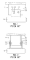
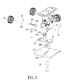
- a conventional mounting apparatus 11 is adapted for mounting an electronic device 13 to a fixed object, such as a ceiling 12.
- the mounting apparatus 11 includes a first mounting device 111 which is to be fixed to the ceiling 12, a second mounting device 113 which is for mounting the electronic device 13 and which has two lateral wings disposed at two sides of the first mounting device 111, and two pins 112 which are respectively disposed through the two lateral wings of the second mounting device 113 and the two sides of the first mounting device 111.
- the second mounting device 113 is pivotable relative to the first mounting device 111 about the pins 112.
- the two lateral wings of the second mounting device 113 are respectively formed with two curved limiting slots 114 therethrough.
- the mounting apparatus 11 further includes two bolts 115 which extend through a corresponding one of the limiting slots 114 and which engage threadedly and respectively the two sides of the first mounting device 111. Each of the bolts 115 is operable to screw in and out.
- the bolts 115 When the bolts 115 are screwed to move toward the first mounting device 111 (i.e., screw-in), the bolts 115 force the second mounting device 113 to press tightly the first mounting device 111 so as to fasten the second mounting device 113 to the first mounting device 111.
- the second mounting device 113 When the bolts 115 are screwed to move away from the first mounting device 111 (i.e., screw-out), the second mounting device 113 ceases to press tightly the first mounting device 111, such that assembly of the second mounting device 113 and the electronic device 13 may pivot relative to the first mounting device 111 within an angle limited by the curved limiting slots 114.
- the bolts 115 are screwed to force the second mounting device 113 to press the first mounting device 111, such that the second mounting device 113 is fastened to the first mounting device 111 once again. An effect of adjusting the angle of the electronic device 13 is thus achieved.
- the conventional mounting apparatus 11 has the following drawbacks when adjusting the angle of the electronic device 13 relative to the ceiling 12.
- each of the bolts 115 must be screwed respectively for forcing the second mounting device 113 to press the first mounting device 111 so as to fasten the second mounting device 113 to the first mounting device 111.
- the angle of the electronic device 13 after fastening the secondmounting device 113 to the first mounting device 111 often deviates from the desired angle, such that the angle of the electronic device 13 may not be adjusted precisely.
- an object of the present invention is to provide an angle-adjustable mounting apparatus which may be adjusted with precision and ease.
- the angle-adjustable mounting apparatus of the present invention is for mounting a second object to a first object.
- the angle-adjustable mounting apparatus comprises a first mounting device to be coupled to the first object, a second mounting device to be coupled to the second object, and a first pivot-control unit.
- the second mounting device is connected pivotally to the first mounting device and is pivotable relative to the first mounting device about a first axis.
- the first pivot-control unit includes a first component provided at the first mounting device and a second component provided at the second mounting device. The second component abuts against and is rotatable relative to the first component to enable the second mounting device to pivot relative to the first mounting device about the first axis.
- the first pivot-control unit further includes a first adjusting rod coupled to the second component and operable to drive the second component so that assembly of the second component and the second mounting device pivots relative to the first component.
- the second component is formed with a first threaded hole therethrough.
- the first threaded hole has a hole axis that is not parallel to the first axis.
- the first adjusting rod is a threaded rod which is coupled rotatably to the second mounting device for rotation about a rod axis of the first adjusting rod and which threadedly engages the first threaded hole. Rotation of the first adjusting rod relative to the second mounting device results in displacement of the first adjusting rod along the first threaded hole and pivoting of the assembly of the second component and the second mounting device relative to the first component.
- the socket component receives rotatably the plug component and has an inner socket wall surface that abuts against the curved surface of the socket component.
- the first mounting device includes a first mounting part, a second mounting part, and a second pivot-control unit.
- the first mounting part is to be coupled to the first object.
- the second mounting part is connected pivotally to the first mounting part and is pivotable relative to the first mounting part about a second axis that is perpendicular to the first axis.
- the second mounting device is connected pivotally to the second mounting part.
- the second pivot-control unit includes a third component provided at the first mounting part and a fourth component provided at the second mounting part. The fourth component abuts against and is rotatable relative to the third component to enable the second mounting part to pivot relative to the first mounting part about the second axis.
- the second pivot-control unit further includes a second adjusting rod coupled to the third component and operable to drive the third component so that assembly of the fourth component and the second mounting part pivots relative to the third component.
- the third component is formed with a second threaded hole therethrough.
- the second threaded hole has a hole axis that is not parallel to the second axis.
- the second adjusting rod is a threaded rod which is coupled rotatably to the first mounting part for rotation about a rod axis of the second adjusting rod and which threadedly engages the second threaded hole. Rotation of the second adjusting rod relative to the first mounting part results in displacement of the third component along the second adjusting rod and pivoting of the assembly of the fourth component and the second mounting part relative to the third component.
- one of the third and fourth components is a plug component with a curved surface
- the other one of the third and fourth components is a socket component that receives rotatably the plug component and that has an inner socket wall surface that abuts against the curved surface.
- the second mounting device includes a first connection part, a second connection part, and a third pivot-control unit.
- the first connection part is connected pivotally to the second mounting part.
- the second connection part is to be connected to the second object and is retained pivotally on the first connection part so as to be pivotable relative to the first connection part about a third axis perpendicular to the first and second axes.
- the third pivot-control unit includes an adjusting base and a third adjusting rod.
- the adjusting base is provided on the second connection part and is formed with a third threaded hole therethrough.
- the third threaded hole has a hole axis that is not parallel to the third axis.
- the third adjusting rod is a threaded rod coupled rotatably to the first connection part for rotation about a rod axis of the third adjusting rod.
- the third adjusting rod threadedly engages the third threaded hole. Rotation of the third adjusting rod relative to the first connection part results in displacement of the adjusting base along the third adjusting rod and pivoting of the second connection part relative to the first connection part.
- Effects of the present invention reside in that the first and second mounting devices are to be coupled respectively to the first and second objects, and the second mounting device is connected pivotally to the first mounting device, such that by means of cooperative designs, such as pivotal connection between the first and second mounting devices, rotation of the first adjusting rod, and linear displacement between the second component and the first adjusting rod, an angle between the first and second objects may be adjusted with precision and ease.
- a first preferred embodiment of an angle-adjustable mounting apparatus is for mounting a second object, such as a base of a projector (not shown), to a first object, such as a telescopic rod fixed to a wall (not shown).
- Components of the angle-adjustable mounting apparatus are pivotable about a first axis (X), a second axis (Y) and a third axis (Z) which are perpendicular to each other such that a relative position of the second object with respect to the first object may be adjusted in three directions.
- Pivoting of the components of the angle-adjustable mounting apparatus about the first axis (X) is illustrated hereinafter.
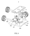
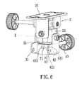
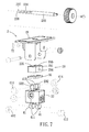
- the first preferred embodiment of the angle-adjustable mounting apparatus comprises a first mounting device 2, a second mounting device 3, and a first pivot mounting unit 4.
- the first mounting device 2 is to be coupled to the first object.
- the second mounting device 3 is to be coupled to the second object.
- the secondmounting device 3 is connected pivotally to the first mounting device 2 and is pivotable relative to the first mounting device 2 about a first axis (X).
- the first pivot-control unit 4 includes a first component 41 provided at the first mounting device 2 and a second component 42 provided at the second mounting device 3.
- the second component 42 abuts against and is rotatable relative to the first component 41 to enable the second mounting device 2 to pivot relative to the first mounting device 3 about the first axis (X).
- the first pivot-control unit 4 further includes a first adjusting rod 43 coupled to the second component 42 and operable to drive the second component 42 so that assembly of the second component 42 and the second mounting device 3 pivots relative to the first component 41.
- the second component 42 is formed with a first threaded hole 421 therethrough.
- the first threaded hole 421 has a hole axis that is not parallel to the first axis (X). In this embodiment, the hole axis is perpendicular to the first axis (X).
- an extension direction of the hole axis of the first threaded hole 421 is not limited herein, as long as the hole axis of the first threaded hole 421 is not parallel to the first axis (X).
- the first adjusting rod 43 is a threaded rod which is coupled rotatably to the second mounting device 3 for rotation about a rod axis of the first adjusting rod 43 and which threadedly engages the first threaded hole 421. Rotation of the first adjusting rod 43 relative to the second mounting device 3 results in displacement of the first adjusting rod 43 along the first threaded hole 421 and pivoting of the assembly of the second component 42 and the second mounting device 3 relative to the first component 2.
- the first component 41 is provided with two plug components with curved surfaces, and is formed on one side of the first mounting device 2 adjacent to the second mounting device 3.
- the number of the plug components of the first component 41 is not limited herein, and may be one, three, or more than three. More specifically, the plug components are substantially cylindrical in shape. However, the shapes of the plug components are not limited herein, and may be spherical or other shapes.
- the second component 42 is provided with two socket components 422 that are formed perpendicularly through the second component 42, that receive rotatably the plug components, and that have inner socket wall surfaces that abut against the curved surfaces of the plug components.
- socket components 422 is not limited to penetration through the second component 42, and the socket components 422 are merely required to be formed in one side of the second component 42 proximate to the first mounting device 2 and to receive rotatably the plug components.
- the number of the socket components 422 of the second component 42 is not limited to two, and may correspond to the number of the plug components of the first component 41 to be one, three, or more than three.
- the first adjusting rod 43 has a first large-diameter section 431, a first small-diameter section 432 which is located at a distal end of the first large-diameter section 431 and which has a diameter smaller than that of the first large-diameter section 431, and a first annular slot 433 formed in the first small-diameter section 432.
- the first small-diameter section 432 of the first adjusting rod 43 extends through one part of the second mounting device 3.
- a hole diameter of said one part of the second mounting device 3 through which the first small-diameter section 432 extends is larger than a diameter of the first small-diameter section 432 and is smaller than that of the first large-diameter section 431.
- the angle-adjustable mounting apparatus further comprises an E-shaped first engaging ring 71 for engaging the first annular slot 433 in a manner that a section of said one part of the second mounting device 3 is sandwichedbetween the first large-diameter section 431 and the first engaging ring 71. Therefore, the first adjusting rod 43 may not displace relative to the second mounting device 3 when operated to rotate.
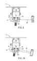
- the secondmounting device 3 brings the second object coupled thereto to pivot relative to the first object.
- the second component 42 rotates relative to the first component 41 as a result of the hole axis of the first threaded hole 421 being maintained parallel to the rod axis of the first adjusting rod 43.
- the second component 42 may pivot smoothly and not rotate idly as a result of the inner socket wall surfaces of the socket components 422 abutting against the curved surfaces of the plug components.
- each of the socket components 422 abuts against diametrically opposite parts of the curved surface of a respective one of the plug components, such that the second component 42 may not rotate idly as the first adjusting rod 34 is operated in an opposite direction.
- a contact relation between the inner socket wall surfaces and the curved surfaces is not limited to the disclosure herein.
- Pivoting of the components of the angle-adjustable mounting apparatus about the first axis (Y) is illustrated hereinafter.
- the first mounting device 2 includes a first mounting part 21, a second mounting part 22, and a second pivot-control unit 23.
- the first mounting part 21 is to be coupled to the first object.
- the second mounting part 22 is disposed between the first mounting part 21 and the second mounting device 3, is connected pivotally to the first mounting part 21 and is pivotable relative to the first mounting part 21 about a second axis (Y) that is perpendicular to the first axis (X).
- the secondmounting device 3 is connected pivotally to the second mounting part 22.
- the second pivot-control unit 23 includes a third component 231 provided at the first mounting part 21 and a fourth component 232 provided at the second mounting part 22.
- the fourth component 232 abuts against and is rotatable relative to the third component 231 to enable the second mounting part 22 to pivot relative to the first mounting part 21 about the second axis (Y).
- the second pivot-control unit 23 further includes a second adjusting rod 233 coupled to the third component 231 and operable to drive the third component 231 so that assembly of the fourth component 232 and the second mounting part 22 pivots relative to the third component 231.
- the third component 231 is formed with a second threaded hole 234 therethrough.
- the second threaded hole 234 has a hole axis that is not parallel to the second axis (Y).
- the hole axis of the second threaded hole 234 is perpendicular to the second axis (Y).
- an extension direction of the hole axis of the second threaded hole 234 is not limited herein, as long as the hole axis of the second threaded hole 234 is not parallel to the second axis (Y).
- the second adjusting rod 233 is a threaded rod which is coupled rotatably to the first mounting part 21 for rotation about a rod axis of the second adjusting rod 233 and which threadedly engages the second threaded hole 234. Rotation of the second adjusting rod 233 relative to the first mounting part 21 results in displacement of the third component 231 along the second adjusting rod 233 and pivoting of the assembly of the fourth component 232 and the second mounting part 22 relative to the third component 231.
- the fourth component 232 is provided with two plug components with curved surfaces, and is formed on one side of the second mounting part 22 adjacent to the first mounting part 21.
- the number of the plug components of the fourth component 232 is not limited herein, and may be one, three, or more than three. More specifically, the plug components are substantially cylindrical in shape. However, the shapes of the plug components are not limited herein, and may be spherical or other shapes.
- the third component 231 is provided with two socket components 235 that are formed perpendicularly through the third component 231, that receive rotatably the plug components of the fourth component 232, and that have inner socket wall surfaces that abut against the curved surfaces of the plug components.
- socket components 235 is not limited to penetration through the third component 231, and the socket components 235 are merely required to be formed in one side of the third component 231 proximate to the second mounting part 22 and to receive rotatably the plug components of the fourth component 232.
- the number of the socket components 235 of the third component 231 is not limited to two, and may correspond to the number of the plug components of the fourth component 232 to be one, three, or more than three.
- the second adjusting rod 233 has a second large-diameter section 236, a second small-diameter section 237 which is located at a distal end of the second large-diameter section 236 and which has a diameter smaller than that of the second large-diameter section 236, and a second annular slot 238 formed in the second small-diameter section 237.
- the second small-diameter section 237 of the second adjusting rod 233 extends through the first mounting part 21.
- a hole diameter of the first mounting part 21 through which the second small-diameter section 237 extends is larger than a diameter of the second small-diameter section 237 and is smaller than that of the second large-diameter section 236.
- the angle-adjustable mounting apparatus further comprises an E-shaped second engaging ring 72 for engaging the second annular slot 238 in a manner that a section of the first mounting part 21 is sandwiched between the second large-diameter section 236 and the second engaging ring 72. Therefore, the second adjusting rod 233 may not displace relative to the first mounting part 21 when operated to rotate.
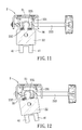
- the fourth component 232 abuts against and rotates relative to the third component 231 to enable the assembly of the fourth component 232 and the second mounting part 22 to pivot relative to the first mounting part 21 about the second axis (Y).
- the second mounting part 22 by means of the second mounting device 3 being connected pivotally to the second mounting part 22, brings the second object coupled to the second mounting device 3 to pivot relative to the first object.
- the fourth component 232 may pivot smoothly and not rotate idly as a result of the inner socket wall surfaces of the socket components 235 of the third component 231 abutting against the curved surfaces of the plug components of the fourth component 232.
- the inner socket wall surface of each of the socket components 235 abuts against diametrically opposite parts of the curved surface of a respective one of the plug components of the fourth component 232, such that the fourth component 232 may not rotate idly as the second adjusting rod 233 is operated in an opposite direction.
- a contact relation between the inner socket wall surfaces of the socket components 235 and the curved surfaces of the plug components of the fourth component 232 is not limited to the disclosure herein.
- Pivoting of the components of the angle-adjustable mounting apparatus about the third axis (Z) is illustrated hereinafter.
- the second mounting device 3 includes a first connection part 31, a second connection part 32, and a third pivot-control unit 33.
- the first connection part 31 is connected pivotally to the second mounting part 22 of the first mounting device 2.
- the aforementioned one part of the second mounting device 3 through which the first small-diameter section 432 of the first adjusting rod 43 extends is the first connection part 31 of the second mounting device 3.
- the second connection part 32 is to be connected to the second object and is retained pivotally on the first connection part 31 so as to be pivotable relative to the first connection part 31 about the third axis (Z) which is perpendicular to the first and second axes (X and Y) and which passes through the first connection part 31.
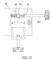
- the third pivot-control unit 33 includes an adjusting base 331 and a third adjusting rod 332.
- the adjusting base 331 is provided rotatably on the second connection part 32 and is formed with a third threaded hole 333 therethrough.
- the third threaded hole 333 has a hole axis that is not parallel to the third axis (Z).
- the hole axis of the third threaded hole 333 is perpendicular to the third axis (Z) and is parallel to a surface of the second connection part 32.
- an extension direction of the hole axis of the third threaded hole 333 is not limited herein, as long as the hole axis is not parallel to the third axis (Z).
- the third adjusting rod 332 is a threaded rod coupled rotatably to the first connection part 31 for rotation about a rod axis of the third adjusting rod 332.
- the third adjusting rod 332 threadedly engages the third threaded hole 333 of the adjusting base 331. Rotation of the third adjusting rod 332 relative to the first connection part 31 results in displacement of the adjusting base 331 along the third adjusting rod 332 and pivoting of the second connection part 32 relative to the first connection part 31.
- the second connection part 32 is movable relative to the adjusting base 331 on a plane perpendicular to the third axis (Z).
- the second connection part 32 is formed with a longitudinal slot 321.
- the adjusting base 331 is provided rotatably on the second connection part 32 in a manner of extending through the longitudinal slot 321, and the second connection part 32 is movable relative to the adjusting base 331 along the longitudinal slot 321.
- the third adjusting rod 332 has a third large-diameter section 334, a third small-diameter section 335 which is located at a distal end of the third large-diameter section 334 and which has a diameter smaller than that of the third large-diameter section 334, and a third annular slot 336 formed in the third small-diameter section 335.
- the third small-diameter section 335 of the third adjusting rod 332 extends through the first connection part 31.
- a hole diameter of the first connection part 31 through which the third small-diameter section 335 extends is larger than a diameter of the third small-diameter section 335 and is smaller than that of the third large-diameter section 334.
- the angle-adjustable mounting apparatus further comprises an E-shaped third engaging ring 73 for engaging the third annular slot 336 in a manner that a section of the first connection part 31 is sandwiched between the third large-diameter section 334 and the third engaging ring 73. Therefore, the third adjusting rod 332 may not displace relative to the first connection part 31 when operated to rotate.
- the second connection part 32 since the second connection part 32 is movable relative to the adjusting base 331 in combination with a bolt along the longitudinal slot 321 (see Figure 3 ), the second connection part 32 may pivot relative to the first connection part 31 about the third axis (Z) and move relative to the adjusting base 331 at the same time. That is, relative distance between the first connection part 31 and the adjusting base 331 is slightly variable for smooth pivoting of the second connection part 32 relative to the first connection part 31.
- first axis (X), the second axis (Y) and the third axis (Z) are independent with respect to each other, and pass through the second mounting part 22, the first mounting part 21 and the first connection part 31, respectively, when assembly of the second mounting part 22 and the first connection part 31 pivots as a result of the second adjusting rod 233 being operated, the first axis (X) and the third axis (Z) are displaced as well. Further, when the first connection part 31 pivots as a result of the first adjusting rod 43 being operated, the third axis (Z) is displaced as well.
- each of the plug components of the first component 41 includes a plug body 411 and a resilient cover 412 that covers the plug body 411.
- Each of the plug components of the fourth component 232 includes a plug body 413 and a resilient cover 414 that covers the plug body 413.
- the resilient covers 412 and 414 may be made of plastic or rubber.
- Each of the resilient covers 412 and 414 may provide better contacting effects for the inner socket wall surfaces of a respective one of the socket components 422 of the second component 42 and the socket components 235 of the third component 231 to abut against the curved surfaces of a corresponding one of the plug components of the first and fourth components 41 and 232, when the socket components 422 and 235 receive rotatably and respectively the plug components of the first and fourth components 41 and 232.
- the inner socket wall surfaces of the socket components 422 and 235 may still smoothly abut against the curved surfaces of the plug components, and noise resulting from abutment between the inner socket wall surfaces and the curved surfaces may be reduced.
- the resilient covers 412 and 414 tightly abut against the inner socket wall surfaces of a respective one of the socket components 422 and 235, so as to assist in keeping the angle-adjustable mounting apparatus steady when the first axis (X), the second axis (Y) and the third axis (Z) are not operated to rotate. Therefore, an angle between the first and second objects may be prevented from being changed when the angle-adjustable mounting apparatus is vibrated (such as vibration resulting from operation of mechanical components of the second object).
- the angle-adjustable mounting apparatus further comprises a resilient first buffer 35 disposed between the second mounting part 22 and the second component 42 for preventing the second component 42 from bumping against the second mounting part 22 as the second component 42 rotates, and a resilient second buffer 36 disposed between the second mounting part 22 and the third component 231 for preventing the second mounting part 22 from bumping against the third component 231 as the second mounting part 22 rotates.
- the first and second buffers 35 and 36 are rubber pads.
- one of the first and second connection parts 31 or 32 has a limit slot 811 and the other one of the first and second connection parts 32 or 31 has a limit protrusion 82 that cooperates with the limit slot 811 to limit angular rotation of the second connection part 32 relative to the first connection part 31.
- the angle-adjustable mounting apparatus further comprises a limit board 81 which is fixed to one side of the first connection part 31 adjacent to the second connection part 32 and which is formed with the curved limit slot 811.
- the limit protrusion 82 is fixed to the second connection part 32, and is movable relative to the limit board 81 along the limit slot 811.
- the limit protrusion 82 is brought to pivot about the third axis (Z) and to be limited by a curve length of the limit slot 811 such that the angular rotation of the second connection part 32 relative to the first connection part 31 is limited by the curve length of the limit slot 811. In this way, damage resulting from excessive angular rotation of the second connection part 32 relative to the first connection part 31 may be prevented.
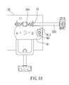
- the second preferred embodiment is substantially identical to the first preferred embodiment, but differs in the configuration that the angle-adjustable mounting apparatus further comprises a resilient unit 6 including a first spring 61, a second spring 62 and a third spring 63.
- the first spring 61 is sleeved on the first adjusting rod 43 and has two opposite ends acting on the second component 42 and the first connection part 31 of the second mounting device 3, respectively.
- the second spring 62 is sleeved on the second adjusting rod 233 and has two opposite ends acting on the third component 231 and the first mounting part 21, respectively.
- the third spring 63 is sleeved on the third adjusting rod 332 and has two opposite ends acting on the adjusting base 331 and the first connection part 31.
- Each of the first spring 61, the second spring 62 and the third spring 63 applies a force to a respective one of the second component 42, the third component 231 and the adjusting base 331 along a corresponding one of the first, second and third adjusting rods 43, 233 and 332, such that internal threads of the second component 42, the third component 231 and the adjusting base 331 engage tightly and respectively threads of the first, second and third adjusting rods 43, 233 and 332.
- a user may not feel idle rotation of the angle-adjustable mounting apparatus as a result of the threads not engaging tightly the internal threads.
- the angle between the second object and the first object may be adjusted with precision and ease by means of arrangements of the components of the angle-adjustable mounting apparatus in a manner that rotation of the first, second and third adjusting rods 43, 233 and 332 results in pivoting of the second mounting device 3, the second mounting part 22 and the second connection part 32 about a respective one of the first, second and third axes (X, Y and Z) which are perpendicular to each other.
Landscapes
- Engineering & Computer Science (AREA)
- General Engineering & Computer Science (AREA)
- Mechanical Engineering (AREA)
- Pivots And Pivotal Connections (AREA)
Applications Claiming Priority (1)
| Application Number | Priority Date | Filing Date | Title |
|---|---|---|---|
| TW101204856U TWM434423U (en) | 2012-03-16 | 2012-03-16 | Angle-adjustable support |
Publications (1)
| Publication Number | Publication Date |
|---|---|
| EP2639489A2 true EP2639489A2 (fr) | 2013-09-18 |
Family
ID=46882755
Family Applications (1)
| Application Number | Title | Priority Date | Filing Date |
|---|---|---|---|
| EP12189528.8A Withdrawn EP2639489A2 (fr) | 2012-03-16 | 2012-10-23 | Appareil de montage à angle réglable |
Country Status (3)
| Country | Link |
|---|---|
| US (1) | US8757564B2 (fr) |
| EP (1) | EP2639489A2 (fr) |
| TW (1) | TWM434423U (fr) |
Cited By (2)
| Publication number | Priority date | Publication date | Assignee | Title |
|---|---|---|---|---|
| EP2947370A1 (fr) * | 2014-05-20 | 2015-11-25 | Rosemount Aerospace Inc. | Appareil de montage d'écran |
| US20160018055A1 (en) * | 2014-07-15 | 2016-01-21 | Ming-Hsien Huang | Adjusting apparatus |
Families Citing this family (7)
| Publication number | Priority date | Publication date | Assignee | Title |
|---|---|---|---|---|
| CN102608843B (zh) * | 2012-04-16 | 2014-11-05 | 威宝摄影器材有限公司 | 一种可快速拉伸的反折叠相机三脚架 |
| US20140165757A1 (en) * | 2012-12-14 | 2014-06-19 | Moog Inc. | Positioning device |
| TW201433730A (zh) * | 2013-02-20 | 2014-09-01 | Hon Hai Prec Ind Co Ltd | 旋轉雲台 |
| US9382015B2 (en) * | 2014-01-16 | 2016-07-05 | Rosemount Aerospace Inc. | Single aisle mount |
| TWM497730U (zh) | 2014-07-10 | 2015-03-21 | Syncmold Entpr Corp | 可調式吊掛裝置 |
| CN109469674B (zh) * | 2018-12-24 | 2023-09-15 | 深圳市光祥科技股份有限公司 | 插销式连接装置 |
| US12644560B2 (en) * | 2023-06-09 | 2026-06-02 | Really Right Stuff, Llc | Support for a clamp with improved structure |
Family Cites Families (19)
| Publication number | Priority date | Publication date | Assignee | Title |
|---|---|---|---|---|
| US3128982A (en) * | 1964-04-14 | Tripod head | ||
| US2180214A (en) * | 1938-03-03 | 1939-11-14 | Rapp Charles | Universal head |
| US2318633A (en) * | 1940-08-13 | 1943-05-11 | Park J Ries | Instrument mounting device |
| US2500048A (en) * | 1947-01-30 | 1950-03-07 | Eastman Kodak Co | Clamping device |
| CA1090757A (fr) * | 1978-05-05 | 1980-12-02 | Gerd Kurz | No translation available |
| US4225105A (en) * | 1978-10-31 | 1980-09-30 | Mitsuwa Photo Industry Co. Ltd. | Tilt mounting |
| US4249817A (en) * | 1979-05-21 | 1981-02-10 | Blau Robert E | Adjustable head for tripods |
| US4763151A (en) * | 1987-05-14 | 1988-08-09 | Klinger Joseph K | Universal tripod head |
| US6349905B1 (en) * | 1998-01-22 | 2002-02-26 | James Everett Mills | Versatile portable apparatus for supporting cameras, spotting scopes and other supportable devices |
| US6116554A (en) * | 1999-09-15 | 2000-09-12 | Wei; David | Tripod |
| US20020179786A1 (en) * | 2001-04-17 | 2002-12-05 | Wei Jie Zheng | ZWJ-angle-adjustment |
| US6663298B2 (en) * | 2002-02-07 | 2003-12-16 | Todd Gregory Haney | Hand held counter balance and shock absorber camera mount |
| US7270509B2 (en) * | 2004-03-22 | 2007-09-18 | Universal Metal Products, Inc. | Fastener assembly |
| ITPD20050186A1 (it) * | 2005-06-21 | 2006-12-22 | Lino Manfrotto & Co Spa | Dispositivo di attacco rapido per attrezzature video e fotografiche |
| US7303171B1 (en) * | 2006-11-21 | 2007-12-04 | Supa Technology Co., Ltd. | Adjustable fixing mount |
| US8267361B1 (en) * | 2007-10-18 | 2012-09-18 | Acratech, Inc. | Attachment to a long lens support device which functions as both a ball head and a gimble head |
| CN101598886B (zh) * | 2009-07-07 | 2010-12-29 | 刘昊 | 四轴摄影云台 |
| US20110297809A1 (en) * | 2010-06-08 | 2011-12-08 | Bouissiere Michael F | Projector mount with micro adjustment |
| TW201211438A (en) * | 2010-09-02 | 2012-03-16 | ming-xian Huang | Supporting device allowing fine adjustment of rotation angle and tilt degree |
-
2012
- 2012-03-16 TW TW101204856U patent/TWM434423U/zh not_active IP Right Cessation
- 2012-07-30 US US13/561,850 patent/US8757564B2/en active Active
- 2012-10-23 EP EP12189528.8A patent/EP2639489A2/fr not_active Withdrawn
Non-Patent Citations (1)
| Title |
|---|
| None |
Cited By (5)
| Publication number | Priority date | Publication date | Assignee | Title |
|---|---|---|---|---|
| EP2947370A1 (fr) * | 2014-05-20 | 2015-11-25 | Rosemount Aerospace Inc. | Appareil de montage d'écran |
| US9446854B2 (en) | 2014-05-20 | 2016-09-20 | Rosemount Aerospace, Inc. | Display mounting apparatus |
| US9752722B2 (en) | 2014-05-20 | 2017-09-05 | Rosemount Aerospace, Inc. | Display mounting apparatus |
| US20160018055A1 (en) * | 2014-07-15 | 2016-01-21 | Ming-Hsien Huang | Adjusting apparatus |
| US9347602B2 (en) * | 2014-07-15 | 2016-05-24 | Ming-Hsien Huang | Adjusting apparatus |
Also Published As
| Publication number | Publication date |
|---|---|
| US8757564B2 (en) | 2014-06-24 |
| US20130240700A1 (en) | 2013-09-19 |
| TWM434423U (en) | 2012-07-21 |
Similar Documents
| Publication | Publication Date | Title |
|---|---|---|
| US8757564B2 (en) | Angle-adjustable mounting apparatus | |
| CN104279411B (zh) | 摄像机固定装置 | |
| US12028471B2 (en) | Supporting stand | |
| US6893012B2 (en) | Quick release cantilever clamp | |
| US7717375B2 (en) | Rotation control device for support arm of a lamp | |
| US8448906B2 (en) | Support apparatus | |
| US8919716B2 (en) | Tilter for positioning an electronic device | |
| US10309582B2 (en) | Supporting module | |
| CN104364574B (zh) | 多轴枢转系统和方法 | |
| US8294815B2 (en) | Camera support device | |
| US20090194649A1 (en) | Adjustable supporting device for a display panel | |
| US10107448B1 (en) | Adjustment mechanism and lifting device having the adjustment mechanism | |
| US9113708B2 (en) | Supporting device | |
| EP2426392A2 (fr) | Dispositif de support micro-réglable | |
| US8250709B2 (en) | Rotating mechanism for an electronic device and an electronic device with the same | |
| US20150184797A1 (en) | Connecting structure | |
| US20200309188A1 (en) | Supporting device | |
| TW201303177A (zh) | 螺絲結構 | |
| WO2020011280A1 (fr) | Appareil à pivot à double arbre d'un ensemble cadre pour stabilisateur, ensemble cadre et stabilisateur | |
| CN119141200B (zh) | 一种火箭整流罩型架对接工装及火箭整流罩型架 | |
| US20100252373A1 (en) | Friction device for a spring cylinder | |
| US20130153727A1 (en) | Infinite axial adjustment mount | |
| US20070163401A1 (en) | Angle retaining assembly of a hand tool | |
| US7648213B2 (en) | Mechanism for fastening casing into wall opening | |
| JP4469876B2 (ja) | 可倒式ルーフマウントアンテナのジョイント構造 |
Legal Events
| Date | Code | Title | Description |
|---|---|---|---|
| PUAI | Public reference made under article 153(3) epc to a published international application that has entered the european phase |
Free format text: ORIGINAL CODE: 0009012 |
|
| AK | Designated contracting states |
Kind code of ref document: A2 Designated state(s): AL AT BE BG CH CY CZ DE DK EE ES FI FR GB GR HR HU IE IS IT LI LT LU LV MC MK MT NL NO PL PT RO RS SE SI SK SM TR |
|
| AX | Request for extension of the european patent |
Extension state: BA ME |
|
| STAA | Information on the status of an ep patent application or granted ep patent |
Free format text: STATUS: THE APPLICATION IS DEEMED TO BE WITHDRAWN |
|
| 18D | Application deemed to be withdrawn |
Effective date: 20150501 |