EP2639535A2 - Dispositif et procédé de traitement thermique de bandes de produits en forme de bandes - Google Patents
Dispositif et procédé de traitement thermique de bandes de produits en forme de bandes Download PDFInfo
- Publication number
- EP2639535A2 EP2639535A2 EP13155999.9A EP13155999A EP2639535A2 EP 2639535 A2 EP2639535 A2 EP 2639535A2 EP 13155999 A EP13155999 A EP 13155999A EP 2639535 A2 EP2639535 A2 EP 2639535A2
- Authority
- EP
- European Patent Office
- Prior art keywords
- treatment
- air
- supply
- exhaust air
- supply air
- Prior art date
- Legal status (The legal status is an assumption and is not a legal conclusion. Google has not performed a legal analysis and makes no representation as to the accuracy of the status listed.)
- Withdrawn
Links
Images


Classifications
-
- F—MECHANICAL ENGINEERING; LIGHTING; HEATING; WEAPONS; BLASTING
- F26—DRYING
- F26B—DRYING SOLID MATERIALS OR OBJECTS BY REMOVING LIQUID THEREFROM
- F26B13/00—Machines and apparatus for drying fabrics, fibres, yarns, or other materials in long lengths, with progressive movement
- F26B13/10—Arrangements for feeding, heating or supporting materials; Controlling movement, tension or position of materials
-
- F—MECHANICAL ENGINEERING; LIGHTING; HEATING; WEAPONS; BLASTING
- F26—DRYING
- F26B—DRYING SOLID MATERIALS OR OBJECTS BY REMOVING LIQUID THEREFROM
- F26B21/00—Arrangements for supplying or controlling air or other gases for drying solid materials or objects
- F26B21/20—Circulating air or gases in closed cycles, e.g. wholly within the drying enclosure
- F26B21/25—Circulating air or gases in closed cycles, e.g. wholly within the drying enclosure partly outside the drying enclosure
-
- F—MECHANICAL ENGINEERING; LIGHTING; HEATING; WEAPONS; BLASTING
- F26—DRYING
- F26B—DRYING SOLID MATERIALS OR OBJECTS BY REMOVING LIQUID THEREFROM
- F26B23/00—Heating arrangements
- F26B23/001—Heating arrangements using waste heat
- F26B23/002—Heating arrangements using waste heat recovered from dryer exhaust gases
-
- Y—GENERAL TAGGING OF NEW TECHNOLOGICAL DEVELOPMENTS; GENERAL TAGGING OF CROSS-SECTIONAL TECHNOLOGIES SPANNING OVER SEVERAL SECTIONS OF THE IPC; TECHNICAL SUBJECTS COVERED BY FORMER USPC CROSS-REFERENCE ART COLLECTIONS [XRACs] AND DIGESTS
- Y02—TECHNOLOGIES OR APPLICATIONS FOR MITIGATION OR ADAPTATION AGAINST CLIMATE CHANGE
- Y02P—CLIMATE CHANGE MITIGATION TECHNOLOGIES IN THE PRODUCTION OR PROCESSING OF GOODS
- Y02P70/00—Climate change mitigation technologies in the production process for final industrial or consumer products
- Y02P70/10—Greenhouse gas [GHG] capture, material saving, heat recovery or other energy efficient measures, e.g. motor control, characterised by manufacturing processes, e.g. for rolling metal or metal working
Definitions
- the invention relates to a device and a method for heat treatment of web-shaped webs, in particular textile webs, with a plurality of successive treatment fields.
- the DE 100 10 842 B4 consists of the device for the treatment of webs, in particular for drying textile webs, essentially of a housing, at least one treatment field for acting on the web with a treatment gas, means for supplying fresh air into the housing and means for discharging moisture-laden exhaust air the housing.
- a mixing device is further provided, which provides one or more inflow openings for the circulating circulating air, one or more inflow openings for the fresh air and a discharge opening for the treatment gas and further comprises adjusting means by which the present in the treatment gas ratio of fresh air circulating circulating air is adjustable.
- a burner device is provided in the region of the mixing device, which has a flame guide tube and wherein inflow openings for the circulating circulating air and the fresh air are provided, which are arranged concentrically around the flame guide tube.
- a floating dryer for drying a web is known in which the drying gas is heated in the floating dryer by an upper and a lower gas-fired burner.
- the accumulating during drying of the web volatiles are partially tillsaut and a fed to thermal afterburning.
- a portion of the resulting exhaust air is cooled and discharged into the atmosphere, while another part of the inlet slot or exit slot of the flotation dryer upstream, small air boxes is supplied. Since the floating dryer is operated with negative pressure, the exhaust air from there, together with fresh air in the floating dryer and is heated together with the circulating air in the gas-fired burners.
- a device for heat treatment of textile webs which consists essentially of a plurality of successive treatment zones, which are designed as impact jet ventilation zones and means for deriving the exhaust air of the impact jet ventilation zones. Furthermore, an upstream in the transport direction of the web treatment zone is provided, which is designed as a ventilation zone, wherein the means for discharging the exhaust air of the impact jet ventilation zones are connected to the ventilation zone such that the exhaust air is passed through the web.
- the treatment gas is blown onto the web by a burner device in order to dry it, for example, whereby the treatment gas absorbs the moisture.
- the exhaust air By the exhaust air is passed through the web in the upstream aeration zone, the exhaust air can continue to cool down to the cooling limit temperature, wherein energy is supplied to the web. This causes an increase in the efficiency of the drying performance and an energy saving.
- the treatment gas is brought to the required temperature by burner devices which are arranged in each treatment field. It had to be accepted that the burner devices in different treatment fields have to be partly operated with different power.
- the required heat output in particular by the properties of the web and / or a changing ratio of supply air and circulating circulating air, vary, so that the burner devices can not always be operated at the optimum operating point and thereby often can not exploit their full efficiency.
- a central heating system for adjusting the temperature of the treatment gas which is connected via a loop with several treatment fields in connection.
- the heat required for the adjustment of the temperature of the treatment gas can be generated centrally and each treatment device takes only the required amount of heat, wherein the non-removed amount of heat is returned via the loop.
- the central heating system in particular a central combustion chamber, always be driven in the optimum control range, whereby a complete burnout and better energy utilization is ensured.
- the replacement of the plurality of burners (in the individual treatment fields) by a central heating system results in a significant cost savings.
- the present invention has the object to improve the emission reduction and at the same time to reduce the effort required for this purpose.
- the exhaust air as supply air in a treatment sections on the one hand before the exhaust chimney for cleaning exhaust air amount is reduced by about half and also can be saved by the already relatively high temperature level of the exhaust energy in the corresponding heating system, as otherwise not be supplied according fresh air supply must first be heated to this temperature level.
- the invention therefore makes a direct use of heat possible, so that energy can be saved for heating the fresh air to the required process temperature.
- the second exhaust air discharge device for discharging the exhaust air from the treatment fields of the second treatment section to the first central heating system for using the exhaust air is connected as supply air in the first treatment section.
- the first exhaust air discharge device for discharging the exhaust air from the treatment fields of the first treatment section to the second central heating system for using the exhaust air is connected as supply air in the second treatment section.
- the device is equipped with suitable control elements to selectively enable operation according to the first embodiment and the second embodiment, respectively.
- the first central heating system is connected to a first Frisch povertyzu111 Gustav, in this case it is advantageous if the first central heating system further provides a first indirect heat exchanger for indirect warming of fresh air with the exhaust air of the first treatment section with the first Frischzu111 effet and the first exhaust-discharge line communicates.
- the second central heating system is connected to the first supply air supply device. Furthermore, the first and / or second exhaust-discharge line is connected via an optionally existing exhaust air heat exchanger and an optional pollutant and / or dust filter to an exhaust chimney.
- the exhaust air from the corresponding treatment fields is supplied via the corresponding exhaust air discharge device, bypassing a heat exchanger to the corresponding heating system.
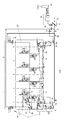
- Fig. 1 and 2 the first embodiment of a device for heat treatment of textile webs is shown, wherein the webs, for example, so-called wet fixations, Fig. 1 and dry fixations, Fig. 2 of textile carriers can act.
- the webs for example, so-called wet fixations, Fig. 1 and dry fixations, Fig. 2 of textile carriers can act.
- other, non-textile, web-shaped webs come into consideration.
- the device consists of a plurality of successive treatment fields 1 to 5, which are each divided into half-fields 1a, 1b, 2a, 2b, 3a, 3b, 4a, 4b, 5a and 5b, wherein of course more or fewer treatment fields are provided within the scope of the invention can.
- Fig. 3 one of the half fields is shown enlarged.
- a textile web 6 is transported by only schematically indicated with arrows transport means 7 in the expanded state through the treatment fields.
- In the treatment fields are impact jet ventilation zones with lower and upper nozzle systems 8, 9 (see Fig. 4 ), which extend over the entire width of the web 6, so that the web is acted upon both from above and from below with a treatment gas 10.
- the half-fields 1a, 1b, 2a, 2b and 3a are assigned to a first treatment section I and the half-fields 3b, 4a, 4b, 5a and 5b to a second treatment section II.
- the first treatment section I has a first central heating system 11 for heating supply air for the first treatment section 1, the heated supply air being supplied to the half fields 1b to 3a via a first supply air supply device 12 connected to the first central heating system 11.
- a second central heating system 13 is provided for heating the supply air for the second treatment section II, which is provided to a second supply air supply device 14 for supplying the supply air to the half fields 3b, 4a, 4b and 5a.
- the half-field 1a at the beginning of the device represents the so-called inlet field, which in contrast to the other ventilation fields, in particular as a ventilation zone can be formed.
- the concentrated exhaust air from the following in the transport direction half fields can be used.
- the last half-field 5b in the second treatment section II represents the outlet field.
- the treatment gas 10 is composed of a certain ratio of supply air 15 and circulating circulating air 16, wherein the supply air 15 in the first and second central heating system 11, 13 heated and the first or second supply air supply means 12, 14 the individual treatment fields or Half fields are fed. Via a temperature-controlled controller 17, an actuator 18 having a mixing device is driven to keep the temperature of the treatment gas 10 by admixing hot supply air 15 at a predetermined level of, for example, 200 ° C. Depending on the type of treatment, different temperatures can also be set in the individual treatment fields.
- the treatment gas 10 is applied to the web 6 via one or more fans 19 via the lower and upper nozzle systems 8 and 9. In order to keep the amount of treatment gas 10 constant, the amount of supply air 15 supplied to the half-field is compensated by a corresponding amount of exhaust air 20 to be discharged.
- the exhaust air 20 is discharged in the two treatment sections I and II via a first exhaust air discharge device 21 and a second exhaust air discharge device 22.
- the second exhaust air discharge device 22 for discharging the exhaust air 20 from the treatment fields of the second treatment section II to the first central heating system 11 for using the exhaust air 20 as supply air 15 in the first treatment section I is connected.
- the entire second exhaust air removal device 22 is highlighted in bold for ease of understanding.
- the first exhaust air removal device 21 is preferably connected to an indirect exhaust air heat exchanger 23 in order to use the residual heat.
- the exhaust air is then fed to a pollutant and / or dust filter before it passes through an exhaust chimney 25 into the atmosphere.
- the two central heating systems 11, 13 each have a burner 11a or 13a, which is preferably designed as a diffusion burner. Alternatively, a fan burner with separate air duct is possible.
- the exhaust gas supplied via the second exhaust air discharge device 22 to the first central heating system 11 is used in the burner 11a as combustion air. Since in the first treatment section I usually more supply air 15 is required than can be provided by the extracted in the second treatment section II exhaust air, it is necessary that the first central heating system 11 additional fresh air 26a is supplied via a first Frischluftzu111technisch, which expediently in an indirect Heat exchanger 27 is heated with the exhaust air of the first treatment section I before it is mixed after the burner 11 a with the supplied and temporarily heated exhaust gas and supplied as supply air to the first supply air supply means 12.
- the supply air supply device 12 is connected via supply means 28 with the second heating system 13 and supplies this with the corresponding combustion air.
- Fig. 1 illustrated operation of the device is mainly intended for the application, in which dried in the first treatment section I and fixed in the second treatment section II.
- the exhaust air of the first treatment section is loaded with a high humidity and therefore rather unsuitable as combustion gas in one of the two central heating systems.
- the exhaust gas of the second treatment section II contains only a small proportion of moisture and can therefore be used in the first treatment section I for concentration during drying with moisture.
- volatile constituents such as organic hydrocarbons, in particular methanol and formaldehyde, volatilize in the second treatment section and are removed with the exhaust gas.
- this exhaust gas is used in the first central heating system as combustion air, the pollutants contained in the exhaust gas are at least partially burned and thus eliminated in a simple manner.
- Fig.2 to ensure actuator or control members 30, 31, 32 and 33 are provided.
- the control and regulating members 31 and 32 are closed to the exhaust air of the first treatment section I via the first exhaust air discharge device 22 to the heat exchanger 23 and to guide the exhaust air of the second treatment section II to the first central heating system 11.
- the actuators 30 and 33 are closed, so that the exhaust air of the first treatment section I is supplied to the second central heating system 13 and the exhaust air of the second treatment section II to the heat exchanger 23.
- Fig. 3 shows a second embodiment of an apparatus for heat treatment of web-shaped webs 6. It differs from the first embodiment, especially in that only one treatment section I 'is provided, which includes all treatment sections 1 to 5. Another difference is that only a central heating system 11 'is provided for heating the supply air for all treatment fields 1 to 5 and only one exhaust air discharge device 21' for discharging exhaust air from the treatment fields.
- the second embodiment agrees with the first embodiment according to the Fig. 1 and 2 are largely the same, so that the same reference numerals have been used.
- the half-fields are also consistent in accordance with Fig. 4 built up.
- the required control range can be significantly reduced and thus a significantly better burnout behavior compared to individual burners provided in each treatment field can be achieved.
- Compared to conventional systems takes place in this system when entering the web in the device targeted flow through the goods with hot exhaust air, which warms up the web and the water contained in it faster and additionally humidifies the exhaust air through water absorption from the goods.
- the exhaust air is brought to a lower temperature level, which also means a more effective use of energy in the process.
- the two central heating systems, which are permanently in operation, the supply air can also be kept at a constant temperature.
- the exhaust air from one of the two treatment sections as combustion air in the central heating system of the other treatment section can also be reduced out of the system exhaust air amount by about half.
- the pollutant and / or dust filter 24 can be dimensioned correspondingly smaller.
Landscapes
- Engineering & Computer Science (AREA)
- Mechanical Engineering (AREA)
- General Engineering & Computer Science (AREA)
- Life Sciences & Earth Sciences (AREA)
- Sustainable Development (AREA)
- Textile Engineering (AREA)
- Treatment Of Fiber Materials (AREA)
- Heat Treatment Of Strip Materials And Filament Materials (AREA)
Applications Claiming Priority (1)
| Application Number | Priority Date | Filing Date | Title |
|---|---|---|---|
| DE102012102096A DE102012102096A1 (de) | 2012-03-13 | 2012-03-13 | Vorrichtung und Verfahren zur Wärmebehandlung von bahnförmigen Warenbahnen |
Publications (2)
| Publication Number | Publication Date |
|---|---|
| EP2639535A2 true EP2639535A2 (fr) | 2013-09-18 |
| EP2639535A3 EP2639535A3 (fr) | 2015-09-09 |
Family
ID=47722175
Family Applications (1)
| Application Number | Title | Priority Date | Filing Date |
|---|---|---|---|
| EP13155999.9A Withdrawn EP2639535A3 (fr) | 2012-03-13 | 2013-02-20 | Dispositif et procédé de traitement thermique de bandes de produits en forme de bandes |
Country Status (2)
| Country | Link |
|---|---|
| EP (1) | EP2639535A3 (fr) |
| DE (1) | DE102012102096A1 (fr) |
Citations (5)
| Publication number | Priority date | Publication date | Assignee | Title |
|---|---|---|---|---|
| DE2616347A1 (de) | 1976-04-14 | 1977-10-27 | Vits Maschinenbau Gmbh | Verfahren und vorrichtung zum aufheizen eines trockners und zum thermischen nachverbrennen der abluft des trockners |
| EP1830146A2 (fr) | 2006-03-13 | 2007-09-05 | Brückner Trockentechnik GmbH & Co. KG | Dispositif destiné à guider des bandes de matériau textile |
| DE10010842B4 (de) | 2000-03-06 | 2009-10-01 | Brückner Trockentechnik GmbH & Co. KG | Vorrichtung zur Behandlung von Warenbahnen |
| EP2345740A1 (fr) | 2006-06-06 | 2011-07-20 | Gen-Probe Incorporated | Oligonucléotides marqués et leur utilisation dans des procédés d'amplification d'acide nucléique |
| EP2354740A2 (fr) | 2010-02-02 | 2011-08-10 | Brückner Trockentechnik GmbH & Co. KG | Dispositif et procédé de traitement thermique de bandes de produits en forme de bandes |
Family Cites Families (5)
| Publication number | Priority date | Publication date | Assignee | Title |
|---|---|---|---|---|
| DE2812966C2 (de) * | 1978-03-23 | 1986-06-19 | Brückner-Apparatebau GmbH, 6120 Erbach | Verfahren zur thermischen Behandlung einer Warenbahn |
| US4133636A (en) * | 1977-06-30 | 1979-01-09 | Blu-Surf, Inc. | Tentor |
| DE3644323A1 (de) * | 1986-12-23 | 1988-07-07 | Brueckner Trockentechnik Gmbh | Verfahren und einrichtung zur thermischen behandlung einer kontinuierlich bewegten textilen warenbahn |
| DE3819258A1 (de) | 1988-06-06 | 1989-12-07 | Michael Dr Spaeth | Brandschutztechnischer filter |
| DE68926701T2 (de) | 1988-08-09 | 1997-02-20 | Matsushita Electric Ind Co Ltd | Datenverarbeitungsgerät zur parallelen Dekodierung und parallelen Ausführung von Befehlen mit variabler Wortlänge |
-
2012
- 2012-03-13 DE DE102012102096A patent/DE102012102096A1/de not_active Withdrawn
-
2013
- 2013-02-20 EP EP13155999.9A patent/EP2639535A3/fr not_active Withdrawn
Patent Citations (5)
| Publication number | Priority date | Publication date | Assignee | Title |
|---|---|---|---|---|
| DE2616347A1 (de) | 1976-04-14 | 1977-10-27 | Vits Maschinenbau Gmbh | Verfahren und vorrichtung zum aufheizen eines trockners und zum thermischen nachverbrennen der abluft des trockners |
| DE10010842B4 (de) | 2000-03-06 | 2009-10-01 | Brückner Trockentechnik GmbH & Co. KG | Vorrichtung zur Behandlung von Warenbahnen |
| EP1830146A2 (fr) | 2006-03-13 | 2007-09-05 | Brückner Trockentechnik GmbH & Co. KG | Dispositif destiné à guider des bandes de matériau textile |
| EP2345740A1 (fr) | 2006-06-06 | 2011-07-20 | Gen-Probe Incorporated | Oligonucléotides marqués et leur utilisation dans des procédés d'amplification d'acide nucléique |
| EP2354740A2 (fr) | 2010-02-02 | 2011-08-10 | Brückner Trockentechnik GmbH & Co. KG | Dispositif et procédé de traitement thermique de bandes de produits en forme de bandes |
Also Published As
| Publication number | Publication date |
|---|---|
| DE102012102096A1 (de) | 2013-09-19 |
| EP2639535A3 (fr) | 2015-09-09 |
Similar Documents
| Publication | Publication Date | Title |
|---|---|---|
| EP2516949B1 (fr) | Procédé et dispositif de séchage de plaques de plâtre | |
| DE2819814C3 (de) | Verfahren und Einrichtung zur Entfernung von Lösungsmitteln aus den insbesondere von einer mit Tiefdruckzylindern arbeitenden Druck- oder Verpackungspresse in einen Maschinenraum abgegebenen Abgasen | |
| EP3332201B1 (fr) | Installation pour le traitement de pièces et opération d'une installation | |
| EP3249326B1 (fr) | Dispositif de séchoir pour une bande textile comprenant un dispositif amélioré destiné à apporter de la chaleur | |
| EP3356753B1 (fr) | Dipositif pour le conditionnement thermique d' objets, particulièrement pour secher des carrosseries de véhicule recouvertes | |
| DE2254848B2 (de) | Anordnung zur thermischen nachverbrennung | |
| DE102009014020A1 (de) | Verfahren und Vorrichtung zum Trocknen von Gütern | |
| DE2616347C3 (de) | Durchlauftrockner für Warenbahnen | |
| EP0264637A2 (fr) | Sécheur de bandes continues, notamment du type offset | |
| DE3390176C2 (de) | Kombination eines Ofens und eines Rauchveraschers und Verfahren f}r deren Betrieb | |
| DE102015209370B3 (de) | Trockner | |
| DE10246394B4 (de) | Fixiereinrichtung und Fixierverfahren für eine Druckmaschine | |
| DE2528334A1 (de) | Verfahren und ofenanlage fuer die waermebehandlung von werkstuecken | |
| DE102015003856A1 (de) | Vorrichtung zur Temperierung von Gegenständen | |
| EP2354740B1 (fr) | Dispositif et procédé de traitement thermique de bandes de produits en forme de bandes | |
| DE3644323A1 (de) | Verfahren und einrichtung zur thermischen behandlung einer kontinuierlich bewegten textilen warenbahn | |
| DE102007051962A1 (de) | Materialbahntrockneranordnung | |
| EP3230671B2 (fr) | Système de séchage pourvu d'une zone de séchage | |
| EP2639535A2 (fr) | Dispositif et procédé de traitement thermique de bandes de produits en forme de bandes | |
| EP1262726A1 (fr) | Dispositif de traitement de bandes continues textiles | |
| EP4399464A1 (fr) | Séchoir pour sécher des plaques à basses températures | |
| EP0971191A2 (fr) | Procédé et dispositif pour traiter des objets par un gaz chauffé | |
| EP4567362A1 (fr) | Technique de réduction de polluants dans des installations de séchage de bords de rive osb | |
| DE20116279U1 (de) | Vorrichtung zur Behandlung von textilen Warenbahnen | |
| DE102024203234A1 (de) | Verfahren zum Trocknen einer bedruckten Papierbahn, Trockenstrecke |
Legal Events
| Date | Code | Title | Description |
|---|---|---|---|
| PUAI | Public reference made under article 153(3) epc to a published international application that has entered the european phase |
Free format text: ORIGINAL CODE: 0009012 |
|
| AK | Designated contracting states |
Kind code of ref document: A2 Designated state(s): AL AT BE BG CH CY CZ DE DK EE ES FI FR GB GR HR HU IE IS IT LI LT LU LV MC MK MT NL NO PL PT RO RS SE SI SK SM TR |
|
| AX | Request for extension of the european patent |
Extension state: BA ME |
|
| PUAL | Search report despatched |
Free format text: ORIGINAL CODE: 0009013 |
|
| AK | Designated contracting states |
Kind code of ref document: A3 Designated state(s): AL AT BE BG CH CY CZ DE DK EE ES FI FR GB GR HR HU IE IS IT LI LT LU LV MC MK MT NL NO PL PT RO RS SE SI SK SM TR |
|
| AX | Request for extension of the european patent |
Extension state: BA ME |
|
| RIC1 | Information provided on ipc code assigned before grant |
Ipc: F26B 21/04 20060101ALI20150731BHEP Ipc: F26B 13/10 20060101AFI20150731BHEP Ipc: F26B 23/00 20060101ALI20150731BHEP |
|
| STAA | Information on the status of an ep patent application or granted ep patent |
Free format text: STATUS: THE APPLICATION IS DEEMED TO BE WITHDRAWN |
|
| 18D | Application deemed to be withdrawn |
Effective date: 20160310 |