EP2639596A1 - Flugobjekt, das über elektromagnetische Strahlenbündel gelenkt wird - Google Patents
Flugobjekt, das über elektromagnetische Strahlenbündel gelenkt wird Download PDFInfo
- Publication number
- EP2639596A1 EP2639596A1 EP13159068.9A EP13159068A EP2639596A1 EP 2639596 A1 EP2639596 A1 EP 2639596A1 EP 13159068 A EP13159068 A EP 13159068A EP 2639596 A1 EP2639596 A1 EP 2639596A1
- Authority
- EP
- European Patent Office
- Prior art keywords
- flying object
- antennas
- antenna
- beams
- receiving
- Prior art date
- Legal status (The legal status is an assumption and is not a legal conclusion. Google has not performed a legal analysis and makes no representation as to the accuracy of the status listed.)
- Granted
Links
Images


Classifications
-
- G—PHYSICS
- G01—MEASURING; TESTING
- G01S—RADIO DIRECTION-FINDING; RADIO NAVIGATION; DETERMINING DISTANCE OR VELOCITY BY USE OF RADIO WAVES; LOCATING OR PRESENCE-DETECTING BY USE OF THE REFLECTION OR RERADIATION OF RADIO WAVES; ANALOGOUS ARRANGEMENTS USING OTHER WAVES
- G01S1/00—Beacons or beacon systems transmitting signals having a characteristic or characteristics capable of being detected by non-directional receivers and defining directions, positions, or position lines fixed relatively to the beacon transmitters; Receivers co-operating therewith
- G01S1/02—Beacons or beacon systems transmitting signals having a characteristic or characteristics capable of being detected by non-directional receivers and defining directions, positions, or position lines fixed relatively to the beacon transmitters; Receivers co-operating therewith using radio waves
- G01S1/08—Systems for determining direction or position line
- G01S1/42—Conical-scan beacons transmitting signals which indicate at a mobile receiver any displacement of the receiver from the conical-scan axis, e.g. for "beam-riding" missile control
-
- F—MECHANICAL ENGINEERING; LIGHTING; HEATING; WEAPONS; BLASTING
- F41—WEAPONS
- F41G—WEAPON SIGHTS; AIMING
- F41G7/00—Direction control systems for self-propelled missiles
- F41G7/20—Direction control systems for self-propelled missiles based on continuous observation of target position
- F41G7/24—Beam riding guidance systems
- F41G7/28—Radio guidance systems
-
- G—PHYSICS
- G01—MEASURING; TESTING
- G01S—RADIO DIRECTION-FINDING; RADIO NAVIGATION; DETERMINING DISTANCE OR VELOCITY BY USE OF RADIO WAVES; LOCATING OR PRESENCE-DETECTING BY USE OF THE REFLECTION OR RERADIATION OF RADIO WAVES; ANALOGOUS ARRANGEMENTS USING OTHER WAVES
- G01S1/00—Beacons or beacon systems transmitting signals having a characteristic or characteristics capable of being detected by non-directional receivers and defining directions, positions, or position lines fixed relatively to the beacon transmitters; Receivers co-operating therewith
- G01S1/02—Beacons or beacon systems transmitting signals having a characteristic or characteristics capable of being detected by non-directional receivers and defining directions, positions, or position lines fixed relatively to the beacon transmitters; Receivers co-operating therewith using radio waves
- G01S1/08—Systems for determining direction or position line
- G01S1/14—Systems for determining direction or position line using amplitude comparison of signals transmitted simultaneously from antennas or antenna systems having differently oriented overlapping directivity-characteristics
Definitions
- the present invention relates to the field of flying objects towards an objective.
- the present invention more particularly relates to an object flying towards an objective guided on electromagnetic beams.
- These autonomous guidance systems generally implement inertial means embedded, associated with a set of electromagnetic designation, laser or infrared, pointed in the direction of the objective.
- the volume of the on-board electronics is significant and directly impacts the cost of the machine. It is possible to download in the flying object the position of the target according to the satellite positioning system (or GNSS for Global Navigation Satellite System) such as the GPS, Galileo or Glonass system and to request a rallying of the object. towards this position. This presupposes an embedded GNSS system and a fixed rally point.
- satellite positioning system or GNSS for Global Navigation Satellite System
- the elevation is very delicate, because of the reflections.
- the location may also be disturbed in the horizontal plane and / or by lateral reflections on surrounding objects, such as human constructions for example.
- the onboard transmitter does not measure the distance traveled, unless it has an "answering" function. In the latter case, the cost and the volume of the electronics increase significantly.
- An object of the invention is in particular to correct the aforementioned drawbacks and in particular to minimize for objects flying towards an objective mass, volume, power consumed and / or the cost of embedded electronics.
- the subject of the invention is an object flying in the direction of an objective guided on electromagnetic beams as described in the claims.
- horizontal and vertical planes respectively designate substantially parallel planes and substantially perpendicular to the ground, the latter being taken as a reference.
- the direction of movement of the flying object will be chosen to define the front and the back of the objects.
- an antenna is "low” when the latter is located in the half plane between the ground and a horizontal axis passing through the axis of revolution of the fuselage of the flying object.
- the Figures 1a and 1b represent exemplary embodiments of guiding at least one flying object 2 towards an objective 3.
- a device for guiding electromagnetic beams 21, 22 of at least one flying object 2 in the direction of an objective 3 comprises, among other things, a pointing means, an assembly comprising at least three transmitting antennas 46 and at least one transmitter operating for example according to a millimeter wavelength.
- Each transmitter may comprise a waveform generator delivering a signal to each of the transmit antennas so as to form the guide beams.
- a millimeter wavelength wave makes it possible to obtain thinner, more directional beams and thus to increase the accuracy of the guidance.
- an increase in the frequency causes an increase in the gain of the antenna. It is also known that the losses, for example by atmospheric absorption, are very high in this frequency band.
- these losses will allow greater discretion of the device and thus reduce the possibility of detecting the guide device according to the invention.
- the fineness of the beams as well as that of the side lobes also makes it possible to increase the discretion of the device.
- the transmitter or emitters according to the invention are not limited to this frequency band and can also operate at other wavelengths.
- the transmission frequency is around a frequency substantially equal to 80 gigahertz.
- the guiding device comprises three identical and independent emitters. These transmitters can be separate or constitute a single physical set.
- the transmitter or emitters may be miniature emitters.
- the transmitter or emitters will be of low power to limit the power consumption and thus increase the autonomy of the flying object 2.
- Each transmitter can power one or more antennas for example sequentially.
- the transmitter or emitters generate the beams in one or more rectilinear polarizations.
- the pointing means may for example be a radar, an optronic ball, a day and / or thermal camera such as an infrared camera or any other optical or optoelectronic pointing system equivalent.
- This means has the function of designating, the point of arrival or the objective to be reached by the flying object and to "hang it".
- This objective 3 or target can be fixed or mobile.
- the electromagnetic beams 21, 22 are harmonized at an angle to the direction of designation of the pointing means. The direction of these beams is thus enslaved with the pointing means so that they point towards the objective 3 and that they are oriented along a straight line passing through the pointing means and the objective to be achieved by the 2.
- this line will be named designation axis 35.
- the harmonization or servocontrol of the radio electric axis that is to say the axis of the electromagnetic beams 21, 22, relative to the the target axis of the optical pointing means, or designation axis 35, is made statically on the platform on which is mounted the pointing means.
- the correction values that is to say the bias in azimuth or elevation, may for example be compensated by peelable shims.
- they can be taken into account by the guide device for the formation and orientation of the beams at the departure of the flying object 2.
- these correction values can be transmitted. to the receiver of the flying object 2 to be guided as correction parameters before the departure of the latter.
- the transmitting antenna or antennas of the guiding device 1 are distributed on the pointing means and are oriented along an identical axis so as to be able to emit the different electromagnetic beams centrally about a designation axis 35 directed towards the target. .
- Each beam is emitted in different planes so as to locate the flying object in the space.
- each beam is encoded differently.
- the angles of inclination of these antennas are such that the beams emitted, taken in pairs, intersect for example at 3dB at the half of the emission lobe.
- the figure 2 illustrates the overlap of the lobes of the emission beams at 50% according to an embodiment of an amplitude monopulse-type guidance.
- a section of the guide emission beams in a single plane is shown so as not to burden the figure.
- the same representation exists according to the other orthogonal planes.
- an encoding system consists in transmitting each beam with a different frequency.
- the antennas emit at different frequencies so that the receiver can differentiate the different lobes in frequency.
- Another coding system may consist in transmitting each beam with the same frequency but with different phase codes.
- the beams are emitted with the same frequency but according to different orthogonal codes.
- the beams are coded according to a combination of frequencies and different orthogonal codes.
- the different electromagnetic beams are pointed in the same direction of view and oriented so that the gains of their respective antennas are identical for two orthogonal rectilinear polarizations.
- a first guidance strategy may be to illuminate the objective to be achieved by using beams of different apertures.
- the figure 1a illustrates an example of such an embodiment in a monopulse amplitude configuration.
- the phase monopulse configuration is used.
- the amplitudes emitted are identical and the elementary sources or the antennas are arranged in such a way that they give signals of identical amplitudes whatever the direction considered of the target 3 or the designated point .
- the measurement of the phase of the signal received by the receiving antennas of the flying object 2 thus makes it possible to obtain the angle of the trajectory of the flying object 2 with respect to the designation axis 35 of the guiding device 1 .
- FIG. 3b illustrates through an exemplary embodiment, such a guide mode.
- the emitter or emitters of the guiding device 1 In order to guide the assembly comprising at least one flying object 2, the emitter or emitters of the guiding device 1 generate signals at the antenna or antennas 46 in order to emit a set of beams comprising at least three electromagnetic beams of separate guidance.
- the guiding device 1 emits coarse beams 21 and thin beams 22 all pointing in the same direction.
- the proposed solution is to have a wide beam 21 to pre-guide the flying object 2 towards the center of said wide beam and a thin beam to obtain the final precision for guidance to the objective 3.
- the wide beams may be alternated with thin beams.
- each beam 21, 22 is emitted with different gains for a given direction and come from the same phase center.
- the coarse beams 21 are used in the initial phase to guide the flying object and position it in the finer beams 22.
- the thin beams 22 are then used by the flying object 2 in its flight phase to move towards the objective 3. These beams 22 are intended to achieve a fine guide.
- the location of the flying object 2 inside the bundles is naturally done by the object itself, by performing a filtering separation adapted to the signals received from each beam of the illuminator 1, then by a weighing of the amplitudes of the coarse bundles 21 and then thin bundles 22.
- the same principle is used with a monopulse phase configuration.
- the coarse 21 and fine beams 22 have the same gain whatever the direction considered and it is the arrival phase that changes depending on the direction considered.
- the phase center at the emission is different for each beam.
- the elementary sources 31 or the transmission antennas 46 of the guide device 1 are arranged in such a way that they provide signals of identical amplitude whatever the direction considered of the target 3 or the designated point.
- the relative phases of the signals measured in each channel are a function of the angle with respect to the direction of the designation axis 35.
- the measurement of the phase thus makes it possible to obtain the angle with respect to the axis 35, the location of the flying object inside the beams can therefore be done by multiple weighings on the phases of the signals of the beams of the beam. guide.
- three coarse beams 21 and three thin beams 22, for example emitted equilaterally, are necessary for a good location of the flying object 2.
- a higher number of beams can be used.
- a power management can be realized during the emission of the beams 21, 22.
- the guide device 1 on electromagnetic beams can comprise amplifiers controlled amplitude.
- the beams 21, 22 may be emitted with a higher or lower power depending on the distance of the objective or the target 3 to reach.
- this allows the device to guidance 1 to increase its discretion and thus reduce its probability of detection.
- the coarse beams 21 are used only during the initial phase of guiding the flying object, they can be emitted with a lower power than that of the thin beams. In fact the coarse beams serve to guide the flying object towards the fine bundles and once these bundles are rallied, it is sensible not to move away from it, in this phase, they are therefore of no use.
- the figure 1b illustrates another electromagnetic beam guidance solution that illuminates the target by emitting ambiguous interferometry slices.
- this figure shows the fringes as viewed in a single plane.
- the same representation of the interference fringes exists in another plane, perpendicular to the latter, emitted by two separate emitters preferably of the same distance.
- the emission can be achieved by gap antennas 30 emitting a network of very fine brushes 22, each at different frequencies.
- the brushes 22 emitted by each antenna having all the same frequency the result of the measurement made by the receiver is totally ambiguous.
- the transmitter knows precisely to position itself inside each end brush 22 without knowing where it is located.
- coarse beams 21 are emitted.
- the receiver can thus position itself among the different brushes by weighing on the amplitudes and / or on the phases of the signals of the coarse beams 22, depending on whether the technique used at transmission is discriminant in phase, amplitude or combination of both.
- the transmission network comprises at least three coherent transmitters separated by more than half a wavelength each and emitting at different frequencies. This allows for fringes of ambiguity.
- a guiding solution can also be obtained with ambiguous emission lobes for fine brushes or by phase shifters known to those skilled in the art under the name of "true time delay” for "tilting" the lobe of the desired value .
- the guiding device comprises four antennas 56 and emits four beams with code in rectilinear polarization.
- the transmission part of the device 1 comprises a driver 41 and a frequency-controlled oscillator and phase 42 or digital direct frequency synthesizer (DDS for Direct Digital Synthesis according to the Anglo-Saxon term).
- the signals from these two devices 41, 42 are then mixed using mixers 43.
- the output signals of each mixer 43 are then amplified by an amplifier 44 and filtered using a bandpass filter 45.
- the signals are sent to antennas 46 to be transmitted.
- antennas 46 operate in horizontal polarization and two in vertical polarization.
- a slant polarization system such as for example angles of + 45 ° and -45 ° is possible.
- the transmission frequencies can be distinct or identical.
- the signals are emitted with different phase codes in order to differentiate the beams.
- the Figures 5a and 5b respectively represent a side view and back of an exemplary embodiment of a flying object 2 towards an objective according to the invention.
- the flying object 2 has a fuselage 52 of substantially cylindrical shape with at one end a head or front tip 51 of substantially conical shape.
- This flying object 2 comprises a thruster 53 placed at the rear of the object 2, that is to say at the opposite end of the nose 51 and four guide fins 54 or guide ducks.
- Each guide fin 54 passes through an axis substantially perpendicular to the axis of revolution of the fuselage 52.
- the flying object 2 comprises at least one guide fin 54.
- the orientation of the guide fin or fins 54 is controlled by a control module comprising calculating means and adapted to establish control commands, in the direction of the or the guide vanes, for modifying the trajectory of the flying object 2 so as to guide the latter.
- the flying object 2 also comprises, on the front of its fuselage 52, four receiving antennas 56 distributed uniformly around the fuselage 52 and oriented substantially perpendicular to the axis of revolution of the fuselage. These reception antennas 56 are oriented so as to be able to receive a signal coming from the rear of the flying object 2.
- the reception antennas 56 are placed at the rear of the guide vanes 54.
- the four antennas 56 are each connected to a receiver 62.
- a receiver 62 is connected to several antennas 56, the received signals being for example processed after multiplexing.
- the or the guide fins 54 are retractable. Before firing the flying object 2, the fins 54 are retracted into recesses provided in the body of the fuselage 52. After the firing, these fins 54 are deployed out of their housing so as to guide the flying object 2 in its flight phase.
- the flying object 2 has two pairs of receiving antennas 56 arranged around its fuselage perpendicularly two by two and each perpendicularly to the axis of revolution of the fuselage. These antennas 56 are oriented rearward so as to receive the signals from the guide device 1 and preferably disposed at the rear of the guide vanes.
- the receiving antennas are polarized in a rectilinear polarization, a pair of diametrically opposed antennas in a horizontal polarization and a second pair in a vertical polarization.
- the odd antennas 1 and 3 will be polarized in a vertical polarization and the next pair antennas 2 and 4 a horizontal polarization.
- the numbers of the transmitting antennas of the guide device according to the invention follow the same rule.
- F1 to F4 will be noted the respective frequencies of the signals emitted by the transmit antennas 1 to 4.
- the flying object 2 has two receiving antennas 56 arranged around its fuselage 52 along an axis perpendicular to the axis of revolution of the fuselage 52, the two antennas 56 being diametrically opposed.
- the receiving module of the flying object 2 comprises at least one onboard receiver and at least one antenna.
- the configuration with a single antenna is possible because the flying object is rotated on itself during its movement.
- the switching speed must be adapted to the speed of rotation of the machine to be guided.
- the reception module allows a decoding of the signals emitted by the guiding device thus allowing a natural location of the flying object in the different emitted beams.
- the receiving antennas 56 of the flying object 2 are arranged in such a way that the signal received by at least one of them is not altered by reflections on the ground or on a lateral obstacle on a plane. side of the trajectory of the flying object regardless of the position of the flying object. It should be noted that the flying object 2 being in rotation on itself, the signals are periodically received by the different antennas 56 according to the same geometry, which makes it possible to perform a calibration of the gains of the reception chains associated with each of these antennas.
- the flying object 2 establishes its own angular location in a site and in a direction-finding field on the signals received by its antenna or antennas 56, from the beams of signals emitted by each of the emission sources. of the guiding device 1.
- the flying object 2 comprises at least one wave receiver 62 operating, for example, at a millimeter wavelength, its control, a reception control circuit 65 and a calibration circuit. , a splitter 61 and preferably four antennas in rectilinear polarization (for example two in horizontal polarization and two in vertical polarization) according to the synoptic of principle of the figure 6 .
- a configuration with at least one receiving antenna 56 is possible.
- the receiver or receivers 62 operate in a millimeter wave in a frequency band corresponding to the transmission device.
- the transmission frequency is of the order of 80 GHz.
- the receiver knows its position and location and bearing relative to the linear path connecting the designation or pointing means to the target 3 or the designated point.
- the flying object is thus driven, directed by the beams and at the same time, the flying object reads the information of the beams to locate and go towards the center of the beams to go towards the objective pointed by the designator.
- An advantage of this embodiment is that several flying objects 2 can be guided at the same time on the same beams. Indeed, according to the invention there is no real direct communication between the transmitter and the receiver of the flying object 2.
- the beams act as a kind of corridor or funnel in which the flying objects 2 self-orient towards the center by reading the information of the beams.
- the workload for the transmitter is the same regardless of the number of flying objects 2 to be guided.
- the guide load is ensured by the receivers embedded in the objects to be guided 2.
- reception control circuit 65 is to direct the four-way switch to one or four to four channels so that different receive channels can receive the same signal.
- this can be used, for example, to calibrate the gain of each channel.
- the selection circuit may be an input and four output switching circuit known to those skilled in the art under the name SP4T or Single-Pole Four-Throw (switch) according to the Anglo-Saxon term.
- SP4T Single-Pole Four-Throw
- a skew of the channels can be detected.
- a gain adjustment on a channel can be made to take into account differences in the gain of the chain and compensate for this asymmetry.
- compensation for the gain error can be made numerically. Indeed, given the application, an analog compensation of the chain is not necessary. Of course, this compensation must be done in all the frequencies used by the pairs transceivers.
- This verification of the symmetry of two diametrically opposed channels can also be done by selecting the same channel by making a simultaneous measurement of the signals received by an antenna using two different receivers.
- calibration solutions are also possible, for example the implantation of a fifth receiver serving as a reference.
- this transmitter can analyze their relative variations with respect to the signals measured on the fifth reference channel.
- This function can be allocated to a randomly pseudo channel that will be paralleled with another channel to calibrate it.
- the decoding When using a code, the decoding will participate in the elaboration of the precision.
- the codings will make it possible to remove the ambiguities related to the use of identical frequencies which will be differentiated by the decoding
- the flying object 2 is guided by the various beams 21, 22 but also uses these beams to locate in space.
- the calculation means of the steering module of the flying object 2 can calculate its location and guidance parameters from information conveyed by the beams 21, 22 guide.
- the calculation means of the control module can for example calculate the angular location parameters in elevation and azimuth of the flying object 2 by two-plane deviation from the signals received by the receiving antennas 56.
- the means of calculation will reject signals disturbed by at least one reflection before establishing the guidance and location parameters.
- the flying object 2 is able to know where it is in space using the beam information, some of the gyroscopes can be removed simplifying and thus lightening the inertial unit of the flying object 2.
- the Weight gain can for example be used to increase the autonomy of the flying object 2 and / or increase the weight of the "payload”.
- each receiver comprises a frequency-controlled coherent reference oscillator, low-noise amplification circuits, filter circuits, a mixer and sampling, coding and signal processing means based in particular on a spectral analysis for example by fast Fourier (or FFT) or analog (or AFT according to the abbreviation Anglo-Saxon).
- FFT fast Fourier
- AFT analog
- the figure 7 presents an exemplary embodiment of a receiver for reading the position in the beams according to the invention.
- the receiver analyzes the amplitude values of the received signals.
- the phase of these signals is taken into account for the calculations. The phase measurement is a little more complicated to integrate although it allows to obtain more precise results.
- the receiver uses an autotransposition method to evaluate its position.
- the signals received by the diametrically opposed antennas for example the antennas 1 and 3 or 2 and 4 in a configuration with 4 receiving antennas, therefore of the same polarization, are mixed together.
- a signal is taken as reference and is mixed with the other signal so as to obtain the difference between these two frequencies.
- the position of the object is thus identified by the decoding of the frequency differences between the signals received by the diametrically opposite antennas without having to know the exact frequencies of each of the received signals.
- the frequency difference between the signals transmitted at the frequencies F1 and F3 and the frequency difference between the signals transmitted at the frequencies F2 and F4 are deliberately chosen different.
- the frequency deviations will be chosen so that they are significant in relation to the possibilities of the filtering means 71 of the receivers and the performance of the mixers 70.
- the frequencies will be chosen so that they are not too far apart and that their difference makes it possible to use a filter 71 and an analog-to-digital converter (ADC) 72 to low cost.
- ADC analog-to-digital converter
- the highest amplitude signal will be injected into the input IF (Intermediate Frequency) of the mixer 70 and the lines of the mixing products will be analyzed by a frequency analysis 73.
- This analysis may be performed, for example by Fast Fourier Transform (FFT for Fast Fourier Transform), by Analogic Fourrier Transform (AFT) or any other method of transition from the time domain to the domain. frequency. Measuring relative amplitudes and / or relative phases between the signals allows the moving object to locate in the received beams. The trajectory of these beams being slaved to the optical sight, the guidance is naturally performed.
- FFT Fast Fourier Transform
- AFT Analogic Fourrier Transform
- this embodiment uses no local oscillator such as a quartz or a frequency generator.
- This solution also eliminates the problem of not starting the local oscillator when leaving the flying object.
- the stability and complexity problems of the free oscillators are found in the guiding platform and not within the flying object, which reduces the integration constraints in the latter.
- the analyzed signals have relatively low frequencies, typically frequencies of the order of ten or a hundred megahertz, so that a low-end digital analog converter 72 can suffice for calculations which simplifies the circuit of the receivers and reduce the cost.
- the figure 8 presents an alternative embodiment in which the self delay transposition is used.
- the two signals of the same polarization for example, the two signals transmitted in horizontal polarization at the frequency F2 and F4 are received by the same antenna 56.
- a filter 81 for example, passes high, separates the signal at the low frequency and delays it. This signal, at the low frequency, is then mixed with the other signal received in a mixer 70.
- a mixed signal is obtained at the frequency F4-F2 which will then be processed as in the embodiment previous.
- the low frequency is used to demodulate the high frequency but different combinations are also possible.
- this solution allows a redundancy of the signals.
- the rotation of the flying object Due to the rotation of the flying object, the use of a single antenna and a single reception channel is possible. This allows, by using the rotation of the object, a positioning in the two axes.
- the cooling time of the information depends, in this case, on the speed of rotation.
- the measurement of the rotation of the flying object is obtained by measuring the amplitude of the signals received and by determining the maximum of these signals.
- the receiving device may comprise more than two receivers, in particular for detecting and rejecting the signals disturbed by the reflections, for example on the ground, the relief or on the walls or any other obstacle.
- the self-transposition function can also be replaced by a frequency-controlled oscillator associated with at least one filtering adapted to the expected frequency or code, which itself may be common to the receivers.
- a frequency-controlled oscillator associated with at least one filtering adapted to the expected frequency or code, which itself may be common to the receivers.
- the coding may be a frequency coding and / or a coding in phase. In this case, a code system of orthogonal phases between them can be employed.
- the transmitter of the guide device transmits the guide beams towards the target, however there are losses or leakage of signals, for example due to side lobes.
- the flying object Before separation from its launching platform, the flying object is close to this transmitter, its antennas can therefore capture signal losses for example losses by diffuse lobes, side lobes etc.
- the captured signals can be used for an initialization step. Leakage of signals picked up by the antennas of the flying object can be used to check the correct operation of the receiver of the flying object or to perform self test or "function test" functions. For example, inside the housing of the flying object and before its separation from the launch platform, a first test may consist in verifying that the receiver of the flying object captures the signals emitted by the guidance device.
- These signal leaks can be used by the flying object to "catch" in frequency and phase on the generator of the guide device. Once the guide frequencies have been sensed, the frequency corrector of the receiver of the flying object can tune the frequencies. Thus, after separation of its launch platform, the receiver of the flying object can be hooked in frequency and in phase on the generator of the guiding device.
- or Fb (0)
- These measurements of frequency deviations can be stored in a memory zone of the flying object. According to a particular embodiment, these measurements are stored in a common processing memory zone 74.
- the receiver will measure the difference in frequency between the different beams. Due to the Doppler effect, this difference in frequency is different from that when the object is stationary.
- the stationary beat frequency recorded by the flying object the The receiver of the latter can measure, by a differential calculus, the doppler effect and thus estimate its velocity.
- Information on the parameters relating to the trajectory in space and the presentation of the flying object 2 can be obtained from the guide beams 21, 22.
- control module may know the radial speed of the flying object, for example, to measure the inclination of the guide vanes during the displacement of the flying object 2.
- the control module of the flying object 2 will send a control command so as to incline the or the guide vanes 54 at a greater or lesser angle depending on whether the flying object 2 is moving at high speed or at low speed. Knowing the speed of the flying object can also be used to check that the flight is correct. This may allow a module of the flying object 2 to destroy said object 2 in flight if it realizes, for example, that the speed is inconsistent, that is to say that the measured speed comes out of a range predefined values.
- the calculation of the speed can be obtained by integrating time.
- Dr. ⁇ k + 1 ⁇ Tr 1 2 ⁇ ⁇ r kTr ⁇ Tr 2 + Vr kTr ⁇ Tr + Dr. kTr
- the average speed is estimated by calculating the central value of the frequency spectrum calculated at the output FFT, over a duration Tr.
- the accuracy of the estimation of the speed is substantially equal to 1/10 th of the width of the analysis filter, ie 0.3 m / s and the operating times for the guidance is estimated at about 10 seconds. This gives an uncertainty of about 3 m on the measurement of the radial distance.
- the control module also uses the information of the guide beams 21, 22 to calculate an estimate of the site of the flying object 2.
- the signals received by the various antennas of the on-board transmitter are separated after transposition in the frequency domain, for example after a fast Fourier transform. This separation can be direct if these signals correspond to sinusoids of different frequencies. In the case where the signals have been encoded in phase, in amplitude or in frequency, this separation is carried out for example by a suitable correlator.
- the signals received by at least one receiving antenna of the flying object may have been disturbed by reflections on the ground.
- the figure 9 shows, for a reception coefficient of 0.9 and a wavelength of 4 mm, the shape of the amplitude of the interference fringes as a function of the distance in a case where the object flies at 1 m at above ground, and where the receiver is also 1 m above the ground.
- a first solution for rejecting the signals that have undergone reflection may consist in checking the amplitude coherence of the signal received over time, for example by analyzing the amplitude of the signal received over time. Indeed, the machine moving with a very high speed, for example greater than 100 m / sec, the amplitude of the received signal varies very rapidly as a function of time, in the presence of reflections on the ground, especially in the early moments after the exit of the launch tube.
- a second solution may consist in using in reception at least one adapted polarization antenna.
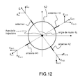
- the determination of the "high” antenna is made by comparing the amplitudes received by the two diametrically opposite antennas.
- the term “high” antenna means the antenna substantially perpendicular to the ground and not facing it. This receiving antenna is taken as a reference because, because of its position, the probability of it being reached by a signal having undergone a reflection is very small. Indeed, the fuselage of the flying object prevents the signals reflected on the ground from reaching this antenna.
- the estimation of the site is then obtained by monopulse measurement on the signals whose amplitude is not disturbed.
- a measurement of the speed of rotation can be made and a complete determination of the position of the machine relative to the vertical is controlled.
- the position is known to k ⁇ near, k represents an integer, and multiple paths are used to remove ambiguity.
- the figure 10 presents the amplitude of the difference of the signals received by two receiving antennas arranged perpendicularly to the ground and diametrically opposed as a function of distance, in the same hypotheses as above, for two transmitting antennas, of the guiding device, spaced by 10 cm in height.
- the control module can calculate an estimate of the azimuth of the flying object 2 for example by a calculation based on monopulse deviation information.
- FIG. 11 An example configuration of the receiving device to overcome both reflections on the ground and lateral reflections by the diversity of position of the antennas is shown figure 11 .
- the antennas are arranged in such a way that the body of the fuselage of the flying object acts as a mask for at least one receiving antenna and prevents it from being disturbed by the multiple paths due to lateral reflections or floor. For this purpose, it will be assumed that two lateral reflections from two different sides can not occur.
- the guide beams 21, 22 are emitted at different frequencies and in two different polarizations, such as horizontal polarization and vertical polarization.
- the measurement of the value of the amplitudes of the signals received at the frequencies F1 and F3 gives the positioning with respect to the vertical beams and the measurement of the value of the amplitudes of the signals received at the frequencies F2 and F4 give the positioning the flying object 2 relative to the horizontal beams.
- the amplitude of these signals is maximum when the receiving antennas of the flying object are in phase with the transmitting antennas.
- the amplitude of the signals received on the antennas 1 and 3 will be maximum when the latter will be vertical and zero when they are horizontal.
- the amplitude of the signals received on the antennas 2 and 4 will be maximum when the latter will be horizontal and zero when they are vertical
- the measurement of the position performed by the antennas can then change, antennas previously used to measure the elevation naturally settling on the azimuth measurement by simple change of frequency.
- a measurement of the amplitudes of the frequencies F1 and F3 is carried out on different receivers. The gaps can then be analyzed. This solution is of course valid for the azimuth.
- the figure 10 represents the difference in amplitude, in dB, between the signals received by two diametrically opposite reception antennas as a function of the distance.
- the received signals should be identical, to attenuation related to the multi trips.
- only "low" antennas in the direction of the ground are susceptible to disturbances.
- the body of the fuselage of the flying object acts as a screen protecting the "high" antennas from the reflections on the ground as illustrated.
- Figures 11a and 11b are examples of the received signals received by two diametrically opposite reception antennas as a function of the distance.
- This principle can be generalized, considering a generation of finer brushes, centered on the axis guiding device / objective and different frequency.
- the receivers can this time synchronize on frequencies Fp1 to Fp4 (Fp1 to Fp4 representing the frequencies of the fine beams).
- Fp1 to Fp4 representing the frequencies of the fine beams.
- the beam being finer, the gain will be higher and the auto transposition will naturally hang on the frequency Fp1 instead of hanging on F1 (respectively Fp3 instead of F3).
- the calculation algorithms are the same as for the measurement in the coarse beam.
- the passage in the precise brush will be detected by the guided object using the codes carried by the various frequencies Fp1 to Fp4.
- the objective remains the rallying of the flying object 2 to guide in the center of the beam.
- Another possibility may be to measure the amplitudes of the interferometry fringes and only the antennas of the flying object receiving identical amplitudes will be considered as undisturbed by the multipath of the reflections. Antennas measuring amplitude variations will instead be considered to be in the presence of multiple paths.
- the transmitting device uses antennas in vertical or horizontal linear polarization.
- the polarization of the wave received by the receiving device comprises for each transmitting antenna a component in vertical polarization, and a component in horizontal polarization, a function of the roll angle.
- the amplitude ratio between the two components may allow the calculation means of the control module to establish an estimate of the roll.
- the same calculation can be performed on the signals from the different antennas of the transmission device, so as to consolidate the measurement.
- the multiple paths can also be used to determine the position of the flying object to guide relative to the ground.
- the angular position of two antennas arranged diametrically opposite on the fuselage differs from 1 mrd to 50 m.
- This angular difference can be detected by a measurement base of sufficient length, typically of the order of 10 cm to 80 GHz.
- the transmitting antennas of the guide device By spacing the transmitting antennas of the guide device by 10 cm, the position of each receiving antenna of a flying object with a diameter of about 10 cm can be measured when the latter is at a short distance.
- the deduction of the instantaneous position of each of the antennas can be calculated by integrating the number of turns by counting the half-rotations of the flying object.
- This solution can also be improved by the measurement by comparing in a differential manner the amplitude variations of the received signals corresponding to the diametrically opposed antennas with respect to the fuselage.
- the indeterminacy can be raised by applying a deflection in a given direction and correlating the measurements with the reaction of the flying object.
- One advantage of this method is that the lifting of indeterminacy is immediate.
- This detection can be done instantaneously if, for example, four reception antennas are uniformly distributed over the fuselage section or sequentially when only two diametrically opposed antennas are distributed over the fuselage section 52. According to a variant embodiment, depending on the the speed of rotation and the speed of the flying object, by making sequential measurements, the detection can also be performed when the flying object has only one receiving antenna.
- the ambiguity on the roll angle can be raised by placing in the fuselage 52 of the flying object 2 an onboard sensor.
- This sensor may for example be of the accelerometer or magnetometer type.
- the signal delivered by this sensor will provide angular position information of low precision, but sufficient to lift the ambiguity "up-down" or "left-right".
- These different algorithms for estimating the radial velocity, the distance traveled, the site, the azimuth and the roll may be for example stored in one or more memory areas of the flying object so as to be executed by the calculation means of the steering module of the flying object.
- the flying object 2 towards a target may be part of a system for launching at least one flying machine 2 towards a target.
- This system may comprise a device for guiding a flying object implementing the guiding method described above and at least one flying object 2 in the direction of an objective as described in the description.
- the system may also include at least one support means 10 of at least one flying object 2 before it is sent.
- the launch system can be embedded on a mobile platform such as an aeronautical or maritime platform or a land vehicle.
- the system can be portable to the back of a man. It may for example be worn by a servant such as an anti-air missile fired at the shoulder (or MANPADS for MAN-Portable Air-Defense Systems according to the English terminology) or ground-ground.
- the flying object 2 may have different types of trajectory.
- the trajectory can be rectilinear, for example in the case of a launching system embarked on an airborne platform.
- the trajectory can be ballistic and then rectilinear.
- the guiding of the flying object (2) by the guiding device 1 may, for example, be performed on the rectilinear part of said trajectory.
Landscapes
- Engineering & Computer Science (AREA)
- Remote Sensing (AREA)
- Computer Networks & Wireless Communication (AREA)
- Physics & Mathematics (AREA)
- General Physics & Mathematics (AREA)
- Radar, Positioning & Navigation (AREA)
- Aviation & Aerospace Engineering (AREA)
- Chemical & Material Sciences (AREA)
- Combustion & Propulsion (AREA)
- General Engineering & Computer Science (AREA)
- Aiming, Guidance, Guns With A Light Source, Armor, Camouflage, And Targets (AREA)
- Radar Systems Or Details Thereof (AREA)
Applications Claiming Priority (1)
| Application Number | Priority Date | Filing Date | Title |
|---|---|---|---|
| FR1200786A FR2988178B1 (fr) | 2012-03-15 | 2012-03-15 | Dispositif de guidage sur faisceaux electromagnetiques, objet volant et systeme de lancement associe |
Publications (2)
| Publication Number | Publication Date |
|---|---|
| EP2639596A1 true EP2639596A1 (de) | 2013-09-18 |
| EP2639596B1 EP2639596B1 (de) | 2016-11-16 |
Family
ID=46785473
Family Applications (1)
| Application Number | Title | Priority Date | Filing Date |
|---|---|---|---|
| EP13159068.9A Active EP2639596B1 (de) | 2012-03-15 | 2013-03-13 | Flugobjekt, das über elektromagnetische Strahlenbündel gelenkt wird |
Country Status (3)
| Country | Link |
|---|---|
| EP (1) | EP2639596B1 (de) |
| ES (1) | ES2615527T3 (de) |
| FR (1) | FR2988178B1 (de) |
Cited By (3)
| Publication number | Priority date | Publication date | Assignee | Title |
|---|---|---|---|---|
| CN114460955A (zh) * | 2021-06-28 | 2022-05-10 | 广州极飞科技股份有限公司 | 前向障碍物探测方法、装置、无人机及可读存储介质 |
| CN116195138A (zh) * | 2020-07-29 | 2023-05-30 | 法雷奥开关和传感器有限责任公司 | 雷达系统、雷达系统的天线阵列、车辆和操作雷达系统的方法 |
| US20230184515A1 (en) * | 2021-12-09 | 2023-06-15 | Owlynk Co., Ltd. | Surface-to-air flight guidance apparatus |
Citations (6)
| Publication number | Priority date | Publication date | Assignee | Title |
|---|---|---|---|---|
| US4501399A (en) * | 1981-07-20 | 1985-02-26 | The United States Of America As Represented By The Secretary Of The Army | Hybrid monopulse/sequential lobing beamrider guidance |
| US5344099A (en) * | 1993-04-12 | 1994-09-06 | The United States Of America As Represented By The Secretary Of The Army | Missile beamrider guidance using polarization-agile beams |
| US5831571A (en) * | 1990-06-06 | 1998-11-03 | Siemens Plessey Electronic Systems Limited | Radar |
| FR2793885A1 (fr) * | 1999-05-17 | 2000-11-24 | Thomson Csf | Procede et dispositif de guidage electromagnetique, appliques notamment a la poursuite de cibles |
| US20030227412A1 (en) * | 2001-09-06 | 2003-12-11 | Lockheed Martin Corporation | Low probability of intercept (LPI) millimeter wave beacon |
| US7193556B1 (en) * | 2002-09-11 | 2007-03-20 | The United States Of America As Represented By The Secretary Of The Army | System and method for the measurement of full relative position and orientation of objects |
Family Cites Families (1)
| Publication number | Priority date | Publication date | Assignee | Title |
|---|---|---|---|---|
| US7801447B1 (en) * | 2006-02-28 | 2010-09-21 | Lockheed Martin Corporation | Method and system for signal processing by modulation of an optical signal with a multichannel radio frequency signal |
-
2012
- 2012-03-15 FR FR1200786A patent/FR2988178B1/fr active Active
-
2013
- 2013-03-13 EP EP13159068.9A patent/EP2639596B1/de active Active
- 2013-03-13 ES ES13159068.9T patent/ES2615527T3/es active Active
Patent Citations (6)
| Publication number | Priority date | Publication date | Assignee | Title |
|---|---|---|---|---|
| US4501399A (en) * | 1981-07-20 | 1985-02-26 | The United States Of America As Represented By The Secretary Of The Army | Hybrid monopulse/sequential lobing beamrider guidance |
| US5831571A (en) * | 1990-06-06 | 1998-11-03 | Siemens Plessey Electronic Systems Limited | Radar |
| US5344099A (en) * | 1993-04-12 | 1994-09-06 | The United States Of America As Represented By The Secretary Of The Army | Missile beamrider guidance using polarization-agile beams |
| FR2793885A1 (fr) * | 1999-05-17 | 2000-11-24 | Thomson Csf | Procede et dispositif de guidage electromagnetique, appliques notamment a la poursuite de cibles |
| US20030227412A1 (en) * | 2001-09-06 | 2003-12-11 | Lockheed Martin Corporation | Low probability of intercept (LPI) millimeter wave beacon |
| US7193556B1 (en) * | 2002-09-11 | 2007-03-20 | The United States Of America As Represented By The Secretary Of The Army | System and method for the measurement of full relative position and orientation of objects |
Cited By (3)
| Publication number | Priority date | Publication date | Assignee | Title |
|---|---|---|---|---|
| CN116195138A (zh) * | 2020-07-29 | 2023-05-30 | 法雷奥开关和传感器有限责任公司 | 雷达系统、雷达系统的天线阵列、车辆和操作雷达系统的方法 |
| CN114460955A (zh) * | 2021-06-28 | 2022-05-10 | 广州极飞科技股份有限公司 | 前向障碍物探测方法、装置、无人机及可读存储介质 |
| US20230184515A1 (en) * | 2021-12-09 | 2023-06-15 | Owlynk Co., Ltd. | Surface-to-air flight guidance apparatus |
Also Published As
| Publication number | Publication date |
|---|---|
| FR2988178A1 (fr) | 2013-09-20 |
| FR2988178B1 (fr) | 2014-08-22 |
| EP2639596B1 (de) | 2016-11-16 |
| ES2615527T3 (es) | 2017-06-07 |
Similar Documents
| Publication | Publication Date | Title |
|---|---|---|
| EP2237067B1 (de) | Landungshilfssystem und -verfahren für ein Luftfahrzeug | |
| EP1963942B1 (de) | Autonomes und automatisches landesystem für drohnen | |
| EP2902797B1 (de) | Funkfrequenzverfahren und -system zur Bestimmung, durch den Drehmoment von Raumflugkörpern, der relativen Winkelposition von mehreren entfernten Raumflugkörpern | |
| EP2831615B1 (de) | Vorrichtung für aktive und passive elektromagnetische detektion mit geringer wahrscheinlichkeit von unterbrechungen | |
| FR2890760A1 (fr) | Systeme et procede de guidage. | |
| FR3064800A1 (fr) | Procede de guidage d'une cible aerienne, notamment en phase d'atterrissage vertical, et systeme radar mettant en oeuvre un tel procede | |
| US20150168534A1 (en) | Method for determining a direction to a signal-emitting object | |
| FR2690754A1 (fr) | Procédé de détection et de localisation d'objets sur un sol relativement plan et dispositif de mise en Óoeuvre. | |
| EP4165435A1 (de) | Bistatisches oder multistatisches radarsystem zur luftüberwachung mit räumlicher beleuchtung | |
| EP2639596B1 (de) | Flugobjekt, das über elektromagnetische Strahlenbündel gelenkt wird | |
| EP2107391B1 (de) | Radarerkennungsverfahren eines bekannten Ziels, das sich auf einer bestimmten Höhe befindet und zwar in der Nähe anderer Ziele, die sich auf derselben Höhe befinden. | |
| EP1181573B1 (de) | Verfahren und vorrichtung zur elektromagnetischen lenkung , insbesondere zur zielverfolgung | |
| EP1828802A1 (de) | Einrichtung zur autonomen bestimmung absoluter geographischer koordinaten einer sich in bezug auf immersion ändernden mobilen einrichtung | |
| EP2761325A1 (de) | Vorrichtung zur detektion und ortung mobiler körper mit radaren und entsprechendes verfahren | |
| FR3025031A1 (fr) | Procede et dispositif sonar de determination de la vitesse de deplacement d'un vehicule naval par rapport au fond marin | |
| FR3103617A1 (fr) | Ensemble de guidage pour amener un aeronef vers un point de reference ; procede de guidage associe | |
| WO2012175819A1 (fr) | Systeme radar multistatique pour la mesure precise de l'altitude | |
| EP0163346B1 (de) | Mit Abstands- und Winkelmessung arbeitendes Endleitungs- oder Ortungszurückstellungssystem für ein Fahrzeug | |
| EP2568251A1 (de) | System zur Ortung eines fliegenden Objekts | |
| FR2956907A1 (fr) | Systeme radar multistatique pour la mesure precise de l'altitude | |
| EP4119971B1 (de) | Verfahren zur kalibrierung eines luftgestützten peilgeräts für niedrige frequenzen | |
| EP1522871B1 (de) | Radar mit synthetischen Peilkanälen | |
| EP2515066A1 (de) | Vorrichtung zur differenziellen Führung mit Hilfe von aktiver Laserbildgebung | |
| EP2255148A2 (de) | Kostengünstiges schusssteuerungssystem zum schiessen auf fixe und bewegliche ziele | |
| FR2723191A1 (fr) | Procede et dispositif d'autoguidage d'un missile a tete militaire |
Legal Events
| Date | Code | Title | Description |
|---|---|---|---|
| PUAI | Public reference made under article 153(3) epc to a published international application that has entered the european phase |
Free format text: ORIGINAL CODE: 0009012 |
|
| AK | Designated contracting states |
Kind code of ref document: A1 Designated state(s): AL AT BE BG CH CY CZ DE DK EE ES FI FR GB GR HR HU IE IS IT LI LT LU LV MC MK MT NL NO PL PT RO RS SE SI SK SM TR |
|
| AX | Request for extension of the european patent |
Extension state: BA ME |
|
| 17P | Request for examination filed |
Effective date: 20140318 |
|
| RBV | Designated contracting states (corrected) |
Designated state(s): AL AT BE BG CH CY CZ DE DK EE ES FI FR GB GR HR HU IE IS IT LI LT LU LV MC MK MT NL NO PL PT RO RS SE SI SK SM TR |
|
| 17Q | First examination report despatched |
Effective date: 20151112 |
|
| GRAP | Despatch of communication of intention to grant a patent |
Free format text: ORIGINAL CODE: EPIDOSNIGR1 |
|
| INTG | Intention to grant announced |
Effective date: 20160714 |
|
| GRAS | Grant fee paid |
Free format text: ORIGINAL CODE: EPIDOSNIGR3 |
|
| GRAA | (expected) grant |
Free format text: ORIGINAL CODE: 0009210 |
|
| RAP1 | Party data changed (applicant data changed or rights of an application transferred) |
Owner name: THALES |
|
| AK | Designated contracting states |
Kind code of ref document: B1 Designated state(s): AL AT BE BG CH CY CZ DE DK EE ES FI FR GB GR HR HU IE IS IT LI LT LU LV MC MK MT NL NO PL PT RO RS SE SI SK SM TR |
|
| REG | Reference to a national code |
Ref country code: GB Ref legal event code: FG4D Free format text: NOT ENGLISH |
|
| REG | Reference to a national code |
Ref country code: CH Ref legal event code: EP |
|
| REG | Reference to a national code |
Ref country code: IE Ref legal event code: FG4D Free format text: LANGUAGE OF EP DOCUMENT: FRENCH |
|
| REG | Reference to a national code |
Ref country code: AT Ref legal event code: REF Ref document number: 846422 Country of ref document: AT Kind code of ref document: T Effective date: 20161215 |
|
| REG | Reference to a national code |
Ref country code: DE Ref legal event code: R096 Ref document number: 602013014015 Country of ref document: DE |
|
| REG | Reference to a national code |
Ref country code: FR Ref legal event code: PLFP Year of fee payment: 5 |
|
| PG25 | Lapsed in a contracting state [announced via postgrant information from national office to epo] |
Ref country code: LV Free format text: LAPSE BECAUSE OF FAILURE TO SUBMIT A TRANSLATION OF THE DESCRIPTION OR TO PAY THE FEE WITHIN THE PRESCRIBED TIME-LIMIT Effective date: 20161116 |
|
| REG | Reference to a national code |
Ref country code: SE Ref legal event code: TRGR |
|
| REG | Reference to a national code |
Ref country code: NL Ref legal event code: MP Effective date: 20161116 |
|
| REG | Reference to a national code |
Ref country code: LT Ref legal event code: MG4D |
|
| REG | Reference to a national code |
Ref country code: AT Ref legal event code: MK05 Ref document number: 846422 Country of ref document: AT Kind code of ref document: T Effective date: 20161116 |
|
| PG25 | Lapsed in a contracting state [announced via postgrant information from national office to epo] |
Ref country code: LT Free format text: LAPSE BECAUSE OF FAILURE TO SUBMIT A TRANSLATION OF THE DESCRIPTION OR TO PAY THE FEE WITHIN THE PRESCRIBED TIME-LIMIT Effective date: 20161116 Ref country code: NO Free format text: LAPSE BECAUSE OF FAILURE TO SUBMIT A TRANSLATION OF THE DESCRIPTION OR TO PAY THE FEE WITHIN THE PRESCRIBED TIME-LIMIT Effective date: 20170216 Ref country code: NL Free format text: LAPSE BECAUSE OF FAILURE TO SUBMIT A TRANSLATION OF THE DESCRIPTION OR TO PAY THE FEE WITHIN THE PRESCRIBED TIME-LIMIT Effective date: 20161116 Ref country code: GR Free format text: LAPSE BECAUSE OF FAILURE TO SUBMIT A TRANSLATION OF THE DESCRIPTION OR TO PAY THE FEE WITHIN THE PRESCRIBED TIME-LIMIT Effective date: 20170217 |
|
| PG25 | Lapsed in a contracting state [announced via postgrant information from national office to epo] |
Ref country code: PT Free format text: LAPSE BECAUSE OF FAILURE TO SUBMIT A TRANSLATION OF THE DESCRIPTION OR TO PAY THE FEE WITHIN THE PRESCRIBED TIME-LIMIT Effective date: 20170316 Ref country code: HR Free format text: LAPSE BECAUSE OF FAILURE TO SUBMIT A TRANSLATION OF THE DESCRIPTION OR TO PAY THE FEE WITHIN THE PRESCRIBED TIME-LIMIT Effective date: 20161116 Ref country code: FI Free format text: LAPSE BECAUSE OF FAILURE TO SUBMIT A TRANSLATION OF THE DESCRIPTION OR TO PAY THE FEE WITHIN THE PRESCRIBED TIME-LIMIT Effective date: 20161116 Ref country code: RS Free format text: LAPSE BECAUSE OF FAILURE TO SUBMIT A TRANSLATION OF THE DESCRIPTION OR TO PAY THE FEE WITHIN THE PRESCRIBED TIME-LIMIT Effective date: 20161116 Ref country code: PL Free format text: LAPSE BECAUSE OF FAILURE TO SUBMIT A TRANSLATION OF THE DESCRIPTION OR TO PAY THE FEE WITHIN THE PRESCRIBED TIME-LIMIT Effective date: 20161116 Ref country code: AT Free format text: LAPSE BECAUSE OF FAILURE TO SUBMIT A TRANSLATION OF THE DESCRIPTION OR TO PAY THE FEE WITHIN THE PRESCRIBED TIME-LIMIT Effective date: 20161116 |
|
| REG | Reference to a national code |
Ref country code: ES Ref legal event code: FG2A Ref document number: 2615527 Country of ref document: ES Kind code of ref document: T3 Effective date: 20170607 |
|
| PG25 | Lapsed in a contracting state [announced via postgrant information from national office to epo] |
Ref country code: EE Free format text: LAPSE BECAUSE OF FAILURE TO SUBMIT A TRANSLATION OF THE DESCRIPTION OR TO PAY THE FEE WITHIN THE PRESCRIBED TIME-LIMIT Effective date: 20161116 Ref country code: CZ Free format text: LAPSE BECAUSE OF FAILURE TO SUBMIT A TRANSLATION OF THE DESCRIPTION OR TO PAY THE FEE WITHIN THE PRESCRIBED TIME-LIMIT Effective date: 20161116 Ref country code: RO Free format text: LAPSE BECAUSE OF FAILURE TO SUBMIT A TRANSLATION OF THE DESCRIPTION OR TO PAY THE FEE WITHIN THE PRESCRIBED TIME-LIMIT Effective date: 20161116 Ref country code: DK Free format text: LAPSE BECAUSE OF FAILURE TO SUBMIT A TRANSLATION OF THE DESCRIPTION OR TO PAY THE FEE WITHIN THE PRESCRIBED TIME-LIMIT Effective date: 20161116 Ref country code: SK Free format text: LAPSE BECAUSE OF FAILURE TO SUBMIT A TRANSLATION OF THE DESCRIPTION OR TO PAY THE FEE WITHIN THE PRESCRIBED TIME-LIMIT Effective date: 20161116 |
|
| REG | Reference to a national code |
Ref country code: DE Ref legal event code: R097 Ref document number: 602013014015 Country of ref document: DE |
|
| PG25 | Lapsed in a contracting state [announced via postgrant information from national office to epo] |
Ref country code: BG Free format text: LAPSE BECAUSE OF FAILURE TO SUBMIT A TRANSLATION OF THE DESCRIPTION OR TO PAY THE FEE WITHIN THE PRESCRIBED TIME-LIMIT Effective date: 20170216 Ref country code: SM Free format text: LAPSE BECAUSE OF FAILURE TO SUBMIT A TRANSLATION OF THE DESCRIPTION OR TO PAY THE FEE WITHIN THE PRESCRIBED TIME-LIMIT Effective date: 20161116 |
|
| PLBE | No opposition filed within time limit |
Free format text: ORIGINAL CODE: 0009261 |
|
| STAA | Information on the status of an ep patent application or granted ep patent |
Free format text: STATUS: NO OPPOSITION FILED WITHIN TIME LIMIT |
|
| 26N | No opposition filed |
Effective date: 20170817 |
|
| REG | Reference to a national code |
Ref country code: CH Ref legal event code: PL |
|
| PG25 | Lapsed in a contracting state [announced via postgrant information from national office to epo] |
Ref country code: SI Free format text: LAPSE BECAUSE OF FAILURE TO SUBMIT A TRANSLATION OF THE DESCRIPTION OR TO PAY THE FEE WITHIN THE PRESCRIBED TIME-LIMIT Effective date: 20161116 Ref country code: MC Free format text: LAPSE BECAUSE OF FAILURE TO SUBMIT A TRANSLATION OF THE DESCRIPTION OR TO PAY THE FEE WITHIN THE PRESCRIBED TIME-LIMIT Effective date: 20161116 |
|
| REG | Reference to a national code |
Ref country code: IE Ref legal event code: MM4A |
|
| PG25 | Lapsed in a contracting state [announced via postgrant information from national office to epo] |
Ref country code: LU Free format text: LAPSE BECAUSE OF NON-PAYMENT OF DUE FEES Effective date: 20170313 |
|
| REG | Reference to a national code |
Ref country code: FR Ref legal event code: PLFP Year of fee payment: 6 |
|
| PG25 | Lapsed in a contracting state [announced via postgrant information from national office to epo] |
Ref country code: LI Free format text: LAPSE BECAUSE OF NON-PAYMENT OF DUE FEES Effective date: 20170331 Ref country code: CH Free format text: LAPSE BECAUSE OF NON-PAYMENT OF DUE FEES Effective date: 20170331 Ref country code: IE Free format text: LAPSE BECAUSE OF NON-PAYMENT OF DUE FEES Effective date: 20170313 |
|
| REG | Reference to a national code |
Ref country code: BE Ref legal event code: MM Effective date: 20170331 |
|
| PG25 | Lapsed in a contracting state [announced via postgrant information from national office to epo] |
Ref country code: BE Free format text: LAPSE BECAUSE OF NON-PAYMENT OF DUE FEES Effective date: 20170331 |
|
| PG25 | Lapsed in a contracting state [announced via postgrant information from national office to epo] |
Ref country code: MT Free format text: LAPSE BECAUSE OF FAILURE TO SUBMIT A TRANSLATION OF THE DESCRIPTION OR TO PAY THE FEE WITHIN THE PRESCRIBED TIME-LIMIT Effective date: 20161116 |
|
| PG25 | Lapsed in a contracting state [announced via postgrant information from national office to epo] |
Ref country code: HU Free format text: LAPSE BECAUSE OF FAILURE TO SUBMIT A TRANSLATION OF THE DESCRIPTION OR TO PAY THE FEE WITHIN THE PRESCRIBED TIME-LIMIT; INVALID AB INITIO Effective date: 20130313 |
|
| PG25 | Lapsed in a contracting state [announced via postgrant information from national office to epo] |
Ref country code: CY Free format text: LAPSE BECAUSE OF NON-PAYMENT OF DUE FEES Effective date: 20161116 |
|
| PG25 | Lapsed in a contracting state [announced via postgrant information from national office to epo] |
Ref country code: MK Free format text: LAPSE BECAUSE OF FAILURE TO SUBMIT A TRANSLATION OF THE DESCRIPTION OR TO PAY THE FEE WITHIN THE PRESCRIBED TIME-LIMIT Effective date: 20161116 |
|
| PG25 | Lapsed in a contracting state [announced via postgrant information from national office to epo] |
Ref country code: TR Free format text: LAPSE BECAUSE OF FAILURE TO SUBMIT A TRANSLATION OF THE DESCRIPTION OR TO PAY THE FEE WITHIN THE PRESCRIBED TIME-LIMIT Effective date: 20161116 |
|
| PG25 | Lapsed in a contracting state [announced via postgrant information from national office to epo] |
Ref country code: AL Free format text: LAPSE BECAUSE OF FAILURE TO SUBMIT A TRANSLATION OF THE DESCRIPTION OR TO PAY THE FEE WITHIN THE PRESCRIBED TIME-LIMIT Effective date: 20161116 Ref country code: IS Free format text: LAPSE BECAUSE OF FAILURE TO SUBMIT A TRANSLATION OF THE DESCRIPTION OR TO PAY THE FEE WITHIN THE PRESCRIBED TIME-LIMIT Effective date: 20170316 |
|
| P01 | Opt-out of the competence of the unified patent court (upc) registered |
Effective date: 20230427 |
|
| PGFP | Annual fee paid to national office [announced via postgrant information from national office to epo] |
Ref country code: SE Payment date: 20260227 Year of fee payment: 14 |
|
| PGFP | Annual fee paid to national office [announced via postgrant information from national office to epo] |
Ref country code: GB Payment date: 20260223 Year of fee payment: 14 |
|
| PGFP | Annual fee paid to national office [announced via postgrant information from national office to epo] |
Ref country code: DE Payment date: 20260218 Year of fee payment: 14 |
|
| PGFP | Annual fee paid to national office [announced via postgrant information from national office to epo] |
Ref country code: IT Payment date: 20260226 Year of fee payment: 14 |
|
| PGFP | Annual fee paid to national office [announced via postgrant information from national office to epo] |
Ref country code: FR Payment date: 20260223 Year of fee payment: 14 |
|
| PGFP | Annual fee paid to national office [announced via postgrant information from national office to epo] |
Ref country code: ES Payment date: 20260408 Year of fee payment: 14 |