EP2639896A1 - Verbinder und schalter - Google Patents
Verbinder und schalter Download PDFInfo
- Publication number
- EP2639896A1 EP2639896A1 EP11839401.4A EP11839401A EP2639896A1 EP 2639896 A1 EP2639896 A1 EP 2639896A1 EP 11839401 A EP11839401 A EP 11839401A EP 2639896 A1 EP2639896 A1 EP 2639896A1
- Authority
- EP
- European Patent Office
- Prior art keywords
- contact
- button
- movable
- switch
- connector
- Prior art date
- Legal status (The legal status is an assumption and is not a legal conclusion. Google has not performed a legal analysis and makes no representation as to the accuracy of the status listed.)
- Granted
Links
Images


















Classifications
-
- H—ELECTRICITY
- H01—ELECTRIC ELEMENTS
- H01H—ELECTRIC SWITCHES; RELAYS; SELECTORS; EMERGENCY PROTECTIVE DEVICES
- H01H13/00—Switches having rectilinearly-movable operating part or parts adapted for pushing or pulling in one direction only, e.g. push-button switch
- H01H13/02—Details
- H01H13/12—Movable parts; Contacts mounted thereon
- H01H13/14—Operating parts, e.g. push-button
-
- H—ELECTRICITY
- H01—ELECTRIC ELEMENTS
- H01H—ELECTRIC SWITCHES; RELAYS; SELECTORS; EMERGENCY PROTECTIVE DEVICES
- H01H1/00—Contacts
- H01H1/58—Electric connections to or between contacts; Terminals
- H01H1/5866—Electric connections to or between contacts; Terminals characterised by the use of a plug and socket connector
-
- H—ELECTRICITY
- H01—ELECTRIC ELEMENTS
- H01H—ELECTRIC SWITCHES; RELAYS; SELECTORS; EMERGENCY PROTECTIVE DEVICES
- H01H15/00—Switches having rectilinearly-movable operating part or parts adapted for actuation in opposite directions, e.g. slide switch
- H01H15/02—Details
- H01H15/06—Movable parts; Contacts mounted thereon
- H01H15/16—Driving mechanisms
-
- H—ELECTRICITY
- H01—ELECTRIC ELEMENTS
- H01R—ELECTRICALLY-CONDUCTIVE CONNECTIONS; STRUCTURAL ASSOCIATIONS OF A PLURALITY OF MUTUALLY-INSULATED ELECTRICAL CONNECTING ELEMENTS; COUPLING DEVICES; CURRENT COLLECTORS
- H01R13/00—Details of coupling devices of the kinds covered by groups H01R12/70 or H01R24/00 - H01R33/00
- H01R13/66—Structural association with built-in electrical component
- H01R13/70—Structural association with built-in electrical component with built-in switch
-
- H—ELECTRICITY
- H01—ELECTRIC ELEMENTS
- H01H—ELECTRIC SWITCHES; RELAYS; SELECTORS; EMERGENCY PROTECTIVE DEVICES
- H01H2205/00—Movable contacts
- H01H2205/002—Movable contacts fixed to operating part
-
- H—ELECTRICITY
- H01—ELECTRIC ELEMENTS
- H01H—ELECTRIC SWITCHES; RELAYS; SELECTORS; EMERGENCY PROTECTIVE DEVICES
- H01H9/00—Details of switching devices, not covered by groups H01H1/00 - H01H7/00
- H01H9/02—Bases, casings, or covers
- H01H9/0264—Protective covers for terminals
-
- H—ELECTRICITY
- H01—ELECTRIC ELEMENTS
- H01R—ELECTRICALLY-CONDUCTIVE CONNECTIONS; STRUCTURAL ASSOCIATIONS OF A PLURALITY OF MUTUALLY-INSULATED ELECTRICAL CONNECTING ELEMENTS; COUPLING DEVICES; CURRENT COLLECTORS
- H01R2103/00—Two poles
-
- H—ELECTRICITY
- H01—ELECTRIC ELEMENTS
- H01R—ELECTRICALLY-CONDUCTIVE CONNECTIONS; STRUCTURAL ASSOCIATIONS OF A PLURALITY OF MUTUALLY-INSULATED ELECTRICAL CONNECTING ELEMENTS; COUPLING DEVICES; CURRENT COLLECTORS
- H01R24/00—Two-part coupling devices, or either of their cooperating parts, characterised by their overall structure
- H01R24/76—Two-part coupling devices, or either of their cooperating parts, characterised by their overall structure with sockets, clips or analogous contacts and secured to apparatus or structure, e.g. to a wall
- H01R24/78—Two-part coupling devices, or either of their cooperating parts, characterised by their overall structure with sockets, clips or analogous contacts and secured to apparatus or structure, e.g. to a wall with additional earth or shield contacts
Definitions
- the present invention relates to a connector and a switch.
- an electric apparatus is activated by electric power supplied from an electric power source.
- the electric power is supplied to the electric apparatus from the power source via a connector.
- a connector As disclosed in Patent Documents 1 and 2, for example, such connector enables an electrical connection in a manner that a male type connector in a convex shape is engaged with a female type connector in a concave shape.
- the electric power supplied to the electric apparatus there is a case where a human body is influenced or an operation of electronic parts is influenced.
- a connector for an electrical connection is desirable to be a type different from a connector used for alternate-current commercial power supply.
- a connector in which a currently used switch is assembled cannot be used without modification in a case where a voltage becomes 100 V or greater or a high voltage direct current is used.
- electric power supplied from the power source is a direct current of 400 V
- AC alternate current
- an object of the present invention is to provide a connector which can safely supply high voltage electric power. Further, another object of the present invention is to provide a switch having better safety and better reliability for a high voltage power source having a voltage higher than the voltage of a currently used commercial power source or for a direct current power source.
- a connector including a connection terminal to be connected to another connection terminal of another connector, a fixed contact, a movable contact provided on one button end portion of a movable plate, a card made of an insulating material and being in contact with the movable plate, a button in contact with the card, a swing spring connected to the button, and a slide operating portion for controlling a contact between the fixed contact and the movable contact, wherein one of the fixed contact and the movable contact is connected to the connection terminal, the button is pushed down by moving the slide operating portion in one direction to thereby move the movable plate via the card, the connector is in a turn-on state when the fixed contact is in contact with the movable contact, the swing spring generates restoring force in a direction of separating a contact between the fixed contact and the movable contact, and the movable contact is separated from the fixed contact so as to be in a turn-off state the connector by moving the slide operating portion in another direction opposite to the one direction.
- the contact slide portion includes a contact slide opening portion and a slide contacting portion in contact with the button, a part of a slide linking portion operated in association with operation of the slide operating portion is inserted inside the contact slide opening portion, by sliding the slide operating portion, the slide linking portion moves substantially in parallel to a direction of sliding the slide portion, and when one button end portion of the contact slide opening portion or another button end portion of the contact slide opening portion is pushed by a part of the slide linking portion, the contact slide portion moves substantially in parallel to the direction of sliding the slide portion.
- a connector wherein the other connector has a connector connection hole, and in the turn-on state, a hook is inserted into the connector connection hole.
- a connector wherein the card includes a first contact portion in contact with a surface of the movable plate and a second contact portion in contact with another surface of the movable plate.
- a connector wherein the fixed contact and the movable contact are located inside a region surrounded by a switch case and a base block, and the swing spring is located outside the switch case.
- the switch case has an opening
- the card includes a card main body existing inside of a region surrounded by the switch case and the base block and a protruding portion protruding outside the switch case via the opening, and in the turn-off state, the opening of the switch case contacts an upper surface of the card main body.
- a connector wherein a cover portion is provided in a vicinity of the opening, and the button has a button end portion formed to cover the cover portion of the case in the turn-on state.
- a connector wherein the card is connected to the base block so as to be rotatable relative to the base block.
- a connector wherein the card is connected to the base block so as to be rotatable relative to the base block.
- a connector wherein a permanent magnet is provided in the vicinity of the fixed contact and the movable contact.
- a connector wherein a number of the fixed contact is plural; and a number of the movable contact is plural.
- a connector wherein the plural fixed contacts simultaneously contact the corresponding plural movable contacts with the button.
- a switch including a fixed contact; a movable contact provided on one button end portion of a movable plate; a card made of an insulating material and being in contact with the movable plate; a button in contact with the card; and a swing spring connected to the button, wherein by pushing down the button, the movable plate moves via the card to cause the connector to be is in a turn-on state in which the fixed contact is in contact with the movable contact, and the swing spring generates restoring force in a direction of separating a contact between the fixed contact and the movable contact.
- the card includes a first contact portion in contact with a surface of the movable plate and a second contact portion in contact with another surface of the movable plate.
- a switch wherein the fixed contact and the movable contact are located inside a region surrounded by a switch case and a base block, and the swing spring is located outside the switch case.
- the switch case has an opening
- the card includes a card main body existing inside of a region surrounded by the switch case and the base block and a protruding portion protruding outside the switch case via the opening, and in the turn-off state, the opening of the switch case contacts an upper surface of the card main body.
- a switch wherein a cover portion is provided in a vicinity of the opening, and the button has a button end portion formed to cover the cover portion of the case in the turn-on state.
- a switch wherein the card is connected to the base block so as to be rotatable relative to the base block.
- a switch wherein the fixed contact is provided on one button end portion of the fixed spring, another button end portion of the fixed spring is connected to the base block, another button end portion of the movable plate is connected to the one button end portion of the movable plate, the other button end portion of the movable spring is connected to the base block, and an insulating wall is provided between the fixed spring and the movable spring.
- a switch wherein a permanent magnet is provided in the vicinity of the fixed contact and the movable contact.
- a switch wherein a number of the fixed contact is plural; and a number of the movable contact is plural.
- a switch wherein the plural fixed contacts simultaneously contact the corresponding plural movable contacts with the button.
- the aspects of conducting the present invention it is possible to provide a connector for high voltage electric power higher than the voltage of a currently used commercial power source or for a direct current power source so that electric power is safely supplied from these power sources. Further, it is possible to provide a switch having better safety and better reliability for a high voltage power source having a voltage higher than the voltage of a currently used commercial power source or for a direct current power source.
- the connector of the first embodiment is connected to another connector being a plug connector illustrated in FIGs. 1 to 5 .
- the connector of the first embodiment corresponds to a jack connector having a structure illustrated in FIGs. 6 to 8 .
- the plug connector illustrated in FIGs. 1 to 5 and the jack connector illustrated in FIGs. 6 to 8 may be collectively referred to as a connector.
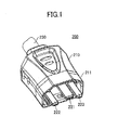
- FIG. 1 is a perspective view of the plug connector 200.
- FIG. 2 is a plan view of the plug connector 200.
- FIG. 3 is a side view of the plug connector 200.
- FIG. 4 is a bottom view of the plug connector 200.
- FIG. 5 is a front view of the plug connector 200.
- the plug connector 200 includes a cover portion 210 formed by insulating material or the like and three plug terminals 221, 222, and 223, which are examples of other connection terminals. On a side opposite to the side where the three plug terminals 221, 222, and 223 are provided, a power supply cable 230 is connected.
- the plug terminal 221 is a ground (GND) terminal, which is longer than the plug terminals 222 and 223. Electric power is supplied to the plug terminals 222 and 223 when the plug terminals 222 and 223 are electrically connected.
- the plug connector 200 includes a protecting portion 211 formed in a shape that covers the plug terminals 221, 222, and 223 in the cover portion 210 on a side provided with the plug terminals 221, 222, and 223. Further, a connector connection hole 212 is provided so that connector connection is not released after the plug connector 200 is connected to the connector of the first embodiment are connected.
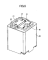
- FIG. 6 is a perspective view of a connector of the first embodiment.
- FIG. 7 is a front view of the connector.
- FIG. 8 is a side view of the connector.
- the connector of the first embodiment is entirely covered by a casing 50 and includes jack openings 21, 22, and 23 into which plug terminals 221, 222, and 223 of the plug connector 200 are inserted, a groove portion 31 into which the protecting portion 211 of the plug connector 200 is inserted, and a slide operating portion 40 for controlling whether electric power is supplied while the plug connector is connected to the connector of the first embodiment.
- the slide operation portion 40 can be slide into a position of "ON” or a position of "OFF". By sliding the slide operating portion 40, it is possible to control whether to supply electric power via the connector.
- FIG. 9 is a cross-sectional view for illustrating an internal structure of the connector of the first emb.
- the connector of the first embodiment is shaped such that the upper slide operating portion 40a of the slide operating portion 40 outwardly protrudes from an opening provided in the casing 50. By moving the upper slide operating portion 40a in a sliding direction indicated by an arrow A from the outside of the casing 50, it is possible to operate whether to electrically connect a switch portion 100 located inside the casing 50.
- the slide operating portion 40 has a main slide operating portion 40b positioned inside the casing 50.
- the main slide operating portion 40b is connected to a slide linking portion 41.
- the slid linking portion 41 is operated substantially in parallel to the sliding direction indicated by arrows A.
- the slide linking portion 41 is shaped like a letter of L.
- One end of the slide linking portion 41 intrudes inside a contact slide opening portion 42a of a contact slide portion 42.
- the contact slide opening portion 42a is formed to be an elongated shape along a moving direction of the slide linking portion 41, namely in the direction of the arrows A.
- a contact slide contacting portion extending in a direction substantially perpendicular to the sliding direction indicated by the arrows A is provided in the contract slide portion 42.
- the tip end of the contact slide contacting portion contacts the upper surface of the button 160 of the switch portion 100.
- the switch portion 100 of the connector of the first embodiment is to control supply of electric power.
- the switch portion 100 is referred to as a power source switch.
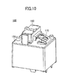
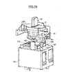
- FIG. 10 is a perspective view of the switch portion 100.
- FIG. 11 is an internal structural view of the switch portion 100. Referring to FIG. 11 , the switch portion 100 can control turning on or turning off the supply of electric power source depending on whether a fixed contact 111 of a fixed portion 110 contacts a movable contact 121 of a movable portion 120.
- the fixed portion 110 is entirely made of conductive material such as a metal.
- the fixed contact 111 capable of contacting the movable contact 121 of the movable portion 120 is provided in an end portion of the fixed spring 112.
- the fixed spring 112 is formed by bending a metallic plate made of copper, an alloy containing copper, or the like.
- the fixed contact 111 is made of an alloy containing silver and copper.
- Another end portion of the fixed spring 112 is fixed to a main base block 131 in the base block 130, and is supported by a fixing portion supporter 132 in a middle of the fixed spring 112.
- the movable portion 120 is entirely formed by conductive material such as a metal.
- the movable contact 121 capable of contacting the fixed contact 111 of the fixed portion 110 is provided in one end portion of the movable plate 122, and another end portion of the movable plate 122 is connected to one end portion of a movable spring 123.
- the movable plate 122 and the movable spring 123 are formed by bending a metallic plate made of copper, an alloy containing copper, or the like.
- the movable contact 121 is made of an alloy containing silver and copper.
- the other end portion of the movable spring 123 is fixed to the main base block 131 of the base block 130.
- the movable spring 123 is formed by bending a metallic plate or the like, the movable spring 123 has flexibility. Therefore, the movable contact 121 provided in the one end portion of the movable plate 122 can be moved up and down.
- an insulating wall 133 made of flame resistant resin material or the like is provided between a portion of the base block 130 where the other end portion of the fixed spring 112 is connected and a portion of the base block 130 where the other end portion of the movable spring 123 is connected.
- the movable spring 123 is bent so as to surround a part of the periphery of the insulating wall 133 from the other end portion.
- the upper surface of the movable plate 122 of the movable portion 120 contacts an upper contact part 141 of a card 140, which is an example of a first contact portion.
- the lower surface of the movable plate 122 of the movable portion 120 contacts a lower contact part 142 of the card 140 which is an example of a second contact portion.
- force is applied to the movable plate 122 by a contact of the movable plate 122 with the upper contact part 141 or the lower contact part 142, and the movable contact 121 can be upwardly or downwardly moved.
- a surface layer made of a fluorine resin may be formed on the surfaces of the upper contact part 141 and the lower contact part 142 in order to reduce a friction resistance.
- the fixed portion 110 and the movable portion 120 are installed inside an area surrounded by the base block 130 and a switch case 150.
- the card 140 includes a protruding portion 144 outwardly protruding from the switch opening 151 which is provided in the switch case 150, and a card main body 145 positioned inside,the area surrounded by the base block 130 and the switch case 150. Therefore, in the switch portion 100, the upper contact part 141 and the lower contact part 142 is provided inside the area surrounded by the base block 130 and the switch case 150. Further, the card 140, the base block 130, and the switch case 150 are formed by insulating material made of resin material or the like.
- a button 160 to rotate the card 140 around the rotating shaft 143 is provided outside the switch case 150.
- the card 140 contacts a button inner portion 161 of the button 160 at a contact portion 144a provided at the upper portion of the protruding portion 144 of the card 140. Because the contact portion 144a slides on the surface of the button inner portion 161, a surface layer made of a fluorine resin or the like may be formed on the surface of the button inner portion 161 in order to reduce the friction resistance.
- a swing spring 170 is provided outside the switch case 150. One end of the swing spring 170 is connected to the switch case 150 and the other end of the swing spring 170 is connected to the button 160.
- a contact slide contacting portion of the contact slide portion 42 is moved as described later.
- the button 160 is pushed down to push the card 140 whose contact portion 141 contacts the button inner portion 161 of the button. Therefore, the card 140 rotates along the rotating shaft 143.
- force is downwardly applied to the movable plate 122 of the movable portion 120 via the upper contact part 141 to cause the movable contact 121 to contact the fixed contact 111.
- This state is illustrated in FIG. 12 .
- this state of the switch portion 100 is maintained by the contact slide contacting portion of the contact slide portion 42, a contact between the movable contact 121 and the fixed contact 111 is maintained to enable the power source to supply the electric power.
- the contact slide contacting portion of the contact slide portion 42 is moved to return the button 160 to the turn-off state by restoring force of the swing spring 170.
- the card 140 in contact with the button inner portion 161 of the button 160 at the contact portion 141 is rotated around the rotating shaft 143.
- Force is upwardly applied to the movable plate 122 of the movable portion 120 via the lower contact part 142. As described, it becomes possible to cancel the contact between the movable contact 121 and the fixed contact 111 by the upward force applied to the movable plate 122 and the electric power supply from the electric power source stops.
- arc may be generated between the movable contact 121 and the fixed contact 111.
- a permanent magnet 180 for generating a magnetic field in a direction substantially perpendicular to the direction of generating the arc is provided in the vicinity of the position where the movable contact 121 contacts the fixed contact 111.
- the restoring force of the swing spring 170 provided outside the switch case 150 is used to change the switch portion 100 into the turn-off state. Therefore, in a case where the movable spring 123 of the movable portion 120 or the like does not have restoring force, the electric power source can be turned off. Further, if a part of the movable spring 123 or the like is molten by heat and the function as the spring is lost in the movable spring 123, the electric power source is made the turned-off state by spring property of the swing spring 170, without using the restoring force of the movable spring 123.
- the electric power supply from the electric power source can be securely shut down.
- the swing spring 170 is installed outside the switch case 150, the swing spring 170 is not influenced by heat or the like unlike the fixed portion 110 and the movable portion 120, which can be influenced by heat or the like inside the switch case 150.
- the insulating wall 133 is provided between the portion to which the other end portion of the fixed spring 112 is connected and the portion to which the other end portion of the movable spring 123 is connected.
- the switch portion 100 if a dust or the like intrudes into an area surrounded by the base block 130 and the switch case 150, a short circuit or a contact failure between the fixed contact 111 and the movable contact 121 may be caused. Therefore, in the turn-off state of the switch portion 100, in order to prevent the dust or the like from intruding into the area surrounded by the base block 130 and the switch case 150, the upper surface of the card main body 145 of the card 140 contacts the switch case 150 with pressure so as to close up the switch opening 151 of the switch case 150. With this, in the turn-off state of the switch portion 100, it is possible to prevent the dust or the like from intruding into the inside of the switch case 150 from the switch opening 151.
- a cover portion 152 provided in the vicinity of the switch opening 151 of the switch case 150 and a button end portion 162 in a U-like shape provided in the button 160 are provided.
- the button end portion 162 in the U-like shape of the button 160 covers the cover portion 152 of the switch case 150. Therefore, the switch opening 151 may be closed up by the cover portion 152 and the button end portion 162. With this, in the turn-on state of the switch portion 100, it is possible to prevent the dust or the like from intruding into the inside of the switch case 150 from the switch opening 151.
- the switch portion 100 can be turned on or off to enable to control the electric power supply from the electric power source or the like.
- the connector and the plug connector 200 are connected as illustrated in FIG. 14 from the state where the connector of the first embodiment is not connected to the plug connector 200 as illustrated in FIG. 13 .
- the upper slide operating portion 40a of the slide operating portion 40 of the connector of the first embodiment is in a position of "OFF", and the connector is in the turn-off state. Therefore, the connector and the plug connector are not electrically connected and electric power or the like is not supplied via the connector.
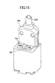
- the upper slide operating portion 40a of the slide operating portion 40 of the connector of the first embodiment is slid to the position of "ON" to change the connector to be in the turn-on state.
- the connector of the first embodiment and the plug connector 200 are electrically connected to enable supplying electric power via the connector.
- a transition from the turn-off state illustrated in FIG. 14 to the turn-on state illustrated in FIG. 15 is described in detail.
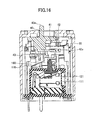
- FIG. 16 is an internal structural view viewed from a side surface of the connector of the first embodiment in the turn-off state.
- FIG. 17 is an internal structural view viewed from the upper surface of the connector of the first embodiment.
- FIG. 18 is a perspective view of a part of the internal structure of the connector of the first embodiment.
- FIG. 19 is a perspective view of a portion of a mechanical portion.
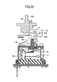
- FIG. 20 is a side view of the internal structure.
- the contact slide portion 42 includes a contact slide contacting portion 42b extending in a direction substantially perpendicular to sliding directions illustrated in arrows A. An end of the contact slide contacting portion 42b contacts a button bottom portion 163 of a groove formed on the upper surface of the button 160.
- Jack terminals 61, 62, and 63 to be electrically connected to the plug terminals 221, 222, and 223 are provided inside the jack openings 21, 22, and 23 of the connector of the first embodiment.
- the switch portion 100 contains two pairs of the fixed portion 110 and the movable portion 120 corresponding to the jack terminals 62 and 63. Said differently, the jack terminal 62 is connected to any one of the fixed and movable portions 110 and 120 of any one pair of the pairs of the fixed portion 110 and the movable portion 120, and the other one of the fixed and movable portions 110 and 120 is connected to an electric power source (not illustrated).
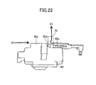
- the jack terminal 63 is connected to one of the fixed and movable portions 110 and 120 of the other pair of the pairs of the fixed portion 110 and the movable portion 120, and the other one of the fixed and movable portions 110 and 120 is connected to an electric power source (not illustrated). Further, a hook 70 illustrated in FIG. 22 contacts a narrow portion 40c in a side surface of the slide operating portion 40. Under this state, because the hook 70 is not inserted into the connector connection hole 212 of the plug connector 200, the connector of the first embodiment can be attached to or detached from the plug connector 200.
- FIG. 23 is an internal structural view viewed on the side surface side of the connector of the first embodiment under this state.
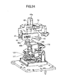
- FIG. 24 is a perspective view of a portion of a mechanical part.
- FIG. 25 is a side view of a portion of an internal structure. Under this state, the upper slide operating portion 40a is substantially at a middle position between the position of "ON" and the position of "OFF".
- One end of the L-shaped slide linking portion 41 contacts the right side of the contact slide opening portion 42a of the contact slide portion 42 to slightly move the contact slide portion 42 in the sliding direction.
- FIG. 26 is an internal structural view viewed from a side surface of the connector of the first embodiment in this turn-on state.
- FIG. 27 is an internal structural view viewed from the upper surface of the connector of the first embodiment.
- FIG. 28 is a perspective view of a part of the internal structure of the connector of the first embodiment.
- FIG. 29 is a perspective view of a portion of a mechanical portion.
- FIG. 30 is a side view of the internal structure.
- the upper slide operating portion 40a is at a position of "ON”.
- the right side of the contact slide opening portion 42a of the contact slide portion 42 is further pushed by the one end of the L-shaped slide linking portion.
- the contact slide portion 42 is further moved in this direction. With this, the end of the contact slide contacting portion 42b of the contact slide portion 42 contacts a button upper stage portion 165 provided in the button 160. Under this state, because the button 160 of the switch portion 100 is pushed by the contact slide contacting portion 42b, the fixed contact 111 of the fixed portion 110 contacts the movable contact 121 of the movable portion 120. This turn-on state is maintained by the contact between the button upper portion 165 of the button 160 and the end of the contact slide contacting portion 42b of the contact slide portion 42.
- the position of the side surface of the slide operating portion 40, in which the hook 70 illustrated in FIG. 22 contacts changes from the narrow portion 40c on the side surface of the slide operating portion 40 to a wide portion 40e via a slant portion 40d.
- the hook 70 is moved in a direction along an arrow B1, which is substantially perpendicular to the sliding direction. Because the moved hook 70 is inserted into the connector connection hole 212 provided in the plug connector 200 so as to be engaged with the connector connection hole 212, a connection between the connector of the first embodiment and the plug connector is maintained.
- the position of the upper slide operating portion 40a of the connector of the first embodiment is slid from the position "ON" to the position "OFF".
- the position where the end of the contact slide contacting portion 42b of the contact slide portion 42 contacts is moved from the button upper stage portion 165 of the button 160 to the button bottom portion 163 via the button slant portion 164.
- the button 160 is lift up by the swing spring 170 to release the contacts between the fixed contact 111 and the movable contact 121 of each pair of the fixed portion 110 and the movable portion 120.
- the switch portion becomes the turn-off state.
- the position of the side surface of the slide operating portion 40 that the hook 70 contacts is moved from the wide portion 40e on the side surface of the slide operating portion 40 to the narrow portion 40c via the slant portion 40d.
- the hook 70 moves outward from the inside of the connector connection hole 212 of the plug connector 200 to thereby enable the plug connector 200 being disconnected from the connector of the first embodiment.
- the switch of the second embodiment corresponds to the switch portion of the first embodiment.
- the switch is described in more detail.
- a commercially available switch may not shut down electric power supply. This phenomenon may be caused when contacting contacts are molten by heat caused by any reason because the voltage is high or the direct current is used. If such a phenomenon is caused, the function as the switch is completely lost to influence the electric power supply. Therefore, there occurs a problem in the function of the switch.
- the switch of the second embodiment is used to control supply of electric power.
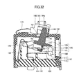
- the switch is referred to as a power source switch. Referring to FIG. 31 , the switch can control ON or OFF of the power supply from the electric power source depending on whether the fixed contact 111 of the fixed portion 110 contacts the movable contact 121 of the movable portion 120.
- the fixed portion 110 is entirely made of conductive material such as a metal.
- the fixed contact 111 capable of contacting the movable contact 121 of the movable portion 120 is provided in an end portion of the fixed spring 112.
- the fixed spring 112 is formed by bending a metallic plate made of copper, an alloy containing copper, or the like.
- the fixed contact 111 is made of an alloy containing silver and copper.
- the other end portion of the fixed spring 112 is fixed to the main base block 131 in the base block 130, and is supported by the fixing portion supporter 132 in a middle of the fixed spring 112.
- the movable portion 120 is entirely formed by conductive material such as a metal.
- the movable contact 121 capable of contacting the fixed contact 111 of the fixed portion 110 is provided in the one end portion of the movable plate 122, and the other end portion of the movable plate 122 is connected to the one end portion of the movable spring 123.
- the movable plate 122 and the movable spring 123 are made of a metallic plate made of copper, an alloy containing copper, or the like.
- the movable contact 121 is made of an alloy containing silver and copper.
- the other end portion of the movable spring 123 is fixed to the main base block 131 of the base block 130.
- the movable spring 123 is formed by bending a metallic plate or the like, the movable spring 123 has flexibility. Therefore, the movable contact 121 provided in the one end portion of the movable plate 122 can be moved up and down.
- the insulating wall 133 made of flame resistant resin material or the like is provided between a portion where the other end portion of the fixed spring 112 is connected and a portion where the other end portion of the movable spring 123 is connected.
- the movable spring 123 is bent so as to surround a part of the periphery of the insulating wall 133 from the other end portion.
- force is applied by the contact of the movable plate 122 with the upper contact part 141 or the lower contact part 142 thereby upwardly or downwardly moving the movable contact 121. Because the upper contact part 141 and the lower contact part 142 slide on the movable plate 122, the surface layer made of a fluorine resin may be formed on the surfaces of the upper contact part 141 and the lower contact part 142 in order to reduce the friction resistance.
- the fixed portion 110 and the movable portion 120 are installed inside the area surrounded by the base block 130 and the switch case 150.
- the card 140 includes the protruding portion 144 outwardly protruding from the switch opening 151, which is provided in the switch case 150, and the card main body 145 positioned inside the area surrounded by the base block 130 and the switch case 150. Therefore, in the switch, the upper contact part 141 or the lower contact part 142 is provided inside the area surrounded by the base block 130 and the switch case 150. Further, the card 140, the base block 130, and the switch case 150 are formed by insulating material made of resin material or the like.
- the button 160 is provided to rotate the card 140 around the rotating shaft 143.
- the card 140 contacts the button inner portion 161 of the button 160 at the contact portion 144a provided at the upper portion of the protruding portion 144 of the card 140. Because the contact portion 144a slides on the surface of the button inner portion 161, the surface layer made of a fluorine resin or the like may be formed on the surface of the button inner portion 161 in order to reduce the friction resistance.
- the swing spring 170 is provided outside the switch case 150. One end of the swing spring 170 is connected to the switch case 150 and the other end of the swing spring 170 is connected to the button 160.
- the switch of the second embodiment if the switch is turned on, the button 160 is pushed. Then, the card 140 contacting the button inner portion 161 of the button 160 at the contacting portion 144a rotates around the rotating shaft 143. Therefore, force is applied downwardly to the movable plate 122 of the movable portion 120 by the upper contact part 141 to thereby make the movable contact come into contact with the fixed contact. This state is illustrated in FIG. 32 .
- a turn-on state retaining mechanism or the like (not illustrated) having a locking portion or the like for maintaining the contact between the movable contact and the fixed contact is provided. By the turn-on state retaining mechanism or the like, the contact between the movable contact 121 and the fixed contact is maintained to continue the electric power supply from the electric power source.
- the switch of the second embodiment if the switch is turned off, the locking portion of the turn-on state retaining mechanism (not illustrated) or the like is released thereby turning off the switch by the restoring force caused by the spring property of the swing spring 170.
- the card 140 in contact with the button inner portion 161 of the button 160 at the contact portion 144a is rotated around the rotating shaft 143. Force is upwardly applied to the movable plate 122 of the movable portion 120 via the lower contacting part 142. As described, it becomes possible to cancel the contact between the movable contact 121 and the fixed contact 111 by the upward force applied to the movable plate 122 thereby stopping the electric power supply from the electric power source.
- arc may be generated between the movable contact 121 and the fixed contact 111.
- a permanent magnet 180 for generating a magnetic field in a direction substantially perpendicular to the direction of generating the arc is provided in the vicinity of the position where the movable contact 121 contacts the fixed contact 111.
- the switch when the electric power supply from the electric power source is shut down, instead of using the restoring force of the movable spring 123 of the movable portion 120 or the like, the restoring force of the swing spring 170 provided outside the switch case 150 is used to change into the turn-off state. Therefore, in a case where the restoring force is not accumulated by the movable spring 123 of the movable portion 120 or the like, the electric power source can be turned off.
- the electric power source is made the turned-off state by spring property of the swing spring 170.
- the electric power supply from the electric power source can be securely shut down.
- the swing spring 170 is installed outside the switch case 150, the swing spring 170 is not influenced by heat or the like unlike the fixed portion 110 and the movable portion 120, which are influenced by heat or the like inside the switch case 150.
- the insulating wall 133 is provided between the portion, to which the other end portion of the fixed spring 112 is connected and the portion, to which the other end portion of the movable spring 123 is connected.
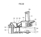
- the card 140 includes a rotating portion 146 in a circular shape, whose center matches the rotating shaft 143.
- the base block includes a card supporting portion 134 for connecting the card 140.
- the card supporting portion 134 has an opening portion 135 in a circular shape so that the rotating portion 146 of the card 140 is inserted. By inserting the rotating portion 146 into the opening portion 135, the card 140 is connected to the card supporting portion 134 so that the card 140 is rotatable around the rotating shaft 143.
- the card 140 is provided along the movable plate 122 while the upper contact part 141 contacts the upper side of the movable plate 122 and the lower contact part 142 contacts the lower side of the movable plate 122.
- the card 140 is moved until the rotating portion 146 is inserted inside the opening portion 135 and then is assembled.
- the movable portion 120, the base block 130, and the card 140 are connected.
- the rotating portions 146 of the card 140 are provided in end portions of each of two rods 147 so that the rotating portions 146 outwardly face.
- the two rods 147 is bent inwardly to insert the rotating portions 146 into the opening portions 135 of the base block 130.
- Parts of the opening portions 135 and parts of the rotating portions 146, which mutually contact, are processed with mirror-like finishing so that a friction resistance is reduced.
- the card supporting portion 134 includes guides 136 formed along a direction of inserting the rotating portions 146. Further, slant portions 137 are formed in the end portions of the card supporting portions 134 from which the rotating portions 146 are inserted therebetween.
- the movable plate 122 is interposed between the upper contact part 141 and the lower contact part 142.
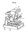
- a T-shaped opening 122a may be formed in the movable plate 122, and a protruding connecting portion 148 may be formed instead of the upper contact part 141 and the lower contact part 142.
- the protruding connecting portion 148 includes an end portion 148a gradually sharpened to a tip, a narrow portion 148b adjacent to the end portion 148a and having a smaller width, and a body portion 148c adjacent to the narrow portion 148b and having a greater width.
- the end portion 148a and the narrow portion 148b of the protruding connecting portion 148 are inserted into the opening 122a formed in the movable plate 122.
- the lower surface of the movable plate 122 is fixed between the narrow portion 148b and the end portion 148a wider than the narrow portion 148b.
- the upper surface of the movable plate 122 is fixed between the narrow portion 148b and the body portion 148c wider than the narrow portion 148b.
- the switch of the second embodiment in a case where a dust or the like intrudes into an area surrounded by the base block 130 and the switch case 150, a short circuit or a contact failure may be caused between the fixed contact 111 and the movable contact 121. Therefore, in the turn-off state of the switch of the second embodiment, referring to FIG. 37 , the upper surface of the card main body 145 of the card 140 contacts with pressure on an inner surface of the switch case 150 where the switch opening 151 is formed in order to prevent a dust or the like from intruding into the area surrounded by the base block 130 and the case 150. With this, in the turn-off state of the switch, it is possible to prevent the dust or the like from intruding into the inside of the switch case 150 from the switch opening 151.
- a cover portion 152 provided in the vicinity of the switch opening 151 of the switch case 150 and the button end portion 162 in the U-like shape provided in the button 160 are provided.
- the button end portion 162 in the U-like shape of the button 160 covers the cover portion 152 of the switch case 150. Therefore, the switch opening 151 may be closed up by the cover portion 152 and the button end portion 162. With this, in the turn-on state of the switch, it is possible to prevent the dust or the like from intruding into the inside of the switch case 150 from the switch opening 151.
- the number of the fixed contacts 111 and the number of the movable contacts may be plural.
- power supply to a plurality of electronic apparatuses or a plurality of electric circuits may be simultaneously changed to the turn-on state or the turn-off state.
- the plurality of fixed contacts 111 and the plurality of movable contacts 121 may be simultaneously the turn-on state or the turn-off state.
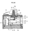
- FIG. 40 the turn-off state is illustrated in FIG. 40 and the turn-on state is illustrated in FIG. 41 .
- the switch of the third embodiment includes a card 340 having no rotating shaft.
- the card 340 moves up or down to causing the fixed contact 111 of the fixed portion 110 to contact the movable contact 121 of the movable portion 120.
- a contact portion 344a in contact with the button inner portion 161 of the button 160 is pushed.
- the card 340 moves downwardly.
- an upper contact part 341 pushes the movable plate 122 downwardly to make the fixed contact 111 contact the movable contact 121.
- the switch becomes the turn-on state.
- a turn-on state retaining mechanism or the like maintains the contact between the movable contact 121 and the fixed contact 111.
- the turn-on state retaining mechanism or the like when the turn-on state retaining mechanism or the like is released, restoring force of the swing spring 170 makes the switch be the turn-off state as illustrated in FIG. 40 .
- the lower contact part 342 of the card 340 pushes the movable plate 122 upwardly to release the contact between the fixed contact 111 and the movable contact 121. Because the upper contact part 341 and the lower contact part 342 slide on the movable plate 122, the surface layer made of the fluorine resin may be formed on the surfaces of the upper contact part 341 and the lower contact part 342 in order to reduce the friction resistance.
- the switch of the third embodiment because the rotating shaft or the like is not provided in the card 340, the switch can be miniaturized.
- the other portions of the third embodiment are similar to those described in the second embodiment.
- the switch of the third embodiment can be used as the switch portion of the connector of the first embodiment.
- a part of the movable spring 123 is formed by a cable 423, which is an electric wire.
- the part corresponding to the movable spring 123 is formed by the cable 423.
- the cable 423 may be any as long as electric conductivity is given to. It is preferable to use a cable such as a woven cable because a flexible motion is obtainable. Further, coating may be provided on the surface of the cable 423. A part of the cable 423 having electric conductivity is connected to a terminal connecting portion 424 provided in the movable portion 420.
- the other portions of the fourth embodiment are similar to those described in the second and third embodiments.
- the switch of the fourth embodiment can be used as the switch portion of the connector of the first embodiment.
Landscapes
- Physics & Mathematics (AREA)
- Electromagnetism (AREA)
- Details Of Connecting Devices For Male And Female Coupling (AREA)
- Slide Switches (AREA)
Applications Claiming Priority (2)
| Application Number | Priority Date | Filing Date | Title |
|---|---|---|---|
| JP2010254259A JP5619576B2 (ja) | 2010-11-12 | 2010-11-12 | コネクタ及びスイッチ |
| PCT/JP2011/066308 WO2012063528A1 (ja) | 2010-11-12 | 2011-07-19 | コネクタ及びスイッチ |
Publications (3)
| Publication Number | Publication Date |
|---|---|
| EP2639896A1 true EP2639896A1 (de) | 2013-09-18 |
| EP2639896A4 EP2639896A4 (de) | 2014-03-26 |
| EP2639896B1 EP2639896B1 (de) | 2019-10-30 |
Family
ID=46050686
Family Applications (1)
| Application Number | Title | Priority Date | Filing Date |
|---|---|---|---|
| EP11839401.4A Active EP2639896B1 (de) | 2010-11-12 | 2011-07-19 | Verbinder und schalter |
Country Status (5)
| Country | Link |
|---|---|
| US (2) | US9225125B2 (de) |
| EP (1) | EP2639896B1 (de) |
| JP (1) | JP5619576B2 (de) |
| CN (1) | CN103222121B (de) |
| WO (1) | WO2012063528A1 (de) |
Cited By (1)
| Publication number | Priority date | Publication date | Assignee | Title |
|---|---|---|---|---|
| EP3255740A4 (de) * | 2015-02-06 | 2019-01-09 | Fujitsu Component Limited | Verbinder |
Families Citing this family (24)
| Publication number | Priority date | Publication date | Assignee | Title |
|---|---|---|---|---|
| JPH0812148B2 (ja) | 1986-12-29 | 1996-02-07 | 日本分光工業株式会社 | エリプソメ−タ |
| JP5619576B2 (ja) * | 2010-11-12 | 2014-11-05 | 富士通コンポーネント株式会社 | コネクタ及びスイッチ |
| JP5658825B2 (ja) * | 2011-08-11 | 2015-01-28 | 富士通コンポーネント株式会社 | コネクタ及びコネクタバー |
| US8680415B2 (en) * | 2012-04-16 | 2014-03-25 | Zippy Technology Corp. | Micro-switch employing lever principle |
| US8816230B2 (en) * | 2012-06-08 | 2014-08-26 | Zippy Technology Corp. | Micro-switch provided labor-saving switching |
| JP6161974B2 (ja) * | 2013-06-26 | 2017-07-12 | 富士通コンポーネント株式会社 | コネクタ |
| JP6306882B2 (ja) * | 2013-12-27 | 2018-04-04 | 富士通コンポーネント株式会社 | コネクタ |
| CN103943398B (zh) * | 2014-04-04 | 2017-05-17 | 余正明 | 一种长行程微动开关 |
| CN103928255B (zh) * | 2014-04-04 | 2017-11-10 | 余正明 | 一种长行程防水微动开关 |
| JP2016110833A (ja) * | 2014-12-05 | 2016-06-20 | 富士通コンポーネント株式会社 | コネクタ |
| US9666977B2 (en) | 2015-07-29 | 2017-05-30 | Abb Schweiz Ag | Direct current socket with direct current arc protection |
| EP3353862A1 (de) | 2015-09-24 | 2018-08-01 | ABB Schweiz AG | Gleitkontaktanordnung zur beschleunigung der relativen trenngeschwindigkeit zwischen stecker- und buchsenkontakten |
| JP6618816B2 (ja) * | 2016-01-22 | 2019-12-11 | 富士通コンポーネント株式会社 | コネクタ及びコネクタ装置 |
| JP6660190B2 (ja) * | 2016-01-22 | 2020-03-11 | 富士通コンポーネント株式会社 | スイッチ及びコネクタ |
| US10468818B2 (en) * | 2017-01-20 | 2019-11-05 | Philip Giampi | Magnetically activated power socket and plug combination |
| DE102017129515A1 (de) * | 2017-12-12 | 2019-06-13 | Johnson Electric Germany GmbH & Co. KG | Elektrischer Schalter |
| JP2020095834A (ja) * | 2018-12-11 | 2020-06-18 | 富士通コンポーネント株式会社 | コネクタ及びコネクタ装置 |
| TWI699799B (zh) * | 2019-11-21 | 2020-07-21 | 達方電子股份有限公司 | 按鍵結構 |
| CN212961458U (zh) * | 2020-07-16 | 2021-04-13 | 漳州立达信光电子科技有限公司 | 外置驱动及灯具 |
| CN112332251B (zh) * | 2020-11-23 | 2022-08-16 | 上海宝临电气集团有限公司 | 一种智能安全型开关柜 |
| JP7673578B2 (ja) | 2021-08-18 | 2025-05-09 | オムロン株式会社 | 電源コンセント |
| CN114706171B (zh) * | 2022-03-31 | 2023-04-07 | 江西明鸿光电科技有限公司 | 一种防脱落多芯保偏光纤连接器 |
| CN115377748B (zh) * | 2022-08-19 | 2023-04-14 | 深圳市天麟精密模具有限公司 | 一种汽车通讯信号连接器 |
| WO2024179476A1 (zh) * | 2023-02-28 | 2024-09-06 | 公牛集团股份有限公司 | 插座和电源连接器 |
Family Cites Families (16)
| Publication number | Priority date | Publication date | Assignee | Title |
|---|---|---|---|---|
| US2473848A (en) * | 1947-08-21 | 1949-06-21 | Westinghouse Electric Corp | Circuit breaker |
| GB1127673A (en) * | 1966-04-06 | 1968-09-18 | Burgess Products Co Ltd | Improvements relating to electrical microswitches |
| US3648004A (en) * | 1971-02-25 | 1972-03-07 | Cutler Hammer Inc | Auxiliary support means for electrical switch actuator |
| JPH039365U (de) * | 1989-06-16 | 1991-01-29 | ||
| US5270505A (en) * | 1989-12-18 | 1993-12-14 | Joseph Magiera | Remote controlled switch/receptacle |
| JPH0582208A (ja) * | 1991-09-20 | 1993-04-02 | Fujitsu Ltd | コネクタ |
| JP3009365U (ja) * | 1994-07-25 | 1995-04-04 | キタノ製作株式会社 | 作動軸変換防水開閉装置 |
| JP3790450B2 (ja) * | 2001-07-17 | 2006-06-28 | 富士通アクセス株式会社 | 電気コネクタ |
| ITMI20012002A1 (it) * | 2001-09-27 | 2003-03-27 | Vimar Spa | Meccanismo di azionamento a compressione mediante tasto basculante diinterruttori commutatori deviatori e simili |
| JP2006351237A (ja) * | 2005-06-13 | 2006-12-28 | Alps Electric Co Ltd | スイッチ装置 |
| US7211758B2 (en) * | 2005-07-12 | 2007-05-01 | Defond Components Limited | Circuit interrupter that produces snap-action connection and disconnection between electrical contacts |
| JP4779892B2 (ja) * | 2006-09-06 | 2011-09-28 | オムロン株式会社 | スイッチおよび接点モジュール |
| JP5119113B2 (ja) * | 2008-07-30 | 2013-01-16 | 富士通コンポーネント株式会社 | 雄コネクタ、雌コネクタ及びコネクタ |
| JP2010257601A (ja) * | 2009-04-21 | 2010-11-11 | Alps Electric Co Ltd | 可動接点付きシートおよびプッシュスイッチ |
| JP5347689B2 (ja) | 2009-04-28 | 2013-11-20 | トヨタ自動車株式会社 | ブレーキ制御装置 |
| JP5619576B2 (ja) * | 2010-11-12 | 2014-11-05 | 富士通コンポーネント株式会社 | コネクタ及びスイッチ |
-
2010
- 2010-11-12 JP JP2010254259A patent/JP5619576B2/ja active Active
-
2011
- 2011-07-19 CN CN201180054302.1A patent/CN103222121B/zh active Active
- 2011-07-19 US US13/884,688 patent/US9225125B2/en active Active
- 2011-07-19 WO PCT/JP2011/066308 patent/WO2012063528A1/ja not_active Ceased
- 2011-07-19 EP EP11839401.4A patent/EP2639896B1/de active Active
-
2015
- 2015-11-18 US US14/944,415 patent/US9972460B2/en active Active
Cited By (2)
| Publication number | Priority date | Publication date | Assignee | Title |
|---|---|---|---|---|
| EP3255740A4 (de) * | 2015-02-06 | 2019-01-09 | Fujitsu Component Limited | Verbinder |
| EP3467961A1 (de) * | 2015-02-06 | 2019-04-10 | Fujitsu Component Limited | Verbinder |
Also Published As
| Publication number | Publication date |
|---|---|
| US9972460B2 (en) | 2018-05-15 |
| JP5619576B2 (ja) | 2014-11-05 |
| JP2012104448A (ja) | 2012-05-31 |
| US20130231007A1 (en) | 2013-09-05 |
| EP2639896A4 (de) | 2014-03-26 |
| WO2012063528A1 (ja) | 2012-05-18 |
| EP2639896B1 (de) | 2019-10-30 |
| US9225125B2 (en) | 2015-12-29 |
| US20160071663A1 (en) | 2016-03-10 |
| CN103222121A (zh) | 2013-07-24 |
| CN103222121B (zh) | 2016-04-20 |
Similar Documents
| Publication | Publication Date | Title |
|---|---|---|
| EP2639896B1 (de) | Verbinder und schalter | |
| JP5479036B2 (ja) | コネクタ装置、雌コネクタ、及び雄コネクタ | |
| JP5917853B2 (ja) | スイッチ及びコネクタ | |
| CN102956383B (zh) | 开关装置和连接器 | |
| US8878091B2 (en) | Switch device and connector | |
| JP5838056B2 (ja) | スイッチ及びコネクタ | |
| US9281635B2 (en) | Connector and connector bar | |
| JP6618816B2 (ja) | コネクタ及びコネクタ装置 | |
| JP5575504B2 (ja) | コネクタ装置、電源側コネクタ、及び電力供給ユニット | |
| US9653855B2 (en) | Connector and connector unit | |
| JP2011108397A (ja) | コネクタ装置、及び雄コネクタ | |
| JP6161974B2 (ja) | コネクタ | |
| JP6618817B2 (ja) | コネクタ | |
| US20180019553A1 (en) | Connector | |
| JP6660190B2 (ja) | スイッチ及びコネクタ |
Legal Events
| Date | Code | Title | Description |
|---|---|---|---|
| PUAI | Public reference made under article 153(3) epc to a published international application that has entered the european phase |
Free format text: ORIGINAL CODE: 0009012 |
|
| 17P | Request for examination filed |
Effective date: 20130605 |
|
| AK | Designated contracting states |
Kind code of ref document: A1 Designated state(s): AL AT BE BG CH CY CZ DE DK EE ES FI FR GB GR HR HU IE IS IT LI LT LU LV MC MK MT NL NO PL PT RO RS SE SI SK SM TR |
|
| DAX | Request for extension of the european patent (deleted) | ||
| A4 | Supplementary search report drawn up and despatched |
Effective date: 20140220 |
|
| RIC1 | Information provided on ipc code assigned before grant |
Ipc: H01R 13/713 20060101ALI20140214BHEP Ipc: H01H 15/16 20060101AFI20140214BHEP Ipc: H01R 13/70 20060101ALI20140214BHEP |
|
| STAA | Information on the status of an ep patent application or granted ep patent |
Free format text: STATUS: EXAMINATION IS IN PROGRESS |
|
| 17Q | First examination report despatched |
Effective date: 20170413 |
|
| GRAP | Despatch of communication of intention to grant a patent |
Free format text: ORIGINAL CODE: EPIDOSNIGR1 |
|
| STAA | Information on the status of an ep patent application or granted ep patent |
Free format text: STATUS: GRANT OF PATENT IS INTENDED |
|
| INTG | Intention to grant announced |
Effective date: 20190517 |
|
| GRAS | Grant fee paid |
Free format text: ORIGINAL CODE: EPIDOSNIGR3 |
|
| GRAA | (expected) grant |
Free format text: ORIGINAL CODE: 0009210 |
|
| STAA | Information on the status of an ep patent application or granted ep patent |
Free format text: STATUS: THE PATENT HAS BEEN GRANTED |
|
| RAP1 | Party data changed (applicant data changed or rights of an application transferred) |
Owner name: FUJITSU COMPONENT LIMITED Owner name: NTT FACILITIES, INC. |
|
| RIN1 | Information on inventor provided before grant (corrected) |
Inventor name: HIROSE, KEIICHI Inventor name: KIRYU, KOICHI Inventor name: IWAMOTO, DAIEI Inventor name: NORITAKE, MASATOSHI Inventor name: YUBA, TAKASHI Inventor name: BEAK, SEUNGSEOK |
|
| AK | Designated contracting states |
Kind code of ref document: B1 Designated state(s): AL AT BE BG CH CY CZ DE DK EE ES FI FR GB GR HR HU IE IS IT LI LT LU LV MC MK MT NL NO PL PT RO RS SE SI SK SM TR |
|
| REG | Reference to a national code |
Ref country code: GB Ref legal event code: FG4D |
|
| REG | Reference to a national code |
Ref country code: CH Ref legal event code: EP |
|
| REG | Reference to a national code |
Ref country code: AT Ref legal event code: REF Ref document number: 1197039 Country of ref document: AT Kind code of ref document: T Effective date: 20191115 |
|
| REG | Reference to a national code |
Ref country code: DE Ref legal event code: R096 Ref document number: 602011063101 Country of ref document: DE |
|
| REG | Reference to a national code |
Ref country code: IE Ref legal event code: FG4D |
|
| REG | Reference to a national code |
Ref country code: LT Ref legal event code: MG4D |
|
| PG25 | Lapsed in a contracting state [announced via postgrant information from national office to epo] |
Ref country code: SE Free format text: LAPSE BECAUSE OF FAILURE TO SUBMIT A TRANSLATION OF THE DESCRIPTION OR TO PAY THE FEE WITHIN THE PRESCRIBED TIME-LIMIT Effective date: 20191030 Ref country code: NL Free format text: LAPSE BECAUSE OF FAILURE TO SUBMIT A TRANSLATION OF THE DESCRIPTION OR TO PAY THE FEE WITHIN THE PRESCRIBED TIME-LIMIT Effective date: 20191030 Ref country code: LV Free format text: LAPSE BECAUSE OF FAILURE TO SUBMIT A TRANSLATION OF THE DESCRIPTION OR TO PAY THE FEE WITHIN THE PRESCRIBED TIME-LIMIT Effective date: 20191030 Ref country code: BG Free format text: LAPSE BECAUSE OF FAILURE TO SUBMIT A TRANSLATION OF THE DESCRIPTION OR TO PAY THE FEE WITHIN THE PRESCRIBED TIME-LIMIT Effective date: 20200130 Ref country code: FI Free format text: LAPSE BECAUSE OF FAILURE TO SUBMIT A TRANSLATION OF THE DESCRIPTION OR TO PAY THE FEE WITHIN THE PRESCRIBED TIME-LIMIT Effective date: 20191030 Ref country code: PT Free format text: LAPSE BECAUSE OF FAILURE TO SUBMIT A TRANSLATION OF THE DESCRIPTION OR TO PAY THE FEE WITHIN THE PRESCRIBED TIME-LIMIT Effective date: 20200302 Ref country code: GR Free format text: LAPSE BECAUSE OF FAILURE TO SUBMIT A TRANSLATION OF THE DESCRIPTION OR TO PAY THE FEE WITHIN THE PRESCRIBED TIME-LIMIT Effective date: 20200131 Ref country code: LT Free format text: LAPSE BECAUSE OF FAILURE TO SUBMIT A TRANSLATION OF THE DESCRIPTION OR TO PAY THE FEE WITHIN THE PRESCRIBED TIME-LIMIT Effective date: 20191030 Ref country code: NO Free format text: LAPSE BECAUSE OF FAILURE TO SUBMIT A TRANSLATION OF THE DESCRIPTION OR TO PAY THE FEE WITHIN THE PRESCRIBED TIME-LIMIT Effective date: 20200130 Ref country code: ES Free format text: LAPSE BECAUSE OF FAILURE TO SUBMIT A TRANSLATION OF THE DESCRIPTION OR TO PAY THE FEE WITHIN THE PRESCRIBED TIME-LIMIT Effective date: 20191030 Ref country code: PL Free format text: LAPSE BECAUSE OF FAILURE TO SUBMIT A TRANSLATION OF THE DESCRIPTION OR TO PAY THE FEE WITHIN THE PRESCRIBED TIME-LIMIT Effective date: 20191030 |
|
| REG | Reference to a national code |
Ref country code: NL Ref legal event code: MP Effective date: 20191030 |
|
| PG25 | Lapsed in a contracting state [announced via postgrant information from national office to epo] |
Ref country code: HR Free format text: LAPSE BECAUSE OF FAILURE TO SUBMIT A TRANSLATION OF THE DESCRIPTION OR TO PAY THE FEE WITHIN THE PRESCRIBED TIME-LIMIT Effective date: 20191030 Ref country code: RS Free format text: LAPSE BECAUSE OF FAILURE TO SUBMIT A TRANSLATION OF THE DESCRIPTION OR TO PAY THE FEE WITHIN THE PRESCRIBED TIME-LIMIT Effective date: 20191030 Ref country code: IS Free format text: LAPSE BECAUSE OF FAILURE TO SUBMIT A TRANSLATION OF THE DESCRIPTION OR TO PAY THE FEE WITHIN THE PRESCRIBED TIME-LIMIT Effective date: 20200229 |
|
| PG25 | Lapsed in a contracting state [announced via postgrant information from national office to epo] |
Ref country code: AL Free format text: LAPSE BECAUSE OF FAILURE TO SUBMIT A TRANSLATION OF THE DESCRIPTION OR TO PAY THE FEE WITHIN THE PRESCRIBED TIME-LIMIT Effective date: 20191030 |
|
| PG25 | Lapsed in a contracting state [announced via postgrant information from national office to epo] |
Ref country code: CZ Free format text: LAPSE BECAUSE OF FAILURE TO SUBMIT A TRANSLATION OF THE DESCRIPTION OR TO PAY THE FEE WITHIN THE PRESCRIBED TIME-LIMIT Effective date: 20191030 Ref country code: RO Free format text: LAPSE BECAUSE OF FAILURE TO SUBMIT A TRANSLATION OF THE DESCRIPTION OR TO PAY THE FEE WITHIN THE PRESCRIBED TIME-LIMIT Effective date: 20191030 Ref country code: DK Free format text: LAPSE BECAUSE OF FAILURE TO SUBMIT A TRANSLATION OF THE DESCRIPTION OR TO PAY THE FEE WITHIN THE PRESCRIBED TIME-LIMIT Effective date: 20191030 Ref country code: EE Free format text: LAPSE BECAUSE OF FAILURE TO SUBMIT A TRANSLATION OF THE DESCRIPTION OR TO PAY THE FEE WITHIN THE PRESCRIBED TIME-LIMIT Effective date: 20191030 |
|
| REG | Reference to a national code |
Ref country code: DE Ref legal event code: R097 Ref document number: 602011063101 Country of ref document: DE |
|
| REG | Reference to a national code |
Ref country code: AT Ref legal event code: MK05 Ref document number: 1197039 Country of ref document: AT Kind code of ref document: T Effective date: 20191030 |
|
| PG25 | Lapsed in a contracting state [announced via postgrant information from national office to epo] |
Ref country code: IT Free format text: LAPSE BECAUSE OF FAILURE TO SUBMIT A TRANSLATION OF THE DESCRIPTION OR TO PAY THE FEE WITHIN THE PRESCRIBED TIME-LIMIT Effective date: 20191030 Ref country code: SK Free format text: LAPSE BECAUSE OF FAILURE TO SUBMIT A TRANSLATION OF THE DESCRIPTION OR TO PAY THE FEE WITHIN THE PRESCRIBED TIME-LIMIT Effective date: 20191030 Ref country code: SM Free format text: LAPSE BECAUSE OF FAILURE TO SUBMIT A TRANSLATION OF THE DESCRIPTION OR TO PAY THE FEE WITHIN THE PRESCRIBED TIME-LIMIT Effective date: 20191030 |
|
| PLBE | No opposition filed within time limit |
Free format text: ORIGINAL CODE: 0009261 |
|
| STAA | Information on the status of an ep patent application or granted ep patent |
Free format text: STATUS: NO OPPOSITION FILED WITHIN TIME LIMIT |
|
| 26N | No opposition filed |
Effective date: 20200731 |
|
| PG25 | Lapsed in a contracting state [announced via postgrant information from national office to epo] |
Ref country code: SI Free format text: LAPSE BECAUSE OF FAILURE TO SUBMIT A TRANSLATION OF THE DESCRIPTION OR TO PAY THE FEE WITHIN THE PRESCRIBED TIME-LIMIT Effective date: 20191030 Ref country code: AT Free format text: LAPSE BECAUSE OF FAILURE TO SUBMIT A TRANSLATION OF THE DESCRIPTION OR TO PAY THE FEE WITHIN THE PRESCRIBED TIME-LIMIT Effective date: 20191030 |
|
| PG25 | Lapsed in a contracting state [announced via postgrant information from national office to epo] |
Ref country code: MC Free format text: LAPSE BECAUSE OF FAILURE TO SUBMIT A TRANSLATION OF THE DESCRIPTION OR TO PAY THE FEE WITHIN THE PRESCRIBED TIME-LIMIT Effective date: 20191030 |
|
| REG | Reference to a national code |
Ref country code: CH Ref legal event code: PL |
|
| REG | Reference to a national code |
Ref country code: BE Ref legal event code: MM Effective date: 20200731 |
|
| PG25 | Lapsed in a contracting state [announced via postgrant information from national office to epo] |
Ref country code: CH Free format text: LAPSE BECAUSE OF NON-PAYMENT OF DUE FEES Effective date: 20200731 Ref country code: LI Free format text: LAPSE BECAUSE OF NON-PAYMENT OF DUE FEES Effective date: 20200731 Ref country code: LU Free format text: LAPSE BECAUSE OF NON-PAYMENT OF DUE FEES Effective date: 20200719 |
|
| PG25 | Lapsed in a contracting state [announced via postgrant information from national office to epo] |
Ref country code: BE Free format text: LAPSE BECAUSE OF NON-PAYMENT OF DUE FEES Effective date: 20200731 |
|
| REG | Reference to a national code |
Ref country code: DE Ref legal event code: R082 Ref document number: 602011063101 Country of ref document: DE Representative=s name: HOFFMANN - EITLE PATENT- UND RECHTSANWAELTE PA, DE Ref country code: DE Ref legal event code: R081 Ref document number: 602011063101 Country of ref document: DE Owner name: NTT FACILITIES, INC., JP Free format text: FORMER OWNERS: FUJITSU COMPONENT LIMITED, TOKYO, JP; NTT FACILITIES, INC., TOKYO, JP Ref country code: DE Ref legal event code: R081 Ref document number: 602011063101 Country of ref document: DE Owner name: TERADA CO., LTD., JP Free format text: FORMER OWNERS: FUJITSU COMPONENT LIMITED, TOKYO, JP; NTT FACILITIES, INC., TOKYO, JP |
|
| REG | Reference to a national code |
Ref country code: GB Ref legal event code: 732E Free format text: REGISTERED BETWEEN 20210708 AND 20210714 |
|
| PG25 | Lapsed in a contracting state [announced via postgrant information from national office to epo] |
Ref country code: IE Free format text: LAPSE BECAUSE OF NON-PAYMENT OF DUE FEES Effective date: 20200719 |
|
| PG25 | Lapsed in a contracting state [announced via postgrant information from national office to epo] |
Ref country code: TR Free format text: LAPSE BECAUSE OF FAILURE TO SUBMIT A TRANSLATION OF THE DESCRIPTION OR TO PAY THE FEE WITHIN THE PRESCRIBED TIME-LIMIT Effective date: 20191030 Ref country code: MT Free format text: LAPSE BECAUSE OF FAILURE TO SUBMIT A TRANSLATION OF THE DESCRIPTION OR TO PAY THE FEE WITHIN THE PRESCRIBED TIME-LIMIT Effective date: 20191030 Ref country code: CY Free format text: LAPSE BECAUSE OF FAILURE TO SUBMIT A TRANSLATION OF THE DESCRIPTION OR TO PAY THE FEE WITHIN THE PRESCRIBED TIME-LIMIT Effective date: 20191030 |
|
| PG25 | Lapsed in a contracting state [announced via postgrant information from national office to epo] |
Ref country code: MK Free format text: LAPSE BECAUSE OF FAILURE TO SUBMIT A TRANSLATION OF THE DESCRIPTION OR TO PAY THE FEE WITHIN THE PRESCRIBED TIME-LIMIT Effective date: 20191030 |
|
| PGFP | Annual fee paid to national office [announced via postgrant information from national office to epo] |
Ref country code: FR Payment date: 20220531 Year of fee payment: 12 |
|
| PGFP | Annual fee paid to national office [announced via postgrant information from national office to epo] |
Ref country code: GB Payment date: 20220720 Year of fee payment: 12 |
|
| GBPC | Gb: european patent ceased through non-payment of renewal fee |
Effective date: 20230719 |
|
| REG | Reference to a national code |
Ref country code: DE Ref legal event code: R081 Ref document number: 602011063101 Country of ref document: DE Owner name: TERADA CO., LTD., JP Free format text: FORMER OWNERS: NTT FACILITIES, INC., TOKYO, JP; TERADA CO., LTD., TOKYO, JP |
|
| PG25 | Lapsed in a contracting state [announced via postgrant information from national office to epo] |
Ref country code: GB Free format text: LAPSE BECAUSE OF NON-PAYMENT OF DUE FEES Effective date: 20230719 |
|
| PG25 | Lapsed in a contracting state [announced via postgrant information from national office to epo] |
Ref country code: FR Free format text: LAPSE BECAUSE OF NON-PAYMENT OF DUE FEES Effective date: 20230731 |
|
| PGFP | Annual fee paid to national office [announced via postgrant information from national office to epo] |
Ref country code: DE Payment date: 20250728 Year of fee payment: 15 |