EP2640011B1 - Verfahren zum Transport von Echtzeit-Paketen - Google Patents
Verfahren zum Transport von Echtzeit-Paketen Download PDFInfo
- Publication number
- EP2640011B1 EP2640011B1 EP12305305.0A EP12305305A EP2640011B1 EP 2640011 B1 EP2640011 B1 EP 2640011B1 EP 12305305 A EP12305305 A EP 12305305A EP 2640011 B1 EP2640011 B1 EP 2640011B1
- Authority
- EP
- European Patent Office
- Prior art keywords
- output port
- ops
- transmission
- transmission schedule
- node
- Prior art date
- Legal status (The legal status is an assumption and is not a legal conclusion. Google has not performed a legal analysis and makes no representation as to the accuracy of the status listed.)
- Not-in-force
Links
- 238000000034 method Methods 0.000 title claims description 43
- 230000005540 biological transmission Effects 0.000 claims description 172
- 238000004891 communication Methods 0.000 claims description 40
- 238000011144 upstream manufacturing Methods 0.000 claims description 38
- 230000002123 temporal effect Effects 0.000 claims description 13
- 230000008707 rearrangement Effects 0.000 description 7
- 239000000872 buffer Substances 0.000 description 6
- 230000001934 delay Effects 0.000 description 6
- 238000010586 diagram Methods 0.000 description 5
- 230000009467 reduction Effects 0.000 description 4
- 230000011664 signaling Effects 0.000 description 4
- 238000013459 approach Methods 0.000 description 3
- 230000008901 benefit Effects 0.000 description 3
- 230000001360 synchronised effect Effects 0.000 description 3
- 230000006399 behavior Effects 0.000 description 2
- 238000007596 consolidation process Methods 0.000 description 2
- 238000005516 engineering process Methods 0.000 description 2
- 238000005457 optimization Methods 0.000 description 2
- 230000000737 periodic effect Effects 0.000 description 2
- 230000008569 process Effects 0.000 description 2
- 238000012545 processing Methods 0.000 description 2
- 238000009825 accumulation Methods 0.000 description 1
- 230000002776 aggregation Effects 0.000 description 1
- 238000004220 aggregation Methods 0.000 description 1
- 230000015556 catabolic process Effects 0.000 description 1
- 230000001427 coherent effect Effects 0.000 description 1
- 230000003247 decreasing effect Effects 0.000 description 1
- 238000006731 degradation reaction Methods 0.000 description 1
- 238000011161 development Methods 0.000 description 1
- 238000007689 inspection Methods 0.000 description 1
- 230000003993 interaction Effects 0.000 description 1
- 238000012423 maintenance Methods 0.000 description 1
- 238000013507 mapping Methods 0.000 description 1
- 230000002093 peripheral effect Effects 0.000 description 1
- 230000002441 reversible effect Effects 0.000 description 1
- 238000007619 statistical method Methods 0.000 description 1
- 239000002699 waste material Substances 0.000 description 1
Images

Classifications
-
- H—ELECTRICITY
- H04—ELECTRIC COMMUNICATION TECHNIQUE
- H04L—TRANSMISSION OF DIGITAL INFORMATION, e.g. TELEGRAPHIC COMMUNICATION
- H04L12/00—Data switching networks
- H04L12/28—Data switching networks characterised by path configuration, e.g. LAN [Local Area Networks] or WAN [Wide Area Networks]
- H04L12/40—Bus networks
- H04L12/40143—Bus networks involving priority mechanisms
- H04L12/4015—Bus networks involving priority mechanisms by scheduling the transmission of messages at the communication node
-
- H—ELECTRICITY
- H04—ELECTRIC COMMUNICATION TECHNIQUE
- H04L—TRANSMISSION OF DIGITAL INFORMATION, e.g. TELEGRAPHIC COMMUNICATION
- H04L12/00—Data switching networks
- H04L12/28—Data switching networks characterised by path configuration, e.g. LAN [Local Area Networks] or WAN [Wide Area Networks]
- H04L12/40—Bus networks
- H04L12/407—Bus networks with decentralised control
- H04L12/417—Bus networks with decentralised control with deterministic access, e.g. token passing
-
- H—ELECTRICITY
- H04—ELECTRIC COMMUNICATION TECHNIQUE
- H04L—TRANSMISSION OF DIGITAL INFORMATION, e.g. TELEGRAPHIC COMMUNICATION
- H04L47/00—Traffic control in data switching networks
- H04L47/10—Flow control; Congestion control
- H04L47/28—Flow control; Congestion control in relation to timing considerations
- H04L47/283—Flow control; Congestion control in relation to timing considerations in response to processing delays, e.g. caused by jitter or round trip time [RTT]
-
- H—ELECTRICITY
- H04—ELECTRIC COMMUNICATION TECHNIQUE
- H04L—TRANSMISSION OF DIGITAL INFORMATION, e.g. TELEGRAPHIC COMMUNICATION
- H04L47/00—Traffic control in data switching networks
- H04L47/10—Flow control; Congestion control
- H04L47/36—Flow control; Congestion control by determining packet size, e.g. maximum transfer unit [MTU]
-
- H—ELECTRICITY
- H04—ELECTRIC COMMUNICATION TECHNIQUE
- H04L—TRANSMISSION OF DIGITAL INFORMATION, e.g. TELEGRAPHIC COMMUNICATION
- H04L47/00—Traffic control in data switching networks
- H04L47/50—Queue scheduling
- H04L47/62—Queue scheduling characterised by scheduling criteria
- H04L47/625—Queue scheduling characterised by scheduling criteria for service slots or service orders
- H04L47/628—Queue scheduling characterised by scheduling criteria for service slots or service orders based on packet size, e.g. shortest packet first
Definitions
- the technical domain is the domain of communication networks, and particularly communication networks able to transport packets with stringent real-time constraints/requirements.
- the present application concerns a method to simultaneously reduce end-to-end latency, jitter and loss ratio of a real-time application traffic flow.
- a known method to reduce loss ratio is to over-provision the buffer size within network nodes. This avoids buffer over-flow, which is the main cause of loss.
- the buffer size increase leads to an increase of the end-to-end latency.
- a known method to optimize latency is to implement several qualities of service, QoS, with higher priorities assigned to the more demanding real-time applications.
- QoS qualities of service
- this method does not improve the jitter.
- a known method to optimize jitter is to implement delay equalization at each network node.
- the principle of such delay equalization consists in using delay lines to delay quicker packets of a delay up to the effective delay of the latest packet, in order to synchronize the quicker packets with respect to the latest packet.
- the introduction of delay lines increases latency. Moreover, this does not prevent packet losses.
- Some communication applications have more and more stringent real-time requirements.
- Some communication applications have more and more stringent real-time requirements.
- TDM time division multiplexing technology
- TDM can only accommodate a fix frame size. It is thus not applicable to most of nowadays applications, using variable size packets, such as e.g. TCP/IP protocols. Variable size packets can be converted to fix size packets but this needs additional processing and extra overhead leading to a waste of network resources.
- Document EP1786149 discloses transmission of status-information of a respective assigned packet queues to a central communicate unit and evaluating it centrally.
- a control message is sent to the peripheral communication unit, wherein the control message contains information for controlling the processing of the packet queues assigned to the logical connection.
- a method able to simultaneously reduce the three parameters, that is, end-to-end latency, jitter and loss ratio of a real-time traffic flow, applicable to variable packet sizes and also guaranteeing a deterministic behaviour is thus currently hardly expected.
- the object of the present application is a method, in a time-synchronized packet-switched communication network, for transporting packets from at least one source node to at least one destination node through at least one transit node, according to claim 1.
- a set of transmission instants is defined by a starting transmission instant and a period.
- output port schedulers of a same node collaborate during the building of a transmission schedule table for a common upstream link.
- each output port scheduler proposes a transmission schedule table to each of its adjacent downstream output port(s) scheduler.
- the building step when building a transmission schedule table for an output port scheduler, takes into account all packets competing for an output port associated to said output port scheduler, in order to avoid temporal conflict.
- the building step when building a transmission schedule table for an output port scheduler, takes into account any transmission delay occurring from said output port scheduler to its adjacent downstream output port scheduler.
- the building step when building a transmission schedule table for an output port scheduler, takes into account an overall delivering delay until source output port scheduler.
- the method further implements delay equalization at each node.
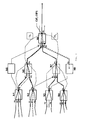
- Said communication network comprises a number of nodes Ni, here e.g. 9 nodes N1-N9.
- Said nodes N1-N9 may be parted into edge nodes N1-N4, N9 and inner or transit nodes N5-N8. Any given pair of nodes may be linked together by at least one link.
- Each node N1-N9 comprises at least one port Pj to interface some links, either as input port and/or as output port, depending on the direction of the traffic flow.
- a port Pj be it an input port or an output port may be referred to by the node Ni to which it belongs and its proper port reference Pj.
- the rightest port on the figure 1 may be referred to by N9-P6.
- a link may be referred to by its two extremity ports Pj.
- nodes N7 and N9 are linked by a single link N7-P4 / N9-P3.
- a traffic flow is transported through said communication network from one edge node, called a source node, to another edge node, called a destination node, through some inner nodes.
- said traffic flow is forwarded through nodes, by selecting, at each node Ni, a right output port Pj from said node Ni.
- a traffic flow enters the communication network through source (edge) node N1 by its (here input) port P1, thus N1-P1. It is then switched through said node N1 to its (here output) port P5, namely N1-P5. Through the associated link N1-P5 /N6-P1 said traffic flow is transported to (inner) node N6, which it enters through the (here input) port P1, namely N6-P1. The traffic flow is then switched through said node N6 to its (here output) port P4, namely N6-P4.
- the traffic flow is transported to the destination (edge) node N9, which it enters through the (here input) port P2, namely N9-P2. Said traffic flow exits the communication network through said destination (edge) node N9 by the (here output) port P6, namely N9-P6.
- the communication network where the method is to be implemented is advantageously a time-synchronized communication network.
- a time-synchronised communication network all nodes N1-N9 of the communication network share a common time reference.
- Such a feature is nowadays an emerging feature defined e.g. by standards such as ITU-T G.8271.1, G.8272, G.8273, G.8275.1.
- Such synchronisation may e.g. imply a shared absolute time reference between all nodes N1-N9 within an accuracy of less than 1 ⁇ s.
- Such a feature allows for a precise synchronisation between nodes, and thus for the scheduling of traffic flows to be switched across them.
- a traffic flow is an application related set of information.
- a traffic flow is a set of packets having in common some defined characteristics. It comprises packets, possibly of different packet sizes, sharing e.g. a common source, that is, an edge node from where said packets enter the communication network, and/or e.g. a common destination, that is, an edge node from where said packets exit the communication network, and/or a common type of service, TOS.
- a traffic flow may e.g. be a forwarding equivalence class, FEC, as specified within the MPLS framework. Since packets of a traffic flow are application related, they must also be transported in a given, relatively short, time interval.
- any given pair of traversed adjacent nodes is composed of an upstream node, the one closer to the traffic flow source node, and a downstream node, the one closer to the traffic flow destination node.
- a typical traffic flow may e.g. be a video stream.
- the main idea developed here is to provide a communication network with the advantages of a TDM protocol in term of reduction of latency, jitter and loss ratio, while being able to cope with packets of variable sizes.
- the method timely configures the communication network, for each output link related to an output port. This may advantageously be done on a traffic flow basis, along the whole path of a traffic flow, from the source node to the destination node, before the actual transport of said traffic flow across the network. By doing so, no temporal conflict will occur when the traffic flow is effectively sent across the communication network, and the transmission characteristics of the traffic flow are optimized.
- a given traffic flow comprises a temporal sequence of successive packets.
- Said traffic flow may be characterized by the sizes Si of said packets.
- the traffic flow comprises an amount of packets of said size. Since all packets of the traffic flow must be transmitted according to given time characteristics, said amount may be translated in a time load Ti, expressed e.g. as a throughput or a bandwidth or a frequency.
- Said time schedule shares the link bandwidth among the concurrent traffic flows using said link.
- Said time schedule may be built in the form of transmission schedule table TS comprising a set of n-uplets, each comprising a given size Si of packet and a set of transmission instants SIi.
- a transmission schedule table TS is defined for an output link and comprises for each needed size Si of packet, the set of transmission instants SIi in time where a packet of said size of packet Si may be sent over said output link.
- each transmission schedule table TS is delivered to an output port scheduler OPS, enabling the later to manage the transmission of all combined traffic flows without temporal conflicts over its associated output link.
- the scheduling treatment must done by any one of the two extremity ports of said link, advantageously the output port OP, which is upstream of said link, with respect to the direction of the traffic flow.
- Said output port OP then manages the scheduling over the link attached to said output port OP.
- a dedicated module, named an output port scheduler OPS in charge of the scheduling may be provided to each output port OP.
- An output port scheduler OPS could be a software, a hardware piece or a combination of both.
- An output port scheduler OPS is provided to each output port on each network node.
- Said output port scheduler OPS then receives the transmission schedule table TS built for its attached output link. Said output port scheduler OPS may then transmit packets over said output link, according to said transmission schedule table TS. That is, the output port scheduler OPS transmits a packet, according to its packet size Si, at a transmission instant from a set SIi associated to said packet size Si in said transmission schedule table TS.
- each packet to be transmitted find its temporal place and no conflict occurs since all the packet transmissions are temporally preconfigured before any sending.
- the usage of link bandwidth may be optimized. Conflicts that may result from packets competing for accessing a given link, in a prior art packet switched communication network, are here avoided by configuring in advance bandwidth allocations, according to a time schedule/transmission schedule table TS, for each link.
- a transmission schedule table TS associates a set of transmission instants SIi to a packet size Si.
- Said transmission instants may be ordered or not.
- at least some of said transmission instants ti are preferably defined in the future with respect to the current computing instant. If a transmission instant ti is defined in the past, with respect to the current time, it may simply be ignored. However such a past transmission instant ti is useless and should be avoided.
- Such a way of expressing a set of transmission instants SIi may become cumbersome when a transmission instant ti must be defined individually for each packet of said packet size Si.
- An alternate convenient way to express said set of transmission instants SIi may be by indicating a first initial transmission instant t0 and a frequency f or a period T, when a transmission of a packet of packet size Si occurs periodically. This is equivalent to provide the following list of transmission instants: ⁇ t0, t0+T, .., t0+i.T, .. ⁇ but advantageously takes far less memory space.
- the building step when building a transmission schedule table TS for one output port scheduler OPS, advantageously takes into account all packets competing for an output link associated to said output port scheduler OPS, that is, to the output link located downstream of the output port OP of said output port scheduler OPS, in order to avoid temporal conflict, between packets.
- the building step generally needs a view of traffic flows at a more global level than only at the output port or only at an output link level.
- a first way to get a more global level view may be a centralized way.
- a central managing module is in charge and run the building step for determining all the transmission schedule tables TS for all the output links of the communication network.
- Such a way of doing is possible and is advantageously located at a level sufficient to get all the needed information about traffic flow characteristics.
- such an approach might encounter scalability issue with communication network growing in size/number of nodes.
- Another way of doing said building step is to have a managing module responsible for each part of the communication network.
- the different managing modules, each responsible of a part, must then collaborate to compute the different TSs.
- a first upstream traffic consists of a part of the traffic coming from node N6, through link N6-P4/N9-P2. It is only a part, since said link N6-P4/N9-P2 also carries some traffic heading to output port N9-P4.
- a second upstream traffic consists of a part of the traffic coming from node N7, through link N7-P4/N9-P3. In the example, no other upstream traffic is heading to output port N9-P6.
- an output port scheduler OPS located at said output port N9-P6 is well positioned to build a time schedule for each of its upstream links N6-P4/N9-P2 and N7-P4/N9-P3 so that when all traffics heading to port N9-P6 are summed up to be transmitted over the output link outputting from output port N9-P6, the aggregation of all the upstream traffics/time schedules can be performed without conflict.
- An output port scheduler OPS has two roles. The first one consists in building TSs for its different adjacent upstream output port schedulers OPSs. The second one consists in applying the different TSs it has received from its downstream OPSs when transmitting/scheduling packets over its associated output link.
- an output port scheduler OPS is well positioned to build a transmission schedule table TS for each of its adjacent/neighbour upstream links, each output link being managed by its adjacent upstream output port scheduler OPS.
- the output port scheduler OPS of output port N9-P6 is advantageously in charge of building a transmission schedule table TS for its first adjacent upstream output port scheduler OPS in charge of output port N6-P4 and a transmission schedule table for its second adjacent upstream output port scheduler OPS in charge of output port N7-P4.
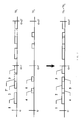
- Figure 2 illustrates, on temporal diagrams, some illustrative time schedules/transmission schedule tables TS and the notion of compatibility.
- the first top diagram illustrates, based on a periodic embodiment, a first time schedule derived from a first transmission schedule table TS1. It shows on each period T, three packets 1, 2, 3, temporally defined with respect to a periodic starting time t0, t0+T, t0+iT, etc. These packets 1-3 are not necessary of the same size, as illustrated.
- the second middle diagram illustrates, with the same temporal reference, a second time chart derived from a second transmission schedule table TS2.
- each period T two packets 4, 5, temporally defined with respect to the same starting period time t0, t0+T, t0+iT, etc.
- the time illustrated here is the packet arrival time at a given output port, e.g. N9-P6.
- a rearrangement may comprise temporally moving any packet inside a given period.
- a rearrangement may comprise fragmenting a packet into several parts inside a given period.
- packet 2 was initially defined as 2' instead, then packet 2' would obviously overlap with packet 5.
- Transmission schedule tables TS1, TS2, would not have been compatible and no merge would have been possible.
- a rearrangement consisting in moving packet 2' to the temporal location of packet 2 modifies the first transmission schedule table TS1, so that it becomes compatible with the second transmission schedule table TS2. No bandwidth use amendment is induced by such a rearrangement.
- an output port scheduler OPS may receive several transmission tables TS built by different downstream output port scheduler OPS.
- the output port scheduler OPS in N9-P6 builds a transmission schedule table TS for the traffic flow arriving at its output port N9-P6 and delivers said transmission schedule table TS to its adjacent upstream output port scheduler OPS in N6-P4.
- the output port scheduler OPS in N9-P4 builds another transmission schedule table TS for the traffic flow arriving at its output port N9-P4 and delivers said transmission schedule table TS to its adjacent upstream output port scheduler OPS that appears to be the same output port scheduled located in N6-P4.
- Such a situation implies that said several transmission schedule tables TS corresponding to a same output link and thus delivered to a same output port scheduler OPS must be compatible.
- Said compatibility as illustrated in figure 2 , mean that said several transmission schedule tables TS must not be temporally overlapping each other, so that the corresponding traffic flows can be forwarded to the same output port OP and be transported over the same output link they share without any conflict.
- the output port scheduler OPS in output port N9-P6 and the output port scheduler OPS in output port N9-P4 must cooperate when each of them builds a transmission schedule table TS for their common adjacent upstream output port scheduler OPS in charge of the output port N6-P4.
- both transmission schedule tables TS so built, and received by the adjacent upstream output port scheduler OPS in N6-P4 are assured to be compatible, meaning not to be temporarily overlapping each other.
- each output port scheduler OPS may thus build a transmission schedule table TS for each of its adjacent upstream link(s) and delivers said transmission schedule table(s) TS to said each adjacent upstream output port scheduler(s) OPS.
- Each of said adjacent upstream output port(s) scheduler OPS receives possibly several transmission schedule tables TS coming from its downstream output port scheduler(s) and in case consolidates them.
- said adjacent upstream output port scheduler OPS then builds a transmission schedule table TS for each of its related adjacent upstream link(s) and delivers the later to its related adjacent upstream output port scheduler OPS.
- Said process is recursively applied upstream until reaching an edge node, that is here considered to be a source node for the given traffic flows.
- the whole network may be configured by building and delivering transmission scheduling tables TS to all output port schedulers OPS.
- a transmission schedule table TS is then built by a downstream output port scheduler OPS and then delivered to its adjacent upstream output port scheduler OPS.
- the whole configuration is processed going upstream with respect to the direction of the intended traffic flow from edge destination node toward edge source node.
- each output port scheduler OPS along said path is configured by a delivered transmission schedule table TS dedicated to its output link.
- Each output port scheduler OPS is thus ready and able to transmit/schedule packets over its output link according to said transmission schedule table TS.
- the path is then ready to transport traffic, and the transmission of packets may start from said source node along said path toward said destination node.
- the building step is done by each output port scheduler OPS recursively upstream, hop by hop, along a path in a distributed way, thanks to the information available at each output ports scheduler OPS eventually combined with the information from other local OPSs, i.e. OPSs located on the same network node.
- buffers as used in prior art communication networks and scheduling methods, mainly to cope with lack of synchronization, are no longer needed here, since all packets transmission are accurately synchronized between synchronized nodes and path are established for traffics across the whole communication network.
- the accuracy of the synchronization of packet transmissions can be considered to be of the same accuracy as the accuracy of the synchronization of the nodes, i.e. of 1 ⁇ s, if the nodes of the network are time synchronized with an accuracy of 1 ⁇ s.
- the knowledge of each link, respectively node, transmission delay can be obtained from any known method. It can be either determined when assembling the communication network or monitored on line. However, said obtaining can be considered to be out of the scope of the present application.
- the building step of a transmission schedule table TS for one output port scheduler OPS takes into account any transmission delay occurring from said output port scheduler OPS to its adjacent downstream output port scheduler OPS.
- the said transmission delay comprises the link transmission delay over the related output link and the downstream node transmission delay. This is done mainly when determining the set of transmission instants SIi so that the transmission instants they contain are both feasible and coherent with other temporal constraints.
- the two transmission schedule tables TS1, TS2 must be compatible at arrival, that is, after transiting through their respective links and through node N9, when their respective traffic flows are merged at output port N9-P6.
- each transmission schedule table TS comprises transmission instants where packets are to be sent, at the beginning of each link. Consequently the building step must take the different first and second transmission delays ⁇ 1, ⁇ 2, into account. This may be done e.g. by shifting of a duration ⁇ 1 all the transmission instants of the first transmission schedule table TS1 and of a duration ⁇ 2 all the transmission instants of the second transmission schedule table TS2.
- TS1 and TS2, so built, are compatible with regards to the arrival times of packets at the output port N9-P6.
- the building step of a transmission schedule table TS for one output port scheduler OPS takes into account any delivering delay to a source output port scheduler OPS. Since a transmission schedule table TS is first built and then delivered, and these two steps are recursively repeated upstream from one node until one edge source node is reached, it may takes some time to finally reach said edge source node and have its output port scheduler OPS configured by having its transmission schedule table TS delivered.
- a transmission of a traffic flow may only start after said edge source node output port scheduler OPS has been delivered its transmission schedule table TS, it is advantageous to take the so induced delay into account when building any transmission schedule table TS. This is done mainly by not including in any transmission schedule table TS any transmission instant occurring before the time when said edge source node output port scheduler OPS received its transmission schedule table TS and starts any traffic transmission.
- Any transmission instant found in any transmission schedule table TS that is passed, may be simply ignored by the corresponding output port scheduler OPS.
- the described method may be applied to manage, in term of bandwidth, the whole capacity of the communication network.
- X% of the bandwidth of the communication network may be dedicated to the current method, to transport critical real time traffic flows, while the remaining 100-X% is dedicated to another method, e.g. a best effort method. This can be obtain by dedicating X% of the timeslot of any link to be shared between the several transmission schedule tables TS associated with said link, while the remaining 100-X% of said timeslot is used in another way.
- the described method allows for a drastic reduction of the latency and jitter.
- the overall global performance can be further improved by also applying, at each node level, a delay equalization method, in order, for instance, to improve the scalability of the solution, e.g. transit times from the full mesh between all ports of a node are equal.
- the delay equalization method can also allow for a further and better control of the jitter.
- Such a decreased jitter further helps the described method, in that the reduction/absence of jitter guarantees a good compatibility of the competing transmission schedule tables TS.
- Such an added delay equalization method thus advantageously interacts with the described method so that both methods benefit from said interaction.
- FIG. 3 illustrates the command exchanges that may occur to implement the described method. Some examples are here defined according to several syntax protocols. Said exchanges may be made over a control plane, using a signalling protocol, or over a data plane, e.g. by using an Operation Administration and Maintenance, OAM, protocol.
- OAM Operation Administration and Maintenance
- a first mandatory exchange concerns the delivery of transmission schedule tables TS to each output port scheduler OPS.
- Figure 3 refers to the illustrative communication network of figure 1 , and particularly to the traffic crossing the communication network, which it enters from the source edge node N1, travels through the transit node N6, and then exits through the edge destination node N9.
- Node N9 by means of its at least one output port scheduler OPS, sends a transmission schedule table TS to its adjacent upstream node, here node N6, to the attention of an output port scheduler OPS in said adjacent upstream node, here node N6.
- This is made through a message generically named Command Up, transporting the transmission scheduling table TS for node N6.
- node N6 by means of its at least one output port scheduler OPS, sends a transmission schedule table TS to its adjacent upstream node, here node N1, to the attention of an output port scheduler OPS in N1.
- Command Up transporting the transmission scheduling table TS for node N1.
- said Command Up may be a Resv message.
- the transmission scheduling table TS may be defined and transported by mean of a newly defined TS Object.
- said Command Up may be a Label Mapping message.
- the transmission scheduling table TS may be defined and transported by mean of a newly defined TS Attribut.
- a transmission schedule table TS may be transported/signalled directly for the link/ output port of which said transmission schedule table TS configure the scheduling.
- the signalling is constrained to a Label Switch Path, LSP, and the output port/link is not visible.
- a transmission schedule table TS must be built for each LSP.
- the several transmission schedule table TS for said LSPs are built to be compatible. By doing so, at reception, an output port scheduler OPS receives all the transmission schedule tables TS and merges them as previously described.
- a builder be it a builder in source, transit or destination node, needs information about the characteristics of traffic flows, in order to build transmission schedule tables TS adapted to transmit said traffic flows.
- a traffic flow is initially signalled.
- Said Command Down is initiated at said edge source node and may be signalled through the communication network to all the nodes, or at least to the nodes along a path and thus to all the output port schedulers OPS along the path of said traffic flow.
- the traffic flow enters the communication network at edge source node N1.
- An optional signalling Command Down may then be emitted from node N1 along the path to and through all transit nodes N6, until the destination node N9.
- Said Command Down according to the used protocol may be used to establish a path.
- Said Command Down may be sent without any parameters. Alternately it may be used to transmit the characteristics of the traffic flow to all the output port schedulers OPS along the path. Said characteristics may be expressed e.g. in the form of at least one transmission schedule table TS. Said proposed transmission schedule table TS may then be used by a builder to build an effective transmission schedule table TS. The proposed transmission schedule table TS indicates the characteristics of the traffic flow. Then the builder takes into account the constraints it is aware off, e.g. by taking into account several competing traffic flows. It then mainly rearranges the proposed transmission schedule tables TS to make them conforms to the constraints, so as to build the effective transmission schedule tables TS.
- said Command Down may be a Path message.
- the proposed transmission scheduling table TS may be transported by mean of a newly defined TS Object.
- said Command Down may be a Label Request message.
- the proposed transmission scheduling table TS may be transported by mean of a newly defined TS Attribut.
- a given node advantageously the edge destination node of a traffic flow is aware of the characteristics of said traffic flow by analysing traffic flows in reverse direction. Said analysis is typically done at a high level end necessitates a knowledge of the application content of the packets. This may e.g. be done through what is known as deep packet inspection, DPI.
- DPI deep packet inspection
- a destination edge node N9 by so inspecting packets transmitted through it, may detect a request to download a video streaming sequence. It may then expect said request to be served, and a traffic flow comprising said video streaming sequence to be sent, through it, but in a direction opposite to the one of the download request.
- Said node N9 may then anticipate both the characteristics and the timing of said traffic flow and determines corresponding transmission scheduling table(s) TS. Said node N9 can then signalize said characteristics/transmission schedule table TS upstream to the transit nodes N6 until the edge source node N1, as previously described.
Landscapes
- Engineering & Computer Science (AREA)
- Computer Networks & Wireless Communication (AREA)
- Signal Processing (AREA)
- Data Exchanges In Wide-Area Networks (AREA)
Claims (8)
- Verfahren, in einem zeitsynchronisierten paketvermittelten Kommunikationsnetzwerk, zum Transport von Paketen von mindestens einem Quellknoten an mindestens einen Zielknoten über mindestens einen Transitknoten, die folgenden Schritte umfassend:- Versehen eines jeden Ausgangsports (OP) des besagten Quellknotens, des besagten Zielknotens und des besagten Transitknoten unit einem Ausgangsport-Scheduler (OPSs),- Erstellen, für jeden Ausgangsport-Scheduler (OPSs), einer Sendezeitplanungstabelle (TS), welche mindestens eine Association zwischen einer Paketgröße (Si) und einem Satz von Sendezeitpunkten (Sli) umfasst,- Zustellen seiner Sendezeitplanungstabelle (TS) an jeden Ausgangsport-Scheduler (OPSs),- Bewirkten, dass der besagte Ausgangsport-Scheduler (OPSs) ein Paket einer gegebenen Paketgröße (Si) zu einem Sendezeitpunkt aus einem Satz von Sendezeitpunkten (Sli), welcher unit der besagten Paketgröße (Si) assoziiert ist, gemäß seiner Sendezeitplanungstabelle (TS) überträgt,wobei jeder Ausgangsport-Scheduler (OPS), ausgehend von dem besagten Zielknoten, eine Sendezeitplanungstabelle (TS) für einen jeden seiner angrenzenden Upstream-Ausgangsport-Scheduler (OPS) erstellt und die Sendezeitplanungstabelle (TS) an einen jeden seiner Upstream-Ausgangsport-Scheduler (OPS) rekursiv ausliefert, bis ein Ausgangsport-Scheduler (OPS) eines Quellknotens erreicht wird.
- Verfahren nach Anspruch 1, wobei ein Satz von Sendezeitpunkten (Sli) durch einen Zeitpunkt des Beginns der Übertragung (t0) und eine Dauer (T) definiert wird.
- Verfahren nach Anspruch 1 oder 2, wobei Ausgangsport-Scheduler (OPS) eines selben Knotens während des Erstellens einer Sendezeitplanungstabelle (TS) für eine gemeinsame Upstream-Verbindungsstrecke zusammenwirken.
- Verfahren nach einem beliebigen der Ansprüche 1 bis 3, wobei jeder Ausgangsport-Scheduler (OPS) einem jeden seiner angrenzenden Downstream-Ausgangsport-Scheduler (OPS) eine Sendezeitplanungstabelle (TS) anbietet.
- Verfahren nach einem beliebigen der Ansprüche 1 bis 4, wobei der Schrift des Erzeugens während der Erzeugung einer Sendezeitplanungstabelle (TS) für einen Ausgangsport-Scheduler (OPS) alle Pakete, welche für einen mit dem besagten Ausgangsport-Scheduler (OPS) assoziierten Ausgangsport konkurrieren, berücksichtigt, um einen zeitlichen Konflikt zu vermeiden.
- Verfahren nach einem beliebigen der Ansprüche 1 bis 5, wobei der Schritt des Erzeugens während der Erzeugung einer Sendezeitplanungstabelle (TS) für einen Ausgangsport-Scheduler (OPS) jede zwischen dem besagten Ausgangsport-Scheduler (OPS) und seinem angrenzenden Downstream-Ausgangsport-Scheduler (OPS) auftretende Übertragungsverzögerung berücksichtigt.
- Verfahren nach einem beliebigen der Ansprüche 1 bis 6, wobei der Schrift des Erzeugens während der Erzeugung einer Sendezeitplanungstabelle (TS) für einen Ausgangsport-Scheduler (OPS) eine Gesamtauslieferungsverzögerung bis zum Quell-Ausgangsportscheduler (OPS) berücksichtig.
- Verfahren nach einem beliebigen der Ansprüche 1 bis 7, wobei weiterhin an jedem Knoten eine Verzögerungsentzerrung implementiert wird.
Priority Applications (1)
| Application Number | Priority Date | Filing Date | Title |
|---|---|---|---|
| EP12305305.0A EP2640011B1 (de) | 2012-03-15 | 2012-03-15 | Verfahren zum Transport von Echtzeit-Paketen |
Applications Claiming Priority (1)
| Application Number | Priority Date | Filing Date | Title |
|---|---|---|---|
| EP12305305.0A EP2640011B1 (de) | 2012-03-15 | 2012-03-15 | Verfahren zum Transport von Echtzeit-Paketen |
Publications (2)
| Publication Number | Publication Date |
|---|---|
| EP2640011A1 EP2640011A1 (de) | 2013-09-18 |
| EP2640011B1 true EP2640011B1 (de) | 2014-11-12 |
Family
ID=45894390
Family Applications (1)
| Application Number | Title | Priority Date | Filing Date |
|---|---|---|---|
| EP12305305.0A Not-in-force EP2640011B1 (de) | 2012-03-15 | 2012-03-15 | Verfahren zum Transport von Echtzeit-Paketen |
Country Status (1)
| Country | Link |
|---|---|
| EP (1) | EP2640011B1 (de) |
Families Citing this family (2)
| Publication number | Priority date | Publication date | Assignee | Title |
|---|---|---|---|---|
| CN107087280A (zh) * | 2016-02-16 | 2017-08-22 | 中兴通讯股份有限公司 | 一种数据传输方法及装置 |
| CN115248792B (zh) * | 2021-04-28 | 2025-09-26 | 京东方科技集团股份有限公司 | 用于配合计算设备使用的扩展装置以及计算系统 |
Family Cites Families (3)
| Publication number | Priority date | Publication date | Assignee | Title |
|---|---|---|---|---|
| JP3684308B2 (ja) * | 1998-12-15 | 2005-08-17 | 富士通株式会社 | スケジューリング制御装置および交換機 |
| EP1786149A1 (de) * | 2005-11-11 | 2007-05-16 | Siemens Aktiengesellschaft | Verfahren, Kommunikationssystem sowie zentrales und peripheres Kommunikationsgerät zur Kontrolle des Zugriffs auf ein Medium mit gemeinsamer Benutzung |
| US7675919B2 (en) * | 2006-08-02 | 2010-03-09 | Honeywell International Inc. | End system scheduling for switched networks |
-
2012
- 2012-03-15 EP EP12305305.0A patent/EP2640011B1/de not_active Not-in-force
Also Published As
| Publication number | Publication date |
|---|---|
| EP2640011A1 (de) | 2013-09-18 |
Similar Documents
| Publication | Publication Date | Title |
|---|---|---|
| Krolikowski et al. | Joint routing and scheduling for large-scale deterministic IP networks | |
| Nasrallah et al. | Ultra-low latency (ULL) networks: The IEEE TSN and IETF DetNet standards and related 5G ULL research | |
| US11018791B2 (en) | Method and device for time-controlled data transmission in a time-sensitive network | |
| CN114051715B (zh) | 控制设备、交换设备和方法 | |
| AU2003264320B2 (en) | The system and method for realizing the resource distribution in the communication network | |
| CN111431822A (zh) | 一种确定性时延业务智能调度与控制实施方法 | |
| US9413625B2 (en) | Automatic capture of the network delay components | |
| CN114449586B (zh) | 一种通信调度方法、装置和存储介质 | |
| CN116711287B (zh) | 循环队列和转发(cqf)分段 | |
| Nasrallah et al. | Ultra-low latency (ULL) networks: A comprehensive survey covering the IEEE TSN standard and related ULL research | |
| US20160308786A1 (en) | Temporal Tunnel Services | |
| Böhm et al. | Multi-domain time-sensitive networks-an east-westbound protocol for dynamic TSN-stream configuration across domains | |
| WO2022193751A1 (zh) | 时隙配置方法、业务路径创建方法、装置、设备及介质 | |
| CN117424921A (zh) | 一种面向大规模确定性网络的分布式控制系统和控制方法 | |
| Nasrallah et al. | Reconfiguration algorithms for high precision communications in time sensitive networks: Time-aware shaper configuration with IEEE 802.1 qcc (extended version) | |
| JP5739960B2 (ja) | パケット光ネットワークの宛先ノードに外部の光データパケットを提供する方法及びシステム | |
| CN120166061A (zh) | 一种基于tsn和mf-tdma的跨域时间敏感卫星网络流量调度方法 | |
| Gogolev et al. | A simpler tsn? traffic scheduling vs. preemption | |
| CN114221912A (zh) | 一种针对非周期时间触发业务流的时间敏感网络接入方法 | |
| EP3824577A1 (de) | Leistungsmessung in einem paketvermittelten kommunikationsnetzwerk | |
| CN115038172A (zh) | 一种时隙分配处理方法、设备及存储介质 | |
| Zheng et al. | Mix-flow scheduling for concurrent multipath transmission in time-sensitive networking | |
| CN115733808B (zh) | 一种基于循环队列集群转发的数据传输方法、装置及设备 | |
| EP2640011A1 (de) | Verfahren zum Transport von Echtzeit-Paketen | |
| Huang et al. | CSQF-based time-sensitive flow scheduling in long-distance industrial IoT networks |
Legal Events
| Date | Code | Title | Description |
|---|---|---|---|
| PUAI | Public reference made under article 153(3) epc to a published international application that has entered the european phase |
Free format text: ORIGINAL CODE: 0009012 |
|
| AK | Designated contracting states |
Kind code of ref document: A1 Designated state(s): AL AT BE BG CH CY CZ DE DK EE ES FI FR GB GR HR HU IE IS IT LI LT LU LV MC MK MT NL NO PL PT RO RS SE SI SK SM TR |
|
| AX | Request for extension of the european patent |
Extension state: BA ME |
|
| 17P | Request for examination filed |
Effective date: 20140318 |
|
| RBV | Designated contracting states (corrected) |
Designated state(s): AL AT BE BG CH CY CZ DE DK EE ES FI FR GB GR HR HU IE IS IT LI LT LU LV MC MK MT NL NO PL PT RO RS SE SI SK SM TR |
|
| RIC1 | Information provided on ipc code assigned before grant |
Ipc: H04L 12/24 20060101ALI20140401BHEP Ipc: H04L 12/40 20060101ALI20140401BHEP Ipc: H04L 12/417 20060101AFI20140401BHEP Ipc: H04L 12/805 20130101ALI20140401BHEP Ipc: H04L 12/841 20130101ALI20140401BHEP |
|
| GRAP | Despatch of communication of intention to grant a patent |
Free format text: ORIGINAL CODE: EPIDOSNIGR1 |
|
| INTG | Intention to grant announced |
Effective date: 20140611 |
|
| RAP1 | Party data changed (applicant data changed or rights of an application transferred) |
Owner name: ALCATEL LUCENT |
|
| GRAS | Grant fee paid |
Free format text: ORIGINAL CODE: EPIDOSNIGR3 |
|
| GRAA | (expected) grant |
Free format text: ORIGINAL CODE: 0009210 |
|
| AK | Designated contracting states |
Kind code of ref document: B1 Designated state(s): AL AT BE BG CH CY CZ DE DK EE ES FI FR GB GR HR HU IE IS IT LI LT LU LV MC MK MT NL NO PL PT RO RS SE SI SK SM TR |
|
| REG | Reference to a national code |
Ref country code: GB Ref legal event code: FG4D |
|
| REG | Reference to a national code |
Ref country code: CH Ref legal event code: EP |
|
| REG | Reference to a national code |
Ref country code: AT Ref legal event code: REF Ref document number: 696326 Country of ref document: AT Kind code of ref document: T Effective date: 20141115 |
|
| REG | Reference to a national code |
Ref country code: IE Ref legal event code: FG4D |
|
| REG | Reference to a national code |
Ref country code: DE Ref legal event code: R096 Ref document number: 602012003768 Country of ref document: DE Effective date: 20141224 |
|
| REG | Reference to a national code |
Ref country code: NL Ref legal event code: VDEP Effective date: 20141112 |
|
| REG | Reference to a national code |
Ref country code: FR Ref legal event code: PLFP Year of fee payment: 4 |
|
| REG | Reference to a national code |
Ref country code: AT Ref legal event code: MK05 Ref document number: 696326 Country of ref document: AT Kind code of ref document: T Effective date: 20141112 |
|
| PG25 | Lapsed in a contracting state [announced via postgrant information from national office to epo] |
Ref country code: NL Free format text: LAPSE BECAUSE OF FAILURE TO SUBMIT A TRANSLATION OF THE DESCRIPTION OR TO PAY THE FEE WITHIN THE PRESCRIBED TIME-LIMIT Effective date: 20141112 Ref country code: ES Free format text: LAPSE BECAUSE OF FAILURE TO SUBMIT A TRANSLATION OF THE DESCRIPTION OR TO PAY THE FEE WITHIN THE PRESCRIBED TIME-LIMIT Effective date: 20141112 Ref country code: IS Free format text: LAPSE BECAUSE OF FAILURE TO SUBMIT A TRANSLATION OF THE DESCRIPTION OR TO PAY THE FEE WITHIN THE PRESCRIBED TIME-LIMIT Effective date: 20150312 Ref country code: FI Free format text: LAPSE BECAUSE OF FAILURE TO SUBMIT A TRANSLATION OF THE DESCRIPTION OR TO PAY THE FEE WITHIN THE PRESCRIBED TIME-LIMIT Effective date: 20141112 Ref country code: PT Free format text: LAPSE BECAUSE OF FAILURE TO SUBMIT A TRANSLATION OF THE DESCRIPTION OR TO PAY THE FEE WITHIN THE PRESCRIBED TIME-LIMIT Effective date: 20150312 Ref country code: NO Free format text: LAPSE BECAUSE OF FAILURE TO SUBMIT A TRANSLATION OF THE DESCRIPTION OR TO PAY THE FEE WITHIN THE PRESCRIBED TIME-LIMIT Effective date: 20150212 Ref country code: LT Free format text: LAPSE BECAUSE OF FAILURE TO SUBMIT A TRANSLATION OF THE DESCRIPTION OR TO PAY THE FEE WITHIN THE PRESCRIBED TIME-LIMIT Effective date: 20141112 |
|
| PG25 | Lapsed in a contracting state [announced via postgrant information from national office to epo] |
Ref country code: PL Free format text: LAPSE BECAUSE OF FAILURE TO SUBMIT A TRANSLATION OF THE DESCRIPTION OR TO PAY THE FEE WITHIN THE PRESCRIBED TIME-LIMIT Effective date: 20141112 Ref country code: CY Free format text: LAPSE BECAUSE OF FAILURE TO SUBMIT A TRANSLATION OF THE DESCRIPTION OR TO PAY THE FEE WITHIN THE PRESCRIBED TIME-LIMIT Effective date: 20141112 Ref country code: HR Free format text: LAPSE BECAUSE OF FAILURE TO SUBMIT A TRANSLATION OF THE DESCRIPTION OR TO PAY THE FEE WITHIN THE PRESCRIBED TIME-LIMIT Effective date: 20141112 Ref country code: SE Free format text: LAPSE BECAUSE OF FAILURE TO SUBMIT A TRANSLATION OF THE DESCRIPTION OR TO PAY THE FEE WITHIN THE PRESCRIBED TIME-LIMIT Effective date: 20141112 Ref country code: RS Free format text: LAPSE BECAUSE OF FAILURE TO SUBMIT A TRANSLATION OF THE DESCRIPTION OR TO PAY THE FEE WITHIN THE PRESCRIBED TIME-LIMIT Effective date: 20141112 Ref country code: LV Free format text: LAPSE BECAUSE OF FAILURE TO SUBMIT A TRANSLATION OF THE DESCRIPTION OR TO PAY THE FEE WITHIN THE PRESCRIBED TIME-LIMIT Effective date: 20141112 Ref country code: GR Free format text: LAPSE BECAUSE OF FAILURE TO SUBMIT A TRANSLATION OF THE DESCRIPTION OR TO PAY THE FEE WITHIN THE PRESCRIBED TIME-LIMIT Effective date: 20150213 Ref country code: AT Free format text: LAPSE BECAUSE OF FAILURE TO SUBMIT A TRANSLATION OF THE DESCRIPTION OR TO PAY THE FEE WITHIN THE PRESCRIBED TIME-LIMIT Effective date: 20141112 |
|
| PG25 | Lapsed in a contracting state [announced via postgrant information from national office to epo] |
Ref country code: SK Free format text: LAPSE BECAUSE OF FAILURE TO SUBMIT A TRANSLATION OF THE DESCRIPTION OR TO PAY THE FEE WITHIN THE PRESCRIBED TIME-LIMIT Effective date: 20141112 Ref country code: DK Free format text: LAPSE BECAUSE OF FAILURE TO SUBMIT A TRANSLATION OF THE DESCRIPTION OR TO PAY THE FEE WITHIN THE PRESCRIBED TIME-LIMIT Effective date: 20141112 Ref country code: CZ Free format text: LAPSE BECAUSE OF FAILURE TO SUBMIT A TRANSLATION OF THE DESCRIPTION OR TO PAY THE FEE WITHIN THE PRESCRIBED TIME-LIMIT Effective date: 20141112 Ref country code: RO Free format text: LAPSE BECAUSE OF FAILURE TO SUBMIT A TRANSLATION OF THE DESCRIPTION OR TO PAY THE FEE WITHIN THE PRESCRIBED TIME-LIMIT Effective date: 20141112 Ref country code: EE Free format text: LAPSE BECAUSE OF FAILURE TO SUBMIT A TRANSLATION OF THE DESCRIPTION OR TO PAY THE FEE WITHIN THE PRESCRIBED TIME-LIMIT Effective date: 20141112 |
|
| REG | Reference to a national code |
Ref country code: DE Ref legal event code: R097 Ref document number: 602012003768 Country of ref document: DE |
|
| PLBE | No opposition filed within time limit |
Free format text: ORIGINAL CODE: 0009261 |
|
| STAA | Information on the status of an ep patent application or granted ep patent |
Free format text: STATUS: NO OPPOSITION FILED WITHIN TIME LIMIT |
|
| 26N | No opposition filed |
Effective date: 20150813 |
|
| PG25 | Lapsed in a contracting state [announced via postgrant information from national office to epo] |
Ref country code: LU Free format text: LAPSE BECAUSE OF FAILURE TO SUBMIT A TRANSLATION OF THE DESCRIPTION OR TO PAY THE FEE WITHIN THE PRESCRIBED TIME-LIMIT Effective date: 20150315 Ref country code: MC Free format text: LAPSE BECAUSE OF FAILURE TO SUBMIT A TRANSLATION OF THE DESCRIPTION OR TO PAY THE FEE WITHIN THE PRESCRIBED TIME-LIMIT Effective date: 20141112 |
|
| REG | Reference to a national code |
Ref country code: CH Ref legal event code: PL |
|
| PG25 | Lapsed in a contracting state [announced via postgrant information from national office to epo] |
Ref country code: IT Free format text: LAPSE BECAUSE OF FAILURE TO SUBMIT A TRANSLATION OF THE DESCRIPTION OR TO PAY THE FEE WITHIN THE PRESCRIBED TIME-LIMIT Effective date: 20141112 |
|
| REG | Reference to a national code |
Ref country code: IE Ref legal event code: MM4A |
|
| PG25 | Lapsed in a contracting state [announced via postgrant information from national office to epo] |
Ref country code: CH Free format text: LAPSE BECAUSE OF NON-PAYMENT OF DUE FEES Effective date: 20150331 Ref country code: IE Free format text: LAPSE BECAUSE OF NON-PAYMENT OF DUE FEES Effective date: 20150315 Ref country code: LI Free format text: LAPSE BECAUSE OF NON-PAYMENT OF DUE FEES Effective date: 20150331 |
|
| PG25 | Lapsed in a contracting state [announced via postgrant information from national office to epo] |
Ref country code: SI Free format text: LAPSE BECAUSE OF FAILURE TO SUBMIT A TRANSLATION OF THE DESCRIPTION OR TO PAY THE FEE WITHIN THE PRESCRIBED TIME-LIMIT Effective date: 20141112 |
|
| REG | Reference to a national code |
Ref country code: FR Ref legal event code: PLFP Year of fee payment: 5 |
|
| PG25 | Lapsed in a contracting state [announced via postgrant information from national office to epo] |
Ref country code: MT Free format text: LAPSE BECAUSE OF FAILURE TO SUBMIT A TRANSLATION OF THE DESCRIPTION OR TO PAY THE FEE WITHIN THE PRESCRIBED TIME-LIMIT Effective date: 20141112 |
|
| REG | Reference to a national code |
Ref country code: FR Ref legal event code: PLFP Year of fee payment: 6 |
|
| PG25 | Lapsed in a contracting state [announced via postgrant information from national office to epo] |
Ref country code: HU Free format text: LAPSE BECAUSE OF FAILURE TO SUBMIT A TRANSLATION OF THE DESCRIPTION OR TO PAY THE FEE WITHIN THE PRESCRIBED TIME-LIMIT; INVALID AB INITIO Effective date: 20120315 Ref country code: BG Free format text: LAPSE BECAUSE OF FAILURE TO SUBMIT A TRANSLATION OF THE DESCRIPTION OR TO PAY THE FEE WITHIN THE PRESCRIBED TIME-LIMIT Effective date: 20141112 Ref country code: SM Free format text: LAPSE BECAUSE OF FAILURE TO SUBMIT A TRANSLATION OF THE DESCRIPTION OR TO PAY THE FEE WITHIN THE PRESCRIBED TIME-LIMIT Effective date: 20141112 |
|
| PG25 | Lapsed in a contracting state [announced via postgrant information from national office to epo] |
Ref country code: TR Free format text: LAPSE BECAUSE OF FAILURE TO SUBMIT A TRANSLATION OF THE DESCRIPTION OR TO PAY THE FEE WITHIN THE PRESCRIBED TIME-LIMIT Effective date: 20141112 |
|
| PG25 | Lapsed in a contracting state [announced via postgrant information from national office to epo] |
Ref country code: BE Free format text: LAPSE BECAUSE OF FAILURE TO SUBMIT A TRANSLATION OF THE DESCRIPTION OR TO PAY THE FEE WITHIN THE PRESCRIBED TIME-LIMIT Effective date: 20141112 |
|
| REG | Reference to a national code |
Ref country code: FR Ref legal event code: PLFP Year of fee payment: 7 |
|
| PGFP | Annual fee paid to national office [announced via postgrant information from national office to epo] |
Ref country code: DE Payment date: 20180322 Year of fee payment: 7 Ref country code: GB Payment date: 20180321 Year of fee payment: 7 |
|
| PGFP | Annual fee paid to national office [announced via postgrant information from national office to epo] |
Ref country code: FR Payment date: 20180328 Year of fee payment: 7 |
|
| PG25 | Lapsed in a contracting state [announced via postgrant information from national office to epo] |
Ref country code: MK Free format text: LAPSE BECAUSE OF FAILURE TO SUBMIT A TRANSLATION OF THE DESCRIPTION OR TO PAY THE FEE WITHIN THE PRESCRIBED TIME-LIMIT Effective date: 20141112 |
|
| PG25 | Lapsed in a contracting state [announced via postgrant information from national office to epo] |
Ref country code: AL Free format text: LAPSE BECAUSE OF FAILURE TO SUBMIT A TRANSLATION OF THE DESCRIPTION OR TO PAY THE FEE WITHIN THE PRESCRIBED TIME-LIMIT Effective date: 20141112 |
|
| REG | Reference to a national code |
Ref country code: DE Ref legal event code: R119 Ref document number: 602012003768 Country of ref document: DE |
|
| GBPC | Gb: european patent ceased through non-payment of renewal fee |
Effective date: 20190315 |
|
| PG25 | Lapsed in a contracting state [announced via postgrant information from national office to epo] |
Ref country code: DE Free format text: LAPSE BECAUSE OF NON-PAYMENT OF DUE FEES Effective date: 20191001 Ref country code: GB Free format text: LAPSE BECAUSE OF NON-PAYMENT OF DUE FEES Effective date: 20190315 |
|
| PG25 | Lapsed in a contracting state [announced via postgrant information from national office to epo] |
Ref country code: FR Free format text: LAPSE BECAUSE OF NON-PAYMENT OF DUE FEES Effective date: 20190331 |