EP2640089A2 - Actuateur à compression avec membrane annulaire - Google Patents
Actuateur à compression avec membrane annulaire Download PDFInfo
- Publication number
- EP2640089A2 EP2640089A2 EP13158627.3A EP13158627A EP2640089A2 EP 2640089 A2 EP2640089 A2 EP 2640089A2 EP 13158627 A EP13158627 A EP 13158627A EP 2640089 A2 EP2640089 A2 EP 2640089A2
- Authority
- EP
- European Patent Office
- Prior art keywords
- sound
- annular
- compression
- collecting space
- compression driver
- Prior art date
- Legal status (The legal status is an assumption and is not a legal conclusion. Google has not performed a legal analysis and makes no representation as to the accuracy of the status listed.)
- Granted
Links
Images


Classifications
-
- H—ELECTRICITY
- H04—ELECTRIC COMMUNICATION TECHNIQUE
- H04R—LOUDSPEAKERS, MICROPHONES, GRAMOPHONE PICK-UPS OR LIKE ACOUSTIC ELECTROMECHANICAL TRANSDUCERS; ELECTRIC HEARING AIDS; PUBLIC ADDRESS SYSTEMS
- H04R1/00—Details of transducers, loudspeakers or microphones
- H04R1/20—Arrangements for obtaining desired frequency or directional characteristics
- H04R1/32—Arrangements for obtaining desired frequency or directional characteristics for obtaining desired directional characteristic only
- H04R1/323—Arrangements for obtaining desired frequency or directional characteristics for obtaining desired directional characteristic only for loudspeakers
-
- H—ELECTRICITY
- H04—ELECTRIC COMMUNICATION TECHNIQUE
- H04R—LOUDSPEAKERS, MICROPHONES, GRAMOPHONE PICK-UPS OR LIKE ACOUSTIC ELECTROMECHANICAL TRANSDUCERS; ELECTRIC HEARING AIDS; PUBLIC ADDRESS SYSTEMS
- H04R1/00—Details of transducers, loudspeakers or microphones
- H04R1/20—Arrangements for obtaining desired frequency or directional characteristics
- H04R1/22—Arrangements for obtaining desired frequency or directional characteristics for obtaining desired frequency characteristic only
- H04R1/30—Combinations of transducers with horns, e.g. with mechanical matching means, i.e. front-loaded horns
-
- H—ELECTRICITY
- H04—ELECTRIC COMMUNICATION TECHNIQUE
- H04R—LOUDSPEAKERS, MICROPHONES, GRAMOPHONE PICK-UPS OR LIKE ACOUSTIC ELECTROMECHANICAL TRANSDUCERS; ELECTRIC HEARING AIDS; PUBLIC ADDRESS SYSTEMS
- H04R2400/00—Loudspeakers
- H04R2400/13—Use or details of compression drivers
Definitions
- the invention relates to a ring diaphragm compression driver for electroacoustic conversion with an annular membrane carrying at least one voice coil, a compression driver housing having a closed housing bottom, opposite the housing bottom, a sound wave guide element with an open end Schallaus effetal, and at least one annular magnetic system unit with a annular air gap and with an adjacent to the air gap membrane receiving space for an associated annular membrane.
- Such annular diaphragm compression drivers are also referred to as pressure chamber drivers and are provided for the realization of a horn speaker.
- Ring diaphragm compression drivers are z. B. from the DE 196 26 236 C2 known. They have a voice coil which is movable in an annular magnetic gap of a magnet system, an annular diaphragm driven by the voice coil and an annular compression chamber which communicates with a central sound outlet channel over its circumference.
- a partition wall may be provided which closes off the space in front of the membrane to the sound outlet channel, but has radial slots.
- US 2001/0085692 A1 discloses a dual compression driver with two opposing diaphragms communicating via radially circumferentially distributed channels with a rotationally symmetric acoustic exit channel.
- EP 0 793 216 A2 discloses a pressure chamber driver with one or two diaphragms and an annular pressure chamber communicating over its circumference with a central sound outlet channel.
- the pressure oscillations formed in the pressure chamber are transmitted via a gap-shaped channel into a region of a conical bottom of a sack-shaped sound outlet channel.
- US 2012/0033841 A1 discloses a ring diaphragm compression driver having a compression driver housing and a sonic baffle connectable thereto.
- the compression driver housing has a central frusto-conical sound guide body, which also projects into a recess of the sound wave guide element.
- the sound wave guide element has a plurality of sound outlet channels, each having a quadrangular cross section, which pass from a part-circular curved quadrangular cross section in a rectilinear rectangular cross section.
- a problem with these conventional annular membrane compression drivers is to provide a defined sound wave front at the exit end of the sound evacuation channel.
- the ring diaphragm compression driver has a slot-shaped, open sound exit end of the sound exit channel. This has the advantage that a defined plane or curved coherent sound wave front is emitted.
- the adaptation of the sound wave from the annular membrane to the slit-shaped sound outlet end takes place with the aid of the sound outlet channel with internal central sound guide body.
- the sound guide body has an annular cross-section which is preferably rotationally symmetrical, but optionally e.g. also elliptic or polygon or similar can be.
- the annular cross section merges in the direction of the sound outlet end of the sound outlet channel into a line-shaped cross section adapted to the slot-shaped outlet end of the sound outlet channel.
- the sound outlet channel is formed between this central sound guide body and the circumferential wall of the sound wave guide element by the peripheral outer wall of the central sound guide body forms the inner wall of the plenum and the inner wall of the sound outlet channel.
- the movable diaphragm In the compression chamber, the movable diaphragm is accommodated so that the voice coil of the diaphragm dips into the annular magnetic gap of the magnet system unit and can be deflected by the magnet system of the magnet system unit.
- the annular membrane is in the compression chamber inside and outside, d. H. in the inner radius and outer radius firmly clamped by the compression driver housing.
- the space for receiving the membrane acts as a compression chamber in which the air in the compression chamber is compressed by the deflection of the membrane and the resulting sound pressure is discharged via the plenum and the sound outlet channel to the outside.
- the sound wave guide is in practice preferably a separate housing part having a circumferential wall and a flange for screwing to the annular magnet system unit and the diaphragm-containing part of the compression driver housing.
- the peripheral wall then forms the outer wall of the sound outlet channel and the introduced into the bounding by the circumferential wall space central sound guide body forms the inner wall of the sound outlet channel.
- annular collecting space is provided which is also at least partially bounded on the inside by the sound guide body.
- the channels or slots of the compression chamber are thus not guided directly into the sound output channel, but first of all into a collecting space.
- the at least one compression chamber opens in one embodiment via a radially encircling channel in the collecting space.
- At least one compression chamber opens into the collecting space via a multiplicity of slots bounded by side walls.
- This has the advantage that, with the aid of the slots, a phase adaptation can take place over a defined frequency range of the annular diaphragm compression driver.
- the arrangement of individual by sideways limited channels between the compression chamber and the plenum can increase the efficiency and improve the frequency reproduction.
- the channels may have the same length or, preferably, different lengths in order to compensate for differences in runtime at different frequencies in the frequency range with the aid of the different lengths.
- This two separate compression chambers are formed and merged the sound in the plenum.
- This collecting space then serves as a mixing space in which the sound waves emerging from the compression chamber are first mixed in the correct phase and then transferred via the sound outlet channel from the annular cross section into a slot-shaped cross section.
- the sound pressure can be increased at approximately the same diameter of the membrane or, with a different diameter of the membrane, a larger frequency range can be achieved.
- a further compression chamber is adjacent to the housing bottom arranged with an annular third magnet system unit.
- the compression chamber of the third magnet system unit then opens directly into the collecting space.
- the collecting space is annular over its entire length as well as the sound guiding body via its length located in the collecting space. It is preferably rotationally symmetrical, but may also be elliptical in cross section, polygonal or the like. be..
- the slot-shaped open sound outlet end is a rectangular cross-section of a preferred embodiment.
- the slot shape is achieved by the longitudinal edges of the rectangular opening of the sound outlet end are substantially longer than the transverse edges.
- the slot shape is achieved by a biconvex lenticular opening of the sound wave guide element.
- two opposing curved longitudinal edges are provided which abut one another at their ends at an acute angle.
- slot shape of the open sound exit end is achieved by an elliptical opening in which the longitudinal edges of the upper end of the sound wave guiding element are curved and then merge with a curvature a considerably smaller radius than the radius of the curved longitudinal edges at the opposite ends into one another.
- the term "slot-shaped" is therefore understood to mean not only a pure linear or rectangular opening, but also curved openings with an opening length which is substantially larger than the opening width.
- the collecting space preferably has a tapered or widening section. This is advantageously achieved that deformed in this intermediate area the sound wave and maturities can be adjusted as needed. The phase coherence of the compression driver can be improved in this way.
- the collecting space is divided in segments by intermediate walls.
- channels formed by intermediate walls can also be provided by the compression chamber.
- the segmental division of the collection space may be adapted to the channels, but should preferably differ from the division of the channels in the segmental division.
- FIG. 1a shows a first embodiment of a ring diaphragm compression driver 1 in perspective view and FIG. 1b ) in the cross-sectional view.
- the ring diaphragm compression driver 1 has a compression driver housing 2 with a housing bottom 3 and an annular magnet system unit 4 which adjoins the housing bottom 3.
- the magnet system unit 4 has an annular magnet 5 in the form of a permanent magnet, a magnetic guide element, which is formed of a first pole plate 40 (also called lower pole plate), a subsequent pole core 41 and a second pole plate 42 (also called upper pole plate), and a magnetic gap M. This forms a closed magnetic circuit.
- the magnet 5 is in this case positioned between the first and second pole plates 40, 42.
- the first (lower) pole plate 40 and the pole core 41 are integrally formed as an integral part.
- the annular magnet 5 is embedded in the pole plates 40, 42 formed of metal, wherein the second pole plate 42 and the pole core 41 by an annular magnetic gap M (air gap) are spaced apart.
- the magnet system unit 4 is formed with the magnetic gap M such that the magnetic field generated by the annular magnet system unit 4 in the magnetic gap M closes and a closed magnetic circuit is formed.
- a likewise annular compression chamber 8 is formed, in which an annular movable diaphragm 9 is received.
- the membrane 9 is clamped on the inside and outside between the magnet system unit 4 and the housing bottom in a manner known per se.
- the membrane 9 is V-shaped and has a projecting web 10 in the central region, which carries a voice coil.
- the voice coil located in the magnetic gap M in the magnetic field is excited by current flow and then leads to a deflection of the membrane 9. This is well known from speakers and in particular pressure chamber drivers. Seen from the compression chamber 8 from behind the magnetic gap M is the so-called back chamber. 7
- the air contained in the compression chamber 8 is compressed. This leads to a sound pressure which is conducted via a channel A1 into an annular collecting space 11 and from there into a sound discharge channel 12.
- the channel A1 is annular and may be substantially or fully open, i. H. not be segmented.
- a central sound guide body 13 Adjacent to the housing bottom 3 is a central sound guide body 13 attached, which forms with its peripheral outer wall, the inner wall of the collecting space 11 and the inner wall of the Schallaus effetskanals 12.
- the outer wall of Schallaus effets 12 is formed by a sound wave guide element 14 which is adjacent to the magnet system unit 4.
- the sound outlet channel thus begins at the lower end of the sound outlet channel 14 and ends at the open sound outlet end 15.
- the lower, adjacent to the magnetic system unit 4 open end of the sound wave guide element 14 forms the beginning of sound 16 of the sound outlet channel 12th
- the annular collecting space 11 thus formed is still annular, and as shown in the illustrated embodiment is preferably rotationally symmetrical.
- the contour of the sound guide body 13 and the sound wave guiding element 14 changes such that a transition from an approximately annular (preferably rotationally symmetrical) shape into a slot-shaped cross section takes place.
- the upper, open sound outlet end 15 of the sound outlet channel 12 is slot-shaped at the upper end by a corresponding shape of the circumferential wall of the sound wave guide element 14.
- the circumferential walls of the sound wave guide element 14 are rectangular with two longitudinal edges and perpendicular thereto standing transverse edges, the longitudinal edges are much longer than the transverse edges.
- the central sound guide body 13 in the upper Area is adapted to the slot shape linear, ie ends with a more or less narrow, longitudinally extending edge.
- the cross section is converted from the line shape into an oval or preferably circular cross section.
- the cross section of the sound guide body 13 in the region of the sound inlet beginning 16 is therefore adapted to the ring shape, while the cross section of the sound guide body 13 to the slot-shaped sound outlet end 15 adjacent area is linear.
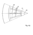
- Figure 1d leaves a partial sectional view in the region of the annular channel A1 for a modification of the embodiment FIGS. 1a ) and 1b ) detect.
- a plurality of channels A1 are arranged distributed over the circumference of the pressure chamber driver 1 and delimited from each other by radially extending boundary walls 17.
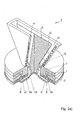
- FIGS. 2a ) and 2 B show a perspective view and a cross-sectional view of a second embodiment of a compression driver 1.
- the channels A1 are funnel-shaped expanded from the compression chamber 8 to the plenum 11.
- the housing bottom 3 opposite and the channel A1 above limiting housing wall 17 is inclined.
- the compression chamber 8 V-shaped by inclined walls designed and adapted to the V-shaped membrane 9. Down to the housing bottom 3 leading openings connect the compression chamber 8 and the associated radially extending channel A1.
- the further design of the sound guide body 13 and the sound wave guide element 14 is carried out comparable to the first embodiment, so that reference can be made to what is said there.
- channels A1 may be circumferentially formed throughout as an integral channel. Also conceivable is the in Figure 2c ) outlined alternative embodiment with a plurality of separated by partitions channels.
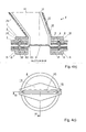
- FIGS. 3a ) and 3b ) show a third embodiment of a ring diaphragm compression driver 1 in perspective and in cross-sectional view.
- the central sound guide body 13 in the region of the annular collecting space 11 with over the length in the collecting space from the housing bottom 3 to the beginning of sound inlet 16 of the sound outlet channel 12 with a constant diameter, ie executed with a constant cross-section.
- the third embodiment outlines a version of the annular diaphragm compression driver 1 with two superimposed annular magnet system units 4, each with an annular membrane 9 introduced into an annular compression chamber 8. This increases the sound pressure.
- both membranes 9 the diameter of both membranes 9 is identical.
- the frequency characteristics of both magnetic system units 4 with associated membranes 9 is almost identical.
- the channels A3 and B3 of the upper and lower magnetic system unit 4 are identical in contour and length to each other, but mirrored, so that the sound paths of the two magnetic system units 4 are comparable to each other.
- the sound emerging from the channels A3 and B3 is then collected in the collecting space 11 and deflected upwards in the direction of the sound outlet channel 12.
- the sound wave is then converted by the rotationally symmetrical annular wavefront into a wave front adapted to the slot-shaped sound exit of the open sound exit end 15.
- contour of the collecting space 11 and of the sound discharge channel 12 closing thereon is then adapted to the specific design of the annular diaphragm compression driver 1 such that a desired planar, concave or convex wavefront is achieved at the sound exit end 15.
- angles .alpha. And .beta For the inclination of the sound guide body on the mutually opposite sides, the possibility which can likewise be used for all previously and subsequently described embodiments is sketched to set the vertical dispersion. If the angles ⁇ and ⁇ are equal, then the vertical dispersion is 0 °. A decreasing angle ⁇ , such that ⁇ ⁇ , leads to an increase in the vertical dispersion, i. H. a convex angle of radiation at the slot exit.
- Figure 3c reveals a plan view of the third embodiment of the annular diaphragm compression driver 1. It is again clear that a transition from a circular or oval rotationally symmetrical cross section takes place in an adapted to the slot-shaped sound outlet end 15 line-shaped cross section through the contour of the sound guide body 13 and the sound wave sliding element.
- channels A3 of the upper magnet system unit 2 are placed next to one another alternately with the channels B3 of the lower magnet system unit, so that the channels A3, B3 of the upper and lower magnet system unit 4 alternate.
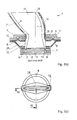
- FIGS. 4a ) and 4b ) can be seen a perspective view and a cross-sectional view of a fourth embodiment of a ring diaphragm compression driver 1, in which again two magnetic system units 4 are arranged with respective associated annular membranes 9 one above the other.
- annular compression chambers 8 of the upper and lower magnet system unit 4 are connected via openings 18 with a common channel A, which leads radially from the height of the compression chamber 8 inwardly to the collecting space 11.
- This may in turn be a single circumferential (360 °) channel A or a plurality of juxtaposed and spaced by partitions channels.
- the collecting space 11 is again delimited on the inside by the central sound guide body 13 extending from the housing bottom 3.
- This sound guide body 13 has over the length in the collecting chamber 11 a constant diameter.
- FIGS. 5a ) and 5b ) show a fifth embodiment of a ring-shaped compression driver 1.
- the sound guide body 13 formed in the region of the collecting space 11 in the direction of sound inlet beginning 16 partially tapered.
- annular magnet system units 4 are arranged one above the other, wherein the upper magnet system unit has a larger diameter than the lower magnet system unit.
- the upper annular membrane 9 is larger than the lower membrane 9.
- the basic design of the magnet system unit 4 is comparable to the previously described embodiments, so that reference can be made to the statements made there.
- the compression chamber 8 of the upper magnet system unit 4 is connected via channels A5 to the collecting space 11 which is bounded by the outer wall of the sound guiding body 13 and by walls of the magnet system unit 4.
- the compression chamber 8 of the lower magnet system unit 4 is open at the top and opens directly into the collecting space 11.
- the conically tapering sound guide body 13 With the help of the conically tapering sound guide body 13 in the region of the collecting space 11 and the inclined and upward in the direction of sound inlet beginning 16 partially tapered annular plenum 11, the sound paths of the different diameter of the membrane 9 different frequency ranges are coordinated so that a phase-correct annular wavefront arises.
- This wavefront matched with respect to the phase position is then transferred in the sound exit channel 12 from the rotationally symmetrical cross section into the slot-shaped cross section with the aid of a corresponding, previously described contour of the sound guide body 13 over at least part of the length of the sound wave guide element 14.
- FIG. 5b reveals an embodiment of the sound wave guide element 14 with the sound guide body 13, which can in principle also be used in conjunction with the previously described compression drivers.
- the circumferential walls of the sound waveguide 14 and corresponding to the outer walls of the sound waveguide 14 are curved with a radius a and b of the opposite walls of the sound waveguide executed. If the radius a is equal to the radius b, the sound wave at the sound outlet end 15 is flat, d. H. the dispersion angle is 0 °. A radius a greater b leads to a concave wavefront at the sound exit end and a radius a smaller b to a convex wavefront or a rising vertical angle.
- FIG. 5d shows a partial sectional view through the channels A5. These are in turn delimited from each other by intermediate walls 17, so that a plurality of separate, radially extending channels A5 are arranged distributed over the circumference.
- FIGS. 6a) to 6d disclose a sixth embodiment of a ring diaphragm compression driver 1.
- two magnet system units 4 are arranged one above the other, each with built-in annular membranes 9.
- a respective annular diaphragm 9 is movably received in a respective compression chamber 8 in the manner described above.
- the upper annular diaphragm 9 has a larger diameter than the lower diaphragm 9.
- the magnet system units may be implemented as separate housing parts which are bolted or welded together. It is clear that the channels A6 of the upper magnet system unit 4 are arranged from the upper compression chamber 8 to the collecting space 11 above the lower channels C6 of the lower compression chamber 8 of the lower magnet system unit 4. The merging, mixing and running time adjustment of the upper and lower magnet system unit generated sound waves is made in the plenum 11.
- the diameter of the collecting chamber 11 bounding sound guide body 13 is partially constant. Following this constant section, the diameter of the sound guide body 13 is tapered to a region at which the rotationally symmetrical cross section of the conically tapering section of the sound guide body 13 is transferred to a cross section adapted to the slot-shaped cross section (eg linear).
- FIG. 6d shows a sectional view in the region of the channels A6 and C6 of the upper and lower magnet system unit 4.
- the channels A6 and C6 are in turn separated from each other by intermediate walls 17. They extend radially from the respective outer compression chamber 8 to the internal collecting space 11.
- the upper channels A6 and lower channels C6 are arranged one above the other. In this way, it is possible to provide a higher number of channels A6 and C6. This has the advantage that a larger volume of air can be transported.
- the lower channels C6 of the lower, smaller diameter magnet system unit 4 have a lower ready than the upper channels A6 of the upper, larger diameter magnet system unit 4.
- the lower magnet system unit 4 is designed for higher frequencies than the upper, larger diameter magnet system unit 4.
- the length, width and contour of the channels are adapted to these frequency ranges.
- FIGS. 7a) to 7d show a seventh embodiment of the annular diaphragm compression driver 1, wherein in principle the third embodiment with two superposed magnetic system units 4 with the sixth Embodiment is combined with an underlying further magnet system unit of smaller diameter.
- the cross section of the collecting space is initially tapered and then constant from the lower region adjacent to the lower compression chamber of the third magnet system unit 4 in the lower region.
- the upper end of the collecting chamber 11 with a constant cross-section then passes into the sound outlet channel 12, in which then an adjustment of the annular, preferably rotationally symmetrical cross-section takes place at the slot-shaped cross section in the manner described above.
- the annular wavefront at the upper outlet of the collecting space 11 is then adapted to the slot-shaped outlet end with the aid of the contour of the sound outlet channel 12.
- FIG. 7c again leaves a top view of the pressure chamber driver FIGS. 7a ) and 7b ) detect. It is clear in the manner already described in detail above that the annular, for example, oval, round, elliptical or polygonal or otherwise rotationally symmetrical contour is transferred at the beginning of the sound entrance into a slot-shaped contour at the sound outlet end 15.
- FIG. 7d omits a cross-sectional view of the seventh embodiment of the pressure chamber driver 1 FIGS. 7a) to 7c ) detect.
Landscapes
- Health & Medical Sciences (AREA)
- Otolaryngology (AREA)
- Physics & Mathematics (AREA)
- Engineering & Computer Science (AREA)
- Acoustics & Sound (AREA)
- Signal Processing (AREA)
- Audible-Bandwidth Dynamoelectric Transducers Other Than Pickups (AREA)
- Reciprocating Pumps (AREA)
Applications Claiming Priority (1)
| Application Number | Priority Date | Filing Date | Title |
|---|---|---|---|
| DE102012102207A DE102012102207B3 (de) | 2012-03-15 | 2012-03-15 | Ringmembran-Kompressionstreiber |
Publications (3)
| Publication Number | Publication Date |
|---|---|
| EP2640089A2 true EP2640089A2 (fr) | 2013-09-18 |
| EP2640089A3 EP2640089A3 (fr) | 2015-09-30 |
| EP2640089B1 EP2640089B1 (fr) | 2017-10-11 |
Family
ID=47845820
Family Applications (1)
| Application Number | Title | Priority Date | Filing Date |
|---|---|---|---|
| EP13158627.3A Active EP2640089B1 (fr) | 2012-03-15 | 2013-03-11 | Actuateur à compression avec membrane annulaire |
Country Status (4)
| Country | Link |
|---|---|
| US (1) | US9008343B2 (fr) |
| EP (1) | EP2640089B1 (fr) |
| CN (1) | CN103369438B (fr) |
| DE (1) | DE102012102207B3 (fr) |
Cited By (8)
| Publication number | Priority date | Publication date | Assignee | Title |
|---|---|---|---|---|
| WO2018038825A1 (fr) * | 2016-08-22 | 2018-03-01 | Harman International Industries, Incorporated | Circuit d'attaque de compression et ensemble prise de phasage pour celui-ci |
| US10271131B2 (en) | 2014-10-08 | 2019-04-23 | Harman International Industries, Incorporated | Shallow profile compression driver |
| US10327068B2 (en) | 2017-11-16 | 2019-06-18 | Harman International Industries, Incorporated | Compression driver with side-firing compression chamber |
| EP3644623A1 (fr) | 2018-10-26 | 2020-04-29 | B&C Speakers S.P.A. | Pilote coaxial a compression |
| CN111800681A (zh) * | 2020-06-30 | 2020-10-20 | 深圳易科声光科技股份有限公司 | 声音压缩导向装置 |
| US11336993B2 (en) | 2019-12-19 | 2022-05-17 | B & C Speakers S.P.A. | Compression driver |
| WO2024153833A1 (fr) | 2023-01-18 | 2024-07-25 | Estudio De Asesoramiento Jofarma, S.L.U. | Transducteur de compression électrodynamique à canaux de pression variable |
| US12156006B2 (en) | 2022-05-09 | 2024-11-26 | B&C Speakers S.P.A | Acoustic compression chamber with modally coupled annular diaphragm |
Families Citing this family (10)
| Publication number | Priority date | Publication date | Assignee | Title |
|---|---|---|---|---|
| EP3335433B1 (fr) | 2015-08-14 | 2023-05-31 | Dolby Laboratories Licensing Corporation | Haut-parleur émettant vers le haut vec dispersion asymétrique pour générer des ondes sonores réfléchies |
| US10531200B2 (en) | 2015-10-23 | 2020-01-07 | Harman International Industries, Incorporated | Dual asymmetric compression driver |
| USD814441S1 (en) * | 2016-05-16 | 2018-04-03 | Scott Hanna | Loudspeaker horn |
| US20180063635A1 (en) | 2016-09-01 | 2018-03-01 | Audeze, Llc | Non-axisymmetric and non-horn phase plugs |
| US10250972B2 (en) * | 2017-03-23 | 2019-04-02 | Apple Inc. | Phase plug having non-round face profile |
| WO2020061304A1 (fr) * | 2018-09-19 | 2020-03-26 | Polk Audio, Llc | Transducteur audio doté d'une ventilation forcée de moteur et procédé |
| US11877120B2 (en) * | 2022-06-13 | 2024-01-16 | Harman International Industries, Incorporated | Compression driver having rectangular exit |
| US20250234134A1 (en) * | 2024-01-16 | 2025-07-17 | Harman Professional, Inc. | Dual compression driver with single magnet |
| US20260101138A1 (en) * | 2024-09-30 | 2026-04-09 | Harman Professional, Inc. | Dual compression driver with rectangular exit |
| WO2026080064A1 (fr) * | 2024-10-08 | 2026-04-16 | Harman Professional, Inc. | Moteur de compression à membrane unique à configuration inversée |
Citations (5)
| Publication number | Priority date | Publication date | Assignee | Title |
|---|---|---|---|---|
| US4325456A (en) | 1980-10-10 | 1982-04-20 | Altec Corporation | Acoustical transformer for compression-type loudspeaker with an annular diaphragm |
| EP0793216A2 (fr) | 1996-02-29 | 1997-09-03 | Svetlomir Alexandrov | Actionneur pour chambre de compression |
| DE19626236C2 (de) | 1996-02-29 | 1998-01-22 | Svetlomir Alexandrov | Druckkammertreiber |
| US20110085692A1 (en) | 2008-06-11 | 2011-04-14 | Harman International Industries, Incorporated | Dual compression drivers and phasing plugs for compression drivers |
| US20120033841A1 (en) | 2010-08-04 | 2012-02-09 | Robert Bosch Gmbh | Annular ring acoustic transformer |
Family Cites Families (10)
| Publication number | Priority date | Publication date | Assignee | Title |
|---|---|---|---|---|
| US4091891A (en) * | 1973-01-17 | 1978-05-30 | Onkyo Kabushiki Kaisha | Horn speaker |
| FR2627886B1 (fr) * | 1988-02-29 | 1994-05-13 | Heil Christian | Guide d'onde sonore cylindrique |
| GB2270606B (en) * | 1992-09-15 | 1996-03-20 | Anthony John Andrews | Loudspeaker enclosure |
| FR2735646B1 (fr) * | 1995-06-16 | 1997-08-22 | Phl Audio | Haut-parleur pour frequences elevees |
| US6320970B1 (en) * | 1998-09-25 | 2001-11-20 | Eugene J. Czerwinski | High frequency compression drivers |
| US8718310B2 (en) * | 2001-10-19 | 2014-05-06 | Qsc Holdings, Inc. | Multiple aperture speaker assembly |
| US8036408B2 (en) * | 2005-12-22 | 2011-10-11 | Harman International Industries, Incorporated | Phasing plug for a compression driver |
| US7802650B2 (en) * | 2008-07-09 | 2010-09-28 | John Kevin Bartlett | Combination midrange and high frequency horn |
| ES2574847T3 (es) * | 2008-07-24 | 2016-06-22 | Genelec Oy | Unidad de transductor de altavoz combinado insertado |
| US8139804B2 (en) * | 2009-06-24 | 2012-03-20 | Bose Corporation | Electroacoustic transducing with a bridge phase plug |
-
2012
- 2012-03-15 DE DE102012102207A patent/DE102012102207B3/de not_active Expired - Fee Related
-
2013
- 2013-03-11 EP EP13158627.3A patent/EP2640089B1/fr active Active
- 2013-03-13 US US13/799,453 patent/US9008343B2/en active Active
- 2013-03-15 CN CN201310221842.5A patent/CN103369438B/zh active Active
Patent Citations (5)
| Publication number | Priority date | Publication date | Assignee | Title |
|---|---|---|---|---|
| US4325456A (en) | 1980-10-10 | 1982-04-20 | Altec Corporation | Acoustical transformer for compression-type loudspeaker with an annular diaphragm |
| EP0793216A2 (fr) | 1996-02-29 | 1997-09-03 | Svetlomir Alexandrov | Actionneur pour chambre de compression |
| DE19626236C2 (de) | 1996-02-29 | 1998-01-22 | Svetlomir Alexandrov | Druckkammertreiber |
| US20110085692A1 (en) | 2008-06-11 | 2011-04-14 | Harman International Industries, Incorporated | Dual compression drivers and phasing plugs for compression drivers |
| US20120033841A1 (en) | 2010-08-04 | 2012-02-09 | Robert Bosch Gmbh | Annular ring acoustic transformer |
Non-Patent Citations (1)
| Title |
|---|
| A. VOISHVILLO: "Dual Diaphragm Compression drivers", AUDIO ENGINEERING SOCIETY CONVENTION PAPER, 131 ST CONVENTION, 20 October 2011 (2011-10-20) |
Cited By (11)
| Publication number | Priority date | Publication date | Assignee | Title |
|---|---|---|---|---|
| US10271131B2 (en) | 2014-10-08 | 2019-04-23 | Harman International Industries, Incorporated | Shallow profile compression driver |
| US10531184B2 (en) | 2014-10-08 | 2020-01-07 | Harman International Industries, Incorporated | Shallow profile compression driver |
| WO2018038825A1 (fr) * | 2016-08-22 | 2018-03-01 | Harman International Industries, Incorporated | Circuit d'attaque de compression et ensemble prise de phasage pour celui-ci |
| US10038954B2 (en) | 2016-08-22 | 2018-07-31 | Harman International Industries, Incorporated | Compression driver and phasing plug assembly therefor |
| US10327068B2 (en) | 2017-11-16 | 2019-06-18 | Harman International Industries, Incorporated | Compression driver with side-firing compression chamber |
| EP3644623A1 (fr) | 2018-10-26 | 2020-04-29 | B&C Speakers S.P.A. | Pilote coaxial a compression |
| US11343608B2 (en) | 2018-10-26 | 2022-05-24 | B&C Speakers S.P.A. | Coaxial compression driver |
| US11336993B2 (en) | 2019-12-19 | 2022-05-17 | B & C Speakers S.P.A. | Compression driver |
| CN111800681A (zh) * | 2020-06-30 | 2020-10-20 | 深圳易科声光科技股份有限公司 | 声音压缩导向装置 |
| US12156006B2 (en) | 2022-05-09 | 2024-11-26 | B&C Speakers S.P.A | Acoustic compression chamber with modally coupled annular diaphragm |
| WO2024153833A1 (fr) | 2023-01-18 | 2024-07-25 | Estudio De Asesoramiento Jofarma, S.L.U. | Transducteur de compression électrodynamique à canaux de pression variable |
Also Published As
| Publication number | Publication date |
|---|---|
| CN103369438A (zh) | 2013-10-23 |
| EP2640089B1 (fr) | 2017-10-11 |
| US9008343B2 (en) | 2015-04-14 |
| CN103369438B (zh) | 2018-02-27 |
| DE102012102207B3 (de) | 2013-08-29 |
| US20130243232A1 (en) | 2013-09-19 |
| EP2640089A3 (fr) | 2015-09-30 |
Similar Documents
| Publication | Publication Date | Title |
|---|---|---|
| EP2640089B1 (fr) | Actuateur à compression avec membrane annulaire | |
| DE19843323C2 (de) | Phasenstecker für einen Lautsprecher und Lautsprecher | |
| DE4092322C2 (de) | Trichterlautsprecher und zugehöriger Schalltrichter | |
| DE68915582T2 (de) | Zylindrischer Akustischer Wellenleiter. | |
| DE102008010524B4 (de) | Lautsprecherbox mit variabler Abstrahlcharakteristik | |
| DE102009051237A1 (de) | Akustisches Mehrfachblendenhorn | |
| DE2401132C3 (de) | Vorrichtung zur gerichteten Abstrahlung von Schallwellen | |
| DE2648428A1 (de) | Akustischer transformator fuer trichterlautsprecher | |
| EP0755045A2 (fr) | Dispositif de suppression d'ondes sonores | |
| EP3189674B1 (fr) | Mems haut-parleur comprenant un génerateur de son et un amplificateur de son | |
| EP0793216B1 (fr) | Actionneur pour chambre de compression | |
| DE102016208344A1 (de) | Fluidisches Bauteil | |
| DE102012107645B4 (de) | Akustischer wandler | |
| DE2401925B2 (de) | Trichterlautsprecher | |
| DE102005051809B3 (de) | Akustischer Transformer | |
| DE10322692B4 (de) | Membran für elektroakustische Wandler, elektroakustischer Wandler und Lautsprecher | |
| DE69913214T2 (de) | Kombinationspfeife | |
| DE69917148T2 (de) | Elektroakustischer wandler und membrane für elektroakustischen wandler | |
| DE6605298U (de) | Signalhorn mit verstellbaren tonfrequenzen fuer vorzugsweise kraftfahrzeuge | |
| DE102012111612A1 (de) | Akustischer Hochfrequenzfokussierer | |
| DE3923189C2 (fr) | ||
| DE102008057315A1 (de) | Lautsprecheranordnung | |
| DE69736541T2 (de) | Hörhilfegerät | |
| DE3002843C2 (fr) | ||
| DE2637412A1 (de) | Elektromagnetischer wandler |
Legal Events
| Date | Code | Title | Description |
|---|---|---|---|
| PUAI | Public reference made under article 153(3) epc to a published international application that has entered the european phase |
Free format text: ORIGINAL CODE: 0009012 |
|
| AK | Designated contracting states |
Kind code of ref document: A2 Designated state(s): AL AT BE BG CH CY CZ DE DK EE ES FI FR GB GR HR HU IE IS IT LI LT LU LV MC MK MT NL NO PL PT RO RS SE SI SK SM TR |
|
| AX | Request for extension of the european patent |
Extension state: BA ME |
|
| PUAL | Search report despatched |
Free format text: ORIGINAL CODE: 0009013 |
|
| AK | Designated contracting states |
Kind code of ref document: A3 Designated state(s): AL AT BE BG CH CY CZ DE DK EE ES FI FR GB GR HR HU IE IS IT LI LT LU LV MC MK MT NL NO PL PT RO RS SE SI SK SM TR |
|
| AX | Request for extension of the european patent |
Extension state: BA ME |
|
| RIC1 | Information provided on ipc code assigned before grant |
Ipc: H04R 1/32 20060101AFI20150824BHEP Ipc: H04R 9/02 20060101ALI20150824BHEP Ipc: H04R 1/30 20060101ALN20150824BHEP |
|
| 17P | Request for examination filed |
Effective date: 20160323 |
|
| RBV | Designated contracting states (corrected) |
Designated state(s): AL AT BE BG CH CY CZ DE DK EE ES FI FR GB GR HR HU IE IS IT LI LT LU LV MC MK MT NL NO PL PT RO RS SE SI SK SM TR |
|
| RIC1 | Information provided on ipc code assigned before grant |
Ipc: H04R 9/02 20060101ALI20170222BHEP Ipc: H04R 1/30 20060101ALN20170222BHEP Ipc: H04R 1/32 20060101AFI20170222BHEP |
|
| RIC1 | Information provided on ipc code assigned before grant |
Ipc: H04R 1/32 20060101AFI20170308BHEP Ipc: H04R 9/02 20060101ALI20170308BHEP Ipc: H04R 1/30 20060101ALN20170308BHEP |
|
| GRAP | Despatch of communication of intention to grant a patent |
Free format text: ORIGINAL CODE: EPIDOSNIGR1 |
|
| RIC1 | Information provided on ipc code assigned before grant |
Ipc: H04R 1/30 20060101ALN20170419BHEP Ipc: H04R 1/32 20060101AFI20170419BHEP Ipc: H04R 9/02 20060101ALI20170419BHEP |
|
| INTG | Intention to grant announced |
Effective date: 20170503 |
|
| GRAS | Grant fee paid |
Free format text: ORIGINAL CODE: EPIDOSNIGR3 |
|
| GRAA | (expected) grant |
Free format text: ORIGINAL CODE: 0009210 |
|
| AK | Designated contracting states |
Kind code of ref document: B1 Designated state(s): AL AT BE BG CH CY CZ DE DK EE ES FI FR GB GR HR HU IE IS IT LI LT LU LV MC MK MT NL NO PL PT RO RS SE SI SK SM TR |
|
| REG | Reference to a national code |
Ref country code: GB Ref legal event code: FG4D Free format text: NOT ENGLISH |
|
| REG | Reference to a national code |
Ref country code: CH Ref legal event code: EP |
|
| REG | Reference to a national code |
Ref country code: IE Ref legal event code: FG4D Free format text: LANGUAGE OF EP DOCUMENT: GERMAN |
|
| REG | Reference to a national code |
Ref country code: AT Ref legal event code: REF Ref document number: 936997 Country of ref document: AT Kind code of ref document: T Effective date: 20171115 |
|
| REG | Reference to a national code |
Ref country code: DE Ref legal event code: R096 Ref document number: 502013008530 Country of ref document: DE |
|
| REG | Reference to a national code |
Ref country code: NL Ref legal event code: MP Effective date: 20171011 |
|
| REG | Reference to a national code |
Ref country code: LT Ref legal event code: MG4D |
|
| REG | Reference to a national code |
Ref country code: FR Ref legal event code: PLFP Year of fee payment: 6 |
|
| PG25 | Lapsed in a contracting state [announced via postgrant information from national office to epo] |
Ref country code: NL Free format text: LAPSE BECAUSE OF FAILURE TO SUBMIT A TRANSLATION OF THE DESCRIPTION OR TO PAY THE FEE WITHIN THE PRESCRIBED TIME-LIMIT Effective date: 20171011 |
|
| PG25 | Lapsed in a contracting state [announced via postgrant information from national office to epo] |
Ref country code: NO Free format text: LAPSE BECAUSE OF FAILURE TO SUBMIT A TRANSLATION OF THE DESCRIPTION OR TO PAY THE FEE WITHIN THE PRESCRIBED TIME-LIMIT Effective date: 20180111 Ref country code: ES Free format text: LAPSE BECAUSE OF FAILURE TO SUBMIT A TRANSLATION OF THE DESCRIPTION OR TO PAY THE FEE WITHIN THE PRESCRIBED TIME-LIMIT Effective date: 20171011 Ref country code: LT Free format text: LAPSE BECAUSE OF FAILURE TO SUBMIT A TRANSLATION OF THE DESCRIPTION OR TO PAY THE FEE WITHIN THE PRESCRIBED TIME-LIMIT Effective date: 20171011 Ref country code: SE Free format text: LAPSE BECAUSE OF FAILURE TO SUBMIT A TRANSLATION OF THE DESCRIPTION OR TO PAY THE FEE WITHIN THE PRESCRIBED TIME-LIMIT Effective date: 20171011 Ref country code: FI Free format text: LAPSE BECAUSE OF FAILURE TO SUBMIT A TRANSLATION OF THE DESCRIPTION OR TO PAY THE FEE WITHIN THE PRESCRIBED TIME-LIMIT Effective date: 20171011 |
|
| PG25 | Lapsed in a contracting state [announced via postgrant information from national office to epo] |
Ref country code: HR Free format text: LAPSE BECAUSE OF FAILURE TO SUBMIT A TRANSLATION OF THE DESCRIPTION OR TO PAY THE FEE WITHIN THE PRESCRIBED TIME-LIMIT Effective date: 20171011 Ref country code: LV Free format text: LAPSE BECAUSE OF FAILURE TO SUBMIT A TRANSLATION OF THE DESCRIPTION OR TO PAY THE FEE WITHIN THE PRESCRIBED TIME-LIMIT Effective date: 20171011 Ref country code: BG Free format text: LAPSE BECAUSE OF FAILURE TO SUBMIT A TRANSLATION OF THE DESCRIPTION OR TO PAY THE FEE WITHIN THE PRESCRIBED TIME-LIMIT Effective date: 20180111 Ref country code: IS Free format text: LAPSE BECAUSE OF FAILURE TO SUBMIT A TRANSLATION OF THE DESCRIPTION OR TO PAY THE FEE WITHIN THE PRESCRIBED TIME-LIMIT Effective date: 20180211 Ref country code: RS Free format text: LAPSE BECAUSE OF FAILURE TO SUBMIT A TRANSLATION OF THE DESCRIPTION OR TO PAY THE FEE WITHIN THE PRESCRIBED TIME-LIMIT Effective date: 20171011 Ref country code: GR Free format text: LAPSE BECAUSE OF FAILURE TO SUBMIT A TRANSLATION OF THE DESCRIPTION OR TO PAY THE FEE WITHIN THE PRESCRIBED TIME-LIMIT Effective date: 20180112 |
|
| REG | Reference to a national code |
Ref country code: DE Ref legal event code: R097 Ref document number: 502013008530 Country of ref document: DE |
|
| PG25 | Lapsed in a contracting state [announced via postgrant information from national office to epo] |
Ref country code: DK Free format text: LAPSE BECAUSE OF FAILURE TO SUBMIT A TRANSLATION OF THE DESCRIPTION OR TO PAY THE FEE WITHIN THE PRESCRIBED TIME-LIMIT Effective date: 20171011 Ref country code: EE Free format text: LAPSE BECAUSE OF FAILURE TO SUBMIT A TRANSLATION OF THE DESCRIPTION OR TO PAY THE FEE WITHIN THE PRESCRIBED TIME-LIMIT Effective date: 20171011 Ref country code: SK Free format text: LAPSE BECAUSE OF FAILURE TO SUBMIT A TRANSLATION OF THE DESCRIPTION OR TO PAY THE FEE WITHIN THE PRESCRIBED TIME-LIMIT Effective date: 20171011 Ref country code: CZ Free format text: LAPSE BECAUSE OF FAILURE TO SUBMIT A TRANSLATION OF THE DESCRIPTION OR TO PAY THE FEE WITHIN THE PRESCRIBED TIME-LIMIT Effective date: 20171011 |
|
| PLBE | No opposition filed within time limit |
Free format text: ORIGINAL CODE: 0009261 |
|
| STAA | Information on the status of an ep patent application or granted ep patent |
Free format text: STATUS: NO OPPOSITION FILED WITHIN TIME LIMIT |
|
| PG25 | Lapsed in a contracting state [announced via postgrant information from national office to epo] |
Ref country code: SM Free format text: LAPSE BECAUSE OF FAILURE TO SUBMIT A TRANSLATION OF THE DESCRIPTION OR TO PAY THE FEE WITHIN THE PRESCRIBED TIME-LIMIT Effective date: 20171011 Ref country code: PL Free format text: LAPSE BECAUSE OF FAILURE TO SUBMIT A TRANSLATION OF THE DESCRIPTION OR TO PAY THE FEE WITHIN THE PRESCRIBED TIME-LIMIT Effective date: 20171011 Ref country code: IT Free format text: LAPSE BECAUSE OF FAILURE TO SUBMIT A TRANSLATION OF THE DESCRIPTION OR TO PAY THE FEE WITHIN THE PRESCRIBED TIME-LIMIT Effective date: 20171011 Ref country code: RO Free format text: LAPSE BECAUSE OF FAILURE TO SUBMIT A TRANSLATION OF THE DESCRIPTION OR TO PAY THE FEE WITHIN THE PRESCRIBED TIME-LIMIT Effective date: 20171011 |
|
| 26N | No opposition filed |
Effective date: 20180712 |
|
| PG25 | Lapsed in a contracting state [announced via postgrant information from national office to epo] |
Ref country code: MT Free format text: LAPSE BECAUSE OF FAILURE TO SUBMIT A TRANSLATION OF THE DESCRIPTION OR TO PAY THE FEE WITHIN THE PRESCRIBED TIME-LIMIT Effective date: 20171011 |
|
| REG | Reference to a national code |
Ref country code: CH Ref legal event code: PL |
|
| PG25 | Lapsed in a contracting state [announced via postgrant information from national office to epo] |
Ref country code: SI Free format text: LAPSE BECAUSE OF FAILURE TO SUBMIT A TRANSLATION OF THE DESCRIPTION OR TO PAY THE FEE WITHIN THE PRESCRIBED TIME-LIMIT Effective date: 20171011 Ref country code: MC Free format text: LAPSE BECAUSE OF FAILURE TO SUBMIT A TRANSLATION OF THE DESCRIPTION OR TO PAY THE FEE WITHIN THE PRESCRIBED TIME-LIMIT Effective date: 20171011 |
|
| REG | Reference to a national code |
Ref country code: BE Ref legal event code: MM Effective date: 20180331 |
|
| REG | Reference to a national code |
Ref country code: IE Ref legal event code: MM4A |
|
| PG25 | Lapsed in a contracting state [announced via postgrant information from national office to epo] |
Ref country code: LU Free format text: LAPSE BECAUSE OF NON-PAYMENT OF DUE FEES Effective date: 20180311 |
|
| PG25 | Lapsed in a contracting state [announced via postgrant information from national office to epo] |
Ref country code: IE Free format text: LAPSE BECAUSE OF NON-PAYMENT OF DUE FEES Effective date: 20180311 |
|
| PG25 | Lapsed in a contracting state [announced via postgrant information from national office to epo] |
Ref country code: BE Free format text: LAPSE BECAUSE OF NON-PAYMENT OF DUE FEES Effective date: 20180331 Ref country code: LI Free format text: LAPSE BECAUSE OF NON-PAYMENT OF DUE FEES Effective date: 20180331 Ref country code: CH Free format text: LAPSE BECAUSE OF NON-PAYMENT OF DUE FEES Effective date: 20180331 |
|
| REG | Reference to a national code |
Ref country code: AT Ref legal event code: MM01 Ref document number: 936997 Country of ref document: AT Kind code of ref document: T Effective date: 20180311 |
|
| PG25 | Lapsed in a contracting state [announced via postgrant information from national office to epo] |
Ref country code: AT Free format text: LAPSE BECAUSE OF NON-PAYMENT OF DUE FEES Effective date: 20180311 |
|
| PG25 | Lapsed in a contracting state [announced via postgrant information from national office to epo] |
Ref country code: TR Free format text: LAPSE BECAUSE OF FAILURE TO SUBMIT A TRANSLATION OF THE DESCRIPTION OR TO PAY THE FEE WITHIN THE PRESCRIBED TIME-LIMIT Effective date: 20171011 |
|
| PG25 | Lapsed in a contracting state [announced via postgrant information from national office to epo] |
Ref country code: HU Free format text: LAPSE BECAUSE OF FAILURE TO SUBMIT A TRANSLATION OF THE DESCRIPTION OR TO PAY THE FEE WITHIN THE PRESCRIBED TIME-LIMIT; INVALID AB INITIO Effective date: 20130311 Ref country code: PT Free format text: LAPSE BECAUSE OF FAILURE TO SUBMIT A TRANSLATION OF THE DESCRIPTION OR TO PAY THE FEE WITHIN THE PRESCRIBED TIME-LIMIT Effective date: 20171011 |
|
| PG25 | Lapsed in a contracting state [announced via postgrant information from national office to epo] |
Ref country code: CY Free format text: LAPSE BECAUSE OF FAILURE TO SUBMIT A TRANSLATION OF THE DESCRIPTION OR TO PAY THE FEE WITHIN THE PRESCRIBED TIME-LIMIT Effective date: 20171011 Ref country code: MK Free format text: LAPSE BECAUSE OF NON-PAYMENT OF DUE FEES Effective date: 20171011 |
|
| PG25 | Lapsed in a contracting state [announced via postgrant information from national office to epo] |
Ref country code: AL Free format text: LAPSE BECAUSE OF FAILURE TO SUBMIT A TRANSLATION OF THE DESCRIPTION OR TO PAY THE FEE WITHIN THE PRESCRIBED TIME-LIMIT Effective date: 20171011 |
|
| REG | Reference to a national code |
Ref country code: DE Ref legal event code: R082 Ref document number: 502013008530 Country of ref document: DE Representative=s name: MEISSNER BOLTE PATENTANWAELTE RECHTSANWAELTE P, DE |
|
| P01 | Opt-out of the competence of the unified patent court (upc) registered |
Effective date: 20230517 |
|
| PGFP | Annual fee paid to national office [announced via postgrant information from national office to epo] |
Ref country code: GB Payment date: 20260324 Year of fee payment: 14 |
|
| PGFP | Annual fee paid to national office [announced via postgrant information from national office to epo] |
Ref country code: DE Payment date: 20260330 Year of fee payment: 14 |
|
| PGFP | Annual fee paid to national office [announced via postgrant information from national office to epo] |
Ref country code: FR Payment date: 20260324 Year of fee payment: 14 |