EP2640635B1 - Élévateur de fret compact pour avion commercial - Google Patents
Élévateur de fret compact pour avion commercial Download PDFInfo
- Publication number
- EP2640635B1 EP2640635B1 EP10784359.1A EP10784359A EP2640635B1 EP 2640635 B1 EP2640635 B1 EP 2640635B1 EP 10784359 A EP10784359 A EP 10784359A EP 2640635 B1 EP2640635 B1 EP 2640635B1
- Authority
- EP
- European Patent Office
- Prior art keywords
- lift platform
- deck
- lift
- aircraft
- opening
- Prior art date
- Legal status (The legal status is an assumption and is not a legal conclusion. Google has not performed a legal analysis and makes no representation as to the accuracy of the status listed.)
- Active
Links
Images







Classifications
-
- B—PERFORMING OPERATIONS; TRANSPORTING
- B64—AIRCRAFT; AVIATION; COSMONAUTICS
- B64D—EQUIPMENT FOR FITTING IN OR TO AIRCRAFT; FLIGHT SUITS; PARACHUTES; ARRANGEMENT OR MOUNTING OF POWER PLANTS OR PROPULSION TRANSMISSIONS IN AIRCRAFT
- B64D9/00—Equipment for handling freight; Equipment for facilitating passenger embarkation or the like
-
- B—PERFORMING OPERATIONS; TRANSPORTING
- B64—AIRCRAFT; AVIATION; COSMONAUTICS
- B64C—AEROPLANES; HELICOPTERS
- B64C1/00—Fuselages; Constructional features common to fuselages, wings, stabilising surfaces or the like
- B64C1/18—Floors
- B64C1/20—Floors specially adapted for freight
-
- Y—GENERAL TAGGING OF NEW TECHNOLOGICAL DEVELOPMENTS; GENERAL TAGGING OF CROSS-SECTIONAL TECHNOLOGIES SPANNING OVER SEVERAL SECTIONS OF THE IPC; TECHNICAL SUBJECTS COVERED BY FORMER USPC CROSS-REFERENCE ART COLLECTIONS [XRACs] AND DIGESTS
- Y02—TECHNOLOGIES OR APPLICATIONS FOR MITIGATION OR ADAPTATION AGAINST CLIMATE CHANGE
- Y02T—CLIMATE CHANGE MITIGATION TECHNOLOGIES RELATED TO TRANSPORTATION
- Y02T50/00—Aeronautics or air transport
- Y02T50/40—Weight reduction
Definitions
- the present invention relates generally to cargo lifts for aircraft, and, more particularly, to an internal cargo lift for raising/lowering cargo between decks of an aircraft that allows for convenient and rapid conversion of passenger seating areas or other previously unusable areas to cargo carriage space and back.
- a related problem is the difficulty in delivering the palletized cargo to the main (passenger) deck of the aircraft, even if this area is cleared of seating.
- cargo is ordinarily carried in palletized form in lower deck cargo compartments.
- ULDs unit load devices
- the ULDs may have a single line or "two abreast" configuration.
- next-day delivery and even same day delivery
- packages have increased the value of available cargo space. This is increasingly true in the case of regular passenger aircraft, due to the frequency of flights made to numerous destinations, as opposed to the hub-and-spoke operations to which classical daily/overnight freight operators have been wedded.
- an increased allowance for carry-on baggage has freed up lower deck cargo space and has allowed expanded cargo service on passenger aircraft.
- aircraft size i.e., the number of seats
- aircraft size must be matched to the economics of a particular route.
- a bigger aircraft, with a larger lower lobe capacity cannot be economically placed on a route if its seats are not also filled to an adequate extent.
- the ability to carry high-value extra cargo is still limited.
- the present invention has solved the problems cited above, and is an apparatus for transferring cargo between an upper deck and a lower deck of an aircraft.
- the apparatus comprises: (a) a lift platform that is receivable in a through opening formed in the upper deck of the aircraft, the lift platform having an upper surface for supporting a load of cargo thereon; (b) means for lowering and raising the lift platform between the upper deck and the lower deck so as to transfers loads of cargo to and from the upper deck via the through opening; and (c) means for selectively attaching edges of the lift platform to the upper deck in load-bearing engagement therewith when the lift platform is raised and stowed in the through opening, so that the lift platform shares structural loading of the upper deck during flight operation of the aircraft.
- the means for selectively attaching the edges of the lift platform to the upper deck in load-bearing engagement therewith may comprise means for selectively attaching first and second longitudinally extending side edges of the lift platform to first and second longitudinally extending side edges of the through opening, so that the lift platform shares structural loading of the upper deck in a lateral direction during flight operation of the aircraft.
- the means for selectively attaching the side edges of the lift platform to the side edges of the through opening may comprise at least one lock assembly on each of the side edges of the lift platform, each lock assembly comprising a first lock portion that is mounted to a longitudinal side edge of the lift platform, and a second lock portion that is mounted to a longitudinal side edge of the through opening for establishing load-bearing engagement with the first lock portion on the lift platform.
- the second lock portion may comprise a pin member that extends in a lateral direction from a side edge of the through opening, and the second lock portion may comprise a rotating latch that receives the pin member in lateral and vertical load-bearing engagement therewith.
- the side edges of the through opening may span a plurality of truncated lateral beams of the upper deck, and the lift platform may comprise a plurality of lateral beams that span a width of the lift platform and that are aligned axially with the truncated beams of the upper deck when the lift platform is raised and stowed in the through opening.
- the at least one lock assembly may comprise a plurality of the lock assemblies, each lock assembly being located at an axial juncture between one of the truncated beams of the upper deck and one of the lateral beams of the lift platform when the lift platform is raised and stowed in the through opening.
- the apparatus may comprise longitudinally extending header members that are mounted across the ends of the truncated beams of the upper deck and to intact lateral beams at forward and after ends of the through opening.
- the means for lowering and raising the lift platform may comprise a lift mechanism having at least one lift cable, and a drive assembly for selectively extending and retracting the lift cable so as to lower and raise the lift platform, substantially the entirety of the drive assembly being housed within the lift platform.
- the drive assembly may comprise: an anchor point for an end of the at least one lift cable; at least one ball screw and nut in cooperating drive engagement, the ball nut being located a spaced distance from the anchor point, at least one pulley mounted to the ball nut, the lift cable being routed over the pulley from the anchor point;, and a motor for reversibly rotating the ball screw, in a first direction that shortens the distance between the pulley and the anchor point so as to extend the cable from the lift platform, and in a second direction that increases the distance between the pulley and the anchor point so as to retract the cable into the lift platform.
- the at least one ball screw and nut may be mounted to extend generally horizontally within an interior height of the lift platform.
- the apparatus may further comprise means for stabilizing the lift platform as the lift platform is lowered and raised between the upper and lower decks of the aircraft.
- the means for stabilizing the lift platform may comprise first and second scissors-action stabilizer assemblies on longitudinally extending sides of the lift platform, each stabilizer assembly comprising at least one pair of rigid arm members joined in an X-shaped configuration by a central pivot point, first and second upper attachment points on the arm members that are pivotably mounted to the upper deck of the aircraft, and first and second lower attachment points on the arm members that are pivotably mounted to the longitudinally extending sides of the lift platform.
- the first and second attachment points on the arm members may each comprise a stationary pivot connection, and a sliding pivot connection that accommodates increases and decreases in distance between the first and second attachment points as the lift deck is raised and lowered.
- the sliding pivot connections may each comprise: at least one guide rail that extends in a substantially horizontal direction; a bracket member having at least one channel portion that receives the guide rail in sliding engagement therewith, so that the bracket member is free to slide horizontally while being supported vertically; and a pivot connection joining an end of one of the rigid leg members to the bracket member.
- the apparatus may further comprise first and second spaces formed intermediate the longitudinally extending side edges of the lift platform and longitudinally extending edges of the through opening, in which the rigid leg members of the stabilizing assembly nest when the lift platform is raised and stowed in the through opening.
- the apparatus may further comprise a recess in the lower deck of the aircraft for receiving the lift platform therein, so that the upper surface of the lift platform extends substantially flush with an upper surface of the lower deck when the lift platform is lowered therein.
- the recess in the lower deck of the aircraft may comprise an area of the lower deck of the aircraft in which upper edges of floor frames have been removed so as to form the recess therein.
- the apparatus may further comprise a translating floor assembly mounted in the area of the recess in the lower deck of the aircraft, the translating floor assembly having a first position which defines a floor surface that extends over the recess generally flush with the upper surface of the lower deck, and a second position which clears the recess for receiving the lift platform in the lower deck of the aircraft.
- the translating floor assembly may comprise a plurality of folding floor sections, each of the folding floor sections comprising: a laterally-extending frame that is received in an intercostal space intermediate the floor frames of the lower deck; at least one deck segment mounted to the frame for extending substantially flush with the upper surface of the lower deck when the frame is in a raised position; a plurality of folding leg members, each leg member having an upper end that is pivotably mounted to the frame and a lower end that is pivotably mounted to the lower deck in the intercostal space intermediate the floor frames; and means for selectively pivoting the leg members between a generally vertical orientation in which the frame is supported substantially flush with the surface of the lower deck, and a generally horizontal orientation in which the frame is dropped into the intercostal space so as to clear the recess to receive the lift platform in the lower deck.
- the means for selectively pivoting the leg members may comprise: at least one actuation link having an upper end that is mounted to an upper end of one of the folding leg members, and a lower end that is mounted to an actuation arm; a torque tube that is mounted to the actuation arm; and means for reversibly rotating the torque tube in a first direction such that the actuation link draws the leg member to the vertical orientation, and a second direction such that the actuation link lowers the leg member to the generally horizontal orientation.
- the present invention provides an apparatus for transferring cargo between an upper deck and a lower deck of an aircraft, comprising: (a) a through opening in the upper deck of the aircraft, the through opening comprising first and second longitudinally extending side edges formed across ends of a plurality of truncated lateral beams of the upper deck, and first and second longitudinal headers mounted across the ends of the truncated lateral beams and to intact lateral beams forward and aft of the through opening; (b) a lift platform that is receivable in the through opening in the upper deck, the lift platform comprising an upper surface for supporting a load of cargo thereon, and first and second longitudinally extending side edges that are positioned generally adjacent to the side edges of the through opening when the lift platform is in the raised position; (c) a drive assembly for selectively raising and lowering the lift platform between the upper deck and the lower deck so as to transfer loads of cargo to and from the upper deck via the through opening, the drive assembly comprising a motor and drive mechanism that are substantially
- the present invention also provides an aircraft having apparatus for transferring cargo between an upper deck and a lower deck thereof, the aircraft comprising: (a) a through opening formed in the upper deck; (b) a lift platform that is receivable in the through opening, the lift platform having an upper surface for supporting a load of cargo thereon; (c) means for lowering and raising the lift platform between the upper deck and the lower deck so as to transfers loads of cargo to and from the upper deck via the through opening; and (d) means for selectively attaching edges of the lift platform to the upper deck in load-bearing engagement therewith when the lift platform is raised and stowed in the through opening, so that the lift platform shares structural loading of the upper deck during flight operation of the aircraft.
- FIG. 1 shows an exemplary wide-body aircraft 10 having a lift assembly 12 installed therein, permitting the aircraft to carry cargo in ULDs 14 on both the cargo and main (passenger) decks 16, 18.
- the lift assembly is preferable installed in the aft portion of the aircraft, as shown in the figures.
- FIGS. 2-5 illustrate the basic operation of the system.
- the term “lower deck” refers to a first deck on which cargo is positioned
- the term “upper deck” refers to a second deck above the first, to and/or from which the cargo is transferred by the lift apparatus of the present invention.
- One may be a dedicated cargo deck and the other primarily a passenger deck, as shown in FIGS. 1-5 , or they may both be primarily cargo or passenger decks, particularly in the case of double-decked "jumbo" aircraft (e.g., a Boeing 747 or Airbus A380).
- FIG. 2 shows the aircraft in its ordinary, passenger-carrying configuration, with the interior of the upper lobe 24 devoted to seating 20 and overhead storage bins 22, and with carriage of ULDs 14 being confined to the lower lobe 26.
- the lift assembly 12 includes a lift platform 30 that is received within an opening in the main deck 18, so that when stowed its upper surface lies flush with the deck so that passenger seats 20 can be mounted thereon.
- the mechanism of the lift apparatus is essentially self-contained within the lift platform 28; no exterior devices encumber the interior of the aircraft when the apparatus is installed.
- the lift platform attaches structurally to the main deck 18 so as to form load-bearing component thereof, so that the structural impact to the aircraft (from its unmodified condition) is minimal.
- a cut-out 32 is formed in the floor of the cargo deck 16 to receive the platform when it is lowered, the cutout being spanned by removable tracks 34 when the lift platform is stowed in the raised position.
- a selected number of seats 20 are removed and a divider panel 36 is installed between the passenger and cargo areas of the upper deck. Owing to the limited vertical height of the ULDs, the overhead storage compartments can remain in place, greatly simplifying and expediting the conversion.
- the tracks 34 are removed so that the lift platform 30 can be lowered to position in which its upper surface is flush with that of the cargo deck 16, as shown in FIG. 3 . As the lift platform is lowered, a through opening 38 is vacated in the main deck 18.
- the ULDs are loaded/unloaded in the lower lobe through the main loading door (not shown) with which the aircraft was originally equipped.
- the ULDs/pallets are then moved longitudinally through the hold on tracks (not shown) on deck 16, which again are an original part of the aircraft.
- the upper surface of the lift platform 30 may be provided with corresponding track segments that align with those on the cargo deck when the lift is in the lowered position, so that the ULDs 14 can be transported thereover, e.g., to the position of the right-most ULD in FIG. 3 .
- ULDs can also be stopped atop the lift platform in the position shown in FIG. 3 , in preparation for being raised to the main passenger deck 18.
- the internal mechanism of the platform is actuated to raise/lower the ULD through the opening 38 in the main deck, in the manner shown in FIG. 4 .
- the platform reaches the raised position so that its upper surface is flush with that of the main deck 18, the pallet is moved off of the platform, in a forward direction towards the divider panel 36, or in a rearward direction towards the tail of the aircraft.
- the tracks remaining from the removed seats may be employed to support the ULDs for movement through the passenger cabin.
- the final pallet/ULD can remain in position atop the lift platform when the latter is locked in its raised position, as shown in FIG. 5 .
- the track segments 34 are then reinstalled over the floor cutout 32 and additional cargo containers are moved into place in the area below the raised lift platform 30; since the supports and drive mechanisms are self-contained, there are no obstructions below the platform that would interfere with passing/storing cargo containers thereunder. Unloading the aircraft using the cargo lift assembly is essentially the reverse of the loading process, lowering the ULDs from the passenger deck 18 and then passing them through the cargo hold and out the main loading door in a conventional manner.
- the lift assembly is preferably installed in the aft portion of the aircraft, but forward of the rear passenger door. Positioning the lift forward of the door avoids a "log jam" situation that could interfere with traffic flow, while rearwardly of the door the fuselage typically tapers in a manner that would impose impractical geometry and space restrictions. Furthermore, the barrier panel can be positioned as far forward as desired, without separating the passengers from the crew or from the main passenger-loading door at the front of the aircraft.
- the lifting and stabilizing mechanisms are all contained within the lift platform and the associated deck opening, very little modification of the aircraft is required to install the system.
- the main modification is to cut the through opening in the passenger deck 18; as is described in greater detail below, the lift deck is tied structurally to the main deck when in the stowed position, so that there is virtually no loss or compromise of structural integrity due to the opening 38.
- the receiver opening 32 in the lower deck does not affect structural integrity either, since the portion of the frames that is removed does not serve a structural purpose with respect to the aircraft body and is only provided to support the overlying floor surface.
- power requirements are met by simply connecting an electrical cable to the platform, to supply electrical power to the motor that is housed therein, and there is no need to add expensive and complicated hydraulics.
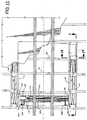
- FIGS. 6-7 show the relationship of the lift platform to the main and cargo decks in greater detail.
- the lift platform 30 nests closely within the opening 38 when in the raised position, with its upper surface lying flush with that of the passenger deck 18 as noted above.
- First and second track segments 42 align with corresponding tracks 44, (e.g., conventional seating tracks) on the surface of the passenger deck, and may be used for moving ULDs/cargo off and onto the lift platform 30.
- the through opening 38 in the deck itself is formed by cutting an area out of the floor and deck support beams 36, and then installing headers 48 that join the severed beam ends to the uncut beams at the forward and rearward ends of the opening.
- Locking mechanisms 50 are mounted at the inboard sides of the headers, at the location of each cut beam, for forming a structural engagement between the platform and the deck, as will be described in greater detail below.
- the lower opening 32 is formed by cutting down the upper edges of corresponding floor frames 52, to a height that generally matches that of the lift platform 30 so that the upper surface of the latter will be level with the floor of the cargo deck 18 when the platform is in the lowered position; as noted above, this does not compromise the structural integrity of the aircraft, since the upper edges of the floor frames only support the floor panels and tracks of the cargo compartment, rather than serving a load carrying function with respect to the fuselage.
- Tracks 54 are mounted to the cargo deck floor and align with the removable track segments when the latter are in place.
- the lift platform includes a frame 60 within which the entire operating mechanism 62 of the lift apparatus is mounted. Consequently, when in the stowed position, the lift platform essentially forms a part of the main passenger deck, with no obstructions projecting into the overlying or underlying spaces.
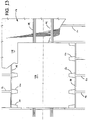
- the frame 60 is substantially rectangular in outline, with longitudinally-extending side beams 66 that are joined by a series of transverse beams 68; as can be seen in FIG. 8 , each of the transverse beams 68 is aligned axially with one of the transverse deck beams 48, so that when the lift platform is in the raised and locked position, the transverse beams of the platform correspond to and substitute structurally for the segments of the deck beams that were removed in the formation of the lift opening 38.
- the actuating mechanism 70 is mounted across one end of the frame 60, within the vertical and horizontal space 71 defined by the side beams 66 and two of the transverse beams 68.
- First and second scissors-action stabilizing mechanisms 72 are mounted along the longitudinal sides of the frame, in the spaces 74 between the side beams 66 and the headers 48.
- notches 76 are formed in the bottom edges of the two side beams, to provide clearance for the floor frames of the cargo deck when the platform is lowered into the bottom recess 32, in the position shown in FIG. 9 .
- each of the scissors-action stabilizing mechanisms includes four rigid arm members 80 arranged in upper and lower X-shaped pairs, that are joined at their ends by pivot connections 82.
- the upper end of one member in each upper pair is mounted to one of the headers 48 by a stationary pivot connection 84 (one only being visible in FIG. 9 ), while the upper end of the other member is attached by a second pivot connection 86 to a linear guide 88 that accommodates changes in distance that develop between the two pivot connections 84, 86 as the lift platform is raised/lowered.
- the lower ends of the two bottom pair members are attached by a stationary pivot connection 90 and a moving pivot connection 92 on each side of the platform, each moving pivot connection being mounted to a linear guide 94.
- the scissors-action mechanisms on the two sides of the lift platform stabilize the lift platform against side-to-side and fore-to-aft motions as it is being raised/lowered, as well as against tipping/tilting forces caused by the load.
- the rigid members are formed of any suitable rigid, high strength material, such as steel or aluminum, and are suitably tapered as shown, in the interest of minimizing weight.
- the actual raising/lowering of the lift platform is accomplished by means of cables that are attached to the pulley mechanism 70.
- cables are preferably formed of synthetic fiber rope, although any suitable non-metallic or metallic material, or combinations thereof, may be used.
- the actuating mechanism 70 includes twin ball screws 102a, 102b that span the distance between the two side beams of the frame, the ball screws being driven by an electric motor 104 and reduction gear 106.
- a paired ball nut 108 is in threaded engagement with both ball screws, and supports pulley set 110 on a common shaft that extends transversely between the individual ball nuts 112a, 112b. Rotation of the screws by the motor and reduction gear selectively moves the paired ball nut in one direction or the other (i.e., it moves towards one end or the other, depending on the direction of rotation of the motor).
- the ends of the cables are mounted to a plate 124 on the frame member 66 at one end of the actuating mechanism, and are routed over the pulleys carried on the ball nuts so that the cables are paid out or retracted as the ball nuts move one way or the other. Additional pulleys redirect the cables in a vertically, with the other ends of the cables being mounted to the stationary deck beam as noted above.
- the end plate 114 also carries the bearings 116a, 116b that support the distal ends of the ball screws.
- FIGS. 17-19 show the configuration of the pulleys and cables in greater detail:
- the assembly is shown in the retracted position, with the ball nut assembly located towards the left adjacent to the drive motor, while FIG. 19 shows the ball nut assembly moved towards the right so that the cables are paid out from the assembly in an extended position.
- the pulley set 110 that is carried on the pair of ball nuts includes first and second paired, stepped pulley units 120a, 120b.
- the cables are led in pairs -- 100a, 100b and 100c, 100d -- from the base plate 114, longitudinally (i.e., parallel to the ball screws) over the two stepped pulley units 120a, 120b, and then in reverse direction back towards the base plate.
- the cable pairs are redirected in a horizontal direction outwardly from the actuating mechanism by a set of vertical-axis stepped pulleys 122a, 122b, and are then redirected into vertical legs by horizontal-axis stepped pulley units 124a, 124b; a second vertical-axis stepped pulley unit 126 is used to lead cables 100a, 100b to the opposite end of the assembly, but is not required for the other cable pair 100c, 100d.
- the stepped pulley sets serve to ensure equal travel above the cables, i.e., the cables are routed over the larger- and smaller-diameter pulleys in each set so that the travel is the same despite the offset distance between the cables in each pair 100a, 100b and 100c, 100d.
- actuating the motor in a first direction so as to cause the ball nut assembly to move towards the motor increases the distance between the paired pulley set 110 and the base plate 114.
- This increases the length between the paired pulleys and the base plate, and the lower cable leg between the pulleys 110 in the vertical axis pulley sets 122a, 122b, so that the cables are retracted into the lift platform the latter is drawn to its raised position, as shown in FIGS. 6-8 .
- the preferred actuating system that is shown in the figures results in a 2:1 ratio of platform movement to pulley movement, which is a significant factor allowing the actuation system to be nested laterally within the platform.
- twin ball screws prevents eccentric loading on the ball nuts should a cable fail; the load on a single ball screw may increase but there would not be any induced bending.
- the use of multiple cables also provides a degree of redundancy and added safety; the cables are preferably sized so that any single cable is capable of supporting the platform against falling in the event that the other cables are damaged or fail.
- use of cables on two sides of the platform rather than at a single attachment point reduces torsion and bending loads during operation of the system.
- the power requirements of the electrical motor 104 are easily met by either ground or onboard (aircraft) sources, supplied to the motor by an electrical cable as described above.
- FIGS. 14 and 15 show more clearly the manner in which the scissors-action guide mechanisms extend and collapse as the platform is raised and lowered.
- the collapsed scissors mechanism 72 nests entirely within the height of the main passenger deck 18 itself, so that there are no projections above the floor that would interfere with use of the passenger space 130, nor below the lower edges of the lower deck beams that would interfere with use of the full volume of the lower lobe cargo compartment 132.
- the upper and lower pairs 134a, 134b of members in each of the scissors action stabilizing mechanisms is joined by a central pivot connection 136 in an X-shaped configuration.
- the adjoining ends of the upper and lower X-shaped pairs are in turn joined by pivot connections 82. All the pivot connections, including those on the upper deck (84, 86) and on the lift platform (90, 92), have axes that are aligned in the horizontal direction, so that the mechanism is able to collapse in the vertical plane while remaining stable in the horizontal plane.
- FIG. 16 shows the structure of the linear guides in greater detail, and also the manner in which the upper and lower pairs of scissors action members nest atop one another in the area between the lift platform and the stationary deck.
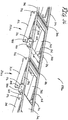
- each of the linear guide assemblies 88, 94 includes a pair of parallel, guide rails 140, those of the upper guide assembly being mounted to the headers 48 at the sides of the opening 38, and those of the lower guide assembly being mounted to the two side beams 66 of the lift deck.
- Each of the guide assemblies includes a stationary, parallel pair of T-shaped (in cross section) rails 140 that are received in corresponding parallel channels in sliding bracket members 144, so that the latter are free to slide in a horizontal direction while being supported vertically.
- the pin 92 that forms the lower sliding pivot is mounted to a downwardly projecting portion of the outboard, lower sliding bracket member, while the pivot pin of the upper pivot joint is mounted to the upper sliding bracket member.
- the axes of the upper and lower pivot pins 86, 92 are parallel to one another and are offset vertically to allow the members 80 of the upper and lower scissors action assemblies 134a, 134b to stack atop one another as noted above.
- the upper pivot pin 86 is elongated, so as to space the rigid member 80 that is connected thereto away from the sliding bracket by a distance sufficient to accommodate the neighboring rigid member of the upper pair.
- the guide rails 142 and/or the channel portions in which they are received may be formed of metal, provided with suitable lubrication. In some embodiments, however, either or both may be formed of a polymeric material having low friction and self-lubricating characteristics combined with strength and durability, such as DelrinTM, for example.
- Linear guide assemblies that have been described above have the advantages of compactness, durability and ease of maintenance. It will be understood, however, that other types of linear guide mechanisms known to those skilled in the relevant art may be employed in other embodiments of the invention.
- installation of the cargo lift system of the present invention does not significantly affect the structural integrity and load capacity of the aircraft, and of the main, passenger deck in particular, due to the lift platform becoming an integral part of the aircraft structure when in the up/stowed position.
- This is a very significant advantage since, in addition to the general loading due to passengers or cargo, the floor beams of the passenger deck carry significant lateral load in a pressurized aircraft. Consequently, it is important to maintain lateral continuity in the deck in order to ensure minimal changes to the fuselage loads during flight.
- the locking mechanisms 50 are mounted on the two longitudinal sides of the lift opening 38, at the ends of the truncated floor beams 46. Consequently, when latched to the raised lift platform, the latch mechanisms connect the ends of the beams to the transverse beams of the platform so as to essentially establish continuity for each beam across the entire deck.
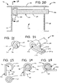
- each of the latch mechanisms 50 includes a locking cam 150 having a receiver 152 mounted at the distal end of a rotatable shaft 154.
- the opposite end 156 is mounted to an actuating linkage (not shown), such as a shaft-operated bell-crank linkage that rotates all of the cam locks simultaneously.
- a cover flange 58 projects from the header 48 over the top of the latch mechanism, to protect the mechanism and also to support the floor panel 159 (see FIG. 13 ) about the perimeter of the opening 38.
- each of the locking pins in the preferred embodiment includes a short, generally cylindrical head portion 162 having bevelled edges 164 and a flat, circular top 166, and a reduced-diameter base portion 168.
- the locking pins 160 are mounted to the edges of the lift deck 30 by welding or other suitable means.
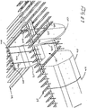
- the receiver portions of the cam latches each include a generally semi-circular receptacle area 170 that is sized and shaped to receive the cooperating pin member 160 in locking engagement therewith, and a tangentially-extending ramp portion 172 for engaging the edges of the pin member and guiding it into the receptacle area.
- a channel having a flat base 174 extends along the inside surface of the ramp portion and into the receptacle area 170, for engaging the cylindrical wall 162 of the pin member, the channel being bordered by bevelled edges 176a, 176b that cooperate with the bevelled edges 164 on the pin member.
- FIGS. 23-25 illustrate the sequential steps in engagement and locking of the latch and pin members 150, 160.
- the latch and pin members are arranged in vertical alignment, with the latch member initially being rotated to a position in which the ramp portion 172 extends in a downward direction.
- the ramp portion 172 cooperates with the surfaces of the locking pin to direct the latter into the opening 178 of the semi-circular receiving area 170.
- the pin member 160 is rotated in the direction indicated by arrow 182 so as to draw in and capture the pin member within the receiver 152.
- the pin member is supported vertically by the lower wall portion 184 of the latching member, and is restrained in the horizontal direction by the engagement of the bevelled edges 164, and 176a, 176b.
- the latch mechanism consequently transfers loads in all directions between the transverse beams of the deck and lift platform, so that the latter is, in a structural sense, integrated into the passenger deck 18 of the aircraft in the manner described above.
- latch mechanism described with reference with FIGS. 20-25 thus provides significant advantages in terms of durability and reliable operation, however, it will be understood that other forms of latch mechanism may be used in some embodiments.
- FIGS. 26A-29 illustrate a cargo lift apparatus in accordance with a second embodiment of the present invention, which is particularly suited to use with double-decker "jumbo" aircraft, but is not limited thereto.
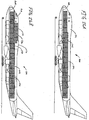
- FIG. 26A shows a conventional "jumbo" aircraft 200 having a double-decker configuration, in this case, a Boeing model 747.
- a dedicated cargo carrier palletized cargo is carried in ULDs 202 on the main deck 204 of the aircraft, i.e., the deck that would provide seating in a passenger configuration. Cargo is also carried in the lower lobe in a conventional manner.
- the upper deck of the aircraft, in the area indicated at 206, is unutilized.
- FIG. 26B shows a modified aircraft 208 having a lift apparatus 210 in accordance with the present invention installed therein, which permits additional ULDs 212 to be raised from the main deck 204 to the upper deck 214. Not only does this make it possible to carry cargo in the previously unutilized space 206, it also renders it feasible to modify the aircraft to carry additional cargo on the upper deck by extending the upper fuselage compartment as shown at 216.
- the lift apparatus 210 is broadly similar to that of the embodiment described above, in that it likewise utilizes a lift platform 220 that houses a substantially self-contained operating mechanism, and that mounts structurally to the upper deck when in the raised, stowed position.
- the lift and stabilization mechanisms are configured to accommodate the larger loads anticipated in a wide-body "jumbo" aircraft, as well as the greater height between decks and other differences in geometry.
- the lift platform 220 therefore lowers and raises between the upper and main decks 214, 204 of the aircraft, transferring ULDs 212 to/from the upper deck via the through opening 228.
- a divider panel 230 may be provided on the upper deck to section off the cargo area from other areas of the space.
- the lift platform 220 employs four cable pairs 222a-d, that are paid out and retracted at the longitudinal sides of the platform, near the front and rear comers thereof.
- the platform is stabilized by guide legs 224a, 224b that pivot downwardly and lock in a vertical position as will be described below, rather than the scissors-action stabilizer mechanism previously described.
- FIG. 28 shows the lift platform 220 and its operating mechanism in greater detail.
- the drive mechanism 232 employs horizontally-extending ball screws and nuts that are encompassed within the vertical height of the deck.
- two paired ball screw and nut assemblies 234a, 234b are provided for the two sides of the assembly, the ball screws being driven by a single, central motor 236 via a common gear box 238.
- Operation of the motor drives the two nut assemblies and their associated pulleys in opposite directions, i.e., so that they diverge outwardly towards the two side rails 240a, 240b of the platform and converge inwardly towards the motor 238, depending on the direction of rotation of the motor.
- the cable pairs 222a, 222b that are located proximate the distal ends of the ball screws are redirected in a vertical direction by horizontal axle pulley sets 242a-242b, while the other cable pairs 220c-220d are first directed towards the other corner by vertical axle pulley sets 244a-244b, and are then redirected outwardly and then upwardly by vertical and horizontal axle pulley sets 246a-246b and 248a-248b (the axes of the pulley sets may be angled slightly from vertical/horizontal as to direct the cable pairs on to the shives of the pulleys in an efficient manner).
- the platform has an inherent degree of stability due to the location of the four cable pairs 222a-222d at its corners. Moreover, because each cable (which is suitably a synthetic fiber rope, as described above) is paired with a mate, a degree of redundancy is ensured in the event that any single cable should fail.
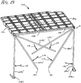
- FIG. 29 illustrates the operation of the vertical guide legs 224a-224b. As can be seen, the two legs next parallel to one another along one of the transverse edges of the lift platform when the latter is in its raised and stowed position.
- the guide legs Prior to actuation of the lift platform, however, the guide legs pivot downwardly, as indicated by arrows 254, passing progressively through positions 224a'-b' and 224a"-b", until reaching vertical alignment at position 224a"'-b"'.
- pin portions 256 on the distal ends of the legs enter sockets in receivers 256a-b on the main deck, so as to temporarily lock the guide legs in a vertical position.
- each of the guide legs 224a-b is received in one of the guide blocks 226a-b in sliding engagement therewith.
- the guide block are joined to the lift platform 220 by short stub axles 260, that project from one of the transverse edge beams 262 of the platform.
- Short, blind bores in the guide blocks receive the stub axles in rotatable engagement, enabling the legs to pivot from the horizontal, stowed position to the vertical, deployed position, and vice versa, in the manner described above.
- the nested legs are accommodated within the spaced, gap 264 between the transverse frame member of the platform and the transverse beam 266 at the edge of the deck opening.
- the guide blocks 226a-b are accommodated within downward facing openings 268 of receivers 270 mounted to the upper deck (see FIG. 30 ).
- the receiver openings accommodate rotation of the guide blocks as the stabilizer legs are pivoted between their stowed and deployed positions.
- the receivers also include socket openings (not shown) that engage reduced diameter pin portions 272 at the upper ends of the legs, and that may be driven by a motor or other suitable means through a 90 degree arc (e.g., via a gear or crank linkage) to pivot the legs between the stowed and deployed positions.
- the guide legs 224a-b are first deployed to their vertical orientation, with the pins on the lower ends of the legs being locked in the lower receivers 256a-b.
- the drive mechanism 232 of the lift platform is then actuated to lower and raise the platform, with the guide blocks 226a-b sliding along the vertical legs to stabilize the platform against any motion in a side-to-side or front-to-rear direction.
- a cutout in the underlying floor receives the lift platform when the latter is in its lowered position; when the platform has been raised and stowed, a pair of rails may be set across the cutout to span the opening.
- removing and replacing the rails involves a degree of delay, and moreover, this approach may not be satisfactory under circumstances where a more continuous floor surface is required.
- FIGS. 32-36 consequently show a translating floor assembly in accordance with the present invention, that forms a generally continuous floor surface when raised, but that can be lowered to clear the receiving area for the lift platform when heeded.
- FIG. 32 shows the floor recess 32 that receives the lift deck when it is in the lowered position, this area being formed (as noted above) by the cutaway, lowered upper edges 290 of lateral floor frames 52, that lie at a level below the floor surface that is defined by the upper edges 292 of the intact frames.
- the drop-away, translating floor assembly 294 is made up of a series of folding floor sections 296a-e that are mounted in the intercostal spaces 298 between the laterally extending floor frames 52, so that each of the cut-down frames is flanked by a pair of the folding sections.
- the assembly is shown in its lowered configuration in FIG. 33 , with the sections 296a-e folded generally flat at the bottoms of the intercostal spaces.
- the lowered sections therefore lie below the level of the cutaway edges 290, so that the recess is cleared to allow the lift platform to be lowered therein in the manner described above.
- FIG. 34 shows the floor assembly 294 in its raised position, with the series of floor sections 296a-e being unfolded and raised within their intercostal spaces so that in combination they define a floor surface that is generally continuous and level with the main floor surface that is defined by the upper edges 300 of the intact floor frames.
- each of the folding floor sections includes a series of short, longitudinally extending plate-like deck segments 302 supported at the ends by paired legs 304. The upper ends of the legs are joined by elongate rod members 306 that are pivotably mounted to the legs and that extend laterally within the intercostal space.
- the lower ends of the legs are pivotably mounted to brackets (not shown) or other fittings towards the bottom of the intercostal space.
- the panels and legs thus form individual segments 308 that, being linked by the lateral rods 306, move in concert as the floor section is raised/lowered.
- the deck segments 302 are mounted fixedly to the lateral rod members 306, in coplanar relationship therewith, so that when the head of the section is in its raised position (as shown in FIG. 35A ), the deck segments all lie horizontal in side-by-side relationship, level with the main floor surface.
- the deck segments (and the rod members 306) remain horizontal, but the support legs 304 pivot downwardly to lower them towards the bottom of the intercostal space.
- the deck segments 302 are comparatively narrow and are separated from one another by a series of gaps; in other instances, such as for use in the deck of a passenger area, the edges of the deck segments may meet, or the individual segments may be replaced with one or more laterally extending panels, so as to form a continuous, uninterrupted floor surface when in the raised position.
- Raising and lowering of the section is accomplished, in the illustrated embodiment, by means of a pair of actuator segments 310a, 310b.
- the actuator segments each include a pair of support legs 312 having an open-sided channel configuration, which configuration can be used for the legs 304 of the other, unpowered segments as well.
- An elongate actuation link 314 is received in the open side of each of the legs of the powered segments, with its upper end, being joined to the upper end of the leg by a horizontal axis pivot pin 316 that also serves to pivotably mount the upper end of the leg to one of the rod members 306 of the upper frame; in the embodiment that is illustrated, the rod members are spanned at the upper ends of legs 312 by longitudinal seat track segments, rather than planar deck segments, allowing seats to be installed thereon when the assembly is in its raised position.
- the lower end of each pivot link is joined to an actuation arm 316 by a second pivot pin 318, with the actuation arm in turn being fixedly mounted to an end 320 of a torque tube 322.
- the pivot pin 318 for the lower end of the actuation link is spaced from the end of the torque tube, so as to create a crank-arm when the torque tube is rotated.
- the actuation arm suitably has a channel configuration, with the end of the actuation link being received in the interior of the channel and the pivot pin 318 spanning between the sides thereof.
- Rotation of the torque tubes causes the actuation links to draw on the upper ends of the support legs 312, pivoting the legs about their lower attachment points 324 and thus raising the upper frame and deck segments to their elevated position as described above.
- the lower ends of the actuation links rotate to an over center position (i.e., to a position on the opposite side of the torque tube from the support leg), locking the assembly in its raised position.
- the assembly is lowered by rotating the torque tubes in an opposite direction, which raises the ends of the actuation links from their over center positions, releasing the assembly from its locked configuration, and pivots the legs downwardly towards a horizontal orientation.
- the torque tubes may be rotated by one or more motors (not shown) or other suitable drive devices. Rotation of the torque tubes is preferably linked so that all of the sections in the floor assembly 294 rise/fall simultaneously with minimal delay.
- the translating floor assembly thus allows the lift assembly of the present invention to be used with no reduction in allowable floor space in the aircraft.
- the embodiment that has been described with reference to FIGS. 32-36 provides several significant advantages, particularly in terms of providing a compact, modulized system that is economical to produce and is relatively light in weight. It will be understood, however, that other types of temporary/moveable floor structures and mechanisms may be employed in conjunction with the lift platform of the present invention, as has been described above.
Landscapes
- Engineering & Computer Science (AREA)
- Aviation & Aerospace Engineering (AREA)
- Mechanical Engineering (AREA)
- Auxiliary Methods And Devices For Loading And Unloading (AREA)
- Elevator Door Apparatuses (AREA)
- Ladders (AREA)
- Connection Of Plates (AREA)
- Elevator Control (AREA)
- Cage And Drive Apparatuses For Elevators (AREA)
Claims (22)
- Appareil pour transférer un chargement entre un pont supérieur (18) et un pont inférieur (16) d'un avion (10), ledit appareil comprenant :une plateforme de levage (30) qui peut être reçue dans une ouverture débouchante (38) formée dans ledit pont supérieur (18) dudit avion (10), ladite plateforme de levage (30) ayant une surface supérieure pour supporter une charge de chargement sur cette dernière ; etdes moyens pour abaisser et lever ladite plateforme de levage (30) entre ledit pont supérieur (18) et ledit pont inférieur (16) afin de transférer les charges du chargement à et dudit pont supérieur (18) via ladite ouverture débouchante ; caractérisé en ce que l'appareil comprend en outre des moyens pour fixer sélectivement les bords de ladite plateforme de levage (30) sur ledit pont supérieur (18) en mise en prise de support de charge avec ce dernier, lorsque ladite plateforme de levage (30) est levée et arrimée dans ladite ouverture débouchante (38) de sorte que ladite plateforme de levage (30) peut partager une charge structurelle dudit pont supérieur (18) pendant l'opération de vol dudit avion (10).
- Appareil selon la revendication 1, dans lequel lesdits moyens pour fixer sélectivement les bords de ladite plateforme de levage sur ledit pont supérieur (18) en mise en prise de support de charge avec ce dernier, comprennent :des moyens pour fixer sélectivement des premier et second bords latéraux s'étendant longitudinalement de ladite plate forme de levage (30) aux premier et second bords latéraux s'étendant longitudinalement de ladite ouverture débouchante (38) de sorte que ladite plateforme de levage (30) partage la charge structurelle dudit pont supérieur (18) dans une direction latérale pendant l'opération de vol dudit avion (10).
- Appareil selon la revendication 2, dans lequel lesdits moyens pour fixer sélectivement lesdits bords latéraux de ladite plateforme de levage (30) auxdits bords latéraux de ladite ouverture débouchante (38) comprennent :au moins un ensemble de blocage (50) sur chacun desdits bords latéraux de ladite plateforme de levage (30), chaque ensemble de blocage (50) comprenant :une première partie de blocage qui est montée sur un bord latéral longitudinal de ladite plateforme de levage (30) ; etune seconde partie de blocage qui est montée sur un bord latéral longitudinal de ladite ouverture débouchante (38) pour établir la mise en prise de support de charge avec ladite première partie de blocage sur ladite plateforme de levage (30).
- Appareil selon la revendication 3, dans lequel ladite première partie de blocage comprend un élément de broche (160) qui s'étend dans une direction latérale à partir d'un bord latéral de ladite ouverture débouchante (38) et ladite seconde partie de blocage comprend un verrou rotatif (150) qui reçoit ledit élément de broche (160) en mise de prise de support de charge latérale et verticale avec ce dernier.
- Appareil selon la revendication 3, dans lequel lesdits bords latéraux de ladite ouverture débouchante (38) s'étendent sur une pluralité de poutres latérales tronquées (46) dudit pont supérieur (18) ; et dans lequel ladite plateforme de levage (30) comprend :une pluralité de poutres latérales (68) qui s'étendent sur une largeur de ladite plateforme de levage (30) et qui sont alignées axialement avec lesdites poutres tronquées (46) dudit pont supérieur (18) lorsque ladite plateforme de levage (30) est levée et arrimée dans ladite ouverture débouchante (38).
- Appareil selon la revendication 5, dans lequel ledit au moins un ensemble de blocage comprend :une pluralité desdits ensembles de blocage (50), chacun desdits ensembles de blocage (50) étant positionné au niveau d'une jonction axiale entre l'une desdites poutres tronquées (46) dudit pont supérieur (18) et l'une desdites poutres latérales (68) de ladite plateforme de levage (30) lorsque ladite plateforme de levage (30) est levée et arrimée dans ladite ouverture débouchante (38).
- Appareil selon la revendication 6, comprenant en outre :des éléments de boutisse (48) s'étendant longitudinalement montés d'un côté à l'autre desdites extrémités desdites poutres tronquées (46) dudit pont supérieur (18), et deux poutres latérales intactes dudit pont supérieur (18) à l'avant et après les extrémités de ladite ouverture débouchante (38).
- Appareil selon la revendication 1, dans lequel lesdits moyens pour abaisser et lever ladite plateforme de levage comprennent :un mécanisme de levage (62) comprenant :au moins un câble de levage (100) ; etun ensemble d'entraînement (70) pour étendre et rétracter sélectivement ledit câble de levage (100) afin d'abaisser et de lever ladite plateforme de levage (30) ;sensiblement tout ledit ensemble d'entraînement (70) étant logé à l'intérieur de ladite plateforme de levage (30).
- Appareil selon la revendication 8, dans lequel ledit ensemble d'entraînement (70) comprend :un point d'ancrage pour une extrémité dudit au moins un câble de levage (100) ;au moins une vis sphérique (102a, 102b) et un écrou (108, 112a, 112b) en mise en prise d'entraînement coopérative, ledit écrou sphérique (108, 112a, 112b) étant positionné à une distance éloignée dudit point d'ancrage ;au moins une poulie (110) montée sur ledit écrou sphérique (108, 112a, 112b), ledit câble de levage (100) étant acheminé sur ladite poulie (110) à partir dudit point d'ancrage ; etun moteur (104) pour faire tourner, de manière réversible, ladite vis sphérique (102a, 102b), dans une première direction qui raccourcit ladite distance entre ladite poulie (100) et ledit point d'ancrage afin d'étendre ledit câble (100) à partir de ladite plateforme de levage (30), et dans une seconde direction qui augmente ladite distance entre ladite poulie (110) et ledit point d'ancrage afin de rétracter ledit câble (100) dans ladite plateforme de levage (30).
- Appareil selon la revendication 9, dans lequel ladite au moins une vis sphérique (102a, 102b) et l'écrou (108, 112a, 112b) sont montés pour s'étendre généralement horizontalement à l'intérieur d'une hauteur intérieure de ladite plateforme de levage (30).
- Appareil selon la revendication 8, comprenant en outre :des moyens pour stabiliser ladite plateforme de levage (30) lorsque ladite plateforme de levage (30) est abaissée et levée entre lesdits ponts supérieur et inférieur (18, 16) dudit avion (10).
- Appareil selon la revendication 8, dans lequel lesdits moyens pour stabiliser ladite plateforme de levage (30) comprennent :des premier et second ensembles de stabilisateur à action de cisaillement (134a, 134b) sur les côtés s'étendant longitudinalement de ladite plateforme de levage (30), chacun desdits ensembles de stabilisateur (134a, 134b) comprenant :au moins une paire d'éléments de bras rigides (80) assemblés dans une configuration en forme de X par un point de pivot central (136) ;des premier et second points de fixation supérieurs (84, 86) sur ledit élément de bras (80) qui sont montés de manière pivotante sur ledit pont supérieur (18) dudit avion (10) ; etdes premier et second points de fixation inférieurs (90, 92) sur lesdits éléments de bras (80) qui sont montés de manière pivotante sur lesdits côtés s'étendant longitudinalement de ladite plateforme de levage (30).
- Appareil selon la revendication 12, dans lequel lesdits premier et second points de fixation (84, 86, 90, 92) sur lesdits éléments de bras (80) comprennent chacun :un raccordement de pivot fixe ; etun raccordement de pivot coulissant qui accepte les augmentations et les réductions de distance entre lesdits premier et second points de fixation (84, 86, 90, 92) lorsque ledit pont de levage (30) est levé et abaissé.
- Appareil selon la revendication 13, dans lequel lesdits raccordements de pivot coulissants comprennent chacun :au moins un rail de guidage (140) qui s'étend dans une direction sensiblement horizontale ;un élément de support (144) ayant au moins une partie de canal qui reçoit ledit rail de guidage (140) en mise en prise coulissante avec ce dernier, de sorte que ledit élément de support (144) est libre de coulisser horizontalement tout en étant supporté verticalement ; etun raccordement de pivot assemblant une extrémité de l'un desdits éléments de patte rigides audit élément de support (144).
- Appareil selon la revendication 13, comprenant en outre :des premier et second espaces formés entre lesdits bords latéraux s'étendant longitudinalement de ladite plateforme de levage (30) et les bords s'étendant longitudinalement de ladite ouverture débouchante (38), dans lequel lesdits éléments de patte rigides dudit ensemble de stabilisation (72) s'emboîtent lorsque ladite plateforme de levage (30) est levée et arrimée dans ladite ouverture débouchante (38).
- Appareil selon la revendication 8, dans lequel lesdits moyens pour stabiliser ladite plateforme de levage (30) comprennent :des première et seconde pattes de stabilisateur pour s'étendre sensiblement verticalement entre lesdits ponts supérieur et inférieur (18, 16) ; etdes premier et second éléments de guidage qui sont montés sur ladite plateforme de levage (30) et sont en mise en prise coulissante longitudinale avec lesdits pattes de stabilisateur.
- Appareil selon la revendication 16, dans lequel lesdites première et seconde pattes de stabilisateur comprennent :des premier et second éléments de patte allongés qui peuvent sélectivement pivoter à partir d'une première position horizontale dans laquelle lesdits éléments de patte s'emboîtent le long de ladite plateforme de levage (30), lorsque ladite plateforme de levage (30) est dans ladite position levée et arrimée ; et une seconde position verticale dans laquelle lesdits éléments de patte stabilisent ladite plateforme de levage (30) lorsque ladite plateforme de levage (30) est abaissée et levée entre lesdits ponts supérieur et inférieur (18, 16).
- Avion comprenant un pont inférieur et ayant un appareil pour transférer le chargement selon la revendication 1, comprenant en outre :un évidement (32) dans ledit pont inférieur (16) dudit avion (10) pour recevoir ladite plateforme de levage (30) à l'intérieur de ce dernier, de sorte que ladite surface supérieure de ladite plateforme de levage (30) s'étend sensiblement de niveau avec une surface supérieure dudit pont inférieur (16) lorsque ladite plateforme de levage (30) est abaissée dans ce dernier.
- Appareil selon la revendication 18, dans lequel ledit évidement (32) dans ledit pont inférieur (16) dudit avion (10) comprend :une zone dudit pont inférieur (16) dudit avion (10) dans laquelle des bords supérieurs des bâtis de plancher ont été retirés afin de former ledit évidement à l'intérieur de cette dernière.
- Appareil selon la revendication 19, comprenant en outre :un ensemble de plancher de translation (294) monté dans ladite zone dudit pont inférieur (16) dudit avion (10), ledit ensemble de plancher de translation (294) ayant une première position qui définit une surface de plancher qui s'étend sur ledit évidement généralement de niveau avec ladite surface supérieure dudit pont inférieur (16), et une seconde position qui dégage ledit évidement (32) pour recevoir ladite plateforme de levage (30) dans ledit pont inférieur (16) dudit avion (10).
- Appareil selon la revendication 20, dans lequel ledit ensemble de plancher de translation (294) comprend :une pluralité de sections de plancher pliantes (296a-e), chacune desdites sections de plancher pliantes (296a-e) comprenant :un bâti s'étendant latéralement (52) qui est reçu dans un espace intercostal (298) entre lesdits bâtis de plancher dudit pont inférieur (16) ;au moins un segment de pont (302) monté sur ledit bâti pour s'étendre sensiblement de niveau avec ladite surface supérieure dudit pont inférieur (16), lorsque ledit bâti est dans une position levée ;une pluralité d'éléments de patte pliants (304), chacun desdits éléments de patte (304) ayant une extrémité supérieure qui est montée de manière pivotante sur ledit bâti et une extrémité inférieure qui est montée de manière pivotante sur ledit pont inférieur (16) dans ledit espace intercostal (298) entre lesdits bâtis de plancher ; etdes moyens pour faire pivoter sélectivement lesdits éléments de patte (304) entre une orientation généralement verticale dans laquelle ledit bâti est supporté sensiblement de niveau avec ladite surface dudit pont inférieur (16) et une orientation généralement horizontale dans laquelle ledit bâti tombe dans ledit espace intercostal (298) afin de dégager ledit évidement pour recevoir ladite plateforme de levage (30) dans le pont inférieur (16).
- Appareil selon la revendication 21, dans lequel lesdits moyens pour faire pivoter sélectivement lesdits éléments de patte (304) comprennent :au moins une liaison d'actionnement (314) ayant une extrémité supérieure qui est montée sur une extrémité supérieure de l'un desdits éléments de patte pliants (304), et une extrémité inférieure qui est montée sur un bras d'actionnement (316) ;un tube de couple (322) qui est monté sur ledit bras d'actionnement (316) ; etdes moyens pour faire tourner de manière réversible ledit tube de couple (322) dans une première direction de sorte que ladite liaison d'actionnement (314) tire ledit élément de patte (304) dans ladite orientation verticale, et une seconde direction de sorte que ladite liaison d'actionnement (314) abaisse ledit élément de patte (304) dans ladite orientation généralement horizontale.
Applications Claiming Priority (1)
| Application Number | Priority Date | Filing Date | Title |
|---|---|---|---|
| PCT/US2010/002984 WO2012067595A1 (fr) | 2010-11-15 | 2010-11-15 | Élévateur de fret compact pour avion commercial |
Publications (2)
| Publication Number | Publication Date |
|---|---|
| EP2640635A1 EP2640635A1 (fr) | 2013-09-25 |
| EP2640635B1 true EP2640635B1 (fr) | 2017-02-15 |
Family
ID=44624914
Family Applications (1)
| Application Number | Title | Priority Date | Filing Date |
|---|---|---|---|
| EP10784359.1A Active EP2640635B1 (fr) | 2010-11-15 | 2010-11-15 | Élévateur de fret compact pour avion commercial |
Country Status (6)
| Country | Link |
|---|---|
| EP (1) | EP2640635B1 (fr) |
| CN (1) | CN103298693B (fr) |
| BR (1) | BR112013011019A2 (fr) |
| IL (1) | IL225478A (fr) |
| SG (1) | SG189290A1 (fr) |
| WO (1) | WO2012067595A1 (fr) |
Families Citing this family (1)
| Publication number | Priority date | Publication date | Assignee | Title |
|---|---|---|---|---|
| CN110589523A (zh) * | 2019-09-03 | 2019-12-20 | 中国航空工业集团公司西安飞机设计研究所 | 一种航空货物装卸装置 |
Family Cites Families (6)
| Publication number | Priority date | Publication date | Assignee | Title |
|---|---|---|---|---|
| US3019757A (en) * | 1959-05-07 | 1962-02-06 | Wells Fargo Bank Americ Compan | Vertically adjustable ship decks |
| IL96799A (en) * | 1990-12-27 | 1995-11-27 | Fuselage Eng Services | Aircraft fuselage construction including food carrier |
| IL103217A (en) * | 1992-09-18 | 1995-10-31 | Fuselage Eng Services | Vehicle cabin construction |
| RU2088477C1 (ru) * | 1995-03-27 | 1997-08-27 | Акционерное общество открытого типа "Авиационный научно-технический комплекс им.А.Н.Туполева" | Самолет |
| EP1873059A3 (fr) * | 2000-06-06 | 2012-04-11 | Mitsubishi Heavy Industries, Ltd. | Avion doté de cabines à plusieurs niveaux pour fret ou passagers et procédé de chargement de fret dans ledit avion |
| US8011617B2 (en) * | 2005-06-17 | 2011-09-06 | Curry James M | Compact cargo lift for commerical aircraft |
-
2010
- 2010-11-15 SG SG2013025671A patent/SG189290A1/en unknown
- 2010-11-15 EP EP10784359.1A patent/EP2640635B1/fr active Active
- 2010-11-15 WO PCT/US2010/002984 patent/WO2012067595A1/fr not_active Ceased
- 2010-11-15 CN CN201080070152.9A patent/CN103298693B/zh active Active
- 2010-11-15 BR BR112013011019-8A patent/BR112013011019A2/pt not_active Application Discontinuation
-
2013
- 2013-03-24 IL IL225478A patent/IL225478A/en active IP Right Grant
Also Published As
| Publication number | Publication date |
|---|---|
| WO2012067595A1 (fr) | 2012-05-24 |
| CN103298693B (zh) | 2016-01-13 |
| CN103298693A (zh) | 2013-09-11 |
| SG189290A1 (en) | 2013-05-31 |
| BR112013011019A2 (pt) | 2020-09-01 |
| EP2640635A1 (fr) | 2013-09-25 |
| IL225478A0 (en) | 2013-06-27 |
| IL225478A (en) | 2017-01-31 |
Similar Documents
| Publication | Publication Date | Title |
|---|---|---|
| US20120126056A1 (en) | Compact cargo lift for commercial aircraft | |
| EP2630037B1 (fr) | Système pour le stockage par le dessus de conteneurs de fret dans un lobe supérieur d'aéronef | |
| EP1211174B1 (fr) | Aeronef comportant plusieurs cabines superieures et inferieures faisant office de compartiment a marchandises ou de cabines a passagers, et procede de chargement de marchandises sur un aeronef | |
| US8979025B1 (en) | Compact cargo lift for commercial aircraft | |
| US6302358B1 (en) | Quick Change system and method for converting an aircraft from a cargo mode to a passenger mode and vice versa | |
| US7699267B2 (en) | Cargo aircraft | |
| EP3816037A1 (fr) | Système d'avion cargo et système de conteneurs | |
| US12240587B2 (en) | Aircraft fuselage assembly with a cargo floor assembly | |
| US6616100B2 (en) | Cargo loading means for short body airplanes | |
| EP2640635B1 (fr) | Élévateur de fret compact pour avion commercial | |
| EP3865396A1 (fr) | Aéronef de transport du fret et des personnes, conteneur de transport, procédé de chargement d'un avion et procédé de reconfiguration d'un aéronef | |
| RU2285637C2 (ru) | Грузовая кабина транспортного самолета преимущественно ан-124-100 | |
| US9193459B2 (en) | Unloading and loading of aircraft | |
| HK1107800B (en) | Cargo aircraft | |
| HK1107800A (en) | Cargo aircraft |
Legal Events
| Date | Code | Title | Description |
|---|---|---|---|
| PUAI | Public reference made under article 153(3) epc to a published international application that has entered the european phase |
Free format text: ORIGINAL CODE: 0009012 |
|
| 17P | Request for examination filed |
Effective date: 20130610 |
|
| AK | Designated contracting states |
Kind code of ref document: A1 Designated state(s): AL AT BE BG CH CY CZ DE DK EE ES FI FR GB GR HR HU IE IS IT LI LT LU LV MC MK MT NL NO PL PT RO RS SE SI SK SM TR |
|
| DAX | Request for extension of the european patent (deleted) | ||
| GRAP | Despatch of communication of intention to grant a patent |
Free format text: ORIGINAL CODE: EPIDOSNIGR1 |
|
| INTG | Intention to grant announced |
Effective date: 20151222 |
|
| GRAP | Despatch of communication of intention to grant a patent |
Free format text: ORIGINAL CODE: EPIDOSNIGR1 |
|
| INTG | Intention to grant announced |
Effective date: 20160517 |
|
| GRAS | Grant fee paid |
Free format text: ORIGINAL CODE: EPIDOSNIGR3 |
|
| GRAA | (expected) grant |
Free format text: ORIGINAL CODE: 0009210 |
|
| AK | Designated contracting states |
Kind code of ref document: B1 Designated state(s): AL AT BE BG CH CY CZ DE DK EE ES FI FR GB GR HR HU IE IS IT LI LT LU LV MC MK MT NL NO PL PT RO RS SE SI SK SM TR |
|
| REG | Reference to a national code |
Ref country code: CH Ref legal event code: EP Ref country code: GB Ref legal event code: FG4D |
|
| REG | Reference to a national code |
Ref country code: IE Ref legal event code: FG4D |
|
| REG | Reference to a national code |
Ref country code: AT Ref legal event code: REF Ref document number: 867729 Country of ref document: AT Kind code of ref document: T Effective date: 20170315 |
|
| REG | Reference to a national code |
Ref country code: DE Ref legal event code: R096 Ref document number: 602010040108 Country of ref document: DE |
|
| REG | Reference to a national code |
Ref country code: NL Ref legal event code: MP Effective date: 20170215 |
|
| REG | Reference to a national code |
Ref country code: LT Ref legal event code: MG4D |
|
| REG | Reference to a national code |
Ref country code: AT Ref legal event code: MK05 Ref document number: 867729 Country of ref document: AT Kind code of ref document: T Effective date: 20170215 |
|
| PG25 | Lapsed in a contracting state [announced via postgrant information from national office to epo] |
Ref country code: FI Free format text: LAPSE BECAUSE OF FAILURE TO SUBMIT A TRANSLATION OF THE DESCRIPTION OR TO PAY THE FEE WITHIN THE PRESCRIBED TIME-LIMIT Effective date: 20170215 Ref country code: LT Free format text: LAPSE BECAUSE OF FAILURE TO SUBMIT A TRANSLATION OF THE DESCRIPTION OR TO PAY THE FEE WITHIN THE PRESCRIBED TIME-LIMIT Effective date: 20170215 Ref country code: HR Free format text: LAPSE BECAUSE OF FAILURE TO SUBMIT A TRANSLATION OF THE DESCRIPTION OR TO PAY THE FEE WITHIN THE PRESCRIBED TIME-LIMIT Effective date: 20170215 Ref country code: GR Free format text: LAPSE BECAUSE OF FAILURE TO SUBMIT A TRANSLATION OF THE DESCRIPTION OR TO PAY THE FEE WITHIN THE PRESCRIBED TIME-LIMIT Effective date: 20170516 Ref country code: NO Free format text: LAPSE BECAUSE OF FAILURE TO SUBMIT A TRANSLATION OF THE DESCRIPTION OR TO PAY THE FEE WITHIN THE PRESCRIBED TIME-LIMIT Effective date: 20170515 |
|
| PG25 | Lapsed in a contracting state [announced via postgrant information from national office to epo] |
Ref country code: BG Free format text: LAPSE BECAUSE OF FAILURE TO SUBMIT A TRANSLATION OF THE DESCRIPTION OR TO PAY THE FEE WITHIN THE PRESCRIBED TIME-LIMIT Effective date: 20170515 Ref country code: SE Free format text: LAPSE BECAUSE OF FAILURE TO SUBMIT A TRANSLATION OF THE DESCRIPTION OR TO PAY THE FEE WITHIN THE PRESCRIBED TIME-LIMIT Effective date: 20170215 Ref country code: LV Free format text: LAPSE BECAUSE OF FAILURE TO SUBMIT A TRANSLATION OF THE DESCRIPTION OR TO PAY THE FEE WITHIN THE PRESCRIBED TIME-LIMIT Effective date: 20170215 Ref country code: ES Free format text: LAPSE BECAUSE OF FAILURE TO SUBMIT A TRANSLATION OF THE DESCRIPTION OR TO PAY THE FEE WITHIN THE PRESCRIBED TIME-LIMIT Effective date: 20170215 Ref country code: AT Free format text: LAPSE BECAUSE OF FAILURE TO SUBMIT A TRANSLATION OF THE DESCRIPTION OR TO PAY THE FEE WITHIN THE PRESCRIBED TIME-LIMIT Effective date: 20170215 Ref country code: NL Free format text: LAPSE BECAUSE OF FAILURE TO SUBMIT A TRANSLATION OF THE DESCRIPTION OR TO PAY THE FEE WITHIN THE PRESCRIBED TIME-LIMIT Effective date: 20170215 Ref country code: RS Free format text: LAPSE BECAUSE OF FAILURE TO SUBMIT A TRANSLATION OF THE DESCRIPTION OR TO PAY THE FEE WITHIN THE PRESCRIBED TIME-LIMIT Effective date: 20170215 Ref country code: PT Free format text: LAPSE BECAUSE OF FAILURE TO SUBMIT A TRANSLATION OF THE DESCRIPTION OR TO PAY THE FEE WITHIN THE PRESCRIBED TIME-LIMIT Effective date: 20170615 |
|
| PG25 | Lapsed in a contracting state [announced via postgrant information from national office to epo] |
Ref country code: SK Free format text: LAPSE BECAUSE OF FAILURE TO SUBMIT A TRANSLATION OF THE DESCRIPTION OR TO PAY THE FEE WITHIN THE PRESCRIBED TIME-LIMIT Effective date: 20170215 Ref country code: RO Free format text: LAPSE BECAUSE OF FAILURE TO SUBMIT A TRANSLATION OF THE DESCRIPTION OR TO PAY THE FEE WITHIN THE PRESCRIBED TIME-LIMIT Effective date: 20170215 Ref country code: EE Free format text: LAPSE BECAUSE OF FAILURE TO SUBMIT A TRANSLATION OF THE DESCRIPTION OR TO PAY THE FEE WITHIN THE PRESCRIBED TIME-LIMIT Effective date: 20170215 Ref country code: IT Free format text: LAPSE BECAUSE OF FAILURE TO SUBMIT A TRANSLATION OF THE DESCRIPTION OR TO PAY THE FEE WITHIN THE PRESCRIBED TIME-LIMIT Effective date: 20170215 Ref country code: CZ Free format text: LAPSE BECAUSE OF FAILURE TO SUBMIT A TRANSLATION OF THE DESCRIPTION OR TO PAY THE FEE WITHIN THE PRESCRIBED TIME-LIMIT Effective date: 20170215 |
|
| REG | Reference to a national code |
Ref country code: FR Ref legal event code: PLFP Year of fee payment: 8 |
|
| REG | Reference to a national code |
Ref country code: DE Ref legal event code: R097 Ref document number: 602010040108 Country of ref document: DE |
|
| PG25 | Lapsed in a contracting state [announced via postgrant information from national office to epo] |
Ref country code: DK Free format text: LAPSE BECAUSE OF FAILURE TO SUBMIT A TRANSLATION OF THE DESCRIPTION OR TO PAY THE FEE WITHIN THE PRESCRIBED TIME-LIMIT Effective date: 20170215 Ref country code: PL Free format text: LAPSE BECAUSE OF FAILURE TO SUBMIT A TRANSLATION OF THE DESCRIPTION OR TO PAY THE FEE WITHIN THE PRESCRIBED TIME-LIMIT Effective date: 20170215 Ref country code: SM Free format text: LAPSE BECAUSE OF FAILURE TO SUBMIT A TRANSLATION OF THE DESCRIPTION OR TO PAY THE FEE WITHIN THE PRESCRIBED TIME-LIMIT Effective date: 20170215 |
|
| PLBE | No opposition filed within time limit |
Free format text: ORIGINAL CODE: 0009261 |
|
| STAA | Information on the status of an ep patent application or granted ep patent |
Free format text: STATUS: NO OPPOSITION FILED WITHIN TIME LIMIT |
|
| 26N | No opposition filed |
Effective date: 20171116 |
|
| PG25 | Lapsed in a contracting state [announced via postgrant information from national office to epo] |
Ref country code: SI Free format text: LAPSE BECAUSE OF FAILURE TO SUBMIT A TRANSLATION OF THE DESCRIPTION OR TO PAY THE FEE WITHIN THE PRESCRIBED TIME-LIMIT Effective date: 20170215 |
|
| PG25 | Lapsed in a contracting state [announced via postgrant information from national office to epo] |
Ref country code: MC Free format text: LAPSE BECAUSE OF FAILURE TO SUBMIT A TRANSLATION OF THE DESCRIPTION OR TO PAY THE FEE WITHIN THE PRESCRIBED TIME-LIMIT Effective date: 20170215 |
|
| PG25 | Lapsed in a contracting state [announced via postgrant information from national office to epo] |
Ref country code: LI Free format text: LAPSE BECAUSE OF NON-PAYMENT OF DUE FEES Effective date: 20171130 Ref country code: CH Free format text: LAPSE BECAUSE OF NON-PAYMENT OF DUE FEES Effective date: 20171130 |
|
| PG25 | Lapsed in a contracting state [announced via postgrant information from national office to epo] |
Ref country code: LU Free format text: LAPSE BECAUSE OF NON-PAYMENT OF DUE FEES Effective date: 20171115 |
|
| REG | Reference to a national code |
Ref country code: BE Ref legal event code: MM Effective date: 20171130 |
|
| REG | Reference to a national code |
Ref country code: IE Ref legal event code: MM4A |
|
| PG25 | Lapsed in a contracting state [announced via postgrant information from national office to epo] |
Ref country code: IE Free format text: LAPSE BECAUSE OF NON-PAYMENT OF DUE FEES Effective date: 20171115 |
|
| PG25 | Lapsed in a contracting state [announced via postgrant information from national office to epo] |
Ref country code: BE Free format text: LAPSE BECAUSE OF NON-PAYMENT OF DUE FEES Effective date: 20171130 |
|
| PG25 | Lapsed in a contracting state [announced via postgrant information from national office to epo] |
Ref country code: HU Free format text: LAPSE BECAUSE OF FAILURE TO SUBMIT A TRANSLATION OF THE DESCRIPTION OR TO PAY THE FEE WITHIN THE PRESCRIBED TIME-LIMIT; INVALID AB INITIO Effective date: 20101115 |
|
| PG25 | Lapsed in a contracting state [announced via postgrant information from national office to epo] |
Ref country code: CY Free format text: LAPSE BECAUSE OF NON-PAYMENT OF DUE FEES Effective date: 20170215 |
|
| PG25 | Lapsed in a contracting state [announced via postgrant information from national office to epo] |
Ref country code: MK Free format text: LAPSE BECAUSE OF FAILURE TO SUBMIT A TRANSLATION OF THE DESCRIPTION OR TO PAY THE FEE WITHIN THE PRESCRIBED TIME-LIMIT Effective date: 20170215 |
|
| PG25 | Lapsed in a contracting state [announced via postgrant information from national office to epo] |
Ref country code: TR Free format text: LAPSE BECAUSE OF FAILURE TO SUBMIT A TRANSLATION OF THE DESCRIPTION OR TO PAY THE FEE WITHIN THE PRESCRIBED TIME-LIMIT Effective date: 20170215 |
|
| PG25 | Lapsed in a contracting state [announced via postgrant information from national office to epo] |
Ref country code: AL Free format text: LAPSE BECAUSE OF FAILURE TO SUBMIT A TRANSLATION OF THE DESCRIPTION OR TO PAY THE FEE WITHIN THE PRESCRIBED TIME-LIMIT Effective date: 20170215 Ref country code: IS Free format text: LAPSE BECAUSE OF FAILURE TO SUBMIT A TRANSLATION OF THE DESCRIPTION OR TO PAY THE FEE WITHIN THE PRESCRIBED TIME-LIMIT Effective date: 20170615 |
|
| REG | Reference to a national code |
Ref country code: DE Ref legal event code: R082 Ref document number: 602010040108 Country of ref document: DE Representative=s name: HL KEMPNER PATENTANWAELTE, SOLICITORS (ENGLAND, DE Ref country code: DE Ref legal event code: R082 Ref document number: 602010040108 Country of ref document: DE Representative=s name: HL KEMPNER PARTG MBB, DE Ref country code: DE Ref legal event code: R082 Ref document number: 602010040108 Country of ref document: DE Representative=s name: HL KEMPNER PATENTANWALT, RECHTSANWALT, SOLICIT, DE |
|
| PGFP | Annual fee paid to national office [announced via postgrant information from national office to epo] |
Ref country code: DE Payment date: 20251121 Year of fee payment: 16 |
|
| PGFP | Annual fee paid to national office [announced via postgrant information from national office to epo] |
Ref country code: GB Payment date: 20251124 Year of fee payment: 16 |
|
| PGFP | Annual fee paid to national office [announced via postgrant information from national office to epo] |
Ref country code: FR Payment date: 20251120 Year of fee payment: 16 |
|
| PGFP | Annual fee paid to national office [announced via postgrant information from national office to epo] |
Ref country code: MT Payment date: 20251113 Year of fee payment: 16 |