EP2640929B1 - Ventilanordnung - Google Patents
Ventilanordnung Download PDFInfo
- Publication number
- EP2640929B1 EP2640929B1 EP11787929.6A EP11787929A EP2640929B1 EP 2640929 B1 EP2640929 B1 EP 2640929B1 EP 11787929 A EP11787929 A EP 11787929A EP 2640929 B1 EP2640929 B1 EP 2640929B1
- Authority
- EP
- European Patent Office
- Prior art keywords
- flow path
- housing
- bypass
- barrier member
- flow
- Prior art date
- Legal status (The legal status is an assumption and is not a legal conclusion. Google has not performed a legal analysis and makes no representation as to the accuracy of the status listed.)
- Active
Links
Images

Classifications
-
- E—FIXED CONSTRUCTIONS
- E21—EARTH OR ROCK DRILLING; MINING
- E21B—EARTH OR ROCK DRILLING; OBTAINING OIL, GAS, WATER, SOLUBLE OR MELTABLE MATERIALS OR A SLURRY OF MINERALS FROM WELLS
- E21B34/00—Valve arrangements for boreholes or wells
- E21B34/06—Valve arrangements for boreholes or wells in wells
-
- E—FIXED CONSTRUCTIONS
- E21—EARTH OR ROCK DRILLING; MINING
- E21B—EARTH OR ROCK DRILLING; OBTAINING OIL, GAS, WATER, SOLUBLE OR MELTABLE MATERIALS OR A SLURRY OF MINERALS FROM WELLS
- E21B34/00—Valve arrangements for boreholes or wells
- E21B34/06—Valve arrangements for boreholes or wells in wells
- E21B34/063—Valve or closure with destructible element, e.g. frangible disc
-
- E—FIXED CONSTRUCTIONS
- E21—EARTH OR ROCK DRILLING; MINING
- E21B—EARTH OR ROCK DRILLING; OBTAINING OIL, GAS, WATER, SOLUBLE OR MELTABLE MATERIALS OR A SLURRY OF MINERALS FROM WELLS
- E21B34/00—Valve arrangements for boreholes or wells
- E21B34/06—Valve arrangements for boreholes or wells in wells
- E21B34/10—Valve arrangements for boreholes or wells in wells operated by control fluid supplied from outside the borehole
-
- E—FIXED CONSTRUCTIONS
- E21—EARTH OR ROCK DRILLING; MINING
- E21B—EARTH OR ROCK DRILLING; OBTAINING OIL, GAS, WATER, SOLUBLE OR MELTABLE MATERIALS OR A SLURRY OF MINERALS FROM WELLS
- E21B34/00—Valve arrangements for boreholes or wells
- E21B34/06—Valve arrangements for boreholes or wells in wells
- E21B34/14—Valve arrangements for boreholes or wells in wells operated by movement of tools, e.g. sleeve valves operated by pistons or wire line tools
-
- E—FIXED CONSTRUCTIONS
- E21—EARTH OR ROCK DRILLING; MINING
- E21B—EARTH OR ROCK DRILLING; OBTAINING OIL, GAS, WATER, SOLUBLE OR MELTABLE MATERIALS OR A SLURRY OF MINERALS FROM WELLS
- E21B2200/00—Special features related to earth drilling for obtaining oil, gas or water
- E21B2200/05—Flapper valves
-
- E—FIXED CONSTRUCTIONS
- E21—EARTH OR ROCK DRILLING; MINING
- E21B—EARTH OR ROCK DRILLING; OBTAINING OIL, GAS, WATER, SOLUBLE OR MELTABLE MATERIALS OR A SLURRY OF MINERALS FROM WELLS
- E21B2200/00—Special features related to earth drilling for obtaining oil, gas or water
- E21B2200/06—Sleeve valves
Definitions
- the present invention relates to a valve assembly for use with a tubing string.
- the present invention relates to a valve assembly for permitting filling of a tubing string with wellbore fluids while being deployed into a wellbore, and facilitating testing of the tubing string during deployment.
- Typical completion architecture includes tubing strings, for example production tubing strings which provide a continuous flow path between the subterranean formation and the surface. Production tubing strings may also carry appropriate tools and other completion equipment, such as valves, packers, sensor suites and the like.
- Tubing strings are generally formed and deployed in sections, with individual sections secured to each other by threaded connectors and deployed in a staged manner. To enable deployment it is required to permit the tubing string to fill with the wellbore fluid, typically called a completion fluid. It is also desirable to be able to test the pressure integrity of the tubing string, particularly the integrity of the threaded connectors, during the process of deployment.
- a valve assembly configured to be coupled to a tubing string according to claim 1.
- the bypass arrangement may be configured between a normally-open state and the closed state.
- the valve assembly may be secured to a tubing string, such as a leading end of a tubing string, wherein the valve assembly facilitates desired filling and pressurization of the tubing string during deployment into a wellbore. That is, the valve assembly may be configured to permit the flow of a wellbore fluid into an associated tubing string during deployment into a wellbore. The requirement to permit such filling of a tubing string is well known in the art.
- the valve assembly may be reconfigured to permit the fluid pressure within the tubing string to be increased, for example above the wellbore pressure.
- Such pressurization may be used for a number of purposes. For example, pressurization may be desirable to test the integrity of the tubing string, such as the integrity of connectors within the string. Pressurization may be desirable to operate or actuate one or more downhole tools, such as a tool incorporated within the tubing string.
- valve assembly may be configured such that the barrier member is in the normally-closed position and the bypass arrangement is in the open state to permit fluid to flow from one side of the barrier member to the other via the bypass flow path to permit filling of an associated tubing string.
- the barrier member remains in the normally-closed position during filling of a tubing string, such that any adverse effect on the sealing integrity of the barrier member is minimised.
- the barrier member When pressurization of an associated tubing string is required, the barrier member remains in the normally-closed position and the bypass arrangement is reconfigured to the closed state, such that both the closed barrier member and the bypass arrangement support increasing pressure within the string.
- the barrier member may be configured to an open position once desired filling and pressurization cycles have been achieved, for example when the tubing string reaches its total depth. Configuring the barrier member to its open position may permit access through the housing flow path, for example to accommodate through tubing wellbore operations such as production, injection, surface deployed intervention and the like.
- the barrier member may be configured to permit substantially full bore access through the housing flow path when in the open position.
- the housing flow path may be located radially inwardly of the bypass flow path.
- the housing flow path may be located within the bypass flow path.
- the housing flow path may be located substantially centrally within the housing, for example the housing flow path may be generally aligned along an axis of the housing.
- the housing flow path may be aligned parallel to but offset from an axis of the housing.
- At least a portion of the bypass flow path may be defined within the housing. At least a portion of the bypass flow path may be defined by an inner surface of a wall of the housing. At least a portion of the bypass flow path may be defined within a wall of the housing. At least a portion of the bypass flow path may be defined externally of the housing.
- the bypass arrangement may define an annular bypass flow path.
- Such an annular bypass flow path may circumferentially surround at least a portion of the housing flow path.
- the bypass arrangement may comprise one or more bypass ports on opposite sides of the barrier member configured to facilitate communication between the bypass flow path and the housing flow path.
- At least one bypass port may be configured to impart a desired flow regime within the bypass flow path. The desired flow regime may be selected to assist passage of particulate matter carried by a fluid, for example to minimise the risk of clogging of the bypass flow path.
- at least one bypass port may be configured to establish rotational flow within the bypass flow path.
- At least one bypass port may be configured to establish turbulent flow within the bypass flow path.
- the bypass arrangement is configured to permit flow through the bypass flow path in opposite directions. This arrangement may permit the valve assembly to facilitate filling of an associated tubing string, for example during deployment into a wellbore, and emptying of the tubing string, for example during retrieval from a wellbore.
- the bypass arrangement is configured to permit flow through the bypass flow path in a single direction.
- the bypass arrangement may be configured to permit flow in one direction, for example to facilitate filling of an associated tubing string, and to prevent flow in an opposite direction, for example to permit pressurization within the tubing string for integrity testing thereof.
- the bypass arrangement is reconfigurable to an open state in response to flow in one direction, for example to fill an associated tubing string, and be reconfigurable into a closed state in response to flow in an opposite direction, for example to permit pressurization within the tubing string for integrity testing thereof.
- the bypass arrangement may be biased towards an open state.
- the bypass arrangement has an associated normally-open state to permit filling or emptying of an associated tubing string.
- the bypass arrangement may be reconfigurable to the closed state against this bias, for example the bypass arrangement may be reconfigured to the closed state against this bias by increasing pressure of a fluid within an associated tubing string.
- the bypass arrangement may be configured for actuation by any suitable means, for example, the bypass arrangement may be configured for actuation using an electric actuator such as a motor, solenoid or the like.
- the bypass arrangement may be configured for actuation using a hydraulic actuator such as a piston arrangement or the like.
- the bypass arrangement may be configured for actuation using variable flow restriction.
- the bypass arrangement may provide a different restriction to a flow of fluid and thereby cause a different actuation force to be generated according to the fluid flow.
- the different actuation forces generated may be used to actuate the bypass arrangement.
- the bypass arrangement may provide a different restriction to a flow of fluid according to the direction of fluid flow.
- the bypass arrangement may provide a different restriction to a flow of fluid according to the magnitude of fluid flow.
- the bypass arrangement may provide a different restriction to a flow of fluid according to the fluid flow through the bypass flow path.
- the bypass arrangement may be configured such that an actuation force generated using variable flow restriction is insufficient to overcome a bias which acts to retain the bypass arrangement in an open state for fluid flow rates less than a threshold flow rate, for example during emptying of fluid from an associated tubing string.
- the bypass arrangement may be configured such that an actuation force generated using variable flow restriction is sufficient to overcome the bias for flow rates greater than or equal to the threshold flow rate thereby reconfiguring the bypass arrangement in a closed state, for example during pressurization of fluid within an associated tubing string.
- the bypass arrangement may comprise a variable flow restrictor.
- a flow restrictor may be configured to vary a restriction to fluid flow according to the fluid flow.
- the flow restrictor may be movable according to the flow.
- the flow restrictor comprise a floating member that moves with the flow to vary the flow restriction.
- the flow restrictor may be defined by a flow restrictor ring slidably mounted between a first extreme in which the flow restrictor ring co-operates with a first feature of the valve assembly such as a first lip, flange, shoulder, rim or the like of the valve assembly to define a first restriction, and a second extreme in which the flow restrictor ring co-operates with a second feature of the valve assembly such as a second lip, flange, shoulder, rim or the like of the valve assembly to define a second, greater restriction.
- the flow restrictor ring may, for example, comprise a first set of one or more features such as one or more notches, recesses, castellations, apertures or the like which co-operate with the first feature of the valve assembly to define the first restriction.
- the flow restrictor ring may comprise a second set of one or more features such as one or more notches, recesses, castellations, apertures or the like which co-operate with the second feature of the valve assembly to define the second restriction.
- the first set of features of the flow restrictor ring may comprise more features than the second set of features of the flow restrictor ring.
- the size of the features in the first set of features of the flow restrictor ring may be greater than the size of the features in the second set of features of the flow restrictor ring.
- the flow restrictor may be configured to provide an applied force of a predetermined magnitude to the flow restrictor for a given pressure in an associated tubing string.
- the valve assembly comprises a valve sleeve assembly configured to selectively open and close communication between the housing flow path and bypass flow path.
- the bypass arrangement may comprise a valve sleeve assembly configured to selectively open and close communication between the housing flow path and bypass flow path.
- the valve sleeve assembly may define a central flow path that constitutes part of the housing flow path.
- the valve sleeve assembly may comprise a sleeve.
- the sleeve may define a central flow path that constitutes part of the housing flow path.
- the valve sleeve assembly may comprise the barrier member.
- valve sleeve assembly may be slidably mounted for displacement within the housing to selectively permit or prevent communication between the housing flow path and the bypass flow path.
- the valve sleeve assembly may be moveable between a first position in which the bypass arrangement is in the open state and a second position in which the bypass arrangement is in the closed state.
- the valve sleeve assembly may be biased towards a first position in which the bypass arrangement is in the open state.
- the bypass arrangement may comprise a bias member such as a spring configured to bias the valve sleeve assembly towards the first position.
- the valve sleeve assembly may be moveable against the bias to a second position in which the bypass arrangement is in the closed state.
- the valve sleeve assembly may be moveable to the second position under the action of an applied force that opposes the bias.
- the valve sleeve assembly may comprise a flow restrictor as defined above.
- the valve sleeve assembly may comprise a first feature such a first lip, flange, shoulder, rim or the like which, together with a flow restrictor, defines a first restriction, and a second feature such as a second lip, flange, shoulder, rim or the like which, together with the flow restrictor, defines a second, greater restriction.
- the flow restrictor may be configured to apply a predetermined actuation force to the valve sleeve assembly so as to overcome the bias for a given flow rate, for example, for a given flow rate in the bypass flow path.
- the valve assembly may comprise a sealing arrangement.
- the sealing arrangement may be mounted within the housing of the valve assembly.
- the sealing arrangement may, for example, comprise one or more sealing members that act to form one or more seals between the housing and the valve sleeve assembly, for example, between an inner surface of the housing and an outer surface of the valve sleeve assembly.
- valve sleeve assembly may be slidably mounted within the sealing arrangement so that relative movement between the valve sleeve assembly and the sealing arrangement selectively opens and closes communication between the housing flow path and the bypass flow path.
- the sealing arrangement may be configured to form one or more seals between the housing and the valve sleeve assembly on a first side of one or more bypass ports of the valve sleeve assembly to provide communication between the housing flow path and the bypass flow path when the valve sleeve assembly is in a first position to thereby configure the bypass arrangement in the open state.
- the sealing arrangement may be configured to form one or more seals between the housing and the valve sleeve assembly on a second side of the one or more bypass ports opposite the first side of the one or more bypass ports to prevent communication between the housing flow path and the bypass flow path when the valve sleeve assembly is in a second position to thereby configure the bypass arrangement in the closed state.
- valve sleeve assembly may result in movement of the sealing arrangement across the bypass ports.
- the bypass ports may be configured to direct any particulate matter contained in a wellbore fluid away from the sealing arrangement during filling of an associated tubing string with the wellbore fluid.
- damage or clogging of the sealing arrangement by any such particulate matter is likely to be reduced especially during movement of the sealing arrangement across the bypass ports for reconfiguration of the bypass arrangement between open and closed states.
- the valve sleeve assembly may comprise a scraper arrangement configured to prevent fluid borne particulate matter from damaging or fouling operation of the bypass arrangement.
- a scraper arrangement may, in particular, be configured to prevent such particulate matter from impeding, restricting or preventing relative displacement between a valve sleeve assembly and an outer housing.
- Such a scraper arrangement may prevent such particulate matter from penetrating between the valve sleeve assembly and the outer housing.
- the valve assembly may comprise a bias member to hold the barrier member in a normally-closed position.
- the valve assembly may comprise one or more frangible elements such as shear pins that are configured to hold the barrier member in a normally-closed position.
- the valve assembly may comprise an actuation member which is configured for opening the barrier member.
- the actuation member may be configured for displacement within the housing relative to the barrier member.
- An end surface of the actuation member may be configured so that displacement of the actuation member towards the barrier member initially results in only a portion of the end surface engaging the barrier member.
- the barrier member may be configured to pivot about a hinge and the end surface of the actuation member may be configured such that displacement of the actuation member towards the barrier member results in a portion of the end surface of the actuation member engaging the barrier member at a position opposite a location of the hinge. Such an arrangement may avoid application of excessive forces to the hinge and prevent damage to the hinge.
- the end surface of the actuation member may be curved.
- the actuation member may be configured to provide at least a portion of the housing flow path.
- the actuation member may be tubular.
- the valve assembly may be configured so as to hold the actuation member so as to prevent the actuation member from opening the barrier member.
- the valve assembly may comprise a bias member that urges the actuation member away from the barrier member.
- the valve assembly may comprise one or more frangible elements such as one or more shear pins that are configured to prevent the actuation member opening the barrier member.
- the valve assembly may comprise an actuator configured to actuate the actuator member to open the barrier member.
- the valve assembly may comprise an actuator such as an electric motor, solenoid or the like or a hydraulic actuator or a variable flow restriction actuator configured for actuating the actuator member to open the barrier member.
- the actuator may comprise an annular piston associated with the actuator member.
- the valve assembly may comprise a rupturable element such as a burst disc that may be ruptured on exposure to a predetermined threshold pressure, for example in response to a pressure exerted from a wellbore region surrounding the rupturable element.
- a rupturable element such as a burst disc that may be ruptured on exposure to a predetermined threshold pressure, for example in response to a pressure exerted from a wellbore region surrounding the rupturable element.
- the valve assembly may be configured such that rupturing of the rupturable element permits pressurized fluid to act on the actuation member so as to open the barrier member.
- a force applied by the pressurized fluid may, for example, be sufficient to overcome a bias or sufficient to break one or more frangible elements such as one or more shear pins that prevent the actuation member from opening the barrier member.
- a valve assembly configured to selectively permit filling and pressurization of a tubing string during deployment into a wellbore, comprising:
- valve sleeve assembly comprising:
- a fourth aspect of the present invention there is provided a method of deploying a tubing string in a wellbore containing a fluid according to claim 14.
- the method may comprise configuring the barrier member in an open position to permit access through the housing flow path.
- the method may comprise the step of depressurizing fluid contained within the tubing string between the step of pressurizing fluid within the tubing string and the step of configuring the barrier member in an open position to permit access through the housing flow path.
- the method may comprise: moving the tubing string including the valve assembly upwardly within the wellbore when the barrier member is in the closed position but the bypass flow path is in the open state causing fluid from the wellbore to bypass the barrier member via the bypass flow path and thereby empty from the tubing string.
- the method may comprise: moving the tubing string including the valve assembly upwardly within the wellbore when the barrier member is in the open position causing fluid from the wellbore to flow along the housing flow path and thereby empty from the tubing string.
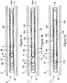
- FIG. 1A there is shown a generally tubular valve assembly generally designated 2 located in a wellbore 4 during deployment of a tubing string (not shown) into the wellbore 4.
- the downhole direction is indicated by arrow 6.
- references to a particular direction or orientation such as “down”, “up”, “upper”, “lower”, “above”, “below”, “side” and the like used throughout the following description apply to the orientation of the valve assembly 2 in use downhole as shown in Figures 1A - 1C and are not intended to be limiting in any way.
- the valve assembly 2 may be utilised in vertical, deviated and/or horizontal wellbores.
- the valve assembly 2 comprises a generally tubular housing 8 defining a housing flow path 9.
- the housing 8 comprises an upper threaded end portion 10 for coupling to a lower threaded end portion of a tubing string (not shown) and a lower threaded end portion 11 for coupling to an upper end portion of a further tubing string (not shown), or a further component, such as a tubing shoe or the like.
- the valve assembly 2 comprises a generally tubular valve sleeve assembly 12 located within the housing 8.
- the valve sleeve assembly 12 further comprises a barrier member 14 that is configurable between a normally-closed position shown in Figures 1A and 1B in which the barrier member 14 prevents fluid flow along the housing flow path 9 and an open position shown in Figure 1C in which fluid flow is permitted along the housing flow path 9.
- valve sleeve assembly 12 is configured for displacement within the housing 8.
- the valve sleeve assembly 12 is biased towards an upper position shown in Figures 1A and 2A within the housing 8 so as to permit filling of the tubing string with fluid from the wellbore 4.
- the valve sleeve assembly 12 is movable towards a lower position shown in Figure 1B within the housing 8 against the bias so as to permit pressurization of fluid within the tubing string for the integrity testing thereof.
- fluid within the tubing string may be depressurized and the barrier member 14 may be opened to permit fluid flow along the housing flow path 9, for example to permit a fluid to flow along the housing flow path 9 to surface.
- the valve sleeve assembly 12 comprises the barrier member 14 and a generally tubular sleeve 28 located within the housing flow path 9.
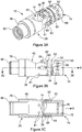
- the barrier member 14 is pivotally connected to the sleeve 28 by a hinge 34.
- the valve sleeve assembly 12 comprises a spring 36 which is configured around the hinge 34 to bias the barrier member 14 in the closed position shown in Figures 3A to 3C .
- the barrier member 14 is also held in the normally-closed position by a shear pin 38.
- the valve sleeve assembly 12 comprises a larger side aperture 40 and a plurality of smaller side apertures 41 formed in a side wall 42 of the sleeve 28 at a position above the barrier member 14.
- the larger side aperture 40 is configured to accommodate the barrier member 14 when the barrier member 14 is configured in the open position as shown in Figure 1C . Both the larger side aperture 40 and smaller side apertures 41 form upper bypass ports.
- the valve sleeve assembly 12 further comprises a plurality of lower bypass ports 50 formed through the side wall 42 of the sleeve 28 at a position below the barrier member 14.
- the bypass ports 50 are arranged around an axis of the valve sleeve assembly 12 with a uniform angular distribution.
- the valve sleeve assembly 12 comprises a flow restrictor ring 52 located around an intermediate portion 53 of the valve sleeve assembly 12 located axially between the lower bypass ports 50 and upper bypass ports formed by the larger side aperture 40 and smaller apertures 41.
- the valve sleeve assembly 12 is configured to provide a gap 54 between an inner surface of the flow restrictor ring 52 and an outer surface of the neck portion. More specifically, valve sleeve assembly 12 comprises a resilient centralising arrangement 55 which biases the flow restrictor ring 52 towards a coaxial alignment with the valve sleeve assembly 12.
- the intermediate portion 53 of the valve sleeve assembly 12 is defined between upper and lower shoulders 56 and 58 respectively formed on an outer surface of the sleeve 28.
- the flow restrictor ring 52 comprises a series of larger notches 60 formed around an upper edge 62 thereof and a series of smaller notches 64 formed around a lower edge 66 thereof.
- the flow restrictor ring 52 and the intermediate portion 53 are configured to permit axial displacement of the flow restrictor ring 52 between a first position shown in Figures 3A to 3C in which the upper edge 62 of the flow restrictor ring 52 engages the upper shoulder 56 of the side wall 42 and a second position (not shown) in which the lower edge 66 of the flow restrictor ring 52 engages the lower shoulder 56 of the side wall 42 according to a flow of fluid around the flow restrictor ring 52.
- the flow restrictor ring 52 and the housing 8 are configured such that an outer surface of the flow restrictor ring 52 engages an inner surface of the housing 8 when the valve sleeve assembly 12 is located within the housing 8.
- the housing 8 and the valve sleeve assembly 12 together define a generally annular recess 67 between an inner surface of the housing 8 and an outer surface of the valve sleeve assembly 12.
- the housing 8 and the valve sleeve assembly 12 are configured to provide a sliding fit for the flow restrictor ring 52 within the recess 67.
- the valve assembly 2 comprises a bias spring 68 that acts between a recess 70 of the housing 8 and a recess 72 formed in a lower end 74 of the valve sleeve assembly 12 to bias the valve sleeve assembly 12 towards an upper position within the housing 8 such that a shoulder 76 of the valve sleeve assembly 12 engages a recess 78 of the housing 8.
- An upper end face 80 of the valve sleeve assembly 12 carries a sealing arrangement comprising a metal to metal seal and a rubber flapper seal for sealing with a further recess 82 of the housing 8.
- valve assembly 2 comprises a sealing arrangement 90 mounted within the housing 8 and configured to form a seal between an inner surface of the housing 8 and an outer surface of the valve sleeve assembly 12.
- the housing 8 and the valve sleeve assembly 12 together define a bypass flow path generally designated 100 which communicates with the housing flow path 9 so as to bypass the barrier member 14 and the sealing arrangement 90 via the lower bypass ports 50 of the valve sleeve assembly 12, the annular recess 67 and the upper bypass ports defined by the larger and smaller side apertures 40, 41 of the valve sleeve assembly 12.
- the gap 54 defined between the flow restrictor ring 52 and the valve sleeve assembly 12 also defines a portion of the bypass flow path 100.
- valve assembly 2 is run into the wellbore 4 as part of a tubing string (not shown) in the initial configuration shown in Figure 1A (and 2A and 2B) with the valve sleeve assembly 12 located at its uppermost position and the sealing arrangement 90 forming a seal around the sleeve 28 of the valve sleeve assembly 12 at a position located downwardly of the lower bypass ports 50.
- the valve assembly 2 moves downwardly through the wellbore fluid such that fluid enters the valve assembly 2 through a lower end thereof and flows through the bypass flow path 100 to fill the tubing string (not shown) located above the valve assembly 2.
- the lower bypass ports 50 are angled to establish rotational flow and a degree of turbulence within the bypass flow path 100 which may assist to prevent blockage from particulate material transported in the fluid.
- tubing connectors such as threaded connectors.
- To facilitate this deployment may be arrested and the fluid within the tubing string located above the valve sleeve assembly 12 pressurized, for example via surface pumps. This results in a downward flow of fluid through the bypass flow path 100 causing the flow restrictor ring 52 to be displaced downwardly until the lower edge 66 of the flow restrictor ring 52 engages the lower shoulder 58 of the sleeve 28 and fluid flow becomes subject to the increased restriction imposed by the smaller notches 64.
- the valve assembly 2 further comprises a generally tubular actuation sleeve 102 slidably mounted within the housing 8.
- the actuation sleeve 102 comprises an annular piston member 104 which extends into an annular recess 106 defined between an outer surface of the actuation sleeve 102 and an inner surface of the housing 8.
- the valve assembly 2 further comprises a burst disc arrangement 108 which is in communication with the recess 106 and one or more shear pins 110 which are configured to hold the actuation sleeve 102 in its lowermost position shown in Figure 1B and Figure 2B with the annular piston member 104 located at a lower end of the recess 106 until it is desired to open the barrier member 14.
- the pressure of fluid in the wellbore 4 is raised to rupture the burst disc 108 to permit pressurised wellbore fluid to flow into the recess 106 and act upon the annular piston member 104 thereby urging the actuation sleeve 102 upwardly towards its uppermost position shown in Figure 1C , engaging the barrier member causing the shear pin 38 to shear and permit the barrier member to be pivoted open.
- the actuation sleeve 102 provides substantially full bore access for fluid and/or equipment through the housing flow path.
- the actuation sleeve 102 has a curved upper end 112 which is configured to first engage the barrier member 14 at a position or at positions opposite the hinge 34 thereby avoiding the application of excessive forces and avoiding damage to the hinge 34.
- valve assembly 2 may comprise any suitable means for actuation of the valve sleeve assembly 12.
- the valve assembly 2 may comprise an electric actuator such as a motor, solenoid, or the like or a hydraulic actuator configured for actuating the valve sleeve assembly 12.
- the valve assembly 2 may comprise any suitable means for actuation of the actuation sleeve 102, for example an electric actuator such as a motor, solenoid, or the like or a variable flow restrictor.
Landscapes
- Life Sciences & Earth Sciences (AREA)
- Engineering & Computer Science (AREA)
- Geology (AREA)
- Mining & Mineral Resources (AREA)
- Physics & Mathematics (AREA)
- Environmental & Geological Engineering (AREA)
- Fluid Mechanics (AREA)
- General Life Sciences & Earth Sciences (AREA)
- Geochemistry & Mineralogy (AREA)
- Lift Valve (AREA)
- Valve Housings (AREA)
- Multiple-Way Valves (AREA)
Claims (15)
- Ventilanordnung (2), welche konfiguriert ist, um mit einem Rohrstrang gekoppelt zu werden, umfassend:ein Gehäuse (8), welches einen Gehäuseströmungsweg (9) zum Kommunizieren mit dem Rohrstrang definiert;ein Sperrglied (14), welches im Gehäuse (8) angeordnet ist und zwischen einer normalerweise geschlossenen Position, in welcher das Sperrglied (14) den Zugang durch den Gehäuseströmungsweg (9) einschränkt, und einer offenen Position konfigurierbar ist, in welcher der Zugang durch den Gehäuseströmungsweg (9) ermöglicht wird;eine Ventilhülsenanordnung (12), welche innerhalb des Gehäuses (8) angeordnet ist, wobei das Gehäuse (8) und die Ventilhülsenanordnung (12) zusammen einen Bypass-Strömungsweg (100) definieren; undeine Bypass-Anordnung, welche in einen offenen Zustand als Reaktion auf eine Strömung in einer Richtung neukonfigurierbar ist, in welcher der Bypass-Strömungsweg (100) mit dem Gehäuseströmungsweg (9) auf gegenüberliegenden Seiten des Sperrglieds (14) kommuniziert, um dem Fluid zu ermöglichen, das Sperrglied (14) zu umgehen und dadurch den Rohrstrang zu füllen, und welche in einen geschlossenen Zustand als Reaktion auf eine Strömung in einer entgegengesetzten Richtung neukonfigurierbar ist, in welcher dem Fluid verhindert wird, das Sperrglied (14) zu umgehen und dadurch eine Druckbeaufschlagung des Rohrstrangs zu ermöglichen.
- Ventilanordnung (2) nach Anspruch 1, wobei die Bypass-Anordnung zu einem offenen Zustand hin vorgespannt ist, um zwischen einem normalerweise offenen Zustand und einem geschlossenen Zustand gegen die Vorspannung konfigurierbar zu sein.
- Ventilanordnung (2) nach Anspruch 2, wobei der Gehäuseströmungsweg radial im Innern des Bypass-Strömungswegs angeordnet ist.
- Ventilanordnung (2) nach einem der vorhergehenden Ansprüche, wobei die Fluidströmung in der einen Richtung die Bypass-Anordnung in einen offenen Zustand drückt und die Fluidströmung in der zweiten Richtung die Bypass-Anordnung in den geschlossenen Zustand drückt.
- Ventilanordnung nach einem der vorhergehenden Ansprüche, wobei die Bypass-Anordnung eine variable Strömungsdrossel in der Form eines Schwimmelements umfasst, das sich in Abhängigkeit der Strömung durch die Bypass-Anordnung bewegt, um die Strömungsdrosselung zu ändern.
- Ventilanordnung (2) nach Anspruch 5, wobei die Strömungsdrossel durch einen Strömungsdrosselring (52) definiert ist, welcher zwischen einer ersten Position, in welcher der Strömungsdrosselring (52) mit einem ersten Merkmal der Ventilanordnung zusammenwirkt, um eine erste Drosselung zu definieren, und einer zweiten Position gleitend gelagert ist, in welcher der Strömungsdrosselring (52) mit einem zweiten Merkmal der Ventilanordnung zusammenwirkt, um eine zweite größere Drosselung zu definieren.
- Ventilanordnung (2) nach Anspruch 6, wobei der Strömungsdrosselring (52) zwischen der ersten und zweiten Position als Reaktion auf die Richtung der Fluidströmung durch die Bypass-Anordnung beweglich ist.
- Ventilanordnung nach einem der vorhergehenden Ansprüche, wobei die Ventilhülsenanordnung (12) konfiguriert ist, um selektiv die Kommunikation zwischen dem Gehäuseströmungsweg (9) und dem Bypass-Strömungsweg (100) zu öffnen und zu schließen, und optional wobei die Ventilhülsenanordnung (12) einen zentralen Strömungsweg definiert, welcher Teil des Gehäuseströmungswegs (9) bildet.
- Ventilanordnung (2) nach Anspruch 8, wobei die Ventilhülsenanordnung (12) eine Strömungsdrossel zum Aufbringen einer Betätigungskraft auf die Ventilhülsenanordnung (12) in Abhängigkeit eines Fluidströmungszustands umfasst, um die Ventilhülsenanordnung (12) neu zu konfigurieren, um die Kommunikation zwischen dem Gehäuseströmungsweg (9) und dem Bypass-Strömungsweg (100) selektiv zu öffnen und zu schließen.
- Ventilanordnung (2) nach Anspruch 8 oder 9, wobei die Ventilanordnung (2) eine Dichtungsanordnung (90) zum Bilden einer oder mehrerer Dichtungen zwischen dem Gehäuse (8) und der Ventilhülsenanordnung (12) umfasst, und optional wobei die Ventilhülsenanordnung (12) gleitend innerhalb der Dichtungsanordnung (90) gelagert ist, sodass eine relative Bewegung zwischen der Ventilhülsenanordnung (12) und der Dichtungsanordnung (90) selektiv die Kommunikation zwischen dem Gehäuseströmungsweg (9) und dem Bypass-Strömungsweg (100) öffnet und schließt.
- Ventilanordnung (2) nach einem der vorhergehenden Ansprüche, umfassend ein Betätigungsglied (102) zum Öffnen des Sperrglieds (14), und optional wobei das Betätigungsglied (102) zum Verschieben innerhalb des Gehäuses (8) relativ zum Sperrglied (14) konfiguriert ist, und wobei eine Endfläche (112) des Betätigungsglieds (102) zum Eingreifen mit dem Sperrglied (14) optional gekrümmt ist.
- Ventilanordnung (2) nach Anspruch 11, wobei das Sperrglied (14) um ein Scharnier (34) schwenkbar ist und eine Endfläche des Betätigungsglieds (102) so konfiguriert ist, dass eine Verschiebung des Betätigungsglieds (102) zum Sperrglied (14) hin veranlasst, dass ein Abschnitt der Endfläche des Betätigungsglieds (102) mit dem Sperrglied (14) an einer Position eingreift, die einer Position des Scharniers (34) gegenüberliegt.
- Ventilanordnung (2) nach Anspruch 11 oder 12, umfassend einen Aktuator zum Betätigen des Betätigungsglieds (102), um das Sperrglied zu öffnen, und wobei das Betätigungsglied optional hydraulisch betätigt ist, optional indem es dem Bohrlochdruck ausgesetzt ist.
- Verfahren zum Einsetzen eines Rohrstrangs in einem Bohrloch (4), welches ein Fluid enthält, umfassend:
Koppeln des Rohrstrangs mit einer Ventilanordnung (2), wobei die Ventilanordnung (2) umfasst:ein Gehäuse (8), welches einen Gehäuseströmungsweg (9) zum Kommunizieren mit dem Rohrstrang definiert;ein Sperrglied (14), welches im Gehäuse (8) angeordnet ist;eine Ventilhülsenanordnung (12), welche innerhalb des Gehäuses (8) angeordnet ist, wobei das Gehäuse (8) und die Ventilhülsenanordnung (12) zusammen einen Bypass-Strömungsweg (100) definieren; undeine Bypass-Anordnung, welche in einen offenen Zustand als Reaktion auf eine Strömung in einer Richtung neukonfigurierbar ist, in welcher der Bypass-Strömungsweg (100) mit dem Gehäuseströmungsweg (9) auf gegenüberliegenden Seiten des Sperrglieds (14) kommuniziert, um dem Fluid zu ermöglichen, das Sperrglied (14) zu umgehen und dadurch den Rohrstrang zu füllen, und welche in einen geschlossenen Zustand als Reaktion auf eine Strömung in einer entgegengesetzten Richtung neukonfigurierbar ist, in welcher dem Fluid verhindert wird, das Sperrglied (14) zu umgehen und dadurch eine Druckbeaufschlagung des Rohrstrangs zu ermöglichen,Konfigurieren des Sperrglieds (14) in einer normalerweise geschlossenen Position, in welcher das Sperrglied (14) den Zugang durch den Gehäuseströmungsweg (9) einschränkt;Konfigurieren der Bypass-Anordnung in einem offenen Zustand, in welchem der Bypass-Strömungsweg (100) mit dem Gehäuseströmungsweg (9) auf gegenüberliegenden Seiten des Sperrglieds (14) kommuniziert;Bewegen des Rohrstrangs einschließlich der Ventilanordnung (2) nach unten innerhalb des Bohrlochs (4), sodass veranlasst wird, dass Fluid vom Bohrloch (4) das Sperrglied (4) über den Bypass-Strömungsweg (100) umgeht, um dadurch den Rohrstrang zu füllen;Konfigurieren der Bypass-Anordnung in einem geschlossenen Zustand, in welchem dem Fluid verhindert wird, das Sperrglied (14) zu umgehen, indem die Betätigungskräfte verwendet werden, die durch die variable Strömungsdrosselung erzeugt werden, um eine Betätigung der Bypass-Anordnung bereitzustellen und diese zwischen dem offenen und dem geschlossenen Zustand neu zu konfigurieren; undDruckbeaufschlagen des Fluids, welches innerhalb des Rohrstrangs enthalten ist. - Verfahren nach Anspruch 14, umfassend das Konfigurieren des Sperrglieds (14) in einem offenen Zustand, um den Zugang durch den Gehäuseströmungsweg zu ermöglichen, und optional umfassend das Druckentlasten des Fluids, welches innerhalb des Rohrstrangs enthalten ist, zwischen dem Schritt des Druckbeaufschlagens des Fluids innerhalb des Rohrstrangs und dem Schritt des Konfigurierens des Sperrglieds (14) in einer offenen Position, um den Zugang durch den Gehäuseströmungsweg (9) zu ermöglichen.
Applications Claiming Priority (2)
| Application Number | Priority Date | Filing Date | Title |
|---|---|---|---|
| GBGB1019499.1A GB201019499D0 (en) | 2010-11-18 | 2010-11-18 | Valve assembly |
| PCT/GB2011/001605 WO2012066282A2 (en) | 2010-11-18 | 2011-11-15 | Valve assembly |
Publications (2)
| Publication Number | Publication Date |
|---|---|
| EP2640929A2 EP2640929A2 (de) | 2013-09-25 |
| EP2640929B1 true EP2640929B1 (de) | 2019-07-17 |
Family
ID=43431614
Family Applications (1)
| Application Number | Title | Priority Date | Filing Date |
|---|---|---|---|
| EP11787929.6A Active EP2640929B1 (de) | 2010-11-18 | 2011-11-15 | Ventilanordnung |
Country Status (6)
| Country | Link |
|---|---|
| US (1) | US9518444B2 (de) |
| EP (1) | EP2640929B1 (de) |
| AU (1) | AU2011330955B2 (de) |
| CA (1) | CA2818307C (de) |
| GB (1) | GB201019499D0 (de) |
| WO (1) | WO2012066282A2 (de) |
Families Citing this family (19)
| Publication number | Priority date | Publication date | Assignee | Title |
|---|---|---|---|---|
| US8931559B2 (en) * | 2012-03-23 | 2015-01-13 | Ncs Oilfield Services Canada, Inc. | Downhole isolation and depressurization tool |
| WO2014025338A1 (en) | 2012-08-07 | 2014-02-13 | Halliburton Energy Services, Inc. | Mechanically adjustable flow control assembly |
| US9260930B2 (en) * | 2012-08-30 | 2016-02-16 | Halliburton Energy Services, Inc. | Pressure testing valve and method of using the same |
| US9650866B2 (en) | 2013-03-07 | 2017-05-16 | Geodynamics, Inc. | Hydraulic delay toe valve system and method |
| US9121247B2 (en) * | 2013-03-07 | 2015-09-01 | Geodynamics, Inc. | Method and apparatus for establishing injection into a cased bore hole using a time delay toe injection apparatus |
| US10066461B2 (en) | 2013-03-07 | 2018-09-04 | Geodynamics, Inc. | Hydraulic delay toe valve system and method |
| US9121252B2 (en) * | 2013-03-07 | 2015-09-01 | Geodynamics, Inc. | Method and apparatus for establishing injection into a cased bore hole using a time delay toe injection apparatus |
| US10138725B2 (en) | 2013-03-07 | 2018-11-27 | Geodynamics, Inc. | Hydraulic delay toe valve system and method |
| US10138709B2 (en) | 2013-03-07 | 2018-11-27 | Geodynamics, Inc. | Hydraulic delay toe valve system and method |
| WO2015174980A1 (en) * | 2014-05-15 | 2015-11-19 | Halliburton Energy Services, Inc. | Downhole fluid valve |
| GB201506496D0 (en) * | 2015-04-16 | 2015-06-03 | Expro North Sea Ltd | Measurement system and methods |
| WO2016209252A1 (en) * | 2015-06-26 | 2016-12-29 | Halliburton Energy Services, Inc. | Systems and methods for controlling mud flow across a down-hole power generation device |
| NO343059B1 (en) * | 2017-07-12 | 2018-10-22 | Vosstech As | Well Tool Device |
| NO343864B1 (en) | 2018-04-25 | 2019-06-24 | Interwell Norway As | Well tool device for opening and closing a fluid bore in a well |
| US11021930B2 (en) | 2019-01-22 | 2021-06-01 | Weatherford Technology Holdings, Llc | Diverter tool and associated methods |
| NO346907B1 (en) * | 2019-12-20 | 2023-02-20 | Interwell Norway As | Valve assembly, production tubing system, production tubing sub and method for installing a production tubing system |
| US11377928B2 (en) | 2020-05-13 | 2022-07-05 | Weatherford Technology Holdings, Llc | Downhole isolation valves with pressure relief |
| AU2020459959B2 (en) * | 2020-07-20 | 2025-12-04 | Halliburton Energy Services, Inc.. | Internally adjustable flow control module |
| NO349429B1 (en) * | 2024-04-04 | 2026-01-19 | Interwell Norway As | Barrier valve device |
Family Cites Families (9)
| Publication number | Priority date | Publication date | Assignee | Title |
|---|---|---|---|---|
| US4100969A (en) * | 1977-03-28 | 1978-07-18 | Schlumberger Technology Corporation | Tubing tester valve apparatus |
| US4415036A (en) | 1982-02-22 | 1983-11-15 | Baker Oil Tools, Inc. | Pressure equalizing flapper type safety valve for subterranean wells |
| US4582140A (en) * | 1984-09-12 | 1986-04-15 | Halliburton Company | Well tool with selective bypass functions |
| US4694903A (en) | 1986-06-20 | 1987-09-22 | Halliburton Company | Flapper type annulus pressure responsive tubing tester valve |
| US5649597A (en) * | 1995-07-14 | 1997-07-22 | Halliburton Company | Differential pressure test/bypass valve and method for using the same |
| US6189618B1 (en) * | 1998-04-20 | 2001-02-20 | Weatherford/Lamb, Inc. | Wellbore wash nozzle system |
| US7063156B2 (en) | 2002-04-16 | 2006-06-20 | Schlumberger Technology Corporation | Tubing fill and testing valve |
| US7299880B2 (en) | 2004-07-16 | 2007-11-27 | Weatherford/Lamb, Inc. | Surge reduction bypass valve |
| BRPI0515491B1 (pt) | 2004-09-20 | 2017-04-18 | Bj Services Co | válvula de segurança, obstruidor de fundo de poço e processo para instalar uma válvula de segurança |
-
2010
- 2010-11-18 GB GBGB1019499.1A patent/GB201019499D0/en not_active Ceased
-
2011
- 2011-11-15 US US13/884,748 patent/US9518444B2/en active Active
- 2011-11-15 WO PCT/GB2011/001605 patent/WO2012066282A2/en not_active Ceased
- 2011-11-15 AU AU2011330955A patent/AU2011330955B2/en active Active
- 2011-11-15 CA CA2818307A patent/CA2818307C/en active Active
- 2011-11-15 EP EP11787929.6A patent/EP2640929B1/de active Active
Non-Patent Citations (1)
| Title |
|---|
| None * |
Also Published As
| Publication number | Publication date |
|---|---|
| US9518444B2 (en) | 2016-12-13 |
| WO2012066282A3 (en) | 2012-08-02 |
| WO2012066282A2 (en) | 2012-05-24 |
| US20130292133A1 (en) | 2013-11-07 |
| AU2011330955A1 (en) | 2013-05-30 |
| CA2818307A1 (en) | 2012-05-24 |
| EP2640929A2 (de) | 2013-09-25 |
| GB201019499D0 (en) | 2010-12-29 |
| CA2818307C (en) | 2019-04-30 |
| AU2011330955B2 (en) | 2016-11-10 |
Similar Documents
| Publication | Publication Date | Title |
|---|---|---|
| EP2640929B1 (de) | Ventilanordnung | |
| US11692414B2 (en) | Well tool device for opening and closing a fluid bore in a well | |
| US9650866B2 (en) | Hydraulic delay toe valve system and method | |
| EP1519005B1 (de) | Produktionsrohrstrang herausnehmbares ventil zum zementieren | |
| US20060169464A1 (en) | Positioning tool with valved fluid diversion path | |
| US10138725B2 (en) | Hydraulic delay toe valve system and method | |
| CA2760107A1 (en) | Sliding sleeve sub and method and apparatus for wellbore fluid treatment | |
| AU2008343302A1 (en) | Ball dropping assembly and technique for use in a well | |
| WO2008067152A2 (en) | Lubricator valve with rotational flip-flap arm | |
| US20210172278A1 (en) | Jettisonable ball seal | |
| NO348311B1 (en) | Downhole Interventionless Tools, Systems, and Methods for Setting Packers | |
| US10066461B2 (en) | Hydraulic delay toe valve system and method | |
| US10138709B2 (en) | Hydraulic delay toe valve system and method | |
| CA2939553A1 (en) | Hydraulic delay toe valve system and method | |
| US20150369009A1 (en) | Hydraulic Delay Toe Valve System and Method | |
| WO2011137112A2 (en) | Downhole barrier device | |
| CA2939576A1 (en) | Hydraulic delay toe valve system and method | |
| US11578557B2 (en) | Reverse stage cementing sub | |
| EP2875205B1 (de) | Druckmittelbetriebenes muldenblockierungswerkzeug | |
| US11566490B2 (en) | Gravel pack service tool used to set a packer | |
| AU2014349180A1 (en) | Gravel pack service tool used to set a packer | |
| RU2806437C1 (ru) | Инструмент и система для заканчивания скважин и способ эксплуатации инструмента для заканчивания скважин | |
| AU2011265358B2 (en) | A subsurface safety valve including safe additive injection |
Legal Events
| Date | Code | Title | Description |
|---|---|---|---|
| PUAI | Public reference made under article 153(3) epc to a published international application that has entered the european phase |
Free format text: ORIGINAL CODE: 0009012 |
|
| 17P | Request for examination filed |
Effective date: 20130426 |
|
| AK | Designated contracting states |
Kind code of ref document: A2 Designated state(s): AL AT BE BG CH CY CZ DE DK EE ES FI FR GB GR HR HU IE IS IT LI LT LU LV MC MK MT NL NO PL PT RO RS SE SI SK SM TR |
|
| DAX | Request for extension of the european patent (deleted) | ||
| 17Q | First examination report despatched |
Effective date: 20140610 |
|
| STAA | Information on the status of an ep patent application or granted ep patent |
Free format text: STATUS: EXAMINATION IS IN PROGRESS |
|
| REG | Reference to a national code |
Ref country code: DE Ref legal event code: R079 Ref document number: 602011060531 Country of ref document: DE Free format text: PREVIOUS MAIN CLASS: E21B0034100000 Ipc: E21B0034000000 |
|
| GRAP | Despatch of communication of intention to grant a patent |
Free format text: ORIGINAL CODE: EPIDOSNIGR1 |
|
| STAA | Information on the status of an ep patent application or granted ep patent |
Free format text: STATUS: GRANT OF PATENT IS INTENDED |
|
| RIC1 | Information provided on ipc code assigned before grant |
Ipc: E21B 34/00 20060101AFI20190312BHEP Ipc: E21B 34/14 20060101ALI20190312BHEP Ipc: E21B 34/10 20060101ALI20190312BHEP |
|
| INTG | Intention to grant announced |
Effective date: 20190404 |
|
| GRAS | Grant fee paid |
Free format text: ORIGINAL CODE: EPIDOSNIGR3 |
|
| GRAA | (expected) grant |
Free format text: ORIGINAL CODE: 0009210 |
|
| STAA | Information on the status of an ep patent application or granted ep patent |
Free format text: STATUS: THE PATENT HAS BEEN GRANTED |
|
| AK | Designated contracting states |
Kind code of ref document: B1 Designated state(s): AL AT BE BG CH CY CZ DE DK EE ES FI FR GB GR HR HU IE IS IT LI LT LU LV MC MK MT NL NO PL PT RO RS SE SI SK SM TR |
|
| REG | Reference to a national code |
Ref country code: GB Ref legal event code: FG4D |
|
| REG | Reference to a national code |
Ref country code: CH Ref legal event code: EP |
|
| REG | Reference to a national code |
Ref country code: IE Ref legal event code: FG4D |
|
| REG | Reference to a national code |
Ref country code: DE Ref legal event code: R096 Ref document number: 602011060531 Country of ref document: DE |
|
| REG | Reference to a national code |
Ref country code: AT Ref legal event code: REF Ref document number: 1155990 Country of ref document: AT Kind code of ref document: T Effective date: 20190815 |
|
| REG | Reference to a national code |
Ref country code: NO Ref legal event code: T2 Effective date: 20190717 |
|
| REG | Reference to a national code |
Ref country code: NL Ref legal event code: MP Effective date: 20190717 |
|
| REG | Reference to a national code |
Ref country code: LT Ref legal event code: MG4D |
|
| REG | Reference to a national code |
Ref country code: AT Ref legal event code: MK05 Ref document number: 1155990 Country of ref document: AT Kind code of ref document: T Effective date: 20190717 |
|
| PG25 | Lapsed in a contracting state [announced via postgrant information from national office to epo] |
Ref country code: PT Free format text: LAPSE BECAUSE OF FAILURE TO SUBMIT A TRANSLATION OF THE DESCRIPTION OR TO PAY THE FEE WITHIN THE PRESCRIBED TIME-LIMIT Effective date: 20191118 Ref country code: HR Free format text: LAPSE BECAUSE OF FAILURE TO SUBMIT A TRANSLATION OF THE DESCRIPTION OR TO PAY THE FEE WITHIN THE PRESCRIBED TIME-LIMIT Effective date: 20190717 Ref country code: LT Free format text: LAPSE BECAUSE OF FAILURE TO SUBMIT A TRANSLATION OF THE DESCRIPTION OR TO PAY THE FEE WITHIN THE PRESCRIBED TIME-LIMIT Effective date: 20190717 Ref country code: SE Free format text: LAPSE BECAUSE OF FAILURE TO SUBMIT A TRANSLATION OF THE DESCRIPTION OR TO PAY THE FEE WITHIN THE PRESCRIBED TIME-LIMIT Effective date: 20190717 Ref country code: NL Free format text: LAPSE BECAUSE OF FAILURE TO SUBMIT A TRANSLATION OF THE DESCRIPTION OR TO PAY THE FEE WITHIN THE PRESCRIBED TIME-LIMIT Effective date: 20190717 Ref country code: BG Free format text: LAPSE BECAUSE OF FAILURE TO SUBMIT A TRANSLATION OF THE DESCRIPTION OR TO PAY THE FEE WITHIN THE PRESCRIBED TIME-LIMIT Effective date: 20191017 Ref country code: FI Free format text: LAPSE BECAUSE OF FAILURE TO SUBMIT A TRANSLATION OF THE DESCRIPTION OR TO PAY THE FEE WITHIN THE PRESCRIBED TIME-LIMIT Effective date: 20190717 Ref country code: AT Free format text: LAPSE BECAUSE OF FAILURE TO SUBMIT A TRANSLATION OF THE DESCRIPTION OR TO PAY THE FEE WITHIN THE PRESCRIBED TIME-LIMIT Effective date: 20190717 |
|
| PG25 | Lapsed in a contracting state [announced via postgrant information from national office to epo] |
Ref country code: IS Free format text: LAPSE BECAUSE OF FAILURE TO SUBMIT A TRANSLATION OF THE DESCRIPTION OR TO PAY THE FEE WITHIN THE PRESCRIBED TIME-LIMIT Effective date: 20191117 Ref country code: RS Free format text: LAPSE BECAUSE OF FAILURE TO SUBMIT A TRANSLATION OF THE DESCRIPTION OR TO PAY THE FEE WITHIN THE PRESCRIBED TIME-LIMIT Effective date: 20190717 Ref country code: LV Free format text: LAPSE BECAUSE OF FAILURE TO SUBMIT A TRANSLATION OF THE DESCRIPTION OR TO PAY THE FEE WITHIN THE PRESCRIBED TIME-LIMIT Effective date: 20190717 Ref country code: AL Free format text: LAPSE BECAUSE OF FAILURE TO SUBMIT A TRANSLATION OF THE DESCRIPTION OR TO PAY THE FEE WITHIN THE PRESCRIBED TIME-LIMIT Effective date: 20190717 Ref country code: GR Free format text: LAPSE BECAUSE OF FAILURE TO SUBMIT A TRANSLATION OF THE DESCRIPTION OR TO PAY THE FEE WITHIN THE PRESCRIBED TIME-LIMIT Effective date: 20191018 Ref country code: ES Free format text: LAPSE BECAUSE OF FAILURE TO SUBMIT A TRANSLATION OF THE DESCRIPTION OR TO PAY THE FEE WITHIN THE PRESCRIBED TIME-LIMIT Effective date: 20190717 |
|
| PG25 | Lapsed in a contracting state [announced via postgrant information from national office to epo] |
Ref country code: TR Free format text: LAPSE BECAUSE OF FAILURE TO SUBMIT A TRANSLATION OF THE DESCRIPTION OR TO PAY THE FEE WITHIN THE PRESCRIBED TIME-LIMIT Effective date: 20190717 |
|
| PG25 | Lapsed in a contracting state [announced via postgrant information from national office to epo] |
Ref country code: DK Free format text: LAPSE BECAUSE OF FAILURE TO SUBMIT A TRANSLATION OF THE DESCRIPTION OR TO PAY THE FEE WITHIN THE PRESCRIBED TIME-LIMIT Effective date: 20190717 Ref country code: PL Free format text: LAPSE BECAUSE OF FAILURE TO SUBMIT A TRANSLATION OF THE DESCRIPTION OR TO PAY THE FEE WITHIN THE PRESCRIBED TIME-LIMIT Effective date: 20190717 Ref country code: RO Free format text: LAPSE BECAUSE OF FAILURE TO SUBMIT A TRANSLATION OF THE DESCRIPTION OR TO PAY THE FEE WITHIN THE PRESCRIBED TIME-LIMIT Effective date: 20190717 Ref country code: IT Free format text: LAPSE BECAUSE OF FAILURE TO SUBMIT A TRANSLATION OF THE DESCRIPTION OR TO PAY THE FEE WITHIN THE PRESCRIBED TIME-LIMIT Effective date: 20190717 Ref country code: EE Free format text: LAPSE BECAUSE OF FAILURE TO SUBMIT A TRANSLATION OF THE DESCRIPTION OR TO PAY THE FEE WITHIN THE PRESCRIBED TIME-LIMIT Effective date: 20190717 |
|
| PG25 | Lapsed in a contracting state [announced via postgrant information from national office to epo] |
Ref country code: SM Free format text: LAPSE BECAUSE OF FAILURE TO SUBMIT A TRANSLATION OF THE DESCRIPTION OR TO PAY THE FEE WITHIN THE PRESCRIBED TIME-LIMIT Effective date: 20190717 Ref country code: IS Free format text: LAPSE BECAUSE OF FAILURE TO SUBMIT A TRANSLATION OF THE DESCRIPTION OR TO PAY THE FEE WITHIN THE PRESCRIBED TIME-LIMIT Effective date: 20200224 Ref country code: CZ Free format text: LAPSE BECAUSE OF FAILURE TO SUBMIT A TRANSLATION OF THE DESCRIPTION OR TO PAY THE FEE WITHIN THE PRESCRIBED TIME-LIMIT Effective date: 20190717 Ref country code: SK Free format text: LAPSE BECAUSE OF FAILURE TO SUBMIT A TRANSLATION OF THE DESCRIPTION OR TO PAY THE FEE WITHIN THE PRESCRIBED TIME-LIMIT Effective date: 20190717 |
|
| REG | Reference to a national code |
Ref country code: DE Ref legal event code: R119 Ref document number: 602011060531 Country of ref document: DE |
|
| REG | Reference to a national code |
Ref country code: CH Ref legal event code: PL |
|
| PLBE | No opposition filed within time limit |
Free format text: ORIGINAL CODE: 0009261 |
|
| STAA | Information on the status of an ep patent application or granted ep patent |
Free format text: STATUS: NO OPPOSITION FILED WITHIN TIME LIMIT |
|
| PG2D | Information on lapse in contracting state deleted |
Ref country code: IS |
|
| PG25 | Lapsed in a contracting state [announced via postgrant information from national office to epo] |
Ref country code: LU Free format text: LAPSE BECAUSE OF NON-PAYMENT OF DUE FEES Effective date: 20191115 Ref country code: MC Free format text: LAPSE BECAUSE OF FAILURE TO SUBMIT A TRANSLATION OF THE DESCRIPTION OR TO PAY THE FEE WITHIN THE PRESCRIBED TIME-LIMIT Effective date: 20190717 Ref country code: LI Free format text: LAPSE BECAUSE OF NON-PAYMENT OF DUE FEES Effective date: 20191130 Ref country code: CH Free format text: LAPSE BECAUSE OF NON-PAYMENT OF DUE FEES Effective date: 20191130 |
|
| 26N | No opposition filed |
Effective date: 20200603 |
|
| REG | Reference to a national code |
Ref country code: BE Ref legal event code: MM Effective date: 20191130 |
|
| PG25 | Lapsed in a contracting state [announced via postgrant information from national office to epo] |
Ref country code: SI Free format text: LAPSE BECAUSE OF FAILURE TO SUBMIT A TRANSLATION OF THE DESCRIPTION OR TO PAY THE FEE WITHIN THE PRESCRIBED TIME-LIMIT Effective date: 20190717 |
|
| PG25 | Lapsed in a contracting state [announced via postgrant information from national office to epo] |
Ref country code: IE Free format text: LAPSE BECAUSE OF NON-PAYMENT OF DUE FEES Effective date: 20191115 Ref country code: DE Free format text: LAPSE BECAUSE OF NON-PAYMENT OF DUE FEES Effective date: 20200603 Ref country code: FR Free format text: LAPSE BECAUSE OF NON-PAYMENT OF DUE FEES Effective date: 20191130 |
|
| PG25 | Lapsed in a contracting state [announced via postgrant information from national office to epo] |
Ref country code: BE Free format text: LAPSE BECAUSE OF NON-PAYMENT OF DUE FEES Effective date: 20191130 |
|
| PG25 | Lapsed in a contracting state [announced via postgrant information from national office to epo] |
Ref country code: CY Free format text: LAPSE BECAUSE OF FAILURE TO SUBMIT A TRANSLATION OF THE DESCRIPTION OR TO PAY THE FEE WITHIN THE PRESCRIBED TIME-LIMIT Effective date: 20190717 |
|
| PG25 | Lapsed in a contracting state [announced via postgrant information from national office to epo] |
Ref country code: MT Free format text: LAPSE BECAUSE OF FAILURE TO SUBMIT A TRANSLATION OF THE DESCRIPTION OR TO PAY THE FEE WITHIN THE PRESCRIBED TIME-LIMIT Effective date: 20190717 Ref country code: HU Free format text: LAPSE BECAUSE OF FAILURE TO SUBMIT A TRANSLATION OF THE DESCRIPTION OR TO PAY THE FEE WITHIN THE PRESCRIBED TIME-LIMIT; INVALID AB INITIO Effective date: 20111115 |
|
| PG25 | Lapsed in a contracting state [announced via postgrant information from national office to epo] |
Ref country code: MK Free format text: LAPSE BECAUSE OF FAILURE TO SUBMIT A TRANSLATION OF THE DESCRIPTION OR TO PAY THE FEE WITHIN THE PRESCRIBED TIME-LIMIT Effective date: 20190717 |
|
| P01 | Opt-out of the competence of the unified patent court (upc) registered |
Effective date: 20230512 |
|
| PGFP | Annual fee paid to national office [announced via postgrant information from national office to epo] |
Ref country code: GB Payment date: 20250925 Year of fee payment: 15 |
|
| PGFP | Annual fee paid to national office [announced via postgrant information from national office to epo] |
Ref country code: NO Payment date: 20251113 Year of fee payment: 15 |