EP2640980B1 - Commande de moteur - Google Patents
Commande de moteur Download PDFInfo
- Publication number
- EP2640980B1 EP2640980B1 EP11788002.1A EP11788002A EP2640980B1 EP 2640980 B1 EP2640980 B1 EP 2640980B1 EP 11788002 A EP11788002 A EP 11788002A EP 2640980 B1 EP2640980 B1 EP 2640980B1
- Authority
- EP
- European Patent Office
- Prior art keywords
- piston
- piston assembly
- motor control
- control system
- sensor
- Prior art date
- Legal status (The legal status is an assumption and is not a legal conclusion. Google has not performed a legal analysis and makes no representation as to the accuracy of the status listed.)
- Active
Links
Images

Classifications
-
- F—MECHANICAL ENGINEERING; LIGHTING; HEATING; WEAPONS; BLASTING
- F15—FLUID-PRESSURE ACTUATORS; HYDRAULICS OR PNEUMATICS IN GENERAL
- F15B—SYSTEMS ACTING BY MEANS OF FLUIDS IN GENERAL; FLUID-PRESSURE ACTUATORS, e.g. SERVOMOTORS; DETAILS OF FLUID-PRESSURE SYSTEMS, NOT OTHERWISE PROVIDED FOR
- F15B15/00—Fluid-actuated devices for displacing a member from one position to another; Gearing associated therewith
- F15B15/20—Other details, e.g. assembly with regulating devices
- F15B15/28—Means for indicating the position, e.g. end of stroke
- F15B15/2815—Position sensing, i.e. means for continuous measurement of position, e.g. LVDT
- F15B15/2861—Position sensing, i.e. means for continuous measurement of position, e.g. LVDT using magnetic means
Definitions
- the present invention is directed to a motor control and, more specifically, to a motor control that is configured to track the position of a piston in a motor.
- a photoelectronic sensor is configured to generate a signal when the piston reaches one end of the piston chamber.
- the signal generated by the photoelectronic sensor is a digital signal that provides only discrete, discontinuous position data when the piston has reached the end of the piston chamber.
- a magnetic hall sensor is disposed on a circumferential wall that defines the piston chamber and a magnet is coupled to the piston.
- the hall sensor functions similarly to the example above, wherein the hall sensor generates a discrete signal when the magnet passes by the hall sensor to determine an instantaneous position of the piston as it passes by the hall sensor. For some applications, such discrete data is sufficient for satisfactory control the motor.
- a motor control system includes a piston chamber and a piston assembly disposed within the piston chamber to move therein between first and second positions.
- a magnet is coupled to the piston assembly to move therewith and a sensor is axially mounted with respect to the piston assembly to generate a continuous output signal corresponding to a position of the magnet relative to the sensor.
- the motor control system also includes a controller for processing the output signal from the sensor to monitor continuously the position of the piston assembly within the piston chamber and for actuating the piston assembly to move in an upstroke toward the first position and in a downstroke toward the second position.
- US 2006/0232268 A1 discloses a position-detecting system for magnetically sensing the position of a first component with respect to a second component.
- the disclosed sensing system may be used in backhoes, tractors or shock damper systems.
- a piston is connected to a rod, which rod is covered with a magnetic layer detectable/readable by a flux sensing apparatus.
- WO 2010/088931 A1 discloses a piston-cylinder assembly with a measuring device disposed inside the cylinder housing. This document is from the field of pneumatic gear shifting systems.
- US 2010/0039103 A1 discloses a magnetic detection system for a movable rod. Several magnets are attached to said rod.
- JP2010-048698 A is directed to a detecting device comprising a magnetic sensor and a LED.
- the sensor is able to detect a position of a movable member comprising a magnet while the LED is turned on depending on the position of the movable member.
- US 5,201,838 relates to a piston-cylinder assembly used in pneumatic prehension pincers for a manipulator robot.
- the piston comprises a magnet, whose position can be determined by radially located magnetic sensors.
- EP 0 589 802 A1 discloses a dispensing device for applying solder onto a substrate used in a semi-conductor technique.
- the device comprises a syringe filled with solder.
- a plunger with a magnet may be lowered by applying pressurized air. If the plunger reaches its bottom most position the syringe has to be replaced.
- a sensor assembly is attached radially with respect to the plunger. The plunger is not movable in an upstroke direction.
- US 5,114,752 A discloses a dispending gun with a needle valve. To the end of the needle a magnet is attached that is movable relative to a coil attached fixedly in a housing of the needle. The coil is connected to a transducer.
- the motor control system includes an end cap housing for mounting on an axial end of a piston chamber and a sensor coupled to the housing.
- the sensor is configured to generate a continuous output signal corresponding to a position of a piston assembly within the piston chamber.
- a controller is coupled to the sensor for processing the output signal from the sensor and monitoring continuously the position of the piston assembly.
- the sensor is a hall sensor that is configured to generate a continuous output signal corresponding to a position of a magnet coupled to the piston assembly.
- the housing further includes an electrical connection for supplying power to electrical components of the controller.
- a motor control system includes a piston chamber, a piston assembly disposed within the piston chamber to move therein between first and second positions, and a sensor axially mounted with respect to the piston assembly to generate an output signal corresponding to a position of the piston assembly relative to the sensor.
- the system also includes a controller for processing the output signal from the sensor to monitor the position and velocity of the piston assembly as the piston assembly is moved between the first and second positions and for actuating the piston assembly to move in an upstroke toward the first position and in a downstroke toward the second position.
- This example may be practiced by a motor control system wherein the controller continuously monitors the position and velocity of the piston assembly.
- a motor control system further comprising an inlet for a fluid and an electrically actuated valve mechanism fluidly coupled to the inlet and controlled by the controller to direct the fluid to move the piston assembly between the first and second positions, and wherein the controller is configured to perform a calibration procedure, which includes moving the piston in the upstroke until the piston is at the first position, storing data relating to the first position, moving the piston in the downstroke until the piston is at the second position, and storing data relating to the second position.
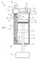
- FIG. 1 illustrates a motor assembly 10 that includes a piston chamber 12 defined by a circumferential sidewall 14 having first and second opposing ends 16, 18, respectively.
- a piston assembly 20 is disposed within the piston chamber 12 and is energized or actuated within the piston chamber to move therein.
- the piston chamber 12 is substantially cylindrical and the piston assembly 20 is configured to move axially within the chamber.
- the piston assembly 20 includes a piston head 22 coupled to a pump shaft 24.
- the first end 16 of the piston chamber 12 is sealed by an end cap housing 26 that can be configured to provide an easily maintained and replaced single housing for all of the control components of the motor assembly 10, as is shown in FIG. 1 and as will be described in more detail hereinafter.
- the second end 18 of the piston chamber is sealed by an end wall 28.
- An opening 30 in the end wall 28 allows the pump shaft 24 to extend therethrough so that the pump shaft can be coupled to a separate system 32 to perform work thereon.
- the separate system 32 can be an adhesive dispensing system and the pump shaft 24 can be coupled thereto to precisely meter and dispense adhesive from the system 32.
- a seal (not shown) may be disposed between the opening 30 in the end wall 28 and the pump shaft 24 to provide a substantially fluid-tight seal, as would be apparent to one of ordinary skill.
- the end cap housing 26 includes a fluid port 34 for coupling to a fluid supply.
- the fluid port 34 functions as a fluid inlet designated generally by the arrow 36.
- the end cap housing 26 also includes an exhaust outlet port 38.
- the fluid port 34 can be coupled to a supply of pressurized air.
- the fluid port 34 may be coupled to a supply of other suitable fluids, such as oil, water, and the like.
- the end cap housing 26 also includes a valve mechanism 40 fluidly coupled to the port 34 for directing a fluid flow to actuate and move the piston assembly 20 within the chamber 12 and to the exhaust outlet 38 to allow fluid to exit the chamber, as will be described in more detail hereinafter.
- the valve mechanism 40 may include one or more electrically actuated valves.
- the valve mechanism 40 includes one or more single or multi-port solenoid valves, such as one or more three-way and four-way solenoid valves, as would be apparent to one of ordinary skill in the art.
- the circumferential sidewall 14 includes a first duct 42 and a second duct 44.
- the first duct 42 includes a first inlet 46 coupled to the valve 40 and a first outlet 48 into the piston chamber 12 at a point generally proximate the first end 16 of the piston chamber.
- the second duct 44 includes a second inlet 50 coupled to the valve 40 and a second outlet 52 into the piston chamber 12 at a point generally proximate the second end 18 of the piston chamber.
- the end cap 26 housing also includes a printed circuit board (“PCB”) 54 that controls the valve 40 to direct a flow of fluid, such as pressurized air, to drive the piston assembly 20 in a downstroke toward the second end 18 of the piston chamber 12 and in an upstroke toward the first end 16 of the piston chamber. More particularly, during the downstroke, the valve 40 opens a fluid flow path represented by an arrow 56 between the port 34 and the first inlet 46 of the first duct 42 to allow the fluid to flow out through the first outlet 48 into the piston chamber 12 and drive the piston assembly 20 toward the second end 18.
- PCB printed circuit board
- the valve 40 may also open a fluid flow path represented by an arrow 58 between the second duct 44 and the exhaust outlet 38 to allow fluid to exit the chamber 12 as the piston assembly is moved toward the second end 18.
- the valve 40 opens a fluid flow path represented by an arrow 60 between the port 34 and the second inlet 50 of the second duct 44 to allow the fluid to flow out through the second outlet 52 into the piston chamber 12 and drive the piston assembly 20 toward the first end 16.
- the valve 40 may also open a fluid flow path represented by an arrow 62 between the first duct 42 and the exhaust outlet 38 to allow fluid to exit the chamber 12 as the piston assembly is moved toward the first end 16.
- An electrical connection 64 may also be disposed on the end cap housing 26 for supplying electrical power to the PCB 54, the valve 40, and/or any other electrical or electromechanical components of the motor assembly 10.
- the motor assembly 10 further includes a sensor 66, such as a hall sensor, capable of generating a continuous, analog signal corresponding to a position of a magnet 68 disposed on the piston assembly 20.
- the magnet 68 may be ring-shaped, disk-shaped, or any other appropriate shape and is disposed on the piston assembly 20 in any known manner, such as by adhesive, screws, clamps, an interference fit, etc.
- the sensor 66 is coupled to the end cap housing 26 and is disposed axially in relation to the movement of the piston assembly 20 within the piston chamber 12.
- the sensor 66 is further coupled to the PCB 54, which processes signals from the sensor to track continuously the position of the magnet 68 and the piston assembly 20 within the piston chamber 12. The placement of the sensor 66 at an axial end of the chamber 12 facilitates the continuous tracking of the magnet 68 and piston assembly 20.
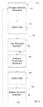
- the PCB 54 and/or some other control system may perform a calibration mode or procedure 80 to collect relevant data before, during, and/or after the motor assembly 10 is utilized in a given application.
- the calibration procedure 80 begins at a block 82, whereby the piston assembly 20 is energized or actuated to move in an upstroke towards the first end 16 of the piston chamber 12, as described above.
- the piston assembly 20 is moved in the upstroke until the piston head 22 stops at a block 84.
- the piston head 22 is mechanically stopped at the block 84, such as when the piston head reaches the end of the chamber 12.
- the PCB 54 collects and stores data, such as the position of the piston assembly 20 when it is stopped at the block 84.
- Position data collected at the block 86 may correspond to an upper limitation of the piston head 20 within the piston chamber 12.
- the piston assembly 20 is moved in the downstroke until the piston head 22 stops at a block 90.
- the piston head can be mechanically stopped at the block 90, such as by reaching the end of the chamber 12.
- the PCB 54 collects and stores data, such as the position of the piston assembly 20 when it is stopped at the block 90.
- the position data collected at the block 92 may correspond to a lower limitation of the piston head 20 within the piston chamber 12.
- FIG. 4 illustrates a manual calibration procedure 110 in which the piston assembly 20 is energized to move in an upstroke movement at block 112 until the top threshold is reached. Data is collected at block 114 during movement to the top threshold.
- the piston assembly is energized to move in a downstroke movement as at block 118 during which data is collected as at block 120 until the piston assembly reaches the bottom threshold as at block 122.
- the data is stored and used as set forth above.
- FIG. 3 illustrates one example of a normal operating mode or procedure 100 during which the piston assembly 20 is energized or actuated to cause the piston assembly to travel between the upper and lower limitations. More particularly, the piston assembly 20 is energized to move in an upstroke at a block 102 until the piston assembly 20 is stopped at a block 104. In one example, the PCB 54 stops the piston assembly 20 at the block 104 utilizing the calibration data, instead of a mechanical stop similar to the blocks 84 and 90. After the block 104, the piston assembly is energized to move in a downstroke at a block 106 until the piston assembly is stopped at a block 108.
- the PCB 54 can stop the piston assembly at the block 108 utilizing the calibration data, instead of a mechanical stop.
- control passes back to the block 102 and the process of driving the piston assembly 20 within the piston chamber 12 is repeated.
- the blocks 104, 108 utilize the calibration data, such as the positions of the piston assembly 20 at the upper and lower limitations, and may stop the piston assembly 20 at any position within the piston chamber 12, such as at the upper and lower limitations or anywhere therebetween.
- the blocks 102-108 energize the piston assembly 20 to travel between the upper and lower limitations minus a small margin to compensate for tolerances and drifts of the motor assembly 10.
- the blocks 104, 108 may stop the piston assembly 20 instantaneously as the piston assembly is transitioned between the upstroke and downstroke or may stop the piston assembly for a longer period of time.
- the sensor 66 can continuously generate position data for the magnet 68 and the piston assembly 20.
- the PCB 54 can use this continuous position data to accurately control actuation of the piston assembly 20 and operation of the motor assembly 10. Further, the continuous tracking of the position of the piston assembly 20 allows the PCB 54 to determine a velocity and acceleration thereof as the assembly moves within the piston chamber 12.
- the velocity and/or acceleration data can be used to check the proper operation of the valve mechanism 40 that directs fluid flow through the first and second ducts 42, 44. For example, a direction of quick stroking based on the velocity and/or acceleration data may indicate one or more fluid flow paths being stuck open.
- the PCB 54 can also use the position data to log strokes or cycles of the piston assembly 20 and provide maintenance reminders and stroke/cycle limiting functions for portions of the motor assembly 10 or the separate system 32. Further, the PCB 54 can use the position data to adjust a stroke length and/or timing of the piston assembly 20 within the piston chamber 12 in applications, such as, but not limited to adhesive pattern control. Another potential benefit is the ability to precisely detect and correct for stalling of the piston assembly 20 mid stroke. Still further, the position data can be used to calculate a flow rate and consumption of a substance, such as an adhesive. Another possible benefit or application is to tie the position data with a melt rate of the adhesive or glue and to control the piston speed and strokes per minute accordingly.
- the PCB 54 can also control the valve 40 to direct a fluid flow, such as pressurized air, through the first and second ducts 42, 44 simultaneously.
- the block 104 controls the transition between the upstroke (block 102) and the downstroke (block 106).
- the PCB 54 can control the valve 40 to begin opening the fluid flow path 56 so that fluid begins to flow into the piston chamber 12 from the first end 16 even as fluid is flowing through the second duct 44 to drive the piston assembly 20 upward.
- the PCB 54 can control the valve 40 to continue opening the fluid flow path 56 as the valve closes the fluid flow path 60 between the port 34 and the second duct 44.
- This control of fluid through both the first and second ducts 42, 44 helps provide a smooth transition between upstrokes and downstrokes and helps compensate for switching times between upstrokes and downstrokes.
- the block 106 controls the transition between the downstroke (block 106) and the upstroke (block 102).
- the PCB 54 can control the valve 40 to begin opening the fluid flow path 60 so that fluid begins to flow into the piston chamber 12 from the second end 18 even as fluid is flowing through the first duct 42 to drive the piston assembly 20 downward.
- the PCB 54 can control the valve 40 to continue opening the fluid flow path 60 as the valve closes the fluid flow path 56 between the port 34 and the first duct 42.
- the motor control disclosed herein is configured to track accurately and continuously a position of a piston within a motor to provide greater precision and reliability in controlling the actuation of the piston.
- the motor control can be used in an adhesive dispensing system to precisely meter and dispense the adhesive.
Landscapes
- Engineering & Computer Science (AREA)
- Physics & Mathematics (AREA)
- Fluid Mechanics (AREA)
- Mechanical Engineering (AREA)
- General Engineering & Computer Science (AREA)
- Reciprocating Pumps (AREA)
- Actuator (AREA)
- Output Control And Ontrol Of Special Type Engine (AREA)
- Reciprocating, Oscillating Or Vibrating Motors (AREA)
- Control Of Positive-Displacement Pumps (AREA)
Claims (14)
- Système de distribution d'adhésif comprenant un système de commande de moteur (10) afin de doser et de distribuer l'adhésif avec précision, ledit système de commande de moteur (10) comprenant:une chambre de piston (12);un ensemble de piston (20) disposé à l'intérieur de la chambre de piston (12) de manière à se déplacer dans celle-ci entre une première et une seconde positions;un aimant (68) couplé à l'ensemble de piston (20) de manière à se déplacer de concert avec celui-ci,caractérisé en ce que le système de commande de moteur (10) comprend en outre:un capteur (66) monté axialement par rapport à l'ensemble de piston (20) afin de générer un signal de sortie continu qui correspond à une position de l'aimant (68) par rapport au capteur (66);un dispositif de commande (54) pour traiter le signal de sortie en provenance du capteur (66) afin de surveiller de façon continue la position de l'ensemble de piston (20) à l'intérieur de la chambre de piston (12) et pour actionner l'ensemble de piston (20) de telle sorte qu'il exécute une course ascendante en direction de la première position et une course descendante en direction de la seconde position;un boîtier faisant couvercle d'extrémité (26) à monter sur une extrémité axiale (16) de la chambre de piston (12);le capteur (66) étant couplé au boîtier, dans lequel le capteur (66) est configuré de manière à générer le signal de sortie continu qui correspond à la position de l'ensemble de piston (20) à l'intérieur de la chambre de piston (12); etle dispositif de commande (54) étant couplé au capteur (66) afin de traiter le signal de sortie en provenance du capteur (66) et de surveiller de façon continue la position de l'ensemble de piston (20).
- Système de commande de moteur (10) selon la revendication 1, comprenant en outre une entrée (36) pour un fluide et un mécanisme de soupape à commande électrique (40) couplé de façon fluidique à l'entrée (36) afin de diriger le fluide de manière à déplacer l'ensemble de piston (20) entre les première et seconde positions.
- Système de commande de moteur (10) selon la revendication 2, dans lequel le mécanisme de soupape (40) comprend un port de sortie (38) pour évacuer un fluide de la chambre de piston (12), un premier chemin d'écoulement de fluide (60), et un second chemin d'écoulement de fluide (56), dans lequel le dispositif de commande (54) est configuré de manière à ouvrir le premier chemin d'écoulement de fluide (60) pendant la course ascendante afin de diriger le fluide de manière à déplacer l'ensemble de piston (20) en direction de la première position, et à ouvrir le second chemin d'écoulement de fluide (56) pendant la course descendante afin de diriger le fluide de manière à déplacer l'ensemble de piston (20) en direction de la seconde position.
- Système de commande de moteur (10) selon la revendication 3, dans lequel le dispositif de commande (54) est configuré de manière à commander les premier et second chemins d'écoulement de fluide (60, 56) afin que tous les deux soient au moins partiellement ouverts lorsque l'ensemble de piston (20) exécute une transition entre la course ascendante et la course descendante.
- Système de commande de moteur (10) selon la revendication 2, dans lequel la soupape est une électrovanne et le fluide est de l'air sous pression.
- Système de commande de moteur (10) selon la revendication 1, dans lequel l'ensemble de piston (20) comprend une tête de piston (22) et un arbre de pompe (24), et dans lequel l'aimant (68) est disposé à proximité de la tête de piston (22) et du capteur (66).
- Système de commande de moteur (10) selon la revendication 6, dans lequel l'arbre de pompe (24) est couplé de manière à entraîner un dispositif de distribution.
- Système de commande de moteur (10) selon la revendication 1, dans lequel le capteur (66) est un capteur à effet Hall.
- Système de commande de moteur (10) selon la revendication 1, dans lequel le dispositif de commande (54) est configuré de manière à exécuter une procédure de calibrage, qui comprend le déplacement du piston (20) dans la course ascendante jusqu'à ce que le piston se trouve dans la première position, le stockage de données relatives à la première position, le déplacement du piston (20) dans la course descendante jusqu'à ce que le piston se trouve dans la seconde position, et le stockage de données relatives à la seconde position.
- Système de commande de moteur (10) selon la revendication 1, dans lequel la chambre de piston (12) est sensiblement cylindrique, et l'ensemble de piston (20) est disposé dans celle-ci de manière à se déplacer axialement entre les première et seconde positions.
- Système de commande de moteur (10) selon la revendication 1, dans lequel le boîtier (26) comporte en outre une entrée (36) pour un fluide et une soupape à commande électrique (40) pour commander un écoulement du fluide.
- Système de commande de moteur (10) selon la revendication 11, dans lequel la soupape comprend une sortie d'échappement (38), un premier chemin d'écoulement de fluide (60) et un second chemin d'écoulement de fluide (56), dans lequel le dispositif de commande (54) est configuré de manière à ouvrir les premier et second chemins d'écoulement de fluide (60, 56) afin de diriger le fluide de manière à déplacer l'ensemble de piston (20) à l'intérieur de la chambre de piston (24).
- Système de commande de moteur (10) selon la revendication 1, dans lequel la soupape (40) est une électrovanne.
- Système de commande de moteur (10) selon la revendication 1, dans lequel le dispositif de commande (54) est conçu de manière à traiter le signal de sortie en provenance du capteur (66) afin de surveiller la position et la vitesse de l'ensemble de piston (20) lorsque l'ensemble de piston (20) est déplacé entre les première et seconde positions et pour actionner l'ensemble de piston (20) de telle sorte qu'il exécute une course ascendante en direction de la première position et une course descendante en direction de la seconde position.
Applications Claiming Priority (2)
| Application Number | Priority Date | Filing Date | Title |
|---|---|---|---|
| US12/947,634 US9909601B2 (en) | 2010-11-16 | 2010-11-16 | Motor control |
| PCT/US2011/060844 WO2012068152A2 (fr) | 2010-11-16 | 2011-11-15 | Commande de moteur |
Publications (2)
| Publication Number | Publication Date |
|---|---|
| EP2640980A2 EP2640980A2 (fr) | 2013-09-25 |
| EP2640980B1 true EP2640980B1 (fr) | 2016-11-09 |
Family
ID=45034206
Family Applications (1)
| Application Number | Title | Priority Date | Filing Date |
|---|---|---|---|
| EP11788002.1A Active EP2640980B1 (fr) | 2010-11-16 | 2011-11-15 | Commande de moteur |
Country Status (7)
| Country | Link |
|---|---|
| US (1) | US9909601B2 (fr) |
| EP (1) | EP2640980B1 (fr) |
| JP (1) | JP6077452B2 (fr) |
| CN (1) | CN103210219B (fr) |
| BR (1) | BR112013006939B1 (fr) |
| CA (1) | CA2812418C (fr) |
| WO (1) | WO2012068152A2 (fr) |
Families Citing this family (13)
| Publication number | Priority date | Publication date | Assignee | Title |
|---|---|---|---|---|
| US10451982B2 (en) * | 2013-01-23 | 2019-10-22 | Nikon Research Corporation Of America | Actuator assembly including magnetic sensor system for vibrationless position feedback |
| US10000007B2 (en) | 2015-06-10 | 2018-06-19 | Milwaukee Electric Tool Corporation | PEX expanding tool |
| US9862137B2 (en) | 2015-04-20 | 2018-01-09 | Milwaukee Electric Tool Corporation | PEX expanding tool |
| DE102016208826A1 (de) | 2015-06-17 | 2016-12-22 | Osakeyhtiö Skf Aktiebolag | Antriebsmechanismus, Pumpenanordnung und Schmiersystem |
| CN204810800U (zh) * | 2015-07-31 | 2015-11-25 | 讯凯国际股份有限公司 | 液体补充装置及液冷系统 |
| US10502642B2 (en) * | 2017-05-17 | 2019-12-10 | General Electric Company | Non-contact magnetostrictive stress sensor with gap compensation field |
| EP3713681B1 (fr) | 2017-11-22 | 2026-01-21 | Illinois Tool Works Inc. | Procede de surveillance du fonctionnement d'un module de soupape dans un systeme de distribution d'adhesif |
| US12092136B2 (en) | 2018-11-09 | 2024-09-17 | Flowserve Pte. Ltd. | Fluid exchange devices and related controls, systems, and methods |
| US12036664B2 (en) * | 2019-11-05 | 2024-07-16 | Nissan North America, Inc. | End effectors for robotic units used to open and close vehicle doors |
| US12059800B2 (en) | 2019-11-05 | 2024-08-13 | Nissan North America, Inc. | End effectors for robotic units used to open and close vehicle doors |
| MX2022005109A (es) | 2019-12-12 | 2022-05-30 | Flowserve Man Co | Dispositivos de intercambio de fluidos y controles, sistemas y metodos relacionados. |
| US12352369B2 (en) * | 2020-04-21 | 2025-07-08 | Phaedrus, Llc | Steam injection valve actuator, system, and method |
| EP3971424A1 (fr) * | 2020-09-18 | 2022-03-23 | ZF CV Systems Europe BV | Actionneur pneumatique comportant un capteur de position magnétique |
Citations (8)
| Publication number | Priority date | Publication date | Assignee | Title |
|---|---|---|---|---|
| WO1988007713A1 (fr) * | 1987-03-27 | 1988-10-06 | Nordson Corporation | Appareil et procede de distribution de materiaux fluides utilisant un signal de reaction de vitesse dependant de la position |
| US5114752A (en) * | 1988-12-12 | 1992-05-19 | Nordson Corporation | Method for gas-aided dispensing of liquid materials |
| US5201838A (en) * | 1989-09-05 | 1993-04-13 | Philippe Roudaut | Position indicator for a piston controlled robot part |
| EP0589802A1 (fr) * | 1992-09-25 | 1994-03-30 | Tenryu Technics Co., Ltd. | Dispensateur |
| US5985357A (en) * | 1997-01-28 | 1999-11-16 | Dainippon Screen Mfg. Co., Ltd. | Treating solution supplying method and apparatus |
| US6334553B1 (en) * | 2000-03-06 | 2002-01-01 | Nordson Corporation | Anti-float plunger for pneumatically actuated syringe |
| EP1327482A2 (fr) * | 2002-01-15 | 2003-07-16 | Creative Automation Company | Pompe |
| US20100258592A1 (en) * | 2009-04-09 | 2010-10-14 | Illinois Tool Works, Inc. | Magnetic drive for dispensing apparatus |
Family Cites Families (54)
| Publication number | Priority date | Publication date | Assignee | Title |
|---|---|---|---|---|
| US2755966A (en) * | 1950-05-01 | 1956-07-24 | Lindars Herman | Apparatus for dispensing measured quantities of liquid materials |
| US4343597A (en) | 1980-04-11 | 1982-08-10 | Facet Enterprises, Inc. | Reciprocating fluid pump having a hall switch |
| US4778353A (en) | 1980-09-25 | 1988-10-18 | Facet Enterprises, Inc. | Hall switch pump |
| JPS5983202U (ja) | 1982-11-26 | 1984-06-05 | 太陽鉄工株式会社 | 切換弁付流体圧シリンダ |
| US4901628A (en) * | 1983-08-11 | 1990-02-20 | General Motors Corporation | Hydraulic actuator having a microwave antenna |
| JPH0329607Y2 (fr) | 1985-04-01 | 1991-06-24 | ||
| DK195886A (da) | 1986-04-29 | 1987-10-30 | Niels Hvilsted | Arbejdscylinder med stempel og med en magnetisk anordning til bestemmelse af en stempelposition |
| US4857842A (en) | 1987-06-03 | 1989-08-15 | Kineret Engineering | Temperature compensated hall effect position sensor |
| JPS6469806A (en) | 1987-09-10 | 1989-03-15 | Ckd Controls | Piston position detecting apparatus of hydraulic cylinder |
| EP0355179B1 (fr) * | 1988-08-18 | 1992-05-06 | Festo KG | Disposition de vérin linéaire |
| DE4108158C2 (de) * | 1991-03-14 | 2002-11-28 | Festo Ag & Co | Linear-Antriebsvorrichtung |
| JP3514474B2 (ja) * | 1991-09-05 | 2004-03-31 | Smc株式会社 | 真空制御装置付シリンダ |
| GB9121367D0 (en) | 1991-10-09 | 1991-11-20 | Emhart Glass Mach Invest | Hall sensor movement detection device |
| US5325063A (en) | 1992-05-11 | 1994-06-28 | Caterpillar Inc. | Linear position sensor with means to eliminate spurians harmonic detections |
| US5275539A (en) | 1992-06-09 | 1994-01-04 | Outboard Marine Corporation | Internal combustion engine oil pump |
| US5325762A (en) | 1992-10-29 | 1994-07-05 | Nordson Corporation | Fluid pressure operated piston engine assembly |
| JPH06222816A (ja) * | 1993-01-21 | 1994-08-12 | Smc Corp | アクチュエータの制御方法および装置 |
| JP2599235Y2 (ja) | 1993-04-02 | 1999-08-30 | 富士通テン株式会社 | 駆動装置 |
| EP0620647A3 (fr) | 1993-04-14 | 1995-09-06 | Namco Controls Corp | Commutateur de proximité magnétique. |
| DE19617347A1 (de) | 1996-04-30 | 1997-11-06 | Weber Hydraulik Gmbh | Kolben-Zylindereinheit |
| US6155806A (en) * | 1998-12-16 | 2000-12-05 | Nordson Corporation | Dual acting piston pump having reduced back flow between strokes |
| US6257118B1 (en) * | 1999-05-17 | 2001-07-10 | Caterpillar Inc. | Method and apparatus for controlling the actuation of a hydraulic cylinder |
| US6510719B2 (en) * | 2000-04-28 | 2003-01-28 | Novartec @ Ag | Pressing tool and pressing process for extruding press fittings |
| DE10049958B4 (de) * | 2000-10-10 | 2004-12-02 | Festo Ag & Co | Fluidtechnische Anordnung sowie Ventilanordnung und Aktuator hierfür |
| US6736611B2 (en) * | 2000-10-23 | 2004-05-18 | Goodrich Corporation | Aircraft fluid delivery device |
| DE10053995A1 (de) | 2000-10-31 | 2002-05-08 | Continental Teves Ag & Co Ohg | In einen Hauptzylinder integrierter Signalgeber mit Hall-Sensor |
| WO2002068828A1 (fr) * | 2001-02-22 | 2002-09-06 | Festo Ag & Co | Cylindre de travail |
| US6607360B2 (en) | 2001-07-17 | 2003-08-19 | Itt Industries Flojet | Constant pressure pump controller system |
| US7051904B2 (en) | 2001-10-29 | 2006-05-30 | Nordson Corporation | Pump with integral filter for a hot melt adhesive system |
| DE10161541B4 (de) | 2001-12-11 | 2005-05-04 | Balluff Gmbh | Sensoranordnung und Funktionseinheit mit Sensoranordnung |
| US6690160B2 (en) | 2002-04-22 | 2004-02-10 | Deere & Company | Position sensing apparatus |
| CN2539019Y (zh) | 2002-04-26 | 2003-03-05 | 无锡市长江液压缸厂 | 一种带有线性位移传感器的高压重型液压缸 |
| AT412672B (de) * | 2002-10-30 | 2005-05-25 | Hoerbiger Kompressortech Hold | Monitor zur überwachung der bewegungsbahn eines hubkolbens |
| US7023199B2 (en) * | 2002-12-31 | 2006-04-04 | Caterpillar Inc. | Position sensing cylinder cap for ease of service and assembly |
| US7021191B2 (en) * | 2003-01-24 | 2006-04-04 | Viking Technologies, L.C. | Accurate fluid operated cylinder positioning system |
| DE10310428A1 (de) | 2003-03-11 | 2004-09-30 | Hydac Technology Gmbh | Kolbenspeicher |
| DE10313676A1 (de) | 2003-03-26 | 2004-10-07 | Imi Norgren-Herion Fluidtronic Gmbh & Co. Kg | Positionsmeßvorrichtung für fluidische Zylinder-Kolben-Anordnungen |
| KR100478986B1 (ko) | 2003-04-03 | 2005-03-31 | 유근형 | 작동 변위 조절기능이 구비된 액츄에이터 |
| US7351288B2 (en) * | 2003-12-22 | 2008-04-01 | Asml Holding N.V. | Shock absorbing fluidic actuator |
| JP4446377B2 (ja) | 2004-04-08 | 2010-04-07 | 株式会社小松製作所 | 変位センサ |
| US7381035B2 (en) | 2004-04-14 | 2008-06-03 | Nordson Corporation | Piston pump with check shaft |
| US7999538B2 (en) | 2004-06-15 | 2011-08-16 | Asa Electronic Industry Co., Ltd. | Device and system for detecting position |
| US7259553B2 (en) | 2005-04-13 | 2007-08-21 | Sri International | System and method of magnetically sensing position of a moving component |
| DE202005006795U1 (de) * | 2005-04-22 | 2005-07-21 | Festo Ag & Co. | Antriebsvorrichtung mit Stellungsregler |
| EP2041438A2 (fr) | 2006-07-06 | 2009-04-01 | The Board of Regents of The University of Texas System | Système et procédé de pompe volumétrique |
| US7587897B2 (en) * | 2007-04-10 | 2009-09-15 | Illinois Tool Works Inc. | Magnetically sequenced pneumatic motor |
| US7603855B2 (en) | 2007-04-10 | 2009-10-20 | Illinois Tool Works Inc. | Valve with magnetic detents |
| US7603854B2 (en) | 2007-04-10 | 2009-10-20 | Illinois Tool Works Inc. | Pneumatically self-regulating valve |
| JP5004048B2 (ja) * | 2007-07-03 | 2012-08-22 | Smc株式会社 | シリンダ装置 |
| US8058867B2 (en) | 2008-08-18 | 2011-11-15 | Deere & Company | System for determining the position of a movable member |
| JP5180737B2 (ja) | 2008-08-22 | 2013-04-10 | 株式会社コガネイ | 位置検出装置およびそれに用いるコントローラ |
| US8453441B2 (en) * | 2008-11-06 | 2013-06-04 | Purdue Research Foundation | System and method for pump-controlled cylinder cushioning |
| US8262367B2 (en) * | 2008-11-26 | 2012-09-11 | National Coupling Company, Inc. | Fault-tolerant chemical injection system for oil and gas wells |
| DE102009007657A1 (de) | 2009-02-05 | 2010-08-12 | Wabco Gmbh | Kolben-Zylinderanordnung mit integrierter Messeinrichtung |
-
2010
- 2010-11-16 US US12/947,634 patent/US9909601B2/en active Active
-
2011
- 2011-11-15 BR BR112013006939-2A patent/BR112013006939B1/pt active IP Right Grant
- 2011-11-15 WO PCT/US2011/060844 patent/WO2012068152A2/fr not_active Ceased
- 2011-11-15 CA CA2812418A patent/CA2812418C/fr active Active
- 2011-11-15 JP JP2013539956A patent/JP6077452B2/ja active Active
- 2011-11-15 EP EP11788002.1A patent/EP2640980B1/fr active Active
- 2011-11-15 CN CN201180053755.2A patent/CN103210219B/zh active Active
Patent Citations (8)
| Publication number | Priority date | Publication date | Assignee | Title |
|---|---|---|---|---|
| WO1988007713A1 (fr) * | 1987-03-27 | 1988-10-06 | Nordson Corporation | Appareil et procede de distribution de materiaux fluides utilisant un signal de reaction de vitesse dependant de la position |
| US5114752A (en) * | 1988-12-12 | 1992-05-19 | Nordson Corporation | Method for gas-aided dispensing of liquid materials |
| US5201838A (en) * | 1989-09-05 | 1993-04-13 | Philippe Roudaut | Position indicator for a piston controlled robot part |
| EP0589802A1 (fr) * | 1992-09-25 | 1994-03-30 | Tenryu Technics Co., Ltd. | Dispensateur |
| US5985357A (en) * | 1997-01-28 | 1999-11-16 | Dainippon Screen Mfg. Co., Ltd. | Treating solution supplying method and apparatus |
| US6334553B1 (en) * | 2000-03-06 | 2002-01-01 | Nordson Corporation | Anti-float plunger for pneumatically actuated syringe |
| EP1327482A2 (fr) * | 2002-01-15 | 2003-07-16 | Creative Automation Company | Pompe |
| US20100258592A1 (en) * | 2009-04-09 | 2010-10-14 | Illinois Tool Works, Inc. | Magnetic drive for dispensing apparatus |
Also Published As
| Publication number | Publication date |
|---|---|
| US20120118136A1 (en) | 2012-05-17 |
| CN103210219A (zh) | 2013-07-17 |
| CN103210219B (zh) | 2016-08-31 |
| BR112013006939A2 (pt) | 2016-07-19 |
| CA2812418C (fr) | 2015-12-22 |
| BR112013006939B1 (pt) | 2021-05-04 |
| WO2012068152A2 (fr) | 2012-05-24 |
| US9909601B2 (en) | 2018-03-06 |
| CA2812418A1 (fr) | 2012-05-24 |
| EP2640980A2 (fr) | 2013-09-25 |
| JP2013543096A (ja) | 2013-11-28 |
| JP6077452B2 (ja) | 2017-02-08 |
| WO2012068152A3 (fr) | 2012-08-02 |
Similar Documents
| Publication | Publication Date | Title |
|---|---|---|
| CA2812418C (fr) | Commande de moteur | |
| EP2273114B1 (fr) | Pompe alternative avec clapet d'aération et piston surveillés électroniquement | |
| EP2732884B1 (fr) | Système et procédé de distribution d'adhésif comprenant une pompe avec diagnostic intégrés | |
| CN102483079B (zh) | 用于在无位置传感器的情况下获取流体系统的至少一个执行件的位置的位置测量装置 | |
| US9158308B2 (en) | Apparatus using electronically-controlled valves | |
| KR101190316B1 (ko) | 배터리 및 솔레노이드 전자식 모니터링을 구비하는전자식으로 모니터되는 에어 밸브를 구비한 왕복 펌프 | |
| CN101761524A (zh) | 用于以电子方式确定阀门机构的与位置相关的磨损状况的方法及气动阀门 | |
| CN120940108A (zh) | 用于流体应用的活塞极限感测 | |
| KR101197406B1 (ko) | 전자식으로 모니터되는 에어 밸브 및 피스톤을 구비한 왕복펌프 | |
| CN1832878A (zh) | 利用致动器测量流体压力的方法和仪器 | |
| EP1061269A3 (fr) | Procédé et dispositif pour la détection de l'opération défectueuse d'un actionneur de positionnement | |
| US10119836B2 (en) | Tact measurement device for actuator and sensor signal detecting device | |
| CN208546374U (zh) | 一种多传感器集成式智能控制比例换向阀 | |
| CN109475886A (zh) | 用于流体涂覆的活塞限位检测和软件控制 | |
| JP7195557B2 (ja) | 液圧駆動装置 | |
| EP1388673A3 (fr) | Dispositif d'actionnement d'une machine à emballage | |
| JP4198115B2 (ja) | サーボ・弁制御装置 | |
| US10302103B2 (en) | Method and device for indication of the position of hydraulically actuated armatures | |
| KR20150122528A (ko) | 유압작동식 리니어 엑츄에이터 제어장치 | |
| MX2008001332A (en) | Reciprocating pump with electronically monitored air valve and piston | |
| CN102384295A (zh) | 部分回转阀门智能控制驱动装置 |
Legal Events
| Date | Code | Title | Description |
|---|---|---|---|
| PUAI | Public reference made under article 153(3) epc to a published international application that has entered the european phase |
Free format text: ORIGINAL CODE: 0009012 |
|
| 17P | Request for examination filed |
Effective date: 20130416 |
|
| AK | Designated contracting states |
Kind code of ref document: A2 Designated state(s): AL AT BE BG CH CY CZ DE DK EE ES FI FR GB GR HR HU IE IS IT LI LT LU LV MC MK MT NL NO PL PT RO RS SE SI SK SM TR |
|
| DAX | Request for extension of the european patent (deleted) | ||
| RAP1 | Party data changed (applicant data changed or rights of an application transferred) |
Owner name: ILLINOIS TOOL WORKS INC. |
|
| 17Q | First examination report despatched |
Effective date: 20140724 |
|
| GRAP | Despatch of communication of intention to grant a patent |
Free format text: ORIGINAL CODE: EPIDOSNIGR1 |
|
| INTG | Intention to grant announced |
Effective date: 20160630 |
|
| GRAS | Grant fee paid |
Free format text: ORIGINAL CODE: EPIDOSNIGR3 |
|
| GRAA | (expected) grant |
Free format text: ORIGINAL CODE: 0009210 |
|
| AK | Designated contracting states |
Kind code of ref document: B1 Designated state(s): AL AT BE BG CH CY CZ DE DK EE ES FI FR GB GR HR HU IE IS IT LI LT LU LV MC MK MT NL NO PL PT RO RS SE SI SK SM TR |
|
| REG | Reference to a national code |
Ref country code: GB Ref legal event code: FG4D |
|
| REG | Reference to a national code |
Ref country code: AT Ref legal event code: REF Ref document number: 844205 Country of ref document: AT Kind code of ref document: T Effective date: 20161115 Ref country code: CH Ref legal event code: EP |
|
| REG | Reference to a national code |
Ref country code: IE Ref legal event code: FG4D |
|
| REG | Reference to a national code |
Ref country code: DE Ref legal event code: R096 Ref document number: 602011032255 Country of ref document: DE |
|
| REG | Reference to a national code |
Ref country code: FR Ref legal event code: PLFP Year of fee payment: 6 |
|
| PG25 | Lapsed in a contracting state [announced via postgrant information from national office to epo] |
Ref country code: LV Free format text: LAPSE BECAUSE OF FAILURE TO SUBMIT A TRANSLATION OF THE DESCRIPTION OR TO PAY THE FEE WITHIN THE PRESCRIBED TIME-LIMIT Effective date: 20161109 |
|
| REG | Reference to a national code |
Ref country code: LT Ref legal event code: MG4D |
|
| REG | Reference to a national code |
Ref country code: NL Ref legal event code: MP Effective date: 20161109 |
|
| REG | Reference to a national code |
Ref country code: AT Ref legal event code: MK05 Ref document number: 844205 Country of ref document: AT Kind code of ref document: T Effective date: 20161109 |
|
| PG25 | Lapsed in a contracting state [announced via postgrant information from national office to epo] |
Ref country code: GR Free format text: LAPSE BECAUSE OF FAILURE TO SUBMIT A TRANSLATION OF THE DESCRIPTION OR TO PAY THE FEE WITHIN THE PRESCRIBED TIME-LIMIT Effective date: 20170210 Ref country code: NL Free format text: LAPSE BECAUSE OF FAILURE TO SUBMIT A TRANSLATION OF THE DESCRIPTION OR TO PAY THE FEE WITHIN THE PRESCRIBED TIME-LIMIT Effective date: 20161109 Ref country code: NO Free format text: LAPSE BECAUSE OF FAILURE TO SUBMIT A TRANSLATION OF THE DESCRIPTION OR TO PAY THE FEE WITHIN THE PRESCRIBED TIME-LIMIT Effective date: 20170209 Ref country code: LT Free format text: LAPSE BECAUSE OF FAILURE TO SUBMIT A TRANSLATION OF THE DESCRIPTION OR TO PAY THE FEE WITHIN THE PRESCRIBED TIME-LIMIT Effective date: 20161109 Ref country code: SE Free format text: LAPSE BECAUSE OF FAILURE TO SUBMIT A TRANSLATION OF THE DESCRIPTION OR TO PAY THE FEE WITHIN THE PRESCRIBED TIME-LIMIT Effective date: 20161109 |
|
| PG25 | Lapsed in a contracting state [announced via postgrant information from national office to epo] |
Ref country code: FI Free format text: LAPSE BECAUSE OF FAILURE TO SUBMIT A TRANSLATION OF THE DESCRIPTION OR TO PAY THE FEE WITHIN THE PRESCRIBED TIME-LIMIT Effective date: 20161109 Ref country code: RS Free format text: LAPSE BECAUSE OF FAILURE TO SUBMIT A TRANSLATION OF THE DESCRIPTION OR TO PAY THE FEE WITHIN THE PRESCRIBED TIME-LIMIT Effective date: 20161109 Ref country code: HR Free format text: LAPSE BECAUSE OF FAILURE TO SUBMIT A TRANSLATION OF THE DESCRIPTION OR TO PAY THE FEE WITHIN THE PRESCRIBED TIME-LIMIT Effective date: 20161109 Ref country code: PL Free format text: LAPSE BECAUSE OF FAILURE TO SUBMIT A TRANSLATION OF THE DESCRIPTION OR TO PAY THE FEE WITHIN THE PRESCRIBED TIME-LIMIT Effective date: 20161109 Ref country code: AT Free format text: LAPSE BECAUSE OF FAILURE TO SUBMIT A TRANSLATION OF THE DESCRIPTION OR TO PAY THE FEE WITHIN THE PRESCRIBED TIME-LIMIT Effective date: 20161109 Ref country code: IS Free format text: LAPSE BECAUSE OF FAILURE TO SUBMIT A TRANSLATION OF THE DESCRIPTION OR TO PAY THE FEE WITHIN THE PRESCRIBED TIME-LIMIT Effective date: 20170309 Ref country code: ES Free format text: LAPSE BECAUSE OF FAILURE TO SUBMIT A TRANSLATION OF THE DESCRIPTION OR TO PAY THE FEE WITHIN THE PRESCRIBED TIME-LIMIT Effective date: 20161109 Ref country code: BE Free format text: LAPSE BECAUSE OF NON-PAYMENT OF DUE FEES Effective date: 20161130 Ref country code: PT Free format text: LAPSE BECAUSE OF FAILURE TO SUBMIT A TRANSLATION OF THE DESCRIPTION OR TO PAY THE FEE WITHIN THE PRESCRIBED TIME-LIMIT Effective date: 20170309 |
|
| REG | Reference to a national code |
Ref country code: CH Ref legal event code: PL |
|
| PG25 | Lapsed in a contracting state [announced via postgrant information from national office to epo] |
Ref country code: LI Free format text: LAPSE BECAUSE OF NON-PAYMENT OF DUE FEES Effective date: 20161130 Ref country code: EE Free format text: LAPSE BECAUSE OF FAILURE TO SUBMIT A TRANSLATION OF THE DESCRIPTION OR TO PAY THE FEE WITHIN THE PRESCRIBED TIME-LIMIT Effective date: 20161109 Ref country code: RO Free format text: LAPSE BECAUSE OF FAILURE TO SUBMIT A TRANSLATION OF THE DESCRIPTION OR TO PAY THE FEE WITHIN THE PRESCRIBED TIME-LIMIT Effective date: 20161109 Ref country code: DK Free format text: LAPSE BECAUSE OF FAILURE TO SUBMIT A TRANSLATION OF THE DESCRIPTION OR TO PAY THE FEE WITHIN THE PRESCRIBED TIME-LIMIT Effective date: 20161109 Ref country code: CZ Free format text: LAPSE BECAUSE OF FAILURE TO SUBMIT A TRANSLATION OF THE DESCRIPTION OR TO PAY THE FEE WITHIN THE PRESCRIBED TIME-LIMIT Effective date: 20161109 Ref country code: CH Free format text: LAPSE BECAUSE OF NON-PAYMENT OF DUE FEES Effective date: 20161130 Ref country code: SK Free format text: LAPSE BECAUSE OF FAILURE TO SUBMIT A TRANSLATION OF THE DESCRIPTION OR TO PAY THE FEE WITHIN THE PRESCRIBED TIME-LIMIT Effective date: 20161109 |
|
| REG | Reference to a national code |
Ref country code: DE Ref legal event code: R097 Ref document number: 602011032255 Country of ref document: DE |
|
| REG | Reference to a national code |
Ref country code: IE Ref legal event code: MM4A |
|
| PG25 | Lapsed in a contracting state [announced via postgrant information from national office to epo] |
Ref country code: BE Free format text: LAPSE BECAUSE OF FAILURE TO SUBMIT A TRANSLATION OF THE DESCRIPTION OR TO PAY THE FEE WITHIN THE PRESCRIBED TIME-LIMIT Effective date: 20161109 Ref country code: SM Free format text: LAPSE BECAUSE OF FAILURE TO SUBMIT A TRANSLATION OF THE DESCRIPTION OR TO PAY THE FEE WITHIN THE PRESCRIBED TIME-LIMIT Effective date: 20161109 Ref country code: BG Free format text: LAPSE BECAUSE OF FAILURE TO SUBMIT A TRANSLATION OF THE DESCRIPTION OR TO PAY THE FEE WITHIN THE PRESCRIBED TIME-LIMIT Effective date: 20170209 Ref country code: IT Free format text: LAPSE BECAUSE OF FAILURE TO SUBMIT A TRANSLATION OF THE DESCRIPTION OR TO PAY THE FEE WITHIN THE PRESCRIBED TIME-LIMIT Effective date: 20161109 |
|
| PLBE | No opposition filed within time limit |
Free format text: ORIGINAL CODE: 0009261 |
|
| STAA | Information on the status of an ep patent application or granted ep patent |
Free format text: STATUS: NO OPPOSITION FILED WITHIN TIME LIMIT |
|
| PG25 | Lapsed in a contracting state [announced via postgrant information from national office to epo] |
Ref country code: MC Free format text: LAPSE BECAUSE OF FAILURE TO SUBMIT A TRANSLATION OF THE DESCRIPTION OR TO PAY THE FEE WITHIN THE PRESCRIBED TIME-LIMIT Effective date: 20161109 Ref country code: LU Free format text: LAPSE BECAUSE OF NON-PAYMENT OF DUE FEES Effective date: 20161130 |
|
| 26N | No opposition filed |
Effective date: 20170810 |
|
| GBPC | Gb: european patent ceased through non-payment of renewal fee |
Effective date: 20170209 |
|
| REG | Reference to a national code |
Ref country code: FR Ref legal event code: PLFP Year of fee payment: 7 |
|
| PG25 | Lapsed in a contracting state [announced via postgrant information from national office to epo] |
Ref country code: SI Free format text: LAPSE BECAUSE OF FAILURE TO SUBMIT A TRANSLATION OF THE DESCRIPTION OR TO PAY THE FEE WITHIN THE PRESCRIBED TIME-LIMIT Effective date: 20161109 Ref country code: IE Free format text: LAPSE BECAUSE OF NON-PAYMENT OF DUE FEES Effective date: 20161115 |
|
| PG25 | Lapsed in a contracting state [announced via postgrant information from national office to epo] |
Ref country code: GB Free format text: LAPSE BECAUSE OF NON-PAYMENT OF DUE FEES Effective date: 20170209 |
|
| PG25 | Lapsed in a contracting state [announced via postgrant information from national office to epo] |
Ref country code: CY Free format text: LAPSE BECAUSE OF FAILURE TO SUBMIT A TRANSLATION OF THE DESCRIPTION OR TO PAY THE FEE WITHIN THE PRESCRIBED TIME-LIMIT Effective date: 20161109 Ref country code: HU Free format text: LAPSE BECAUSE OF FAILURE TO SUBMIT A TRANSLATION OF THE DESCRIPTION OR TO PAY THE FEE WITHIN THE PRESCRIBED TIME-LIMIT; INVALID AB INITIO Effective date: 20111115 |
|
| PG25 | Lapsed in a contracting state [announced via postgrant information from national office to epo] |
Ref country code: MK Free format text: LAPSE BECAUSE OF FAILURE TO SUBMIT A TRANSLATION OF THE DESCRIPTION OR TO PAY THE FEE WITHIN THE PRESCRIBED TIME-LIMIT Effective date: 20161109 |
|
| PG25 | Lapsed in a contracting state [announced via postgrant information from national office to epo] |
Ref country code: MT Free format text: LAPSE BECAUSE OF NON-PAYMENT OF DUE FEES Effective date: 20161115 |
|
| PG25 | Lapsed in a contracting state [announced via postgrant information from national office to epo] |
Ref country code: TR Free format text: LAPSE BECAUSE OF FAILURE TO SUBMIT A TRANSLATION OF THE DESCRIPTION OR TO PAY THE FEE WITHIN THE PRESCRIBED TIME-LIMIT Effective date: 20161109 |
|
| PG25 | Lapsed in a contracting state [announced via postgrant information from national office to epo] |
Ref country code: AL Free format text: LAPSE BECAUSE OF FAILURE TO SUBMIT A TRANSLATION OF THE DESCRIPTION OR TO PAY THE FEE WITHIN THE PRESCRIBED TIME-LIMIT Effective date: 20161109 |
|
| P01 | Opt-out of the competence of the unified patent court (upc) registered |
Effective date: 20230606 |
|
| PGFP | Annual fee paid to national office [announced via postgrant information from national office to epo] |
Ref country code: DE Payment date: 20251128 Year of fee payment: 15 |
|
| PGFP | Annual fee paid to national office [announced via postgrant information from national office to epo] |
Ref country code: FR Payment date: 20251125 Year of fee payment: 15 |