EP2641004B1 - Durchflussmessventil - Google Patents
Durchflussmessventil Download PDFInfo
- Publication number
- EP2641004B1 EP2641004B1 EP10859658.6A EP10859658A EP2641004B1 EP 2641004 B1 EP2641004 B1 EP 2641004B1 EP 10859658 A EP10859658 A EP 10859658A EP 2641004 B1 EP2641004 B1 EP 2641004B1
- Authority
- EP
- European Patent Office
- Prior art keywords
- valve
- flow
- pressure
- metering
- passage
- Prior art date
- Legal status (The legal status is an assumption and is not a legal conclusion. Google has not performed a legal analysis and makes no representation as to the accuracy of the status listed.)
- Active
Links
Images
Classifications
-
- F—MECHANICAL ENGINEERING; LIGHTING; HEATING; WEAPONS; BLASTING
- F16—ENGINEERING ELEMENTS AND UNITS; GENERAL MEASURES FOR PRODUCING AND MAINTAINING EFFECTIVE FUNCTIONING OF MACHINES OR INSTALLATIONS; THERMAL INSULATION IN GENERAL
- F16K—VALVES; TAPS; COCKS; ACTUATING-FLOATS; DEVICES FOR VENTING OR AERATING
- F16K3/00—Gate valves or sliding valves, i.e. cut-off apparatus with closing members having a sliding movement along the seat for opening and closing
- F16K3/02—Gate valves or sliding valves, i.e. cut-off apparatus with closing members having a sliding movement along the seat for opening and closing with flat sealing faces; Packings therefor
- F16K3/0209—Gate valves or sliding valves, i.e. cut-off apparatus with closing members having a sliding movement along the seat for opening and closing with flat sealing faces; Packings therefor the valve having a particular passage, e.g. provided with a filter, throttle or safety device
-
- F—MECHANICAL ENGINEERING; LIGHTING; HEATING; WEAPONS; BLASTING
- F16—ENGINEERING ELEMENTS AND UNITS; GENERAL MEASURES FOR PRODUCING AND MAINTAINING EFFECTIVE FUNCTIONING OF MACHINES OR INSTALLATIONS; THERMAL INSULATION IN GENERAL
- F16K—VALVES; TAPS; COCKS; ACTUATING-FLOATS; DEVICES FOR VENTING OR AERATING
- F16K5/00—Plug valves; Taps or cocks comprising only cut-off apparatus having at least one of the sealing faces shaped as a more or less complete surface of a solid of revolution, the opening and closing movement being predominantly rotary
- F16K5/06—Plug valves; Taps or cocks comprising only cut-off apparatus having at least one of the sealing faces shaped as a more or less complete surface of a solid of revolution, the opening and closing movement being predominantly rotary with plugs having spherical surfaces; Packings therefor
- F16K5/0605—Plug valves; Taps or cocks comprising only cut-off apparatus having at least one of the sealing faces shaped as a more or less complete surface of a solid of revolution, the opening and closing movement being predominantly rotary with plugs having spherical surfaces; Packings therefor with particular plug arrangements, e.g. particular shape or built-in means
-
- G—PHYSICS
- G01—MEASURING; TESTING
- G01F—MEASURING VOLUME, VOLUME FLOW, MASS FLOW OR LIQUID LEVEL; METERING BY VOLUME
- G01F1/00—Measuring the volume flow or mass flow of fluid or fluent solid material wherein the fluid passes through a meter in a continuous flow
- G01F1/05—Measuring the volume flow or mass flow of fluid or fluent solid material wherein the fluid passes through a meter in a continuous flow by using mechanical effects
- G01F1/34—Measuring the volume flow or mass flow of fluid or fluent solid material wherein the fluid passes through a meter in a continuous flow by using mechanical effects by measuring pressure or differential pressure
-
- G—PHYSICS
- G01—MEASURING; TESTING
- G01F—MEASURING VOLUME, VOLUME FLOW, MASS FLOW OR LIQUID LEVEL; METERING BY VOLUME
- G01F1/00—Measuring the volume flow or mass flow of fluid or fluent solid material wherein the fluid passes through a meter in a continuous flow
- G01F1/05—Measuring the volume flow or mass flow of fluid or fluent solid material wherein the fluid passes through a meter in a continuous flow by using mechanical effects
- G01F1/34—Measuring the volume flow or mass flow of fluid or fluent solid material wherein the fluid passes through a meter in a continuous flow by using mechanical effects by measuring pressure or differential pressure
- G01F1/36—Measuring the volume flow or mass flow of fluid or fluent solid material wherein the fluid passes through a meter in a continuous flow by using mechanical effects by measuring pressure or differential pressure the pressure or differential pressure being created by the use of flow constriction
- G01F1/40—Details of construction of the flow constriction devices
-
- G—PHYSICS
- G01—MEASURING; TESTING
- G01F—MEASURING VOLUME, VOLUME FLOW, MASS FLOW OR LIQUID LEVEL; METERING BY VOLUME
- G01F1/00—Measuring the volume flow or mass flow of fluid or fluent solid material wherein the fluid passes through a meter in a continuous flow
- G01F1/05—Measuring the volume flow or mass flow of fluid or fluent solid material wherein the fluid passes through a meter in a continuous flow by using mechanical effects
- G01F1/34—Measuring the volume flow or mass flow of fluid or fluent solid material wherein the fluid passes through a meter in a continuous flow by using mechanical effects by measuring pressure or differential pressure
- G01F1/36—Measuring the volume flow or mass flow of fluid or fluent solid material wherein the fluid passes through a meter in a continuous flow by using mechanical effects by measuring pressure or differential pressure the pressure or differential pressure being created by the use of flow constriction
- G01F1/40—Details of construction of the flow constriction devices
- G01F1/42—Orifices or nozzles
-
- G—PHYSICS
- G01—MEASURING; TESTING
- G01F—MEASURING VOLUME, VOLUME FLOW, MASS FLOW OR LIQUID LEVEL; METERING BY VOLUME
- G01F1/00—Measuring the volume flow or mass flow of fluid or fluent solid material wherein the fluid passes through a meter in a continuous flow
- G01F1/05—Measuring the volume flow or mass flow of fluid or fluent solid material wherein the fluid passes through a meter in a continuous flow by using mechanical effects
- G01F1/34—Measuring the volume flow or mass flow of fluid or fluent solid material wherein the fluid passes through a meter in a continuous flow by using mechanical effects by measuring pressure or differential pressure
- G01F1/36—Measuring the volume flow or mass flow of fluid or fluent solid material wherein the fluid passes through a meter in a continuous flow by using mechanical effects by measuring pressure or differential pressure the pressure or differential pressure being created by the use of flow constriction
- G01F1/40—Details of construction of the flow constriction devices
- G01F1/44—Venturi tubes
Definitions
- the disclosed subject matter relates generally to fluid systems manufacturing and, more particularly, to a flow metering valve.
- volumetric flow rate In the hydrocarbon industry, meters are employed to measure large quantities of fluid, such as oil, that are transferred from one entity to another (e.g., a custody transfer).
- fluid such as oil
- a custody transfer One of the fundamental measurements in multiphase metering is volumetric flow rate.
- volumetric flow rate measurement is achieved by creating a restriction in the flow path and measuring the pressure drop across the restriction.
- a common instrument for creating this measurement is a venturi.
- the piping through which the volumetric flow rate is to be measured is also used to perform mechanical operations.
- a sensor module, or "pig” may be passed through the line.
- the pig may seal to the inside diameter of the piping so that the pressure created propels the module through the piping.
- Such a module cannot pass through a flow metering section sue to the restricted cross-section.
- a well tree i.e., or Christmas tree
- the well tree includes various valves and instrumentation for monitoring the well and controlling flow there from.
- US-A-2344747 discloses a fluid control mechanism comprising a gate comprising openings alignable with a flow passage, the openings having different diameters.
- a valve comprising a housing; a stem supported by the housing; a valve member coupled to the stem; wherein the valve member comprises a gate having a first passage defined therein with a metering flow profile and a second passage defined therein with an unrestricted flow profile, the second passage having a diameter substantially equal to a diameter of a flow passage defined through said housing; wherein the first and second passages are in use selectively alignable with said flow passage; wherein the metering flow profile comprises an unrestricted portion and a restricted portion, and the valve further comprises a first pressure port communicating with the restricted portion; and wherein the valve further comprises at least one sensor communicating with the unrestricted portion and with the restricted portion for detecting the pressure difference across the metering flow profile.
- an apparatus including a well tree having a production bore and a flow metering valve as defined above coupled to the well tree and communicating with the production bore which forms the said flow passage.
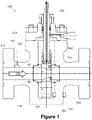
- valve 100 includes a body 110, a bonnet 120, a rising valve stem 130, and a gate 140.
- a valve actuator is not illustrated.
- Various type of manual, motor-operated, or hydraulic operators are known in the art, and may be used in conjunction with the valve 100.
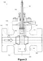
- the gate 140 has two flow passages, an unrestricted passage 150 and a restricted passage 160 having a venturi-type profile.
- the venturi-type profile is a Dall tube profile, which is essentially a shortened venturi tube.
- other types of restricted profiles may be used, such as an orifice plate, a v-cone, a flow mixer, etc.
- Such venturi-type profiles may be collectively referred to as metering profiles.
- the gate 140 may be referred to as a valve member having a first passage defined therein with a metering flow profile and a second passage defined therein with an unrestricted flow profile.
- the conventional parts of the valve 100 such as the packing, stem attachment details, bolts, seals, etc., are not described in detail, as they are known to those of ordinary skill in the art.
- the valve 100 is shown in a seated position. In the seated position, the restricted passage 160 is aligned with the flow path 170. In this position, the valve 100 is in a flow metering position. Sensors 142 and ports 143, 144 are defined in the gate 140 for detecting the pressure across the restricted passage 160. One or more ports 132 may also be defined in the stem 130 for passing an electrical connector to communicate the sensed pressure(s). A differential pressure across the restricted passage 160 may be measured using the sensors 142 and ports 143, 144, to determine the volumetric flow rate. Both absolute pressures may be measured to determine the differential pressure, or a differential pressure sensor may be used. Increased accuracy may be obtained by measuring both differential pressure and the absolute pressure of at least the restricted flow path.
- ports may be provided in the gate 140 or the body 110. It is also contemplated that one or more ports or sensors may be provided in the piping upstream of the valve to measure the unrestricted pressure.
- Those of ordinary skill in the art are familiar with techniques for taking flow measurements across a venturi profile. For example, techniques for measuring flow parameters using a flow restricting device are described in WO2007/129897 , entitled “A METHOD AND APPARATUS FOR TOMOGRAPHIC MULTIPHASE FLOW MEASUREMENTS.”
- valve 100 is shown in a back-seated position. In this position, the unrestricted passage 150 is aligned with the flow path 170. The use of the unrestricted passage 150 allows full flow with minimal pressure losses across the valve 100. Because the unrestricted passage 150 has substantially the same diameter as the attached piping, equipment, such as wire line tools, may be passed through the valve unhindered.
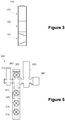
- FIG. 3 a cross-section view of an alternative gate 140' is provided.
- the gate 140 of Figure 1 includes an open position (i.e., unrestricted) and a metering position. In some instances, it may be useful to close the valve entirely. To achieve this capability, the gate 140' includes the unrestricted passage 150, the restricted passage 160, and a solid portion 180 that stops the flow through the valve 100. To accommodate the gate 140', the body 110, bonnet 120, and/or stem 130 dimensions may be modified.
- the solid portion 180 is aligned with the flow path 170 when the gate 140' is in the seated position
- the restricted passage 160 is aligned with the flow path 170 when the gate 140' is in the back-seated position
- the unrestricted passage 150 is aligned with the flow path 170 when the gate 140' is in an intermediate position.
- the open and metering positions are determined by hard travel limits of the valve stem 130.
- the valve 100 may be placed intermediate unrestricted position by providing limits on the actuator or by monitoring a pressure drop across the valve 100. If the unrestricted passage 150 is properly aligned, the pressure drop should be negligible.
- valve 100 described in Figure 1 may also be adapted for an application where a flow metering position and closed position is employed.
- the valve gate would have a restricted passage 160 as in Figures 1 and 2 , and a solid portion 180 as in Figure 3 .
- the unrestricted passage 150 would not be defined in the gate.
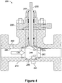
- FIG. 4 is a cross-section of a flow metering ball valve 200 in accordance with another illustrative embodiment not according to the invention.
- the valve 200 includes a body 210, a bonnet 220, a valve stem 230, and a ball 240.
- various type of manual, motor-operated, or hydraulic operators are known in the art, and may be used in conjunction with the valve 200.
- the ball 240 has a restricted passage 260 having a venturi-type profile.
- the ball 240 may be referred to as a valve member having a first passage defined therein with a metering flow profile.
- the conventional parts of the valve 200 such as the packing, stem attachment details, bolts, seals, etc., are not described in detail, as they are known to those of ordinary skill in the art.
- the ball valve 200 is shown in an open position.
- the valve 200 may be placed in a closed position thereby preventing flow by rotating the stem 230 by 90 degrees.
- the restricted passage 260 is aligned with the flow path 270.
- the valve 200 is in a flow metering position.
- Differential and or absolute pressures across the restricted passage 260 may be measured to determine the volumetric flow rate.
- a pressure sensor 275 may be provided in the ball 240 and a port 277 may be formed in the ball to electrically transmit the sensed pressure.
- a sensor 280 and port 282 may also be provided for measuring the unrestricted pressure.
- the particular location of the sensors and ports for measuring the differential and/or absolute pressure(s) may vary.
- ports may be provided in the ball 240 or the body 210. It is also contemplated that one or more ports may be provided in the piping upstream of the valve to measure the unrestricted pressure.
- Pressure sensors may be located inside or outside the pressure boundary of the valve 100, 200.
- the need to port the sensed pressure or route wires through the pressure boundary of the valve 100, 200 may be eliminated by using a non-penetrating cross-pressure-vessel transceiver device within the pressure environment for measuring the restricted pressure, the unrestricted pressure, or both.
- a controller 290 housed outside the pressure environment may communicate with, and can provide power to a sensor 295 within the pressure environment.
- a battery or energy harvesting device may be provided to power the sensor 295.
- non-penetrating sensor 295 and sensors 142 with associated penetrations are illustrated on the same drawing, it is contemplated that both need not be present for measuring the same parameter. However, they may be mixed. For example, a non-penetrating sensor 295 may be used to measure the restricted pressure, while a penetrating sensor 142 may be used to measure the unrestricted pressure.
- a single transceiver device or multiple transceiver devices may be employed as needed for specific applications to transfer power and communication signals.
- Exemplary, non-penetrating interfaces are described in United States Patent Publication No. 2008/0070499 , entitled “MAGNETIC COMMUNICATION THROUGH METAL BARRIERS,” and United States Patent Publication No. 2010/0027379 , entitled “ULTRASONIC THROUGH-WALL COMMUNICATION (UWTC) SYSTEM,”.
- These publications describe communication devices that use a magnetic or ultrasonic signal to communicate and/or provide power through the pressure boundary without actually penetrating the boundary.
- FIG. 5 is a simplified diagram of an illustrative well tree assembly 300 (i.e., or Christmas tree) having a production bore 310 defined therein. Although a surface tree is illustrated, the concepts described herein may also be applied to a subsea installation.
- the well tree assembly 300 includes an upper master valve 320, a lower master valve 330, a flow metering valve 340, and a swab valve 350.
- a flow wing valve 360 and a kill wing valve 370 are coupled to outlets of the well tree assembly 300, and an elbow 380 is coupled to the flow wing valve 360.
- a tree cap 390 is provided above the swab valve 350.
- the flow metering valve 340 is the valve 100 of Figure 1 .
- the unrestricted passage 150 shown in Figure 1 allows well intervention though the well tree 300. If the alternative gate 140' of Figure 2 were used with the valve 340, the lower master valve 330 could be omitted, as its isolation functionality could be performed using the flow metering valve 340.
- the valves 310-370 may be manually operated or actuated ( e.g ., hydraulically, or motor operated) depending on the particular implementation. Moreover, as known to those of ordinary skill in the art, the relative positions of the valves 310-370 may vary, and some valves may be omitted or additional valves may be added.
- the orientation of the tree 300 may also vary (e.g., vertical or horizontal).
Landscapes
- Engineering & Computer Science (AREA)
- General Engineering & Computer Science (AREA)
- Physics & Mathematics (AREA)
- Fluid Mechanics (AREA)
- General Physics & Mathematics (AREA)
- Mechanical Engineering (AREA)
- Indication Of The Valve Opening Or Closing Status (AREA)
- Measuring Volume Flow (AREA)
- Valve Housings (AREA)
- Lift Valve (AREA)
Claims (9)
- Ventil, aufweisend:ein Gehäuse;einen Schaft (130), gestützt durch das Gehäuse;ein an den Schaft gekoppeltes Ventilelement (140);wobei das Ventilelement einen Schieber (140) mit einem ersten Durchlass (160) aufweist, der darin mit einem Messströmungsprofil definiert ist, und mit einem zweiten Durchlass (150), der darin mit einem uneingeschränkten Strömungsprofil definiert ist, wobei der zweite Durchlass einen Durchmesser hat, der im Wesentlichen gleich einem Durchmesser eines Strömungsdurchlasses (170) ist, der durch das Gehäuse definiert ist;wobei der erste und der zweite Durchlass (160, 150) selektiv auf den Strömungsdurchlass (170) ausrichtbar in Verwendung sind;dadurch gekennzeichnet, dassdas Messströmungsprofil einen uneingeschränkten Abschnitt und einen eingeschränkten Abschnitt aufweist, und das Ventil ferner einen zweiten Druckanschluss (144) aufweist, der mit dem eingeschränkten Abschnitt in Verbindung steht, und einen ersten Druckanschluss (143), der mit dem uneingeschränkten Abschnitt in Verbindung steht, wobei das Ventil ferner mindestens einen Sensor (142) aufweist, der mit dem uneingeschränkten Abschnitt und mit dem eingeschränkten Abschnitt mittels des ersten und des zweiten Anschlusses in Verbindung steht, um die Druckdifferenz über das Messströmungsprofil zu erfassen.
- Ventil nach Anspruch 1, wobei der Schieber einen festen Abschnitt (180) aufweist, der größer als ein Durchmesser eines Strömungsdurchlasses (170) ist, der durch das Gehäuse definiert ist.
- Ventil nach Anspruch 1, wobei der Ventilschaft (130) einen steigenden Ventilschaft aufweist.
- Ventil nach Anspruch 1, wobei der zweite Druckanschluss (144) in dem Schieber (140) definiert ist.
- Vorrichtung nach Anspruch 4, wobei der erste Druckanschluss (143) in dem Gehäuse definiert ist.
- Vorrichtung nach Anspruch 4, wobei der mindestens eine Drucksensor ein Differenzdrucksensor ist, der an den ersten und den zweiten Druckanschluss (143, 144) gekoppelt ist.
- Ventil nach Anspruch 1, ferner aufweisend einen Regler (290), der außerhalb einer druckführenden Umschließung des Durchflussmessventils angeordnet ist, wobei der mindestens eine Drucksensor in der druckführenden Umschließung angeordnet ist, und der Regler betriebsfähig ist, um mit dem mindestens einen Drucksensor über die druckführende Umschließung in Verbindung zu stehen, ohne die druckführende Umschließung zu durchdringen.
- Ventil nach einem der vorhergehenden Ansprüche, wobei das Messprofil ein Venturiprofil, ein Dall-Rohrprofil oder eine Messblende aufweist.
- Vorrichtung, aufweisend:eine Bohrloch-Baumstruktur (300) mit einer Produktionsbohrung (310); undein Durchflussmessventil nach einem der vorhergehenden Ansprüche, das mit der Bohrloch-Baumstruktur gekoppelt ist und mit der Produktionsbohrung in Verbindung steht, wobei der Strömungsdurchlass (170) die Produktionsbohrung (310) aufweist.
Applications Claiming Priority (1)
| Application Number | Priority Date | Filing Date | Title |
|---|---|---|---|
| PCT/US2010/056698 WO2012067604A1 (en) | 2010-11-15 | 2010-11-15 | Flow metering valve |
Publications (3)
| Publication Number | Publication Date |
|---|---|
| EP2641004A1 EP2641004A1 (de) | 2013-09-25 |
| EP2641004A4 EP2641004A4 (de) | 2015-01-14 |
| EP2641004B1 true EP2641004B1 (de) | 2017-07-19 |
Family
ID=46084305
Family Applications (1)
| Application Number | Title | Priority Date | Filing Date |
|---|---|---|---|
| EP10859658.6A Active EP2641004B1 (de) | 2010-11-15 | 2010-11-15 | Durchflussmessventil |
Country Status (7)
| Country | Link |
|---|---|
| US (1) | US20140144248A1 (de) |
| EP (1) | EP2641004B1 (de) |
| AU (2) | AU2010364002A1 (de) |
| BR (1) | BR112013011928B1 (de) |
| CA (1) | CA2816960A1 (de) |
| SG (1) | SG190290A1 (de) |
| WO (1) | WO2012067604A1 (de) |
Families Citing this family (12)
| Publication number | Priority date | Publication date | Assignee | Title |
|---|---|---|---|---|
| DE202012102034U1 (de) | 2012-06-04 | 2012-07-12 | Postberg + Co. Druckluft- Controlling Gmbh | Vorrichtung zur Differenzdruckmessung |
| DK2672153T3 (da) * | 2012-06-05 | 2019-11-18 | Delta Systemtechnik Gmbh | Kugleventil |
| GB201213808D0 (en) * | 2012-08-03 | 2012-09-12 | Enston Robert P | Improved pipeline apparatus |
| US9016140B2 (en) | 2012-11-20 | 2015-04-28 | Fluid Handling Llc | Valve having rotatable valve ball with calibrated orifice and coaxial upstream/downstream ports and angled taps to measure upstream/downstream pressures for flow measurement |
| EP2948742B1 (de) * | 2013-01-25 | 2023-10-04 | Fluid Handling LLC. | Drehbare bohrungsplatte für direkte flussmessung |
| US9696187B2 (en) * | 2015-07-01 | 2017-07-04 | Rosemount Aerospace Inc. | Device for measuring total pressure of fluid flow |
| WO2018132114A1 (en) * | 2017-01-16 | 2018-07-19 | Fmc Technologies, Inc. | Integrated flow control and flow measurement apparatus |
| WO2018231233A1 (en) * | 2017-06-15 | 2018-12-20 | Halliburton Energy Services, Inc. | Flow meter apparatus |
| US10612691B2 (en) * | 2018-01-12 | 2020-04-07 | International Business Machines Corporation | Micro electrical mechanical system (MEMS) valve |
| US10823296B2 (en) * | 2018-12-12 | 2020-11-03 | Watts Regulator Co. | Electric mixing valve with dual flowpath metering ball |
| KR102323804B1 (ko) * | 2020-08-06 | 2021-11-09 | (주)다흥 | 자기 부상을 이용한 질량 유량 제어기 |
| CN119491928B (zh) * | 2024-11-01 | 2025-12-05 | 北京金控数据技术股份有限公司 | 一种一体双作用闸阀 |
Family Cites Families (24)
| Publication number | Priority date | Publication date | Assignee | Title |
|---|---|---|---|---|
| US2344747A (en) * | 1940-07-15 | 1944-03-21 | Roland R Crum | Fluid flow control mechanism |
| US2351775A (en) * | 1942-05-15 | 1944-06-20 | Albert F Walter | Gate valve |
| US2601304A (en) * | 1946-09-03 | 1952-06-24 | George S Lanc | Gate valve |
| US2693110A (en) * | 1951-05-07 | 1954-11-02 | Charles E Terrell | Valve embodying fluid measuring means |
| US3063080A (en) * | 1961-01-11 | 1962-11-13 | Panhandle Eastern Pipe Line Co | Combination gate valve and ball launcher and catcher for use in pressure flow lines |
| US3410138A (en) * | 1966-04-15 | 1968-11-12 | Gen Signal Corp | Wide range flow meter |
| US3357491A (en) * | 1967-05-11 | 1967-12-12 | Cameron Iron Works Inc | Christmas tree for wells |
| GB1465953A (en) * | 1974-04-04 | 1977-03-02 | Hopkinsons Ltd | Valves |
| US4501219A (en) * | 1983-04-04 | 1985-02-26 | Nl Industries, Inc. | Tensioner apparatus with emergency limit means |
| US4646624A (en) * | 1984-08-06 | 1987-03-03 | United Technologies Corporation | Differential pressure sensor |
| ATE95305T1 (de) * | 1989-04-03 | 1993-10-15 | Landis & Gyr Business Support | Vorrichtung zur messung des durchflusses und/oder von waermemengen. |
| US5148829A (en) * | 1991-10-25 | 1992-09-22 | Deville Wayne E | Multi-orifice plate and fitting with positioner and differential selector |
| US5588467A (en) * | 1995-03-15 | 1996-12-31 | Crane Manufacturing, Inc. | Orifice fitting |
| DE29702565U1 (de) * | 1997-02-14 | 1998-06-10 | FEV Motorentechnik GmbH & Co. KG, 52078 Aachen | Schnellschaltventil für zwei Betriebsstellungen |
| DE10010716C1 (de) * | 2000-03-04 | 2001-10-31 | Honeywell Ag | Absperrarmatur |
| WO2001066955A2 (en) * | 2000-03-08 | 2001-09-13 | Rosemount Inc. | Bi-directional differential pressure flow sensor |
| US6401747B1 (en) * | 2000-07-13 | 2002-06-11 | Fmc Corporation | Gate valve |
| US7114401B2 (en) * | 2004-08-18 | 2006-10-03 | Baker Hughes Incorporated | Apparatus and methods for abrasive fluid flow meter |
| US7251935B2 (en) * | 2005-08-31 | 2007-08-07 | Caterpillar Inc | Independent metering valve control system and method |
| NO324812B1 (no) | 2006-05-05 | 2007-12-10 | Multi Phase Meters As | Fremgangsmåte og innretning for tomografiske multifasestrømningsmålinger |
| US20080070499A1 (en) | 2006-09-19 | 2008-03-20 | Hydro Technologies, Inc. | Magnetic communication through metal barriers |
| US20100027379A1 (en) | 2006-10-02 | 2010-02-04 | Gary Saulnier | Ultrasonic Through-Wall Communication (UTWC) System |
| US7596996B2 (en) * | 2007-04-19 | 2009-10-06 | Fmc Technologies, Inc. | Christmas tree with internally positioned flowmeter |
| US8302630B2 (en) * | 2008-04-14 | 2012-11-06 | Thunder Rose Enterprises, Inc. | Gate valve with equalizer port |
-
2010
- 2010-11-15 CA CA2816960A patent/CA2816960A1/en not_active Abandoned
- 2010-11-15 EP EP10859658.6A patent/EP2641004B1/de active Active
- 2010-11-15 BR BR112013011928-4A patent/BR112013011928B1/pt active IP Right Grant
- 2010-11-15 US US13/882,769 patent/US20140144248A1/en not_active Abandoned
- 2010-11-15 AU AU2010364002A patent/AU2010364002A1/en not_active Abandoned
- 2010-11-15 WO PCT/US2010/056698 patent/WO2012067604A1/en not_active Ceased
- 2010-11-15 SG SG2013037312A patent/SG190290A1/en unknown
-
2017
- 2017-02-24 AU AU2017201273A patent/AU2017201273B2/en active Active
Non-Patent Citations (1)
| Title |
|---|
| None * |
Also Published As
| Publication number | Publication date |
|---|---|
| EP2641004A1 (de) | 2013-09-25 |
| US20140144248A1 (en) | 2014-05-29 |
| BR112013011928B1 (pt) | 2020-09-29 |
| SG190290A1 (en) | 2013-06-28 |
| AU2017201273B2 (en) | 2017-12-07 |
| EP2641004A4 (de) | 2015-01-14 |
| AU2010364002A1 (en) | 2013-05-30 |
| BR112013011928A2 (pt) | 2016-11-08 |
| CA2816960A1 (en) | 2012-05-24 |
| WO2012067604A1 (en) | 2012-05-24 |
| AU2017201273A1 (en) | 2017-03-16 |
Similar Documents
| Publication | Publication Date | Title |
|---|---|---|
| EP2641004B1 (de) | Durchflussmessventil | |
| US7980305B2 (en) | Ram BOP position sensor | |
| US8316704B2 (en) | Downhole annular measurement system and method | |
| AU2008216253B2 (en) | Ram bop position sensor | |
| US9169709B2 (en) | Spool module | |
| BR112015000374B1 (pt) | sistema integrado de comunicações | |
| US11976534B2 (en) | Wellhead assembly valve systems and methods | |
| EP2085753B1 (de) | Durchflussmessgerät eingesetzt in einem Kugelventil | |
| BR102013020355A2 (pt) | Aparelho, método, e sistema | |
| CA2486348C (en) | Choke valve with temperature transmitter | |
| BRPI1003977A2 (pt) | tubulação instrumentada, sistema de controle de produção, e método para determinar uma contribuição de uma dada zona para a produção de um fluído de um reservatório | |
| US20170130577A1 (en) | True Position Indicator | |
| BRPI1102709B1 (pt) | dispositivo indicador e preventor para vedar um poço | |
| US6923074B2 (en) | Ball valve with flow-rate gauge incorporated directly in the ball | |
| MX2011006017A (es) | Configuraciones y metodos para el control de produccion submarina mejorados. | |
| EP2522997B1 (de) | Überwachung eines Kohlenwasserstoffflüssigkeitsflusses | |
| CN202467827U (zh) | 井下分层直读测试仪 | |
| IT202100026630A1 (it) | Gruppo valvola perfezionato. | |
| US8127792B2 (en) | Pressure equalization system for a bi-directional orifice fitting | |
| US8161825B2 (en) | Orifice fitting with a drainage system | |
| CN101538997A (zh) | 具有集成传感器的井下井阀 | |
| US20110307191A1 (en) | Method of determining position of a valve | |
| CN114562249A (zh) | 一种永置式油井单层流量测试仪结构 | |
| CN201288528Y (zh) | 具有集成传感器的井下井阀及系统 |
Legal Events
| Date | Code | Title | Description |
|---|---|---|---|
| PUAI | Public reference made under article 153(3) epc to a published international application that has entered the european phase |
Free format text: ORIGINAL CODE: 0009012 |
|
| 17P | Request for examination filed |
Effective date: 20130523 |
|
| AK | Designated contracting states |
Kind code of ref document: A1 Designated state(s): AL AT BE BG CH CY CZ DE DK EE ES FI FR GB GR HR HU IE IS IT LI LT LU LV MC MK MT NL NO PL PT RO RS SE SI SK SM TR |
|
| DAX | Request for extension of the european patent (deleted) | ||
| REG | Reference to a national code |
Ref country code: DE Ref legal event code: R079 Ref document number: 602010043813 Country of ref document: DE Free format text: PREVIOUS MAIN CLASS: F16K0043000000 Ipc: F16K0003020000 |
|
| A4 | Supplementary search report drawn up and despatched |
Effective date: 20141212 |
|
| RIC1 | Information provided on ipc code assigned before grant |
Ipc: F16K 5/06 20060101ALI20141208BHEP Ipc: F16K 3/02 20060101AFI20141208BHEP |
|
| GRAP | Despatch of communication of intention to grant a patent |
Free format text: ORIGINAL CODE: EPIDOSNIGR1 |
|
| INTG | Intention to grant announced |
Effective date: 20170216 |
|
| GRAS | Grant fee paid |
Free format text: ORIGINAL CODE: EPIDOSNIGR3 |
|
| GRAA | (expected) grant |
Free format text: ORIGINAL CODE: 0009210 |
|
| AK | Designated contracting states |
Kind code of ref document: B1 Designated state(s): AL AT BE BG CH CY CZ DE DK EE ES FI FR GB GR HR HU IE IS IT LI LT LU LV MC MK MT NL NO PL PT RO RS SE SI SK SM TR |
|
| REG | Reference to a national code |
Ref country code: GB Ref legal event code: FG4D |
|
| REG | Reference to a national code |
Ref country code: CH Ref legal event code: EP |
|
| REG | Reference to a national code |
Ref country code: IE Ref legal event code: FG4D |
|
| REG | Reference to a national code |
Ref country code: AT Ref legal event code: REF Ref document number: 910719 Country of ref document: AT Kind code of ref document: T Effective date: 20170815 |
|
| REG | Reference to a national code |
Ref country code: DE Ref legal event code: R096 Ref document number: 602010043813 Country of ref document: DE |
|
| REG | Reference to a national code |
Ref country code: NO Ref legal event code: T2 Effective date: 20170719 |
|
| REG | Reference to a national code |
Ref country code: NL Ref legal event code: MP Effective date: 20170719 |
|
| REG | Reference to a national code |
Ref country code: LT Ref legal event code: MG4D |
|
| REG | Reference to a national code |
Ref country code: AT Ref legal event code: MK05 Ref document number: 910719 Country of ref document: AT Kind code of ref document: T Effective date: 20170719 |
|
| PG25 | Lapsed in a contracting state [announced via postgrant information from national office to epo] |
Ref country code: HR Free format text: LAPSE BECAUSE OF FAILURE TO SUBMIT A TRANSLATION OF THE DESCRIPTION OR TO PAY THE FEE WITHIN THE PRESCRIBED TIME-LIMIT Effective date: 20170719 Ref country code: AT Free format text: LAPSE BECAUSE OF FAILURE TO SUBMIT A TRANSLATION OF THE DESCRIPTION OR TO PAY THE FEE WITHIN THE PRESCRIBED TIME-LIMIT Effective date: 20170719 Ref country code: FI Free format text: LAPSE BECAUSE OF FAILURE TO SUBMIT A TRANSLATION OF THE DESCRIPTION OR TO PAY THE FEE WITHIN THE PRESCRIBED TIME-LIMIT Effective date: 20170719 Ref country code: SE Free format text: LAPSE BECAUSE OF FAILURE TO SUBMIT A TRANSLATION OF THE DESCRIPTION OR TO PAY THE FEE WITHIN THE PRESCRIBED TIME-LIMIT Effective date: 20170719 Ref country code: NL Free format text: LAPSE BECAUSE OF FAILURE TO SUBMIT A TRANSLATION OF THE DESCRIPTION OR TO PAY THE FEE WITHIN THE PRESCRIBED TIME-LIMIT Effective date: 20170719 Ref country code: LT Free format text: LAPSE BECAUSE OF FAILURE TO SUBMIT A TRANSLATION OF THE DESCRIPTION OR TO PAY THE FEE WITHIN THE PRESCRIBED TIME-LIMIT Effective date: 20170719 |
|
| PG25 | Lapsed in a contracting state [announced via postgrant information from national office to epo] |
Ref country code: GR Free format text: LAPSE BECAUSE OF FAILURE TO SUBMIT A TRANSLATION OF THE DESCRIPTION OR TO PAY THE FEE WITHIN THE PRESCRIBED TIME-LIMIT Effective date: 20171020 Ref country code: IS Free format text: LAPSE BECAUSE OF FAILURE TO SUBMIT A TRANSLATION OF THE DESCRIPTION OR TO PAY THE FEE WITHIN THE PRESCRIBED TIME-LIMIT Effective date: 20171119 Ref country code: PL Free format text: LAPSE BECAUSE OF FAILURE TO SUBMIT A TRANSLATION OF THE DESCRIPTION OR TO PAY THE FEE WITHIN THE PRESCRIBED TIME-LIMIT Effective date: 20170719 Ref country code: BG Free format text: LAPSE BECAUSE OF FAILURE TO SUBMIT A TRANSLATION OF THE DESCRIPTION OR TO PAY THE FEE WITHIN THE PRESCRIBED TIME-LIMIT Effective date: 20171019 Ref country code: RS Free format text: LAPSE BECAUSE OF FAILURE TO SUBMIT A TRANSLATION OF THE DESCRIPTION OR TO PAY THE FEE WITHIN THE PRESCRIBED TIME-LIMIT Effective date: 20170719 Ref country code: ES Free format text: LAPSE BECAUSE OF FAILURE TO SUBMIT A TRANSLATION OF THE DESCRIPTION OR TO PAY THE FEE WITHIN THE PRESCRIBED TIME-LIMIT Effective date: 20170719 Ref country code: LV Free format text: LAPSE BECAUSE OF FAILURE TO SUBMIT A TRANSLATION OF THE DESCRIPTION OR TO PAY THE FEE WITHIN THE PRESCRIBED TIME-LIMIT Effective date: 20170719 |
|
| REG | Reference to a national code |
Ref country code: DE Ref legal event code: R097 Ref document number: 602010043813 Country of ref document: DE |
|
| PG25 | Lapsed in a contracting state [announced via postgrant information from national office to epo] |
Ref country code: RO Free format text: LAPSE BECAUSE OF FAILURE TO SUBMIT A TRANSLATION OF THE DESCRIPTION OR TO PAY THE FEE WITHIN THE PRESCRIBED TIME-LIMIT Effective date: 20170719 Ref country code: DK Free format text: LAPSE BECAUSE OF FAILURE TO SUBMIT A TRANSLATION OF THE DESCRIPTION OR TO PAY THE FEE WITHIN THE PRESCRIBED TIME-LIMIT Effective date: 20170719 Ref country code: CZ Free format text: LAPSE BECAUSE OF FAILURE TO SUBMIT A TRANSLATION OF THE DESCRIPTION OR TO PAY THE FEE WITHIN THE PRESCRIBED TIME-LIMIT Effective date: 20170719 |
|
| PLBE | No opposition filed within time limit |
Free format text: ORIGINAL CODE: 0009261 |
|
| STAA | Information on the status of an ep patent application or granted ep patent |
Free format text: STATUS: NO OPPOSITION FILED WITHIN TIME LIMIT |
|
| PG25 | Lapsed in a contracting state [announced via postgrant information from national office to epo] |
Ref country code: SK Free format text: LAPSE BECAUSE OF FAILURE TO SUBMIT A TRANSLATION OF THE DESCRIPTION OR TO PAY THE FEE WITHIN THE PRESCRIBED TIME-LIMIT Effective date: 20170719 Ref country code: SM Free format text: LAPSE BECAUSE OF FAILURE TO SUBMIT A TRANSLATION OF THE DESCRIPTION OR TO PAY THE FEE WITHIN THE PRESCRIBED TIME-LIMIT Effective date: 20170719 Ref country code: IT Free format text: LAPSE BECAUSE OF FAILURE TO SUBMIT A TRANSLATION OF THE DESCRIPTION OR TO PAY THE FEE WITHIN THE PRESCRIBED TIME-LIMIT Effective date: 20170719 Ref country code: EE Free format text: LAPSE BECAUSE OF FAILURE TO SUBMIT A TRANSLATION OF THE DESCRIPTION OR TO PAY THE FEE WITHIN THE PRESCRIBED TIME-LIMIT Effective date: 20170719 |
|
| REG | Reference to a national code |
Ref country code: DE Ref legal event code: R119 Ref document number: 602010043813 Country of ref document: DE |
|
| 26N | No opposition filed |
Effective date: 20180420 |
|
| PG25 | Lapsed in a contracting state [announced via postgrant information from national office to epo] |
Ref country code: MC Free format text: LAPSE BECAUSE OF FAILURE TO SUBMIT A TRANSLATION OF THE DESCRIPTION OR TO PAY THE FEE WITHIN THE PRESCRIBED TIME-LIMIT Effective date: 20170719 |
|
| PG25 | Lapsed in a contracting state [announced via postgrant information from national office to epo] |
Ref country code: LI Free format text: LAPSE BECAUSE OF NON-PAYMENT OF DUE FEES Effective date: 20171130 Ref country code: CH Free format text: LAPSE BECAUSE OF NON-PAYMENT OF DUE FEES Effective date: 20171130 |
|
| PG25 | Lapsed in a contracting state [announced via postgrant information from national office to epo] |
Ref country code: SI Free format text: LAPSE BECAUSE OF FAILURE TO SUBMIT A TRANSLATION OF THE DESCRIPTION OR TO PAY THE FEE WITHIN THE PRESCRIBED TIME-LIMIT Effective date: 20170719 Ref country code: LU Free format text: LAPSE BECAUSE OF NON-PAYMENT OF DUE FEES Effective date: 20171115 |
|
| REG | Reference to a national code |
Ref country code: FR Ref legal event code: ST Effective date: 20180731 Ref country code: BE Ref legal event code: MM Effective date: 20171130 |
|
| REG | Reference to a national code |
Ref country code: IE Ref legal event code: MM4A |
|
| PG25 | Lapsed in a contracting state [announced via postgrant information from national office to epo] |
Ref country code: MT Free format text: LAPSE BECAUSE OF NON-PAYMENT OF DUE FEES Effective date: 20171115 |
|
| PG25 | Lapsed in a contracting state [announced via postgrant information from national office to epo] |
Ref country code: DE Free format text: LAPSE BECAUSE OF NON-PAYMENT OF DUE FEES Effective date: 20180602 Ref country code: FR Free format text: LAPSE BECAUSE OF NON-PAYMENT OF DUE FEES Effective date: 20171130 Ref country code: IE Free format text: LAPSE BECAUSE OF NON-PAYMENT OF DUE FEES Effective date: 20171115 |
|
| PG25 | Lapsed in a contracting state [announced via postgrant information from national office to epo] |
Ref country code: BE Free format text: LAPSE BECAUSE OF NON-PAYMENT OF DUE FEES Effective date: 20171130 |
|
| PG25 | Lapsed in a contracting state [announced via postgrant information from national office to epo] |
Ref country code: HU Free format text: LAPSE BECAUSE OF FAILURE TO SUBMIT A TRANSLATION OF THE DESCRIPTION OR TO PAY THE FEE WITHIN THE PRESCRIBED TIME-LIMIT; INVALID AB INITIO Effective date: 20101115 |
|
| PG25 | Lapsed in a contracting state [announced via postgrant information from national office to epo] |
Ref country code: CY Free format text: LAPSE BECAUSE OF NON-PAYMENT OF DUE FEES Effective date: 20170719 |
|
| PG25 | Lapsed in a contracting state [announced via postgrant information from national office to epo] |
Ref country code: MK Free format text: LAPSE BECAUSE OF FAILURE TO SUBMIT A TRANSLATION OF THE DESCRIPTION OR TO PAY THE FEE WITHIN THE PRESCRIBED TIME-LIMIT Effective date: 20170719 |
|
| PG25 | Lapsed in a contracting state [announced via postgrant information from national office to epo] |
Ref country code: TR Free format text: LAPSE BECAUSE OF FAILURE TO SUBMIT A TRANSLATION OF THE DESCRIPTION OR TO PAY THE FEE WITHIN THE PRESCRIBED TIME-LIMIT Effective date: 20170719 |
|
| PG25 | Lapsed in a contracting state [announced via postgrant information from national office to epo] |
Ref country code: PT Free format text: LAPSE BECAUSE OF FAILURE TO SUBMIT A TRANSLATION OF THE DESCRIPTION OR TO PAY THE FEE WITHIN THE PRESCRIBED TIME-LIMIT Effective date: 20170719 |
|
| PG25 | Lapsed in a contracting state [announced via postgrant information from national office to epo] |
Ref country code: AL Free format text: LAPSE BECAUSE OF FAILURE TO SUBMIT A TRANSLATION OF THE DESCRIPTION OR TO PAY THE FEE WITHIN THE PRESCRIBED TIME-LIMIT Effective date: 20170719 |
|
| PGFP | Annual fee paid to national office [announced via postgrant information from national office to epo] |
Ref country code: GB Payment date: 20251126 Year of fee payment: 16 |
|
| PGFP | Annual fee paid to national office [announced via postgrant information from national office to epo] |
Ref country code: NO Payment date: 20251028 Year of fee payment: 16 |