EP2641099B1 - Système de surveillance de la fatigue d'un câble et son procédé - Google Patents
Système de surveillance de la fatigue d'un câble et son procédé Download PDFInfo
- Publication number
- EP2641099B1 EP2641099B1 EP10859407.8A EP10859407A EP2641099B1 EP 2641099 B1 EP2641099 B1 EP 2641099B1 EP 10859407 A EP10859407 A EP 10859407A EP 2641099 B1 EP2641099 B1 EP 2641099B1
- Authority
- EP
- European Patent Office
- Prior art keywords
- cable
- electrical signal
- test electrical
- frequency
- test
- Prior art date
- Legal status (The legal status is an assumption and is not a legal conclusion. Google has not performed a legal analysis and makes no representation as to the accuracy of the status listed.)
- Active
Links
Images


Classifications
-
- G—PHYSICS
- G01—MEASURING; TESTING
- G01N—INVESTIGATING OR ANALYSING MATERIALS BY DETERMINING THEIR CHEMICAL OR PHYSICAL PROPERTIES
- G01N3/00—Investigating strength properties of solid materials by application of mechanical stress
- G01N3/08—Investigating strength properties of solid materials by application of mechanical stress by applying steady tensile or compressive forces
-
- G—PHYSICS
- G01—MEASURING; TESTING
- G01R—MEASURING ELECTRIC VARIABLES; MEASURING MAGNETIC VARIABLES
- G01R31/00—Arrangements for testing electric properties; Arrangements for locating electric faults; Arrangements for electrical testing characterised by what is being tested not provided for elsewhere
- G01R31/50—Testing of electric apparatus, lines, cables or components for short-circuits, continuity, leakage current or incorrect line connections
- G01R31/58—Testing of lines, cables or conductors
-
- B—PERFORMING OPERATIONS; TRANSPORTING
- B60—VEHICLES IN GENERAL
- B60L—PROPULSION OF ELECTRICALLY-PROPELLED VEHICLES; SUPPLYING ELECTRIC POWER FOR AUXILIARY EQUIPMENT OF ELECTRICALLY-PROPELLED VEHICLES; ELECTRODYNAMIC BRAKE SYSTEMS FOR VEHICLES IN GENERAL; MAGNETIC SUSPENSION OR LEVITATION FOR VEHICLES; MONITORING OPERATING VARIABLES OF ELECTRICALLY-PROPELLED VEHICLES; ELECTRIC SAFETY DEVICES FOR ELECTRICALLY-PROPELLED VEHICLES
- B60L5/00—Current collectors for power supply lines of electrically-propelled vehicles
-
- G—PHYSICS
- G01—MEASURING; TESTING
- G01M—TESTING STATIC OR DYNAMIC BALANCE OF MACHINES OR STRUCTURES; TESTING OF STRUCTURES OR APPARATUS, NOT OTHERWISE PROVIDED FOR
- G01M13/00—Testing of machine parts
-
- G—PHYSICS
- G01—MEASURING; TESTING
- G01R—MEASURING ELECTRIC VARIABLES; MEASURING MAGNETIC VARIABLES
- G01R31/00—Arrangements for testing electric properties; Arrangements for locating electric faults; Arrangements for electrical testing characterised by what is being tested not provided for elsewhere
- G01R31/08—Locating faults in cables, transmission lines, or networks
- G01R31/11—Locating faults in cables, transmission lines, or networks using pulse reflection methods
-
- G—PHYSICS
- G05—CONTROLLING; REGULATING
- G05B—CONTROL OR REGULATING SYSTEMS IN GENERAL; FUNCTIONAL ELEMENTS OF SUCH SYSTEMS; MONITORING OR TESTING ARRANGEMENTS FOR SUCH SYSTEMS OR ELEMENTS
- G05B23/00—Testing or monitoring of control systems or parts thereof
- G05B23/02—Electric testing or monitoring
- G05B23/0205—Electric testing or monitoring by means of a monitoring system capable of detecting and responding to faults
- G05B23/0218—Electric testing or monitoring by means of a monitoring system capable of detecting and responding to faults characterised by the fault detection method dealing with either existing or incipient faults
- G05B23/0256—Electric testing or monitoring by means of a monitoring system capable of detecting and responding to faults characterised by the fault detection method dealing with either existing or incipient faults injecting test signals and analyzing monitored process response, e.g. injecting the test signal while interrupting the normal operation of the monitored system; superimposing the test signal onto a control signal during normal operation of the monitored system
-
- H—ELECTRICITY
- H02—GENERATION; CONVERSION OR DISTRIBUTION OF ELECTRIC POWER
- H02G—INSTALLATION OF ELECTRIC CABLES OR LINES, OR OF COMBINED OPTICAL AND ELECTRIC CABLES OR LINES
- H02G11/00—Arrangements of electric cables or lines between relatively-movable parts
Definitions
- the invention relates to cable monitor and the method thereof, and more particularly to cable monitor for cable fatigue caused by bending and/or twisting and the method thereof.
- Cable is widely used for industrial equipments/devices to transfer working load.
- Working load can be power, analogue data or digital data.
- a cable gets fatigued, it can no longer transfer well and will possibly make the equipment/device breakdown.
- Cable fatigue is caused by cable-bending and/or cable-twisting occurred in a motion system, such as in an industrial robot.
- An industrial robot (manipulator) has several joints. When it works, its joints rotate quickly, thus the cables in it or attached to it bend or twist quickly. Therefore, an industrial robot is easier to have its cables fatigued, thus the risk of breakdown is high.
- a conventional solution to cable fatigue is prediction, i.e. to predict the fatigue-life of a cable and replace it just before it cannot work.
- the prediction cannot be accurate enough because of the reasons:
- Patent No. US005637241A The patent Welder Cable Monitor (Patent No. US005637241A ) is similar to the previous patent.
- a robot doesn't have too much room for the monitor material. It is not suitable to detach the monitor material for testing because the robot is always busy. Besides, the difference between the monitor material and the monitored component introduces a new error. What's more, if an industrial robot manufacture wants to apply these patents, it must turn to a cable supplier for cable with monitor material. Hence, the robot producing company might lose its vantage point in business.
- U.S. 6,051,980 discloses a test instrument for testing magnet wire which is provided which tests, collects and permits analyzing the effect of temperature, frequency, voltage and rise time associated with magnet wire use, and more particularly, the effects of those variables on the insulation of the wire, so as to evaluate the magnet wire performance and inverter controlled dynamoelectric machine applications.
- JP 2000 009788 aims to provide the most appropriate method for diagnosis of insulation deterioration in a hot-line of a high voltage power cable.
- the document proposes that in this diagnosis method, an alternating voltage is applied from an AC power E to a cable, a passing band region of a band-pass filter is adjusted to a frequency (fundamental frequency) of the power source E and a frequency component of the AC power E outputted from the filter is canceled by a resistance adjustment of a variable resistance Rl, and a capacity adjustment of a variable capacitor C1 and is adjusted to be a minimum.
- the size of a harmonic current with respect to a basic frequency of the current released at the time is measured.
- the measurement of the harmonic current is carried out regarding the AC voltage having a different voltage value, and a deterioration degree of the cable is decided by a ratio of the harmonic current detected in an application of each voltage. Since correlation exists between the ration of the harmonic current and the rupture voltage of the cable, the degree of deterioration for the cable can be diagnosed.
- present invention at least provides the advantages as follows:
- FIG. 1A illustrates an electro-mechanical system according to an embodiment of present invention.
- electro-mechanical system may be an industrial robot, which includes an electrical loop formed in series with a first cable 1, a first electrical part 3, a second cable 2, and a second electrical part 4.
- the first electrical part 3 may be a controller or a power supply
- the second electrical part 4 may be a sensor or a motor
- the first electrical part 3 and the second electrical part 4 are disposed at different side of a joint 6.
- a bending and/or twisting occurs of the first and second cables 1,2 electrically linking the first and the second electrical parts 3, 4.
- Such bending and/or twisting are indicated by arrow B and arrow T in figure 1A .
- Figure 1B illustrates an electro-mechanical system according to another embodiment of present invention.
- FIG. 1C illustrates an electro-mechanical system according to another embodiment of present invention.
- electro-mechanical system may be an electrical vehicle, which includes an electrical loop formed in series with a first cable 1, a first electrical part 3, a second cable 2, and a second electrical part 4.
- the first electrical part 3 may be a controller or a power supply
- the second electrical part 4 may be a sensor or a motor
- the first electrical part 3 and the second electrical part 4 are disposed at different side of a joint 6.
- the working load loop is formed of a first cable 1, a first electrical part 3, the ground, a second cable 2 and a second electrical part 4.
- a monitor for determining an operation condition of the first cable 1 suffering the bending and/or twisting comprises a test electrical signal generator 5, a test electrical signal filter 7, and a comparator 8. And, the test electrical signal filter 7 and the comparator 8 are coupled by radio.
- the test electrical signal generator 5 is electrically connected with a first point I of the first cable 1, generates a test electrical signal identifiable and injects the test electrical signal into the first point I, and outputs the test electrical signal to the comparator 8.
- the test electrical signal may be identified by its unique electrical parameter, such as frequency.
- the test electrical signal filter 7 is electrically connected with a second point E of the second cable 2, extracts the injected test electrical signal from a second point E of the second cable 2, and outputs the exacted to the comparator 8.
- the comparator 8 compares a predetermined threshold with the difference between the electrical state (such as the voltage or current, or the attenuation and/or flutter thereof) of the injected test electrical signal and the extracted test electrical signal, and produces a warning signal indicating cable fatigue when the difference exceeds the predetermined threshold.
- a predetermined threshold such as the voltage or current, or the attenuation and/or flutter thereof
- present invention at least provides the advantages as follows:
- test electrical signal generator 5 the test electrical signal filter 7 and the comparator 8 are arranged on the same side with respect to joint 6 (the location where the cables are bent and/or twisted), for example at the first electrical part side.
- the leads linking the test electrical signal generator 5, the test electrical signal filter 7 and the comparator 8 will not bend and/or twist with the bending and/or twisting of the first cable 1 and the second cable 2. Therefore, the leads have a relative long life due to non-bending and/or non-twisting.
- the test electrical signal generator 5 is electrically connected with a first point I of the first cable 1, generates a test electrical signal identifiable and injects the test electrical signal into the first point I, and outputs the test electrical signal to the comparator 8.
- the test electrical signal may be identified by its unique electrical parameter, such as frequency.
- the test electrical signal filter 7 is electrically connected with a second point E of the first cable 1 extracts the injected test electrical signal from a second point E of the second cable 2, and outputs the exacted to the comparator 8.
- the comparator 8 compares a predetermined threshold with the difference between the electrical state (such as the voltage or current, or the attenuation and/or flutter thereof) of the injected test electrical signal and the extracted test electrical signal, and produces a warning signal indicating cable fatigue when the difference exceeds the predetermined threshold.
- a predetermined threshold such as the voltage or current, or the attenuation and/or flutter thereof
- the first point I and the second point E are selected also at the same side with respect to the joint.
- Figure 2A illustrates an electrical structure of a monitor according to an embodiment of present invention. Same reference number in the figures indicates the same component.
- the first cable 1 and the second cable 2 are between the first electrical part 3 and the second electrical part 4.
- the first electrical part 3 and the second electrical part 4 apply working load to the first cable 1 and the second cable 2.
- the dot line arrow is the direction of the working load.
- a data storage component 9 electrically connects to the comparator 8.
- the second cable 2 may be replaced with ground corresponding to the description as above.
- Figure 2B illustrates the selection of the frequency of the test electrical signal in consideration of the spectrum of the working load according to an embodiment of present invention.
- FIG. 2C illustrates an electrical structure of a monitor according to another embodiment of present invention.
- the monitor further comprises a notch filter 10 with centre frequency at f T .
- the notch filter 10 is arranged in the electrical loop, for preventing the test electrical signal from being disturbed by the working load. Even if there is an obvious component at f T in F, the component is eliminated by the notch filter so it cannot disturb said test electrical signal. Hence, the precision of comparator is improved.
- Figure 3 illustrates the difference between the injected test electrical signal and the extracted test electrical signal.
- the difference may be between amplitudes/flutter of voltage of the injected test electrical signal (reference signal) and the extracted test electrical signal (test signal).
- the process monitors the electric performance of a cable by measuring the attenuation and flutter of said test signal compared with said reference signal.
- the test signal attenuates more, i.e. the amplitude is smaller.
- the displacement and deformation of these microcosmic damages also keep changing the conductivity.
- test signal flutters, i.e. it is not smooth. Attenuation and flutter are the criterions to judge if the cables should retire. On the other hand, the phase of said test signal lags behind that of said reference signal because it runs over a longer path before entering the comparator 8.
- the comparator 8 can be implemented with either digital or analog technique in either time domain or frequency domain. Any combination between digital/analog and time/frequency is feasible.
- Figure 4A illustrates a digital solution in frequency domain as an example.
- the comparator 8 is composed of two Fourier Transformers (FT hereafter) 81, 83 and a digital calculation unit 82 in between.
- R is the entrance for said reference signal.
- S is the entrance for said test signal.
- M is the connection to the data storage component 9.
- Figure 5 shows a flow chart of a cable-fatigue monitoring process according to an embodiment of present invention.
- the FT 81 gets the spectrum of said reference signal ( figure 3 ) and feeds said spectrum to the digital calculation unit 82.
- the FT 83 gets the spectrum of said test signal ( figure 3 ) and feeds said spectrum to the digital calculation unit 82.
- Figure 4B illustrates the difference between two said spectrums.
- a vector ( d A , d F ) is enough for describing the difference between said test signal and said reference signal.
- comparator 8 stores said difference into the data storage component 9 with a title of "initial difference" (IniDif hereafter) because the monitored cable is brand new.
- IniDif a title of "initial difference"
- both d A and d F in IniDif should be almost one. IniDef will not change until new cables replace the monitored cables.
- comparator 8 gives a warning suggesting that the monitored cable should retire.
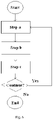
- Figure 6 shows a flow chart of a method for determining an operation condition of cable-fatigue according to an embodiment of present invention. The method is carried out based on the electro-mechanical system as illustrated above. Step a, generating a test electrical signal identifiable and injecting the test electrical signal into a first point of the at least one cable, step b, extracting the injected test electrical signal from a second point of the at least one cable; and step c, comparing a predetermined threshold with the difference between the electrical state of the injected test electrical signal (reference signal) and the extracted test electrical signal (test signal), and producing a warning signal indicating cable fatigue when the difference exceeds the predetermined threshold. If we need to continuously monitoring the cable-fatigue, then goes back to step a, otherwise, goes to end.
- Step a generating a test electrical signal identifiable and injecting the test electrical signal into a first point of the at least one cable
- step b extracting the injected test electrical signal from a second point of the at least one cable
- step c comparing a pre
- the test electrical signal is set at frequency f T
- the test electrical signal filter's centre frequency is set at f T
- the electrical loop carries an working load dispersed on a spectrum F
- the component of F at frequency f T is sufficiently small as compared to the component of the test electrical signal at frequency f T .
- the test electrical frequency f T is arranged to fall out of the spectrum F or in the interval in the spectrum F.
- step d is inserted before step a: filtering the working load with a notch filter whose centre frequency is at f T . Even if there is an obvious component at f T in said working load, the component is eliminated by the notch filter so it cannot disturb said test electrical signal. Hence, the precision of comparator is improved.
Landscapes
- Physics & Mathematics (AREA)
- General Physics & Mathematics (AREA)
- Biochemistry (AREA)
- Life Sciences & Earth Sciences (AREA)
- Chemical & Material Sciences (AREA)
- Analytical Chemistry (AREA)
- Health & Medical Sciences (AREA)
- General Health & Medical Sciences (AREA)
- Immunology (AREA)
- Pathology (AREA)
- Investigating Strength Of Materials By Application Of Mechanical Stress (AREA)
- Testing Of Devices, Machine Parts, Or Other Structures Thereof (AREA)
- Measurement Of Unknown Time Intervals (AREA)
Claims (13)
- Un moniteur pour déterminer une condition de fonctionnement d'au moins un câble qui est inclus dans une boucle électrique , comprenant :un générateur de signal électrique de test (5), pour générer un signal électrique de test identifiable et injecter le signal électrique de test dans un premier point du au moins un câble ;un filtre de signal électrique de test (7), adapté pour extraire le signal électrique de test injecté d'un second point du au moins un câble ; etun comparateur (8), pour comparer un seuil prédéterminé avec la différence entre l'état électrique du signal électrique de test injecté et le signal électrique de test extrait, et produire un signal d'avertissement indiquant la fatigue du câble lorsque la différence dépasse le seuil prédéterminé,dans lequel :le signal électrique d'essai injecté est réglé à la fréquence fT' ;la fréquence centrale du filtre du signal électrique d'essai injecté est fixée à fT;la boucle électrique porte une charge de travail dispersée sur un spectre F; etune composante de la charge de travail à la fréquence fT est suffisamment petite par rapport à une composante du signal électrique d'essai injecté à la fréquence f T'.
- Moniteur selon la revendication 1, dans lequel :
la fréquence électrique de test fT est agencée pour sortir du spectre F. - Moniteur selon la revendication 1, dans lequel :ladite boucle électrique comprenant l'un desdits au moins un câble, un premier point, une masse et un deuxième point ; etle premier point et le second point pouvant être disposés sur ledit un câble.
- Moniteur selon la revendication 1, dans lequel :ladite boucle électrique comprend un premier câble (1) dudit au moins un câble, une première partie, un deuxième câble (2) dudit au moins un câble et une deuxième partie ; etle premier point et le second point sont disposés sur le premier câble (1) et le second câble (2) du même côté par rapport aux parties de flexion et/ou de torsion des câbles.
- Moniteur selon la revendication 1, comprenant en outre :
un filtre coupe-bande (10) avec une fréquence centrale à fT étant disposé dans la boucle électrique, pour empêcher le signal électrique de test injecté d'être perturbé par la charge de travail. - Moniteur selon la revendication 1, dans lequel :
la charge de travail est une ou plusieurs sélectionnées parmi la puissance, les données numériques et les données analogiques. - Moniteur selon la revendication 1, dans lequel :
la différence est l'atténuation et/ou le flottement du signal électrique de test extrait par rapport au signal électrique de test injecté. - Procédé pour déterminer une condition de fonctionnement d'au moins un câble qui est inclus dans une boucle électrique, comprenant :(a) la génération d'un signal électrique de test identifiable et l'injection du signal électrique de test dans un premier point du au moins un câble ;(b) extraire le signal électrique d'essai injecté d'un deuxième point du au moins un câble ; et(c) comparer un seuil prédéterminé avec la différence entre l'état électrique du signal électrique d'essai injecté et le signal électrique d'essai extrait, et produire un signal d'avertissement indiquant une fatigue du câble lorsque la différence dépasse le seuil prédéterminé,dans lequel :le signal électrique d'essai injecté est réglé à la fréquence f T';la fréquence centrale du filtre du signal électrique d'essai injecté est fixée à fT;la boucle électrique porte une charge de travail dispersée sur un spectre F; etune composante de la charge de travail à la fréquence fT est suffisamment petite par rapport à une composante du signal électrique d'essai injecté à la fréquence fT',dans lequel la fréquence électrique d'essai fT est de préférence disposée pour tomber hors du spectre F.
- Procédé selon la revendication 8, dans lequel :l'un desdits au moins un câble, un premier point, la masse et un second point constituent la boucle électrique ; etle premier point et le second point sont disposés sur ledit un câble.
- Procédé selon la revendication 8, dans lequel :un premier câble (1) dudit au moins un câble, une première partie, un deuxième câble (2) dudit au moins un câble et une deuxième partie constituent la boucle électrique ; etle premier point et le second point sont respectivement disposés sur le premier câble (1) et le second câble (2) et sont disposés du même côté par rapport aux parties de flexion et/ou de torsion des câbles.
- Procédé selon la revendication 8, comprenant en outre l'étape suivante avant (a) :
(d) l'agencement d'un filtre coupe-bande (10) avec une fréquence centrale à fT dans la boucle électrique pour la charge de travail afin d'empêcher le signal électrique de test d'être perturbé par la charge de travail. - Procédé selon la revendication 8, dans lequel :
la charge de travail est choisie parmi la puissance, les données analogiques et les données numériques. - Procédé selon la revendication 8, dans lequel :
la différence est l'atténuation et/ou le flottement du signal électrique de test extrait par rapport au signal électrique de test injecté.
Applications Claiming Priority (1)
| Application Number | Priority Date | Filing Date | Title |
|---|---|---|---|
| PCT/CN2010/078566 WO2012061979A1 (fr) | 2010-11-09 | 2010-11-09 | Système de surveillance de la fatigue d'un câble et son procédé |
Publications (3)
| Publication Number | Publication Date |
|---|---|
| EP2641099A1 EP2641099A1 (fr) | 2013-09-25 |
| EP2641099A4 EP2641099A4 (fr) | 2017-12-20 |
| EP2641099B1 true EP2641099B1 (fr) | 2022-10-05 |
Family
ID=46050307
Family Applications (1)
| Application Number | Title | Priority Date | Filing Date |
|---|---|---|---|
| EP10859407.8A Active EP2641099B1 (fr) | 2010-11-09 | 2010-11-09 | Système de surveillance de la fatigue d'un câble et son procédé |
Country Status (4)
| Country | Link |
|---|---|
| US (1) | US9134358B2 (fr) |
| EP (1) | EP2641099B1 (fr) |
| CN (1) | CN103201641B (fr) |
| WO (1) | WO2012061979A1 (fr) |
Families Citing this family (15)
| Publication number | Priority date | Publication date | Assignee | Title |
|---|---|---|---|---|
| JP6163882B2 (ja) * | 2013-05-30 | 2017-07-19 | 株式会社安川電機 | 予測システム |
| CN106197975B (zh) * | 2016-07-01 | 2019-06-21 | 深圳市优必选科技有限公司 | 一种关节连接可靠性测试方法 |
| DK3483579T3 (da) * | 2017-11-08 | 2022-10-17 | Nkt Hv Cables Ab | Metode og system til træthedsovervågning af et undersøisk kabel i offshore operationer |
| DE102018204184A1 (de) * | 2018-03-19 | 2019-09-19 | Leoni Kabel Gmbh | Verfahren zur Überwachung eines Versorgungssystems eines Roboters |
| CN111086017B (zh) * | 2018-10-24 | 2024-09-13 | 发那科株式会社 | 机器人系统 |
| DE202018106543U1 (de) * | 2018-11-19 | 2019-12-20 | Igus Gmbh | System zur Leitungsüberwachung in einer Leitungsführungseinrichtung, insbesondere in einer Energieführungskette |
| CN110296905A (zh) * | 2019-07-22 | 2019-10-01 | 上海安费诺永亿通讯电子有限公司 | 一种电缆弯曲疲劳测试设备 |
| CN111351722B (zh) * | 2020-03-27 | 2022-08-16 | 珠海格力智能装备有限公司 | 工业机器人用线缆扭转模拟实验装置及方法 |
| CN111880024B (zh) * | 2020-06-30 | 2024-07-19 | 国网天津市电力公司电力科学研究院 | 测试金属纤维柔性变形过程中导电性能变化的装置和方法 |
| JP7315627B2 (ja) * | 2021-07-21 | 2023-07-26 | 株式会社安川電機 | ケーブル劣化診断装置、ケーブル劣化診断方法、及びプログラム |
| CN115127921B (zh) * | 2022-08-30 | 2022-12-13 | 江苏永鼎股份有限公司 | 一种新型传输电缆检测设备 |
| DE102022129387A1 (de) | 2022-11-07 | 2024-05-08 | Igus Gmbh | Überwachungsgerät und Verfahren zur Überwachung des Verschleißzustands einer elektrischen Leitung |
| WO2025000101A1 (fr) * | 2023-06-30 | 2025-01-02 | Nasarc Technologies Inc. | Système de surveillance de la fatigue d'un composant de chalumeau de soudage |
| WO2025210967A1 (fr) * | 2024-04-05 | 2025-10-09 | 住友電気工業株式会社 | Dispositif de détection et procédé de détection |
| WO2025210966A1 (fr) * | 2024-04-05 | 2025-10-09 | 住友電気工業株式会社 | Dispositif et procédé de détection |
Family Cites Families (18)
| Publication number | Priority date | Publication date | Assignee | Title |
|---|---|---|---|---|
| JPS5113390A (ja) | 1974-07-15 | 1976-02-02 | Daicel Ltd | Sakusanseruroosuhantomaku |
| JPS54116986A (en) | 1978-03-02 | 1979-09-11 | Mitsubishi Electric Corp | Fatigue monitor of rotating shaft |
| JPS61110029A (ja) | 1984-11-02 | 1986-05-28 | Hitachi Ltd | 小口径配管継手部の疲労監視装置 |
| US5185684A (en) * | 1991-03-28 | 1993-02-09 | Eaton Corporation | Frequency selective arc detection |
| US5452223A (en) * | 1993-08-20 | 1995-09-19 | Eaton Corporation | Arc detection using current variation |
| US5531123A (en) | 1994-11-04 | 1996-07-02 | Henkel; Daniel P. | Remote and powerless miniature fatigue monitor and method |
| JP3122012B2 (ja) | 1995-06-30 | 2001-01-09 | 京セラ株式会社 | 携帯無線電話機のアンテナ構造 |
| US5648725A (en) | 1995-09-12 | 1997-07-15 | Emerson Electric Co. | Pulse width modulation simulator for testing insulating materials |
| JPH09168226A (ja) | 1995-12-12 | 1997-06-24 | Mitsubishi Electric Corp | 保護継電装置 |
| US5637241A (en) | 1996-01-23 | 1997-06-10 | Computational Systems, Inc. | Welder cable monitor |
| US5911893A (en) * | 1996-07-24 | 1999-06-15 | Caterpillar Inc. | Arc welding method and apparatus with power cable fatigue monitor |
| JPH10111267A (ja) | 1996-10-09 | 1998-04-28 | Mitsubishi Heavy Ind Ltd | 疲労損傷モニタゲージ及び疲労損傷モニタ装置 |
| JP2000009788A (ja) | 1998-06-22 | 2000-01-14 | Sumitomo Electric Ind Ltd | ケーブルの劣化診断方法 |
| JP2001201432A (ja) | 2000-01-18 | 2001-07-27 | Kobe Steel Ltd | モニター材、モニター材を用いた疲労損傷度測定方法およびモニター材付き機械部品 |
| CN2415368Y (zh) * | 2000-03-24 | 2001-01-17 | 李治增 | 电缆断线监控器 |
| CN2466669Y (zh) * | 2001-02-19 | 2001-12-19 | 刘世春 | 多功能电缆故障检测仪 |
| CN201255757Y (zh) | 2008-08-29 | 2009-06-10 | 山东信通电器有限公司 | 电缆断线探测报警装置 |
| US20110260735A1 (en) * | 2010-04-22 | 2011-10-27 | Mccabe Paul P | Method for detecting battery cable deterioration in an industrial vehicle |
-
2010
- 2010-11-09 US US13/820,380 patent/US9134358B2/en active Active
- 2010-11-09 CN CN201080070038.6A patent/CN103201641B/zh active Active
- 2010-11-09 WO PCT/CN2010/078566 patent/WO2012061979A1/fr not_active Ceased
- 2010-11-09 EP EP10859407.8A patent/EP2641099B1/fr active Active
Also Published As
| Publication number | Publication date |
|---|---|
| US20130154676A1 (en) | 2013-06-20 |
| EP2641099A4 (fr) | 2017-12-20 |
| CN103201641B (zh) | 2015-05-20 |
| US9134358B2 (en) | 2015-09-15 |
| WO2012061979A1 (fr) | 2012-05-18 |
| CN103201641A (zh) | 2013-07-10 |
| EP2641099A1 (fr) | 2013-09-25 |
Similar Documents
| Publication | Publication Date | Title |
|---|---|---|
| EP2641099B1 (fr) | Système de surveillance de la fatigue d'un câble et son procédé | |
| EP3268760B1 (fr) | Dispositif de surveillance de terre neutre de générateur à l'aide d'une mesure et d'une analyse de composantes de courant continu | |
| JP5346472B2 (ja) | ワイヤハーネス欠陥を受動的に検出しかつ位置判定するための方法及びシステム | |
| JP5875734B2 (ja) | 電動機の診断装置および開閉装置 | |
| KR101409986B1 (ko) | 진동모니터링 결함진단장치 | |
| US7117744B2 (en) | Apparatus and method for detecting vibrations of the shaft assembly in an electrical machine | |
| CN113647013B (zh) | 电动机设备的异常诊断装置、电动机设备的异常诊断方法和电动机设备的异常诊断系统 | |
| WO2019017222A1 (fr) | Dispositif de diagnostic pour système de machine rotative, dispositif de conversion de puissance, système de machine rotative et procédé de diagnostic pour système de machine rotative | |
| JP2006170815A (ja) | ガス絶縁機器の部分放電診断方法およびシステム | |
| KR20230054455A (ko) | 기계 상태 모니터링 방법 및 기계 상태 모니터링 시스템 | |
| KR101633972B1 (ko) | 비틀림 진동의 진단 및 평가 장치와 그 방법 | |
| US11249137B2 (en) | Diagnostic method of switchgear and device thereof | |
| Glass et al. | State of the art assessment of NDE techniques for aging cable management in nuclear power plants FY2015 | |
| Kessler | The importance of partial discharge testing: PD testing has proven to be a very reliable method for detecting defects in the insulation system of electrical equipment and for assessing the risk of failure | |
| KR101477993B1 (ko) | 철도 차량의 진동 모니터링 시스템 및 방법 | |
| Glass et al. | Assessment of NDE for key indicators of aging cables in nuclear power plants–Interim status | |
| KR102457981B1 (ko) | 스플라이스의 수명을 예측하는 방법 및 장치 | |
| KR20140037502A (ko) | 변압기의 절연손상 진단장치 및 그 제어방법 | |
| Wang et al. | Diagnostics and prognostics of electric cables in nuclear power plants via joint time-frequency domain reflectometry | |
| Gheitasi | Motors fault recognition using distributed current signature analysis | |
| KR100912094B1 (ko) | 부분 방전 신호 측정시 외부 잡음 제거 방법 | |
| KR101239686B1 (ko) | 발전소 신호 모니터링 시스템 | |
| Treetrong | Fault detection and diagnosis of induction motors based on higher-order spectrum | |
| Cella et al. | Electrical rotating equipment health monitoring based on partial discharges spectrum analysis: An investigation using a wide variety of sensors | |
| JPH02122284A (ja) | ケーブル劣化診断装置 |
Legal Events
| Date | Code | Title | Description |
|---|---|---|---|
| PUAI | Public reference made under article 153(3) epc to a published international application that has entered the european phase |
Free format text: ORIGINAL CODE: 0009012 |
|
| 17P | Request for examination filed |
Effective date: 20130308 |
|
| AK | Designated contracting states |
Kind code of ref document: A1 Designated state(s): AL AT BE BG CH CY CZ DE DK EE ES FI FR GB GR HR HU IE IS IT LI LT LU LV MC MK MT NL NO PL PT RO RS SE SI SK SM TR |
|
| DAX | Request for extension of the european patent (deleted) | ||
| RA4 | Supplementary search report drawn up and despatched (corrected) |
Effective date: 20171117 |
|
| RIC1 | Information provided on ipc code assigned before grant |
Ipc: B60L 5/00 20060101ALI20171113BHEP Ipc: G01R 31/11 20060101ALI20171113BHEP Ipc: G01R 31/08 20060101AFI20171113BHEP Ipc: H02G 11/00 20060101ALI20171113BHEP Ipc: G05B 23/02 20060101ALI20171113BHEP Ipc: G01R 31/02 20060101ALI20171113BHEP Ipc: G01N 3/08 20060101ALI20171113BHEP |
|
| RAP1 | Party data changed (applicant data changed or rights of an application transferred) |
Owner name: ABB SCHWEIZ AG |
|
| GRAP | Despatch of communication of intention to grant a patent |
Free format text: ORIGINAL CODE: EPIDOSNIGR1 |
|
| RIC1 | Information provided on ipc code assigned before grant |
Ipc: G01R 31/58 20200101ALI20211102BHEP Ipc: G01M 13/00 20190101ALI20211102BHEP Ipc: H02G 11/00 20060101ALI20211102BHEP Ipc: G05B 23/02 20060101ALI20211102BHEP Ipc: B60L 5/00 20060101ALI20211102BHEP Ipc: G01N 3/08 20060101ALI20211102BHEP Ipc: G01R 31/11 20060101ALI20211102BHEP Ipc: G01R 31/50 20200101ALI20211102BHEP Ipc: G01R 31/08 20200101AFI20211102BHEP |
|
| STAA | Information on the status of an ep patent application or granted ep patent |
Free format text: STATUS: GRANT OF PATENT IS INTENDED |
|
| INTG | Intention to grant announced |
Effective date: 20211209 |
|
| GRAJ | Information related to disapproval of communication of intention to grant by the applicant or resumption of examination proceedings by the epo deleted |
Free format text: ORIGINAL CODE: EPIDOSDIGR1 |
|
| STAA | Information on the status of an ep patent application or granted ep patent |
Free format text: STATUS: REQUEST FOR EXAMINATION WAS MADE |
|
| INTC | Intention to grant announced (deleted) | ||
| GRAP | Despatch of communication of intention to grant a patent |
Free format text: ORIGINAL CODE: EPIDOSNIGR1 |
|
| STAA | Information on the status of an ep patent application or granted ep patent |
Free format text: STATUS: GRANT OF PATENT IS INTENDED |
|
| INTG | Intention to grant announced |
Effective date: 20220510 |
|
| GRAS | Grant fee paid |
Free format text: ORIGINAL CODE: EPIDOSNIGR3 |
|
| GRAA | (expected) grant |
Free format text: ORIGINAL CODE: 0009210 |
|
| STAA | Information on the status of an ep patent application or granted ep patent |
Free format text: STATUS: THE PATENT HAS BEEN GRANTED |
|
| RAP3 | Party data changed (applicant data changed or rights of an application transferred) |
Owner name: ABB SCHWEIZ AG |
|
| AK | Designated contracting states |
Kind code of ref document: B1 Designated state(s): AL AT BE BG CH CY CZ DE DK EE ES FI FR GB GR HR HU IE IS IT LI LT LU LV MC MK MT NL NO PL PT RO RS SE SI SK SM TR |
|
| REG | Reference to a national code |
Ref country code: GB Ref legal event code: FG4D |
|
| REG | Reference to a national code |
Ref country code: CH Ref legal event code: EP |
|
| REG | Reference to a national code |
Ref country code: AT Ref legal event code: REF Ref document number: 1523063 Country of ref document: AT Kind code of ref document: T Effective date: 20221015 |
|
| REG | Reference to a national code |
Ref country code: IE Ref legal event code: FG4D |
|
| REG | Reference to a national code |
Ref country code: DE Ref legal event code: R096 Ref document number: 602010068512 Country of ref document: DE |
|
| REG | Reference to a national code |
Ref country code: LT Ref legal event code: MG9D |
|
| REG | Reference to a national code |
Ref country code: AT Ref legal event code: MK05 Ref document number: 1523063 Country of ref document: AT Kind code of ref document: T Effective date: 20221005 |
|
| PG25 | Lapsed in a contracting state [announced via postgrant information from national office to epo] |
Ref country code: NL Free format text: LAPSE BECAUSE OF FAILURE TO SUBMIT A TRANSLATION OF THE DESCRIPTION OR TO PAY THE FEE WITHIN THE PRESCRIBED TIME-LIMIT Effective date: 20221005 |
|
| PG25 | Lapsed in a contracting state [announced via postgrant information from national office to epo] |
Ref country code: SE Free format text: LAPSE BECAUSE OF FAILURE TO SUBMIT A TRANSLATION OF THE DESCRIPTION OR TO PAY THE FEE WITHIN THE PRESCRIBED TIME-LIMIT Effective date: 20221005 Ref country code: PT Free format text: LAPSE BECAUSE OF FAILURE TO SUBMIT A TRANSLATION OF THE DESCRIPTION OR TO PAY THE FEE WITHIN THE PRESCRIBED TIME-LIMIT Effective date: 20230206 Ref country code: NO Free format text: LAPSE BECAUSE OF FAILURE TO SUBMIT A TRANSLATION OF THE DESCRIPTION OR TO PAY THE FEE WITHIN THE PRESCRIBED TIME-LIMIT Effective date: 20230105 Ref country code: LT Free format text: LAPSE BECAUSE OF FAILURE TO SUBMIT A TRANSLATION OF THE DESCRIPTION OR TO PAY THE FEE WITHIN THE PRESCRIBED TIME-LIMIT Effective date: 20221005 Ref country code: FI Free format text: LAPSE BECAUSE OF FAILURE TO SUBMIT A TRANSLATION OF THE DESCRIPTION OR TO PAY THE FEE WITHIN THE PRESCRIBED TIME-LIMIT Effective date: 20221005 Ref country code: ES Free format text: LAPSE BECAUSE OF FAILURE TO SUBMIT A TRANSLATION OF THE DESCRIPTION OR TO PAY THE FEE WITHIN THE PRESCRIBED TIME-LIMIT Effective date: 20221005 Ref country code: AT Free format text: LAPSE BECAUSE OF FAILURE TO SUBMIT A TRANSLATION OF THE DESCRIPTION OR TO PAY THE FEE WITHIN THE PRESCRIBED TIME-LIMIT Effective date: 20221005 |
|
| PG25 | Lapsed in a contracting state [announced via postgrant information from national office to epo] |
Ref country code: RS Free format text: LAPSE BECAUSE OF FAILURE TO SUBMIT A TRANSLATION OF THE DESCRIPTION OR TO PAY THE FEE WITHIN THE PRESCRIBED TIME-LIMIT Effective date: 20221005 Ref country code: PL Free format text: LAPSE BECAUSE OF FAILURE TO SUBMIT A TRANSLATION OF THE DESCRIPTION OR TO PAY THE FEE WITHIN THE PRESCRIBED TIME-LIMIT Effective date: 20221005 Ref country code: LV Free format text: LAPSE BECAUSE OF FAILURE TO SUBMIT A TRANSLATION OF THE DESCRIPTION OR TO PAY THE FEE WITHIN THE PRESCRIBED TIME-LIMIT Effective date: 20221005 Ref country code: IS Free format text: LAPSE BECAUSE OF FAILURE TO SUBMIT A TRANSLATION OF THE DESCRIPTION OR TO PAY THE FEE WITHIN THE PRESCRIBED TIME-LIMIT Effective date: 20230205 Ref country code: HR Free format text: LAPSE BECAUSE OF FAILURE TO SUBMIT A TRANSLATION OF THE DESCRIPTION OR TO PAY THE FEE WITHIN THE PRESCRIBED TIME-LIMIT Effective date: 20221005 Ref country code: GR Free format text: LAPSE BECAUSE OF FAILURE TO SUBMIT A TRANSLATION OF THE DESCRIPTION OR TO PAY THE FEE WITHIN THE PRESCRIBED TIME-LIMIT Effective date: 20230106 |
|
| REG | Reference to a national code |
Ref country code: CH Ref legal event code: PL |
|
| REG | Reference to a national code |
Ref country code: DE Ref legal event code: R097 Ref document number: 602010068512 Country of ref document: DE |
|
| REG | Reference to a national code |
Ref country code: BE Ref legal event code: MM Effective date: 20221130 |
|
| PG25 | Lapsed in a contracting state [announced via postgrant information from national office to epo] |
Ref country code: SM Free format text: LAPSE BECAUSE OF FAILURE TO SUBMIT A TRANSLATION OF THE DESCRIPTION OR TO PAY THE FEE WITHIN THE PRESCRIBED TIME-LIMIT Effective date: 20221005 Ref country code: RO Free format text: LAPSE BECAUSE OF FAILURE TO SUBMIT A TRANSLATION OF THE DESCRIPTION OR TO PAY THE FEE WITHIN THE PRESCRIBED TIME-LIMIT Effective date: 20221005 Ref country code: MC Free format text: LAPSE BECAUSE OF FAILURE TO SUBMIT A TRANSLATION OF THE DESCRIPTION OR TO PAY THE FEE WITHIN THE PRESCRIBED TIME-LIMIT Effective date: 20221005 Ref country code: LI Free format text: LAPSE BECAUSE OF NON-PAYMENT OF DUE FEES Effective date: 20221130 Ref country code: EE Free format text: LAPSE BECAUSE OF FAILURE TO SUBMIT A TRANSLATION OF THE DESCRIPTION OR TO PAY THE FEE WITHIN THE PRESCRIBED TIME-LIMIT Effective date: 20221005 Ref country code: DK Free format text: LAPSE BECAUSE OF FAILURE TO SUBMIT A TRANSLATION OF THE DESCRIPTION OR TO PAY THE FEE WITHIN THE PRESCRIBED TIME-LIMIT Effective date: 20221005 Ref country code: CZ Free format text: LAPSE BECAUSE OF FAILURE TO SUBMIT A TRANSLATION OF THE DESCRIPTION OR TO PAY THE FEE WITHIN THE PRESCRIBED TIME-LIMIT Effective date: 20221005 Ref country code: CH Free format text: LAPSE BECAUSE OF NON-PAYMENT OF DUE FEES Effective date: 20221130 |
|
| PLBE | No opposition filed within time limit |
Free format text: ORIGINAL CODE: 0009261 |
|
| STAA | Information on the status of an ep patent application or granted ep patent |
Free format text: STATUS: NO OPPOSITION FILED WITHIN TIME LIMIT |
|
| PG25 | Lapsed in a contracting state [announced via postgrant information from national office to epo] |
Ref country code: SK Free format text: LAPSE BECAUSE OF FAILURE TO SUBMIT A TRANSLATION OF THE DESCRIPTION OR TO PAY THE FEE WITHIN THE PRESCRIBED TIME-LIMIT Effective date: 20221005 Ref country code: LU Free format text: LAPSE BECAUSE OF NON-PAYMENT OF DUE FEES Effective date: 20221109 Ref country code: AL Free format text: LAPSE BECAUSE OF FAILURE TO SUBMIT A TRANSLATION OF THE DESCRIPTION OR TO PAY THE FEE WITHIN THE PRESCRIBED TIME-LIMIT Effective date: 20221005 |
|
| 26N | No opposition filed |
Effective date: 20230706 |
|
| GBPC | Gb: european patent ceased through non-payment of renewal fee |
Effective date: 20230105 |
|
| PG25 | Lapsed in a contracting state [announced via postgrant information from national office to epo] |
Ref country code: IE Free format text: LAPSE BECAUSE OF NON-PAYMENT OF DUE FEES Effective date: 20221109 Ref country code: GB Free format text: LAPSE BECAUSE OF NON-PAYMENT OF DUE FEES Effective date: 20230105 |
|
| PG25 | Lapsed in a contracting state [announced via postgrant information from national office to epo] |
Ref country code: SI Free format text: LAPSE BECAUSE OF FAILURE TO SUBMIT A TRANSLATION OF THE DESCRIPTION OR TO PAY THE FEE WITHIN THE PRESCRIBED TIME-LIMIT Effective date: 20221005 Ref country code: FR Free format text: LAPSE BECAUSE OF NON-PAYMENT OF DUE FEES Effective date: 20221205 Ref country code: BE Free format text: LAPSE BECAUSE OF NON-PAYMENT OF DUE FEES Effective date: 20221130 |
|
| PG25 | Lapsed in a contracting state [announced via postgrant information from national office to epo] |
Ref country code: HU Free format text: LAPSE BECAUSE OF FAILURE TO SUBMIT A TRANSLATION OF THE DESCRIPTION OR TO PAY THE FEE WITHIN THE PRESCRIBED TIME-LIMIT; INVALID AB INITIO Effective date: 20101109 |
|
| PG25 | Lapsed in a contracting state [announced via postgrant information from national office to epo] |
Ref country code: CY Free format text: LAPSE BECAUSE OF FAILURE TO SUBMIT A TRANSLATION OF THE DESCRIPTION OR TO PAY THE FEE WITHIN THE PRESCRIBED TIME-LIMIT Effective date: 20221005 |
|
| PG25 | Lapsed in a contracting state [announced via postgrant information from national office to epo] |
Ref country code: MK Free format text: LAPSE BECAUSE OF FAILURE TO SUBMIT A TRANSLATION OF THE DESCRIPTION OR TO PAY THE FEE WITHIN THE PRESCRIBED TIME-LIMIT Effective date: 20221005 Ref country code: IT Free format text: LAPSE BECAUSE OF FAILURE TO SUBMIT A TRANSLATION OF THE DESCRIPTION OR TO PAY THE FEE WITHIN THE PRESCRIBED TIME-LIMIT Effective date: 20221005 |
|
| PG25 | Lapsed in a contracting state [announced via postgrant information from national office to epo] |
Ref country code: BG Free format text: LAPSE BECAUSE OF FAILURE TO SUBMIT A TRANSLATION OF THE DESCRIPTION OR TO PAY THE FEE WITHIN THE PRESCRIBED TIME-LIMIT Effective date: 20221005 |
|
| PG25 | Lapsed in a contracting state [announced via postgrant information from national office to epo] |
Ref country code: MT Free format text: LAPSE BECAUSE OF FAILURE TO SUBMIT A TRANSLATION OF THE DESCRIPTION OR TO PAY THE FEE WITHIN THE PRESCRIBED TIME-LIMIT Effective date: 20221005 |
|
| PG25 | Lapsed in a contracting state [announced via postgrant information from national office to epo] |
Ref country code: TR Free format text: LAPSE BECAUSE OF FAILURE TO SUBMIT A TRANSLATION OF THE DESCRIPTION OR TO PAY THE FEE WITHIN THE PRESCRIBED TIME-LIMIT Effective date: 20221005 |
|
| PGFP | Annual fee paid to national office [announced via postgrant information from national office to epo] |
Ref country code: DE Payment date: 20251119 Year of fee payment: 16 |