EP2641322B1 - Energieversorgungssystem mit einem multiphasenmatrixumrichter und verfahren zum betrieb desselben - Google Patents
Energieversorgungssystem mit einem multiphasenmatrixumrichter und verfahren zum betrieb desselben Download PDFInfo
- Publication number
- EP2641322B1 EP2641322B1 EP11704572.4A EP11704572A EP2641322B1 EP 2641322 B1 EP2641322 B1 EP 2641322B1 EP 11704572 A EP11704572 A EP 11704572A EP 2641322 B1 EP2641322 B1 EP 2641322B1
- Authority
- EP
- European Patent Office
- Prior art keywords
- supply system
- power supply
- voltage
- transformer
- control unit
- Prior art date
- Legal status (The legal status is an assumption and is not a legal conclusion. Google has not performed a legal analysis and makes no representation as to the accuracy of the status listed.)
- Not-in-force
Links
- 239000011159 matrix material Substances 0.000 title claims description 29
- 238000000034 method Methods 0.000 title claims description 9
- 230000002457 bidirectional effect Effects 0.000 claims description 13
- 230000001960 triggered effect Effects 0.000 claims description 4
- 230000001133 acceleration Effects 0.000 claims description 2
- 238000011161 development Methods 0.000 description 3
- 230000018109 developmental process Effects 0.000 description 3
- 238000000926 separation method Methods 0.000 description 2
- 230000003044 adaptive effect Effects 0.000 description 1
- 238000004891 communication Methods 0.000 description 1
- 230000001419 dependent effect Effects 0.000 description 1
- 238000005259 measurement Methods 0.000 description 1
- 230000003534 oscillatory effect Effects 0.000 description 1
- 238000012552 review Methods 0.000 description 1
Images


Classifications
-
- H—ELECTRICITY
- H02—GENERATION; CONVERSION OR DISTRIBUTION OF ELECTRIC POWER
- H02M—APPARATUS FOR CONVERSION BETWEEN AC AND AC, BETWEEN AC AND DC, OR BETWEEN DC AND DC, AND FOR USE WITH MAINS OR SIMILAR POWER SUPPLY SYSTEMS; CONVERSION OF DC OR AC INPUT POWER INTO SURGE OUTPUT POWER; CONTROL OR REGULATION THEREOF
- H02M7/00—Conversion of AC power input into DC power output; Conversion of DC power input into AC power output
- H02M7/42—Conversion of DC power input into AC power output without possibility of reversal
- H02M7/44—Conversion of DC power input into AC power output without possibility of reversal by static converters
- H02M7/48—Conversion of DC power input into AC power output without possibility of reversal by static converters using discharge tubes with control electrode or semiconductor devices with control electrode
-
- H—ELECTRICITY
- H02—GENERATION; CONVERSION OR DISTRIBUTION OF ELECTRIC POWER
- H02M—APPARATUS FOR CONVERSION BETWEEN AC AND AC, BETWEEN AC AND DC, OR BETWEEN DC AND DC, AND FOR USE WITH MAINS OR SIMILAR POWER SUPPLY SYSTEMS; CONVERSION OF DC OR AC INPUT POWER INTO SURGE OUTPUT POWER; CONTROL OR REGULATION THEREOF
- H02M5/00—Conversion of AC power input into AC power output, e.g. for change of voltage, for change of frequency, for change of number of phases
- H02M5/02—Conversion of AC power input into AC power output, e.g. for change of voltage, for change of frequency, for change of number of phases without intermediate conversion into DC
- H02M5/04—Conversion of AC power input into AC power output, e.g. for change of voltage, for change of frequency, for change of number of phases without intermediate conversion into DC by static converters
- H02M5/22—Conversion of AC power input into AC power output, e.g. for change of voltage, for change of frequency, for change of number of phases without intermediate conversion into DC by static converters using discharge tubes with control electrode or semiconductor devices with control electrode
- H02M5/25—Conversion of AC power input into AC power output, e.g. for change of voltage, for change of frequency, for change of number of phases without intermediate conversion into DC by static converters using discharge tubes with control electrode or semiconductor devices with control electrode using devices of a thyratron or thyristor type requiring extinguishing means
- H02M5/27—Conversion of AC power input into AC power output, e.g. for change of voltage, for change of frequency, for change of number of phases without intermediate conversion into DC by static converters using discharge tubes with control electrode or semiconductor devices with control electrode using devices of a thyratron or thyristor type requiring extinguishing means for conversion of frequency
- H02M5/271—Conversion of AC power input into AC power output, e.g. for change of voltage, for change of frequency, for change of number of phases without intermediate conversion into DC by static converters using discharge tubes with control electrode or semiconductor devices with control electrode using devices of a thyratron or thyristor type requiring extinguishing means for conversion of frequency from a three phase input voltage
-
- B—PERFORMING OPERATIONS; TRANSPORTING
- B60—VEHICLES IN GENERAL
- B60L—PROPULSION OF ELECTRICALLY-PROPELLED VEHICLES; SUPPLYING ELECTRIC POWER FOR AUXILIARY EQUIPMENT OF ELECTRICALLY-PROPELLED VEHICLES; ELECTRODYNAMIC BRAKE SYSTEMS FOR VEHICLES IN GENERAL; MAGNETIC SUSPENSION OR LEVITATION FOR VEHICLES; MONITORING OPERATING VARIABLES OF ELECTRICALLY-PROPELLED VEHICLES; ELECTRIC SAFETY DEVICES FOR ELECTRICALLY-PROPELLED VEHICLES
- B60L50/00—Electric propulsion with power supplied within the vehicle
-
- H—ELECTRICITY
- H02—GENERATION; CONVERSION OR DISTRIBUTION OF ELECTRIC POWER
- H02M—APPARATUS FOR CONVERSION BETWEEN AC AND AC, BETWEEN AC AND DC, OR BETWEEN DC AND DC, AND FOR USE WITH MAINS OR SIMILAR POWER SUPPLY SYSTEMS; CONVERSION OF DC OR AC INPUT POWER INTO SURGE OUTPUT POWER; CONTROL OR REGULATION THEREOF
- H02M5/00—Conversion of AC power input into AC power output, e.g. for change of voltage, for change of frequency, for change of number of phases
- H02M5/02—Conversion of AC power input into AC power output, e.g. for change of voltage, for change of frequency, for change of number of phases without intermediate conversion into DC
- H02M5/04—Conversion of AC power input into AC power output, e.g. for change of voltage, for change of frequency, for change of number of phases without intermediate conversion into DC by static converters
- H02M5/22—Conversion of AC power input into AC power output, e.g. for change of voltage, for change of frequency, for change of number of phases without intermediate conversion into DC by static converters using discharge tubes with control electrode or semiconductor devices with control electrode
- H02M5/275—Conversion of AC power input into AC power output, e.g. for change of voltage, for change of frequency, for change of number of phases without intermediate conversion into DC by static converters using discharge tubes with control electrode or semiconductor devices with control electrode using devices of a triode or transistor type requiring continuous application of a control signal
- H02M5/297—Conversion of AC power input into AC power output, e.g. for change of voltage, for change of frequency, for change of number of phases without intermediate conversion into DC by static converters using discharge tubes with control electrode or semiconductor devices with control electrode using devices of a triode or transistor type requiring continuous application of a control signal for conversion of frequency
-
- H—ELECTRICITY
- H02—GENERATION; CONVERSION OR DISTRIBUTION OF ELECTRIC POWER
- H02P—CONTROL OR REGULATION OF ELECTRIC MOTORS, ELECTRIC GENERATORS OR DYNAMO-ELECTRIC CONVERTERS; CONTROLLING TRANSFORMERS, REACTORS OR CHOKE COILS
- H02P27/00—Arrangements or methods for the control of AC motors characterised by the kind of supply voltage
- H02P27/04—Arrangements or methods for the control of AC motors characterised by the kind of supply voltage using variable-frequency supply voltage, e.g. inverter or converter supply voltage
- H02P27/06—Arrangements or methods for the control of AC motors characterised by the kind of supply voltage using variable-frequency supply voltage, e.g. inverter or converter supply voltage using DC to AC converters or inverters
Definitions
- the invention relates to a power supply system with a multi-phase matrix converter having a plurality of input terminals, a plurality of output terminals and a plurality of subconductors, wherein the input terminals are respectively connected via bidirectional switches of the partial converter to the output terminals.
- the invention relates to a method for operating a power supply system with a multi-phase matrix converter.
- Such a power supply system with a multi-phase matrix converter is in DE 20 2005 001 686 U1 disclosed.
- the matrix converter is connected in a known manner to an AC system, such as in FIG. 1 shown.
- expensive mains filters must be provided in the grid feed for the reduction of the harmonics, which deteriorate the efficiency degree due to their losses.
- the DC voltage for feeding into the public grid e.g. the 380V network
- the DC voltage for feeding into the public grid are first converted into a mains-synchronous AC voltage.
- mains-controlled inverters For this serve mains-controlled inverters.
- phase voltages of up to 1,000 V are currently used as the input voltage for a downstream converter.
- undesirable oscillatory behavior can occur due to the fluctuating charge stored in the plant capacitances distributed over the photovoltaic field.
- a photovoltaic array is connected in parallel and the energy is transported over larger cable cross-sections to a central inverter.
- Several such inverters are connected to the grid via a medium voltage or high voltage transformer.
- HF resonators are used to avoid resonances, as shown in the 2005 release "A review of single-phase grid-connected inverters for photovoltaic modules".
- the invention is therefore based on the object to propose a power supply system of the above type and a method for operating such a power supply system, the energy supply from a plurality of DC power sources, e.g. from a photovoltaic field, to supply three-phase loads in a simple manner.
- a circuit is connected to the input terminals, which has at least one DC voltage source, an inverter connected in series therewith for generating a first AC voltage and an inverter connected in series RF converter.
- the RF converter is used to increase the first AC voltage to a second AC voltage and to change the frequency of the second AC voltage with respect to the first AC voltage by a multiple.
- a control unit is provided, which controls the bidirectional switches of the multi-phase matrix converter and the RF converter in dependence on the instantaneous values of current and voltage at the output of the DC voltage sources and in dependence on the output of the RF converter pending second AC voltage.
- the further object relating to the method is achieved with the features of claim 10.
- the present at the output terminals sinusoidal AC voltages for the phases of the three-phase network are formed by voltage pulses of different duration and height from the pending at the outputs of the RF converter AC voltages by the Control unit controls the bidirectional switch such that the voltage pulses are passed to the output terminals.
- the duration and height of the transmitted voltage pulses are changed by the control unit as needed.
- control by the control unit in response to active and / or reactive power specifications, e.g. a network operator.
- a particular advantage is when according to claim 4 present at the output terminals sinusoidal AC voltages for the phases of a three-phase network, which are formed by voltage pulses of different duration and height and are triggered by the control unit from the bidirectional switches on the output terminals of the multi-phase matrix converter, wherein the Duration and height of the transmitted voltage pulses can be changed by the control unit.
- the power supply system for driving a battery-powered vehicle is used wherein the DC voltage source is designed as a battery.
- FIG. 1 is a known from the prior art circuit topology of a power supply system with a matrix converter, wherein at the input side of the matrix converter via the lines L1, L2, L3, a three-phase network AC is connected and the output terminals are connected to a motor MO.
- the matrix converter is shown in simplified form with switching elements which are in reality designed as bidirectional switches.
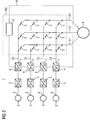
- an inventive energy supply system 1 is shown with a multi-phase matrix converter MU having a plurality of input terminals E1, E2, E3, E4, a plurality of output terminals A1, A2, A3 and a plurality of partial converter.
- the input terminals E1, E2, E3, E4 are each connected via bidirectional switches S of the partial converter with the output terminals A1, A2, A3, which are connected here to a public network.
- a circuit is connected to the input terminals E1, E2, E3, E4, the at least one DC voltage source 2, an inverter connected in series 3 for generating a first AC voltage, here a square wave voltage, and an inverter connected to the inverter 3 in series RF Converter 4 has.
- the inverter 3 is designed with local, self-contained MPP tracking, where MPP means Maximum Power Point.
- the RF converter 4 serves to increase the first alternating voltage into a second alternating voltage and to increase the frequency of the second alternating voltage the frequency of the first alternating voltage by a multiple.
- the multi-phase matrix converter MU comprises a control unit 5, which controls the bidirectional switches S of the multi-phase matrix converter MU as a function of the output 7 of the RF converter 4 pending second AC voltage.
- the control unit 5 is connected via a communication line 8 to the RF converters 4. If necessary, current and voltage at the output 6 of the DC voltage sources 2 are transmitted to the control unit 5.
- the RF converter 4 receives via the control unit 5, the setpoint values for the pulse shape, which is generated in a local control loop in the RF converter 4.
- the multiphase matrix converter MU measuring points are present at the output of the RF converter 4 for all second alternating voltages, which supply the instantaneous voltage values to the control unit 5. If the setpoint values here deviate from the values measured in the multi-phase matrix converter MU, parameters in the control unit 5 are adapted. This can e.g. be necessary for large cable lengths between RF converter 4 and the multi-phase matrix inverter MU.
- DC voltage sources 2 When using such an energy supply system 1 for feeding the energy provided by a photovoltaic array into a public grid 9, individual areas of the photovoltaic array serve as DC voltage sources 2. Any number of DC voltage sources 2 can be used for this purpose.
- the sinusoidal alternating voltages for the phases of the three-phase network 9 are formed by voltage pulses of different duration and height, which triggered triggered by the control unit 5 of the bidirectional switches S to the output terminals A1, A2, A3 of the multi-phase matrix converter MU become.
- the duration and height of the transmitted voltage pulses can be changed by the control unit 5.
- FIG. 3 shows in principle how a section of a positive sine half-wave of an alternating voltage can be reproduced by positive voltage blocks Bp different height and width.
- These voltage blocks Bp for the positive sine half-wave are according to FIG. 4
- the two square-wave voltages of two RF transducers 4 are generated.
- control unit 5 can generate a new suitable pulse pattern by an adaptive algorithm and distribute it to all inverters so that the multi-phase matrix converter MU can operate in the optimum range.
- control unit 5 By means of the control unit 5, the effective and / or reactive power delivered to the network can be controlled in accordance with the specifications of the network operator via the multi-phase matrix converter MU. Also, power quality specifications, e.g. to the harmonic content, can be implemented by the control unit 5 by appropriate control.
- the power supply system 1 according to FIG. 2 can also be used advantageously for driving a battery-powered vehicle.
- the batteries serve as DC voltage sources and an electric motor is connected to the output terminals A1, A2, A3 of the multi-phase matrix converter MU.
- the RF converter 4 and the multi-phase matrix converter MU are encapsulated in a common housing as a module, which forms a contact protection against the plant parts with high voltage.
- an electrical separation point is provided, which are opened by the control unit 5 after measurement of an accidentally high acceleration value.
- the electrical separation point can be performed for example as an electromechanical or electronic switch.
- a change in the DC voltage at the output of a DC voltage source 2 or the complete failure of the same, resulting in a change in the amplitude of the second AC voltage at the output of the downstream RF converter 4 is compensated by adapted control of the RF converter 4 and the multi-phase matrix converter MU.
Landscapes
- Engineering & Computer Science (AREA)
- Power Engineering (AREA)
- Transportation (AREA)
- Mechanical Engineering (AREA)
- Ac-Ac Conversion (AREA)
- Inverter Devices (AREA)
- Electric Propulsion And Braking For Vehicles (AREA)
- Charge And Discharge Circuits For Batteries Or The Like (AREA)
Description
- Die Erfindung betrifft ein Energieversorgungssystem mit einem Multiphasenmatrixumrichter, der mehrere Eingangsklemmen, mehrere Ausgangsklemmen und mehrere Teilumrichter aufweist, wobei die Eingangsklemmen jeweils über bidirektionale Schalter der Teilumrichter mit den Ausgangsklemmen verbunden sind.
- Außerdem betrifft die Erfindung ein Verfahren zum Betrieb eines Energieversorgungssystems mit einem Multiphasenmatrixumrichter.
- Ein derartiges Energieversorgungssystem mit einem Multiphasenmatrixumrichter ist in der
DE 20 2005 001 686 U1 offenbart. Dabei ist der Matrixumrichter in bekannter Weise an ein Wechselstromsystem angebunden, wie beispielsweise inFigur 1 dargestellt. Bei solchen Anlagen müssen in der Netzeinspeisung teure Netzfilter zur Reduzierung der Oberschwingungen vorgesehen werden, die aufgrund ihrer Verluste den Wirkungs-grad verschlechtern. - Bei Energieversorgungssystemen mit Photovoltaikanlagen als Gleichspannungsquelle muss die Gleichspannung zum Einspeisen in das öffentliche Stromnetz, z.B. das 380V-Netz, erst in eine netzsynchrone Wechselspannung umgewandelt werden. Hierzu dienen netzgeführte Wechselrichter.
- Große Photovoltaikfelder sind in Einzelstränge unterteilt. Dabei werden zurzeit Strangspannungen bis zu 1.000V als Eingangsspannung für einen nachgeschalteten Umrichter angewandt. Es kann bei solchen Photovoltaikanlagen zu unerwünschtem Schwingverhalten aufgrund der in den über das Photovoltaikfeld verteilten Anlagekapazitäten gespeicherten schwankenden Ladung kommen .
- Zur Vermeidung dieses Problems sowie anderer Nachteile dieser Ausführungsform werden mehrere Stränge eines Photovoltaikfeldes parallel geschaltet und die Energie über größere Kabelquerschnitte zu einem zentralen Wechselrichter befördert. Mehrere solcher Wechselrichter werden über einen Mittelspannungs- oder Hochspannungstransformator an das Netz angeschlossen. Zur Vermeidung von Resonanzen dienen HF-Transformatoren, wie aus der veröffentlichung "A review of single-phase grid-connected inverters for photoroltaic modules" aus dem jahre 2005 hervorgeht. Der Erfindung liegt daher die Aufgabe zugrunde, ein Energieversorgungssystem der oben genannten Art und ein Verfahren zum Betrieb eines solchen Energieversorgungssystems vorzuschlagen, das die Energieeinspeisung aus mehreren Gleichspannungsquellen, z.B. aus einem Photovoltaikfeld, zur Versorgung von Drehstromverbrauchern auf einfache Weise ermöglicht.
- Die Aufgabe wird zum einen durch ein Energieversorgungssystem mit den Merkmalen nach Anspruch 1 gelöst. Dabei ist an die Eingangsklemmen jeweils eine Schaltung angeschlossen, die mindestens eine Gleichspannungsquelle, einen zu dieser in Reihe geschalteten Wechselrichter zur Erzeugung einer ersten Wechselspannung sowie einen zum Wechselrichter in Reihe geschalteten HF-Umsetzer aufweist. Der HF-Umsetzer dient zur Hochsetzung der ersten Wechselspannung in eine zweite Wechselspannung und zur Veränderung der Frequenz der zweiten Wechselspannung gegenüber der ersten Wechselspannung um ein Vielfaches. Weiterhin ist eine Steuereinheit vorgesehen, die die bidirektionalen Schalter des Multiphasenmatrixumrichters sowie die HF-Umsetzer in Abhängigkeit von den Augenblickswerten von Strom und Spannung am Ausgang der Gleichspannungsquellen sowie in Abhängigkeit der am Ausgang der HF-Umsetzer anstehenden zweiten Wechselspannung ansteuert.
- Die weitere das Verfahren betreffende Aufgabe wird mit den Merkmalen nach Anspruch 10 gelöst. Dabei werden die an den Ausgangsklemmen anstehenden sinusförmigen Wechselspannungen für die Phasen des Drehstromnetzes durch Spannungspulse unterschiedlicher Dauer und Höhe aus den an den Ausgängen der HF-Umsetzer anstehenden Wechselspannungen gebildet, indem die Steuereinheit die bidirektionalen Schalter derart ansteuert, dass die Spannungspulse auf die Ausgangsklemmen geleitet werden. Dabei werden die Dauer und Höhe der durchgeleiteten Spannungspulse durch die Steuereinheit nach Bedarf verändert.
- Vorteilhafte Weiterbildungen der Erfindung sind den Unteransprüchen 2 bis 9 und 11 bis 13 zu entnehmen.
- Eine vorteilhafte Weiterbildung der Erfindung besteht, wenn gemäß Anspruch 2 die Gleichspannungsquellen als Bereiche eines Photovoltaikfelds ausgeführt sind.
- Weiterhin ist es vorteilhaft, wenn gemäß Anspruch 3 die Steuerung durch die Steuereinheit in Abhängigkeit von Wirk- und/ oder Blindleistungsvorgaben, z.B. eines Netzbetreibers, erfolgt.
- Ein besonderer Vorteil besteht, wenn gemäß Anspruch 4 an den Ausgangsklemmen sinusförmige Wechselspannungen für die Phasen eines Drehstromnetzes anstehen, die durch Spannungspulse unterschiedlicher Dauer und Höhe gebildet sind und die ausgelöst durch die Steuereinheit von den bidirektionalen Schaltern auf die Ausgangsklemmen des Multiphasenmatrixumrichters geleitet werden, wobei die Dauer und Höhe der durchgeleiteten Spannungspulse durch die Steuereinheit veränderbar ist.
- Gemäß den Ansprüchen 5 und 6 dient das Energieversorgungssystem zum Antrieb eines batteriebetriebenen Fahrzeugs wobei die Gleichspannungsquelle als Batterie ausgeführt ist.
- Die Weiterbildungen des erfindungsgemäßen Verfahrens entsprechen den vorteilhaften Ausbildungen des erfindungsgemäßen Energieversorgungssystems.
- Ein Ausführungsbeispiel der Erfindung wird im Folgenden anhand einer Zeichnung näher erläutert. Es zeigen:
- FIG 1
- eine aus dem Stand der Technik bekannte Schaltungstopologie eines Energieversorgungssystems mit einem Matrixumrichter,
- FIG 2
- die Schaltungstopologie eines erfindungsgemäßen Energieversorgungssystems mit einem Multiphasenmatrixumrichter,
- FIG 3
- eine aus mehreren Spannungsblöcken gebildete Halbwelle einer sinusförmigen Wechselspannung und
- FIG 4
- einen aus mehreren Spannungspulsen gebildeten Spannungsblock.
- In
FIG 1 ist eine aus dem Stand der Technik bekannte Schaltungstopologie eines Energieversorgungssystems mit einem Matrixumrichter dargestellt, wobei an der Eingangsseite der Matrixumrichter über die Leitungen L1, L2, L3 ein Drehstromnetz AC angeschlossen ist und die Ausgangsklemmen mit einem Motor MO verbunden sind. Dabei ist der Matrixumrichter vereinfachend mit Schaltelementen dargestellt, die in Realität als bidirektionale Schalter ausgeführt sind. - In
FIG 2 ist ein erfindungsgemäßes Energieversorgungssystem 1 mit einem Multiphasenmatrixumrichter MU dargestellt, der mehrere Eingangsklemmen E1,E2,E3,E4, mehrere Ausgangsklemmen A1, A2, A3 und mehrere Teilumrichter aufweist. Die Eingangsklemmen E1,E2,E3,E4 sind jeweils über bidirektionale Schalter S der Teilumrichter mit den Ausgangsklemmen A1, A2, A3 verbunden, die hier an ein öffentliches Netz angeschlossen sind. - An die Eingangsklemmen E1,E2,E3,E4 ist jeweils eine Schaltung angeschlossen, die mindestens eine Gleichspannungsquelle 2, einen zu dieser in Reihe geschalteten Wechselrichter 3 zur Erzeugung einer ersten Wechselspannung, hier einer Rechteckspannung, sowie einen zum Wechselrichter 3 in Reihe geschalteten HF-Umsetzer 4 aufweist. Der Wechselrichter 3 ist mit lokalem, autarkem MPP-Tracking ausgeführt, wobei MPP Maximum Power Point bedeutet. Der HF-Umsetzer 4 dient zur Hochsetzung der ersten Wechselspannung in eine zweite Wechselspannung und zur Erhöhung der Frequenz der zweiten Wechselspannung gegenüber der Frequenz der ersten Wechselspannung um ein Vielfaches. Der Multiphasenmatrixumrichter MU umfasst eine Steuereinheit 5, die die bidirektionalen Schalter S des Multiphasenmatrixumrichters MU in Abhängigkeit der am Ausgang 7 der HF-Umsetzer 4 anstehenden zweiten Wechselspannung ansteuert. Hierzu ist die Steuereinheit 5 über eine Kommunikationsleitung 8 mit den HF-Umsetzern 4 verbunden. Bei Bedarf werden Strom und Spannung am Ausgang 6 der Gleichspannungsquellen 2 an die Steuereinheit 5 übertragen.
- Der HF-Umsetzer 4 bezieht über die Steuereinheit 5 die Sollwerte für die Pulsform, die in einem lokalen Regelkreis im HF-Umsetzer 4 erzeugt wird. Im Multiphasenmatrixumrichter MU sind für alle zweiten Wechselspannungen am Ausgang der HF-Umsetzer 4 Messstellen vorhanden, die die Augenblicksspannungswerte an die Steuereinheit 5 liefern. Wenn hier die Sollwerte von den im Multiphasenmatrixumrichter MU gemessenen Werten abweichen, werden Parameter in der Steuereinheit 5 angepasst. Dies kann z.B. bei großen Kabellängen zwischen HF-Umsetzer 4 und dem Multiphasenmatrixumrichter MU nötig sein.
- Beim Einsatz eines solchen Energieversorgungssystems 1 zur Einspeisung der durch ein Photovoltaikfeld bereitgestellten Energie in ein öffentliches Netz 9 dienen einzelne Bereiche des Photovoltaikfelds als Gleichspannungsquellen 2. Dabei kann eine beliebige Anzahl von Gleichspannungsquellen 2 zum Einsatz kommen.
- Es können mehrere parallel geschaltete Einzelstränge des Photovoltaikfeldes als Gleichspannungsquelle 2 dienen. Weiterhin können auch mehrere Wechselrichter 3 den nachgeschalteten HF-Umsetzer 4 speisen.
- Die sinusförmigen Wechselspannungen für die Phasen des Drehstromnetzes 9 werden dabei durch Spannungspulse unterschiedlicher Dauer und Höhe gebildet, die ausgelöst durch die Steuereinheit 5 von den bidirektionalen Schaltern S auf die Ausgangsklemmen A1,A2,A3 des Multiphasenmatrixumrichters MU geleitet werden. Die Dauer und Höhe der durchgeleiteten Spannungspulse ist durch die Steuereinheit 5 veränderbar ist.
- Dies wird beispielhaft anhand der
FIG 3 und 4 erläutert.FIG 3 zeigt prinzipiell wie ein Abschnitt einer positiven Sinushalbwelle einer Wechselspannung durch positive Spannungsblöcke Bp unterschiedlicher Höhe und Breite nachgebildet werden kann. Diese Spannungsblöcke Bp für die positive Sinushalbwelle sind gemäßFIG 4 z.B. aus den positiven Einzelpulsen zweier Rechteckspannungen U1 und U2 zusammengesetzt, die dieselbe Amplitude und Frequenz haben, aber um 180 Grad phasenverschoben sind, wobei die beiden Rechteckspannungen von zwei HF-Umsetzern 4 generiert werden. - Bei Abschaltung eines Strangs in einem Photovoltaikfeld kann die Steuereinheit 5 durch einen adaptiven Algorithmus ein neues passendes Pulsmuster generieren und auf alle Umrichter verteilen, so dass der Multiphasenmatrixumrichter MU im optimalen Bereich arbeiten kann.
- Durch die Steuereinheit 5 kann über den Multiphasenmatrixumrichter MU die an das Netz abgegebene Wirk- und/oder Blindleistung entsprechend den Vorgaben des Netzbetreibers gesteuert werden. Auch Vorgaben zur Netzqualität, z.B. zum Oberschwingungsgehalt, können von der Steuereinheit 5 durch entsprechende Steuerung umgesetzt werden.
- Das Energieversorgungssystem 1 nach
FIG 2 kann vorteilhaft auch für den Antrieb eines batteriebetriebenen Fahrzeugs genutzt werden. Die Batterien dienen hierbei als Gleichspannungsquellen und an die Ausgangsklemmen A1,A2,A3 des Multiphasenmatrixumrichters MU wird ein Elektromotor angeschlossen. Die HF-Umsetzer 4 und der Multiphasenmatrixumrichter MU werden in einem gemeinsamen Gehäuse als Modul gekapselt, das einen Berührungsschutz gegenüber den Anlagenteilen mit hoher Spannung bildet. - Zwischen jeder Batterie und dem dazu in Reihe geschalteten HF-Umsetzer 4 wird eine elektrische Trennstelle vorgesehen, die durch die Steuereinheit 5 nach Messung eines unfallbedingt hohen Beschleunigungswertes geöffnet werden. Die elektrische Trennstelle kann beispielsweise als elektromechanischer oder elektronischer Schalter ausgeführt werden.
- Eine Veränderung der Gleichspannung am Ausgang einer Gleichspannungsquelle 2 oder der völlige Ausfall derselben, was eine Veränderung der Amplitude der zweiten Wechselspannung am Ausgang des nachgeschalteten HF-Umsetzers 4 zur Folge hat, wird durch angepasste Steuerung des HF-Umsetzers 4 und des Multiphasenmatrixumrichters MU ausgeglichen.
Claims (13)
- Energieversorgungssystem (1) mit einem Multiphasenmatrixumrichter (MU), der mehrere Eingangsklemmen (E1,E2,E3,E4), mehrere Ausgangsklemmen (A1, A2, A3) und mehrere Teilumrichter aufweist, wobei die Eingangsklemmen (E1,E2,E3,E4) jeweils über bidirektionale Schalter (S) der Teilumrichter mit den Ausgangsklemmen (A1, A2, A3) verbunden sind, dadurch gekennzeichnet, dass an die Eingangsklemmen (E1,E2,E3,E4) jeweils eine Schaltung angeschlossen ist, die mindestens eine Gleichspannungsquelle (2), einen zu dieser in Reihe geschalteten Wechselrichter (3) zur Erzeugung einer ersten Wechselspannung sowie einen zum Wechselrichter in Reihe geschalteten HF-Umsetzer (4) aufweist, wobei der HF-Umsetzer (4) zur Hochsetzung der ersten Wechselspannung in eine zweite Wechselspannung und zur Veränderung der Frequenz der zweiten Wechselspannung gegenüber der Frequenz der ersten Wechselspannung um ein Vielfaches dient, und dass eine Steuereinheit (5) vorgesehen ist, die die bidirektionalen Schalter (S) des Multiphasenmatrixumrichters (MU) in Abhängigkeit der am Ausgang der HF-Umsetzer (4) anstehenden zweiten Wechselspannung ansteuert.
- Energieversorgungssystem nach Anspruch 1, dadurch gekennzeichnet, dass die Gleichspannungsquellen (2) als Bereiche eines Photovoltaikfeldes ausgeführt sind.
- Energieversorgungssystem nach Anspruch 1 oder 2, dadurch gekennzeichnet, dass die Steuerung durch die Steuereinheit (5) in Abhängigkeit von Wirk- und/oder Blindleistungsvorgaben, z.B. eines Netzbetreibers, erfolgt.
- Energieversorgungssystem nach einem der vorangehenden Ansprüche, dadurch gekennzeichnet, dass an den Ausgangsklemmen (A1, A2, A3) sinusförmige Wechselspannungen für die Phasen eines Drehstromnetzes (9) anstehen, die durch Spannungspulse unterschiedlicher Dauer und Höhe gebildet sind und die ausgelöst durch die Steuereinheit (5) von den bidirektionalen Schaltern (S) auf die Ausgangsklemmen (A1,A2,A3) des Multiphasenmatrixumrichters (MU) geleitet werden, wobei die Dauer und Höhe der durchgeleiteten Spannungspulse durch die Steuereinheit (5) veränderbar ist.
- Energieversorgungssystem nach einem der vorangehenden Ansprüche, dadurch gekennzeichnet, dass dieses zum Antrieb eines batteriebetriebenen Fahrzeugs dient.
- Energieversorgungssystem nach Anspruch 5, dadurch gekennzeichnet, dass die Gleichspannungsquelle (2) als Batterie ausgeführt ist.
- Energieversorgungssystem nach Anspruch 6, dadurch gekennzeichnet, dass an die Ausgangsklemmen (A1,A2,A3) des Multiphasenmatrixumrichters (MU) ein Elektromotor angeschlossen ist.
- Energieversorgungssystem nach einem der Ansprüche 5 bis 7, dadurch gekennzeichnet, dass die HF-Umsetzer (4) und der Multiphasenmatrixumrichter (MU) in einem gemeinsamen Gehäuse als Modul gekapselt sind.
- Energieversorgungssystem nach einem der Ansprüche 6 bis 8, dadurch gekennzeichnet, dass zwischen jeder Batterie und dem dazu in Reihe geschalteten HF-Umsetzer (4) eine elektrische Trennstelle vorgesehen ist.
- Verfahren zum Betrieb eines Energieversorgungssystems nach einem der Ansprüche 1 bis 9, dadurch gekennzeichnet, dass die an den Ausgangsklemmen (A1, A2, A3) anstehenden sinusförmigen Wechselspannungen für die Phasen des Drehstromnetzes (9) durch Spannungspulse unterschiedlicher Dauer und Höhe aus den an den Ausgängen der HF-Umsetzer anstehenden Wechselspannungen gebildet werden, indem die Steuereinheit (5) die bidirektionalen Schalter (S) derart ansteuert, dass die Spannungspulse auf die Ausgangsklemmen (A1,A2,A3) geleitet werden, wobei die Dauer und Höhe der durchgeleiteten Spannungspulse durch die Steuereinheit (5) nach Bedarf verändert werden.
- Verfahren nach Anspruch 10, dadurch gekennzeichnet, dass bei Veränderung der Gleichspannung am Ausgang (6) einer Gleichspannungsquelle (2), die eine Veränderung der Amplitude der zweiten Wechselspannung am Ausgang des nachgeschalteten HF-Umsetzers (4) zur Folge hat, durch angepasste Steuerung des HF-Umsetzers (4) und der bidirektionalen Schalter (S) ausgeglichen wird.
- Verfahren nach Anspruch 10 oder 11, dadurch gekennzeichnet, dass die elektrischen Trennstellen durch die Steuerung nach Messung eines unfallbedingt hohen Beschleunigungswertes geöffnet werden.
- Verfahren nach Anspruch 10 oder 12, dadurch gekennzeichnet, dass bei Ausfall einer Batterie der Elektromotor mit reduziertem Energievorrat durch die anderen Batterien des Kraftfahrzeugs betrieben wird.
Applications Claiming Priority (1)
| Application Number | Priority Date | Filing Date | Title |
|---|---|---|---|
| PCT/EP2011/051789 WO2012107077A1 (de) | 2011-02-08 | 2011-02-08 | Energieversorgungssystem mit einem multiphasenmatrixumrichter und verfahren zum betrieb desselben |
Publications (2)
| Publication Number | Publication Date |
|---|---|
| EP2641322A1 EP2641322A1 (de) | 2013-09-25 |
| EP2641322B1 true EP2641322B1 (de) | 2016-04-13 |
Family
ID=44625177
Family Applications (1)
| Application Number | Title | Priority Date | Filing Date |
|---|---|---|---|
| EP11704572.4A Not-in-force EP2641322B1 (de) | 2011-02-08 | 2011-02-08 | Energieversorgungssystem mit einem multiphasenmatrixumrichter und verfahren zum betrieb desselben |
Country Status (5)
| Country | Link |
|---|---|
| US (1) | US20130320754A1 (de) |
| EP (1) | EP2641322B1 (de) |
| CN (1) | CN103299529B (de) |
| ES (1) | ES2578515T3 (de) |
| WO (1) | WO2012107077A1 (de) |
Families Citing this family (6)
| Publication number | Priority date | Publication date | Assignee | Title |
|---|---|---|---|---|
| CN105409080B (zh) * | 2013-07-29 | 2019-06-11 | 京瓷株式会社 | 电力转换装置、控制电力转换装置的方法以及电力转换系统 |
| FR3017259B1 (fr) * | 2014-02-04 | 2016-03-11 | Toulouse Inst Nat Polytech | Onduleur de tension triphase |
| EP3175529B1 (de) * | 2014-07-31 | 2019-01-09 | ABB Schweiz AG | System zum aufladen der batterie eines elektrofahrzeugs |
| CN105826924B (zh) * | 2016-03-22 | 2024-07-23 | 中电普瑞科技有限公司 | 一种抑制hvdc换相失败的串-并联组合补偿器及方法 |
| CN108075561A (zh) * | 2016-11-15 | 2018-05-25 | 台达电子工业股份有限公司 | 可自动切换电源的电源分配单元 |
| CN115173422B (zh) * | 2022-09-08 | 2022-11-18 | 国网智能电网研究院有限公司 | 一种联络型供电变压器及其调控方法 |
Family Cites Families (14)
| Publication number | Priority date | Publication date | Assignee | Title |
|---|---|---|---|---|
| DE10005449B4 (de) * | 2000-02-08 | 2008-06-12 | Siemens Ag | Überspannungsschutzvorrichtung für einen Matrixumrichter |
| DE10011518A1 (de) * | 2000-03-09 | 2001-09-27 | Siemens Ag | Rückspeisefähiger Umrichtermotor |
| RU2231191C2 (ru) * | 2001-03-22 | 2004-06-20 | Эдуард Михайлович Чехет | Способ коммутации тока ключами двухсторонней проводимости матричных преобразователей (варианты) |
| US6900998B2 (en) * | 2002-05-31 | 2005-05-31 | Midwest Research Institute | Variable-speed wind power system with improved energy capture via multilevel conversion |
| DE10301978A1 (de) * | 2003-01-20 | 2004-08-05 | Eurocopter Deutschland Gmbh | Vorrichtung und Verfahren zum Übertragen und Bereitstellen der Energie kapazitiver Aktuatoren |
| JP4140552B2 (ja) * | 2004-04-28 | 2008-08-27 | トヨタ自動車株式会社 | 自動車用電源装置およびそれを備える自動車 |
| DE202005001686U1 (de) | 2005-02-02 | 2005-04-07 | Univ Chemnitz Tech | Matrixumrichter |
| WO2008024410A2 (en) * | 2006-08-22 | 2008-02-28 | Regents Of The University Of Minnesota | Open-ended control circuit for electrical apparatus |
| JP4407679B2 (ja) * | 2006-08-25 | 2010-02-03 | マツダ株式会社 | ハイブリッド車両の制御装置 |
| JP5282360B2 (ja) * | 2007-02-16 | 2013-09-04 | 富士電機株式会社 | 回転電機駆動用電源装置 |
| JP2008301640A (ja) * | 2007-06-01 | 2008-12-11 | Meidensha Corp | 直接高圧インバータ装置 |
| US7916505B2 (en) * | 2008-03-06 | 2011-03-29 | Enphase Energy, Inc. | Method and apparatus for a leakage energy recovery circuit |
| DE102008036784C5 (de) * | 2008-08-07 | 2013-06-20 | Thyssenkrupp Polysius Ag | Rollenmühle und Verfahren zur Zerkleinerung von Mahlgut |
| CN101702589B (zh) * | 2009-11-06 | 2012-05-16 | 燕山大学 | 双Boost逆变前级高频链矩阵式三相四臂对变换拓扑 |
-
2011
- 2011-02-08 EP EP11704572.4A patent/EP2641322B1/de not_active Not-in-force
- 2011-02-08 ES ES11704572.4T patent/ES2578515T3/es active Active
- 2011-02-08 CN CN201180064788.7A patent/CN103299529B/zh not_active Expired - Fee Related
- 2011-02-08 WO PCT/EP2011/051789 patent/WO2012107077A1/de not_active Ceased
- 2011-02-08 US US13/984,091 patent/US20130320754A1/en not_active Abandoned
Also Published As
| Publication number | Publication date |
|---|---|
| WO2012107077A1 (de) | 2012-08-16 |
| EP2641322A1 (de) | 2013-09-25 |
| CN103299529B (zh) | 2016-08-10 |
| ES2578515T3 (es) | 2016-07-27 |
| CN103299529A (zh) | 2013-09-11 |
| US20130320754A1 (en) | 2013-12-05 |
Similar Documents
| Publication | Publication Date | Title |
|---|---|---|
| DE102018106306B4 (de) | Fahrzeug mit einem Energiespeicher | |
| EP1244203B1 (de) | Stromrichterschaltungsanordnung für Generatoren mit dynamisch veränderlicher Leistungsabgabe | |
| DE102008032813A1 (de) | Netzanbindung von Solarzellen | |
| EP2601737B1 (de) | Energiewandler zum ausgeben elektrischer energie | |
| EP2641322B1 (de) | Energieversorgungssystem mit einem multiphasenmatrixumrichter und verfahren zum betrieb desselben | |
| EP1876696A2 (de) | Stromrichterschaltungsanordnung für eine Hochvoltgleichspannungsverbindung | |
| EP3288141A1 (de) | Automatisiertes batteriespeicher-system und kraftwerk, zur erzeugung von strom, stabilisierung der netze, erbringung von regelenergie | |
| DE102011053094A1 (de) | Wechselrichter mit AC-Schnittstelle zum Anschluss von AC-Modulen | |
| DE102012200577A1 (de) | Kraftfahrzeug, Batterie und Verfahren zum Steuern einer Batterie | |
| WO2012104333A1 (de) | Verfahren zur lieferung von blindstrom mit einem umrichter sowie umrichteranordnung und energieversorgungsanlage | |
| DE102011110197B4 (de) | System mit einem Gleichspannungszwischenkreis als gemeinsamer Verbindungsschiene und Verfahren zum Betreiben eines Systems mit in verschiedenen Gehäusen angeordneten Stellern | |
| WO2018138184A1 (de) | Verfahren zum einspeisen eines elektrischen wechselstromes | |
| EP3036811B1 (de) | Verfahren und vorrichtung zum betreiben eines umrichters in einem umrichterbasierten energieverteilungssystem sowie energieverteilungssystem mit mehreren umrichterbasierten energieübertragungseinheiten | |
| EP3516763B1 (de) | Verfahren zum erzeugen eines wechselstroms mittels eines wechselrichters einer windenergieanlage | |
| DE20002237U1 (de) | Modularer Batteriestromrichter für die Stromversorgung in Inselnetzen | |
| EP3123607B1 (de) | Modulares umrichtersystem für ein elektrisches versorgungsnetz | |
| DE102010042718A1 (de) | Verfahren zur Steuerung einer Batterie mit variabler Ausgangsspannung | |
| EP3331118B1 (de) | Anlage zum übertragen elektrischer leistung | |
| DE102021119899B4 (de) | Verfahren zum betrieb eines wechselrichters und wechselrichter | |
| DE102014110892A1 (de) | Photovoltaikanlage und Regeleinrichtung zur Regelung einer Leistungsaufnahme eines Gleichstrom-Verbrauchers | |
| DE102014203382A1 (de) | Modular aufgebautes Wechselrichtersystem sowie Wandlermodule zum Aufbau eines entsprechenden Wechselrichtersystems | |
| DE202012001297U1 (de) | Dreiphasiger Stromrichter | |
| EP3861521A1 (de) | Steuerung eines lokalen netzbereichs zur realisierung einer local energy community mit fahrplan | |
| DE102013200520A1 (de) | Wechselrichteranordnung und Verfahren zum Erzeugen eines elektrischen Wechselstroms | |
| EP2601736B1 (de) | Mehrphasiger energiewandler zum ausgeben elektrischer energie |
Legal Events
| Date | Code | Title | Description |
|---|---|---|---|
| PUAI | Public reference made under article 153(3) epc to a published international application that has entered the european phase |
Free format text: ORIGINAL CODE: 0009012 |
|
| 17P | Request for examination filed |
Effective date: 20130621 |
|
| AK | Designated contracting states |
Kind code of ref document: A1 Designated state(s): AL AT BE BG CH CY CZ DE DK EE ES FI FR GB GR HR HU IE IS IT LI LT LU LV MC MK MT NL NO PL PT RO RS SE SI SK SM TR |
|
| DAX | Request for extension of the european patent (deleted) | ||
| GRAP | Despatch of communication of intention to grant a patent |
Free format text: ORIGINAL CODE: EPIDOSNIGR1 |
|
| INTG | Intention to grant announced |
Effective date: 20150930 |
|
| GRAS | Grant fee paid |
Free format text: ORIGINAL CODE: EPIDOSNIGR3 |
|
| GRAA | (expected) grant |
Free format text: ORIGINAL CODE: 0009210 |
|
| AK | Designated contracting states |
Kind code of ref document: B1 Designated state(s): AL AT BE BG CH CY CZ DE DK EE ES FI FR GB GR HR HU IE IS IT LI LT LU LV MC MK MT NL NO PL PT RO RS SE SI SK SM TR |
|
| REG | Reference to a national code |
Ref country code: GB Ref legal event code: FG4D Free format text: NOT ENGLISH |
|
| REG | Reference to a national code |
Ref country code: AT Ref legal event code: REF Ref document number: 791068 Country of ref document: AT Kind code of ref document: T Effective date: 20160415 Ref country code: CH Ref legal event code: EP |
|
| REG | Reference to a national code |
Ref country code: IE Ref legal event code: FG4D Free format text: LANGUAGE OF EP DOCUMENT: GERMAN |
|
| REG | Reference to a national code |
Ref country code: DE Ref legal event code: R096 Ref document number: 502011009421 Country of ref document: DE |
|
| REG | Reference to a national code |
Ref country code: ES Ref legal event code: FG2A Ref document number: 2578515 Country of ref document: ES Kind code of ref document: T3 Effective date: 20160727 |
|
| REG | Reference to a national code |
Ref country code: LT Ref legal event code: MG4D |
|
| REG | Reference to a national code |
Ref country code: NL Ref legal event code: MP Effective date: 20160413 |
|
| PG25 | Lapsed in a contracting state [announced via postgrant information from national office to epo] |
Ref country code: LT Free format text: LAPSE BECAUSE OF FAILURE TO SUBMIT A TRANSLATION OF THE DESCRIPTION OR TO PAY THE FEE WITHIN THE PRESCRIBED TIME-LIMIT Effective date: 20160413 Ref country code: PL Free format text: LAPSE BECAUSE OF FAILURE TO SUBMIT A TRANSLATION OF THE DESCRIPTION OR TO PAY THE FEE WITHIN THE PRESCRIBED TIME-LIMIT Effective date: 20160413 Ref country code: NO Free format text: LAPSE BECAUSE OF FAILURE TO SUBMIT A TRANSLATION OF THE DESCRIPTION OR TO PAY THE FEE WITHIN THE PRESCRIBED TIME-LIMIT Effective date: 20160713 Ref country code: NL Free format text: LAPSE BECAUSE OF FAILURE TO SUBMIT A TRANSLATION OF THE DESCRIPTION OR TO PAY THE FEE WITHIN THE PRESCRIBED TIME-LIMIT Effective date: 20160413 Ref country code: FI Free format text: LAPSE BECAUSE OF FAILURE TO SUBMIT A TRANSLATION OF THE DESCRIPTION OR TO PAY THE FEE WITHIN THE PRESCRIBED TIME-LIMIT Effective date: 20160413 |
|
| PG25 | Lapsed in a contracting state [announced via postgrant information from national office to epo] |
Ref country code: PT Free format text: LAPSE BECAUSE OF FAILURE TO SUBMIT A TRANSLATION OF THE DESCRIPTION OR TO PAY THE FEE WITHIN THE PRESCRIBED TIME-LIMIT Effective date: 20160816 Ref country code: HR Free format text: LAPSE BECAUSE OF FAILURE TO SUBMIT A TRANSLATION OF THE DESCRIPTION OR TO PAY THE FEE WITHIN THE PRESCRIBED TIME-LIMIT Effective date: 20160413 Ref country code: GR Free format text: LAPSE BECAUSE OF FAILURE TO SUBMIT A TRANSLATION OF THE DESCRIPTION OR TO PAY THE FEE WITHIN THE PRESCRIBED TIME-LIMIT Effective date: 20160714 Ref country code: LV Free format text: LAPSE BECAUSE OF FAILURE TO SUBMIT A TRANSLATION OF THE DESCRIPTION OR TO PAY THE FEE WITHIN THE PRESCRIBED TIME-LIMIT Effective date: 20160413 Ref country code: RS Free format text: LAPSE BECAUSE OF FAILURE TO SUBMIT A TRANSLATION OF THE DESCRIPTION OR TO PAY THE FEE WITHIN THE PRESCRIBED TIME-LIMIT Effective date: 20160413 Ref country code: SE Free format text: LAPSE BECAUSE OF FAILURE TO SUBMIT A TRANSLATION OF THE DESCRIPTION OR TO PAY THE FEE WITHIN THE PRESCRIBED TIME-LIMIT Effective date: 20160413 |
|
| REG | Reference to a national code |
Ref country code: DE Ref legal event code: R097 Ref document number: 502011009421 Country of ref document: DE |
|
| PG25 | Lapsed in a contracting state [announced via postgrant information from national office to epo] |
Ref country code: RO Free format text: LAPSE BECAUSE OF FAILURE TO SUBMIT A TRANSLATION OF THE DESCRIPTION OR TO PAY THE FEE WITHIN THE PRESCRIBED TIME-LIMIT Effective date: 20160413 Ref country code: SK Free format text: LAPSE BECAUSE OF FAILURE TO SUBMIT A TRANSLATION OF THE DESCRIPTION OR TO PAY THE FEE WITHIN THE PRESCRIBED TIME-LIMIT Effective date: 20160413 Ref country code: DK Free format text: LAPSE BECAUSE OF FAILURE TO SUBMIT A TRANSLATION OF THE DESCRIPTION OR TO PAY THE FEE WITHIN THE PRESCRIBED TIME-LIMIT Effective date: 20160413 Ref country code: EE Free format text: LAPSE BECAUSE OF FAILURE TO SUBMIT A TRANSLATION OF THE DESCRIPTION OR TO PAY THE FEE WITHIN THE PRESCRIBED TIME-LIMIT Effective date: 20160413 Ref country code: CZ Free format text: LAPSE BECAUSE OF FAILURE TO SUBMIT A TRANSLATION OF THE DESCRIPTION OR TO PAY THE FEE WITHIN THE PRESCRIBED TIME-LIMIT Effective date: 20160413 |
|
| PLBE | No opposition filed within time limit |
Free format text: ORIGINAL CODE: 0009261 |
|
| STAA | Information on the status of an ep patent application or granted ep patent |
Free format text: STATUS: NO OPPOSITION FILED WITHIN TIME LIMIT |
|
| PG25 | Lapsed in a contracting state [announced via postgrant information from national office to epo] |
Ref country code: SM Free format text: LAPSE BECAUSE OF FAILURE TO SUBMIT A TRANSLATION OF THE DESCRIPTION OR TO PAY THE FEE WITHIN THE PRESCRIBED TIME-LIMIT Effective date: 20160413 |
|
| 26N | No opposition filed |
Effective date: 20170116 |
|
| PG25 | Lapsed in a contracting state [announced via postgrant information from national office to epo] |
Ref country code: BE Free format text: LAPSE BECAUSE OF NON-PAYMENT OF DUE FEES Effective date: 20170228 Ref country code: SI Free format text: LAPSE BECAUSE OF FAILURE TO SUBMIT A TRANSLATION OF THE DESCRIPTION OR TO PAY THE FEE WITHIN THE PRESCRIBED TIME-LIMIT Effective date: 20160413 |
|
| REG | Reference to a national code |
Ref country code: DE Ref legal event code: R119 Ref document number: 502011009421 Country of ref document: DE |
|
| PG25 | Lapsed in a contracting state [announced via postgrant information from national office to epo] |
Ref country code: MC Free format text: LAPSE BECAUSE OF FAILURE TO SUBMIT A TRANSLATION OF THE DESCRIPTION OR TO PAY THE FEE WITHIN THE PRESCRIBED TIME-LIMIT Effective date: 20160413 |
|
| REG | Reference to a national code |
Ref country code: CH Ref legal event code: PL |
|
| GBPC | Gb: european patent ceased through non-payment of renewal fee |
Effective date: 20170208 |
|
| PG25 | Lapsed in a contracting state [announced via postgrant information from national office to epo] |
Ref country code: LI Free format text: LAPSE BECAUSE OF NON-PAYMENT OF DUE FEES Effective date: 20170228 Ref country code: CH Free format text: LAPSE BECAUSE OF NON-PAYMENT OF DUE FEES Effective date: 20170228 |
|
| REG | Reference to a national code |
Ref country code: IE Ref legal event code: MM4A |
|
| REG | Reference to a national code |
Ref country code: FR Ref legal event code: ST Effective date: 20171031 |
|
| PG25 | Lapsed in a contracting state [announced via postgrant information from national office to epo] |
Ref country code: LU Free format text: LAPSE BECAUSE OF NON-PAYMENT OF DUE FEES Effective date: 20170208 |
|
| PG25 | Lapsed in a contracting state [announced via postgrant information from national office to epo] |
Ref country code: DE Free format text: LAPSE BECAUSE OF NON-PAYMENT OF DUE FEES Effective date: 20170901 Ref country code: FR Free format text: LAPSE BECAUSE OF NON-PAYMENT OF DUE FEES Effective date: 20170228 |
|
| REG | Reference to a national code |
Ref country code: BE Ref legal event code: MM Effective date: 20170228 |
|
| PG25 | Lapsed in a contracting state [announced via postgrant information from national office to epo] |
Ref country code: GB Free format text: LAPSE BECAUSE OF NON-PAYMENT OF DUE FEES Effective date: 20170208 Ref country code: IT Free format text: LAPSE BECAUSE OF NON-PAYMENT OF DUE FEES Effective date: 20170208 Ref country code: IE Free format text: LAPSE BECAUSE OF NON-PAYMENT OF DUE FEES Effective date: 20170208 |
|
| REG | Reference to a national code |
Ref country code: AT Ref legal event code: MM01 Ref document number: 791068 Country of ref document: AT Kind code of ref document: T Effective date: 20170208 |
|
| PG25 | Lapsed in a contracting state [announced via postgrant information from national office to epo] |
Ref country code: AT Free format text: LAPSE BECAUSE OF NON-PAYMENT OF DUE FEES Effective date: 20170208 |
|
| REG | Reference to a national code |
Ref country code: ES Ref legal event code: FD2A Effective date: 20180704 |
|
| PG25 | Lapsed in a contracting state [announced via postgrant information from national office to epo] |
Ref country code: ES Free format text: LAPSE BECAUSE OF NON-PAYMENT OF DUE FEES Effective date: 20170209 |
|
| PG25 | Lapsed in a contracting state [announced via postgrant information from national office to epo] |
Ref country code: MT Free format text: LAPSE BECAUSE OF FAILURE TO SUBMIT A TRANSLATION OF THE DESCRIPTION OR TO PAY THE FEE WITHIN THE PRESCRIBED TIME-LIMIT Effective date: 20160413 |
|
| PG25 | Lapsed in a contracting state [announced via postgrant information from national office to epo] |
Ref country code: AL Free format text: LAPSE BECAUSE OF FAILURE TO SUBMIT A TRANSLATION OF THE DESCRIPTION OR TO PAY THE FEE WITHIN THE PRESCRIBED TIME-LIMIT Effective date: 20160413 |
|
| PG25 | Lapsed in a contracting state [announced via postgrant information from national office to epo] |
Ref country code: HU Free format text: LAPSE BECAUSE OF FAILURE TO SUBMIT A TRANSLATION OF THE DESCRIPTION OR TO PAY THE FEE WITHIN THE PRESCRIBED TIME-LIMIT; INVALID AB INITIO Effective date: 20110208 |
|
| PG25 | Lapsed in a contracting state [announced via postgrant information from national office to epo] |
Ref country code: BG Free format text: LAPSE BECAUSE OF FAILURE TO SUBMIT A TRANSLATION OF THE DESCRIPTION OR TO PAY THE FEE WITHIN THE PRESCRIBED TIME-LIMIT Effective date: 20160413 |
|
| PG25 | Lapsed in a contracting state [announced via postgrant information from national office to epo] |
Ref country code: CY Free format text: LAPSE BECAUSE OF NON-PAYMENT OF DUE FEES Effective date: 20160413 |
|
| PG25 | Lapsed in a contracting state [announced via postgrant information from national office to epo] |
Ref country code: MK Free format text: LAPSE BECAUSE OF FAILURE TO SUBMIT A TRANSLATION OF THE DESCRIPTION OR TO PAY THE FEE WITHIN THE PRESCRIBED TIME-LIMIT Effective date: 20160413 |
|
| PG25 | Lapsed in a contracting state [announced via postgrant information from national office to epo] |
Ref country code: TR Free format text: LAPSE BECAUSE OF FAILURE TO SUBMIT A TRANSLATION OF THE DESCRIPTION OR TO PAY THE FEE WITHIN THE PRESCRIBED TIME-LIMIT Effective date: 20160413 |
|
| PG25 | Lapsed in a contracting state [announced via postgrant information from national office to epo] |
Ref country code: IS Free format text: LAPSE BECAUSE OF FAILURE TO SUBMIT A TRANSLATION OF THE DESCRIPTION OR TO PAY THE FEE WITHIN THE PRESCRIBED TIME-LIMIT Effective date: 20160813 |