EP2641502A1 - Actionneur linéaire et table à hauteur réglable - Google Patents
Actionneur linéaire et table à hauteur réglable Download PDFInfo
- Publication number
- EP2641502A1 EP2641502A1 EP13158363.5A EP13158363A EP2641502A1 EP 2641502 A1 EP2641502 A1 EP 2641502A1 EP 13158363 A EP13158363 A EP 13158363A EP 2641502 A1 EP2641502 A1 EP 2641502A1
- Authority
- EP
- European Patent Office
- Prior art keywords
- spindle
- linear actuator
- profile tube
- drive unit
- driveshaft
- Prior art date
- Legal status (The legal status is an assumption and is not a legal conclusion. Google has not performed a legal analysis and makes no representation as to the accuracy of the status listed.)
- Granted
Links
Images



Classifications
-
- F—MECHANICAL ENGINEERING; LIGHTING; HEATING; WEAPONS; BLASTING
- F16—ENGINEERING ELEMENTS AND UNITS; GENERAL MEASURES FOR PRODUCING AND MAINTAINING EFFECTIVE FUNCTIONING OF MACHINES OR INSTALLATIONS; THERMAL INSULATION IN GENERAL
- F16H—GEARING
- F16H25/00—Gearings comprising primarily only cams, cam-followers and screw-and-nut mechanisms
- F16H25/18—Gearings comprising primarily only cams, cam-followers and screw-and-nut mechanisms for conveying or interconverting oscillating or reciprocating motions
- F16H25/20—Screw mechanisms
-
- A—HUMAN NECESSITIES
- A47—FURNITURE; DOMESTIC ARTICLES OR APPLIANCES; COFFEE MILLS; SPICE MILLS; SUCTION CLEANERS IN GENERAL
- A47B—TABLES; DESKS; OFFICE FURNITURE; CABINETS; DRAWERS; GENERAL DETAILS OF FURNITURE
- A47B9/00—Tables with tops of variable height
- A47B9/04—Tables with tops of variable height with vertical spindle
-
- F—MECHANICAL ENGINEERING; LIGHTING; HEATING; WEAPONS; BLASTING
- F16—ENGINEERING ELEMENTS AND UNITS; GENERAL MEASURES FOR PRODUCING AND MAINTAINING EFFECTIVE FUNCTIONING OF MACHINES OR INSTALLATIONS; THERMAL INSULATION IN GENERAL
- F16H—GEARING
- F16H25/00—Gearings comprising primarily only cams, cam-followers and screw-and-nut mechanisms
- F16H25/18—Gearings comprising primarily only cams, cam-followers and screw-and-nut mechanisms for conveying or interconverting oscillating or reciprocating motions
- F16H25/20—Screw mechanisms
- F16H25/2056—Telescopic screws with at least three screw members in coaxial arrangement
-
- F—MECHANICAL ENGINEERING; LIGHTING; HEATING; WEAPONS; BLASTING
- F16—ENGINEERING ELEMENTS AND UNITS; GENERAL MEASURES FOR PRODUCING AND MAINTAINING EFFECTIVE FUNCTIONING OF MACHINES OR INSTALLATIONS; THERMAL INSULATION IN GENERAL
- F16H—GEARING
- F16H25/00—Gearings comprising primarily only cams, cam-followers and screw-and-nut mechanisms
- F16H25/18—Gearings comprising primarily only cams, cam-followers and screw-and-nut mechanisms for conveying or interconverting oscillating or reciprocating motions
- F16H25/20—Screw mechanisms
- F16H2025/2062—Arrangements for driving the actuator
- F16H2025/2087—Arrangements for driving the actuator using planetary gears
-
- Y—GENERAL TAGGING OF NEW TECHNOLOGICAL DEVELOPMENTS; GENERAL TAGGING OF CROSS-SECTIONAL TECHNOLOGIES SPANNING OVER SEVERAL SECTIONS OF THE IPC; TECHNICAL SUBJECTS COVERED BY FORMER USPC CROSS-REFERENCE ART COLLECTIONS [XRACs] AND DIGESTS
- Y10—TECHNICAL SUBJECTS COVERED BY FORMER USPC
- Y10T—TECHNICAL SUBJECTS COVERED BY FORMER US CLASSIFICATION
- Y10T74/00—Machine element or mechanism
- Y10T74/18—Mechanical movements
- Y10T74/18568—Reciprocating or oscillating to or from alternating rotary
- Y10T74/18576—Reciprocating or oscillating to or from alternating rotary including screw and nut
- Y10T74/18672—Plural screws in series [e.g., telescoping, etc.]
Definitions
- the invention relates to a linear actuator, designed in particular for height adjustment of a table, and to a height-adjustable table with such a linear actuator.
- Linear actuators are normally used for adjusting two parts that can be moved relative to one another. Such linear actuators are used, for example, with height-adjustable tables in order to raise or lower a tabletop on a table frame.
- a linear actuator may have one or more spindle drives by which a force action in the longitudinal direction is achieved.
- One object to be solved is to specify an improved concept for a linear actuator that allows a more flexible usage of the linear actuator.
- the proposed concept is based on the idea of arranging a linear actuator with threaded spindles and the associated spindle nuts with three mutually movable parts in such a manner that the center part in the longitudinal direction has the largest outer radius. Thereby a simplified mounting on a part to be adjusted is possible.
- the improved concept also allows a more flexible installation.
- a linear actuator comprises a drive unit housing with a drive unit arranged therein and a hollow drive shaft that is driven by the drive unit.
- a profiled tube is mounted non-rotatably and movable longitudinally on the exterior of the driveshaft.
- the linear actuator further comprises a threaded hollow spindle with an outside thread, arranged between the drive shaft and the profiled tube, and fixedly connected to the drive housing.
- a hollow-spindle nut is fixedly connected to the profile tube at a first end of the profile tube and cooperates with the outside thread of the threaded hollow spindle.
- a spindle nut is fixedly connected to the profile tube at a second end of the profile tube.
- a threaded spindle is arranged in the interior of the driveshaft and cooperates with a thread of the spindle nut.
- the outside thread of the threaded hollow spindle and the thread of the threaded spindle preferably have opposite thread directions.
- the hollow-spindle nut is arranged on the end of the profile tube facing the drive housing, while the spindle nut is arranged on the end of the profile tube facing away from the drive housing.
- the profile tube which is on the outside around the other elements, turns with the driveshaft because it is fixedly mounted such that it cannot rotate on the driveshaft.
- the hollow-spindle nut which is in turn fixedly connected to the profile tube, causes a longitudinal movement of the profile tube on the drive shaft due to the rotation on the threaded hollow spindle. This is enabled by the longitudinally movable mounting of the profile tube on the driveshaft.
- a linear movement of the linear actuator is achieved by a longitudinal displacement between the profile tube and the driveshaft.
- the spindle nut Because the profile tube is also fixedly connected to the spindle nut, the spindle nut also rotates along with the driveshaft. The rotation of the spindle nut on the threaded spindle in turn causes a longitudinal movement, of the threaded spindle in this case, by means of which the threaded spindle preferably exits from the interior of the driveshaft and the profile tube in the longitudinal direction. This brings about a further linear movement of the linear actuator.
- the threaded spindle preferably undergoes only a linear motion when the drive shaft rotates, but no rotational motion.
- the profile tube thus has a larger radius than the driveshaft, the threaded hollow spindle and the threaded spindle. This has the effect that the element with the largest outside diameter remains the longitudinally central element in the telescopic linear movement apart from one another. Therefore a flexibly designed form for the parts to be moved can be selected in case the spindle is mounted on parts to be moved.
- the drive has an electric motor. It is possible for the driveshaft to be driven directly by the electric motor.
- the drive unit may comprise a gear unit, in particular a planetary gear unit. If a planetary gear unit is used, the rotational axis of the motor shaft can be identical to or at least parallel with a rotational axis of the driveshaft. This facilitates the coaxial arrangement of motor and spindle system.
- the drive unit preferably comprises an electric motor and a gear unit.
- the drive unit housing comprising such a drive unit, i.e. the motor and the gear unit, can be constructed in one part or in two parts.
- the drive unit housing comprises a motor housing and gear unit housing, for example.
- the motor and the gear unit are arranged in a common drive unit housing.
- the driveshaft transmits the torque from the drive or the gear unit to the profile tube.
- the axial forces are transmitted to the part to be moved via the threaded hollow spindle, the hollow-spindle nut, the profile tube, the spindle nut and the threaded spindle, which are fixedly connected to the drive unit housing.
- a simple and space-saving mounting of the spindle system in the drive or in the gear unit is made possible by apportioning the transmission of axial force and torque onto two components. Such a linear actuator can thus also be produced at lower cost.
- the driveshaft is connected to the drive unit via a fixed pluggable connection.
- the drive unit possibly the gear unit, has a square opening into which a square end of the drive shaft is inserted.
- the driveshaft is connected to the drive unit via a square-drive connection in this case.
- At least one of the following elements is formed from a plastic: the drive shaft, the threaded hollow spindle, the hollow-spindle nut or the spindle nut.
- Polyoxymethylene also known as POM for short, can be used for the plastic, for example. Due to the construction of the threaded hollow spindle, for example, with plastic, the profile tube formed of a light metal, in particular aluminum, or steel is vibrationally decoupled from the gear unit or the drive. Construction with POM can guarantee high strength, hardness and rigidity for the driveshaft in a wide temperature range.
- a spindle formed from plastic, especially POM, has a good sliding capability on the threaded spindle, which is produced from steel for example.
- hollow-spindle nut and the threaded hollow spindle are produced from plastic, it can be advantageous to use these in combination with polytetrafluoroethylene, also known by the name Teflon. In that way, the sliding properties between the plastic parts, especially the threads of the plastic parts, are improved.
- the linear actuator further comprises a telescopic housing with an inner telescope part, a center telescope part and an outer telescope part, wherein the profile tube is connected to the center telescope part so as to be stationary and rotatable. Accordingly, the center telescope part moves in a linear direction when there is a linear movement of the profile tube. At the same time, the profile tube can rotate inside the center telescope part.
- the rotatable mounting can be accomplished with a ball bearing or the like.
- the stationary connection of the center telescope part can accordingly be made at any desired point of the profile tube in the longitudinal direction.
- the linear actuator can be used more flexibly.
- the telescopic housing may be designed so that the center telescope part can be inserted longitudinally into the outer telescope part, preferably with a non-rotatable connection.
- the inner telescope part can also be inserted longitudinally into the center telescope part, again preferably in a non-rotatable connection. Accordingly, the inner telescope part and the outer telescope part are non-rotatably and longitudinally movably connected to the center telescope part.
- the arrangement or extension direction of the telescopic housing can be selected arbitrarily, namely either from top to bottom or from bottom to top, assuming a vertical arrangement of the telescopic housing.
- the outer telescope part is connected stationarily and non-rotatably to the drive unit housing and/or the inner telescope part is connected stationarily and non-rotatably to the threaded spindle.
- the center telescope part is preferably connected to the profile tube on the side facing the drive unit housing.
- the inner telescope part is stationarily and non-rotatably connected to the drive unit housing and/or the outer telescope part is stationarily and non-rotatably connected to the threaded spindle.
- the center telescope part is preferably connected to the profile tube on the side facing away from the drive unit housing.
- the drive unit housing or the telescope part connected thereto is fixedly connected to the one movable part and the threaded spindle or the telescope part connected thereto is fixedly connected to the other movable part for example.
- a linear actuator in accordance with one of the described embodiments can be used in a height-adjustable table, for example.
- an embodiment of a height adjustable table comprises at least one linear actuator, preferably at least two linear actuators, according to one of the above described embodiment examples.
- Figure 1 shows an embodiment of a linear actuator in which a motor 8 and a gear unit 7, which together form a drive unit for a spindle system, are arranged in a two-part drive unit housing 10.
- the spindle system comprises a driveshaft 1, which is driven by the motor 8 or the gear unit 7.
- the driveshaft 1 is internally hollow and extends longitudinally inside a profile tube 2 to which the driveshaft 1 is affixed at its outer side non-rotatably and movable longitudinally.
- the spindle system further comprises a threaded hollow spindle 3 with an outside thread, arranged between the driveshaft 1 and the profile tube 2 and fixedly connected to the drive unit housing 10.
- a hollow-spindle nut 4 is fixedly connected to the upper end of the profile tube 2 and cooperates with the outside thread of the hollow spindle 3.
- a spindle nut 6 is fixedly connected to the profile tube 2.
- a threaded spindle 5 cooperating with a thread of the spindle nut 6 is arranged in the interior of the driveshaft 1. The outside thread of the threaded hollow spindle 3 and the thread of the threaded spindle 5 run in opposite directions.
- the drive unit housing 10 in the embodiment currently being presented comprises a motor housing and a gear unit housing.
- the motor 8 and the gear unit 7 are arranged in a common drive unit housing 10.
- the driveshaft 1 is driven by the drive unit 7, 8. Due to the non-rotatable connection of the driveshaft 1 to the profile tube 2, the latter also co-rotates.
- the hollow-spindle nut 4 on the hollow spindle 3 accordingly rotates and converts the rotational movement of the profile tube 2 into a longitudinal movement. This longitudinal movement is enabled by the longitudinally movable mounting of the profile tube 2 on the driveshaft 1.
- the spindle nut 6 also rotates with the profile tube 2, so the thread of the spindle nut 6 cooperates with the thread of the threaded spindle 5. This again results in a longitudinal movement of the threaded spindle 5 relative to the profile tube 2.
- Figure 2 shows a perspective representation of an embodiment of a linear actuator that corresponds substantially to the embodiment shown in Figure 1 , in a sectional view.
- the gear unit 7 is constructed as a planetary gear unit.
- the driveshaft 1 has a square-drive connection to the gear unit, in which a square pin of the driveshaft 1 engages with a square opening of the drive unit 7.
- a non-rotatable pluggable connection that can be produced with low expense is realized by the square-drive connection.
- the illustrated construction of the linear actuator allows the usage of light and cost-effective materials.
- the driveshaft 1, the threaded hollow spindle 3, the hollow-spindle nut 4, and the spindle nut 6 are made of a plastic, in particular polyoxymethylene, also known as POM. This material has high resistance and strength. It also yields a good sliding capability of the spindle nut 6 on the metallic threaded spindle 5, which is made of steel, for example.
- the threaded hollow spindle 3 and the hollow-spindle nut 4 are made of a combination of polyoxymethylene and polytetrafluoroethylene, which is also known as Teflon. With this, the sliding properties of the hollow-spindle nut 5 on the threaded hollow spindle 3 are further improved.
- the profile tube 2 is made of a light metal, in particular aluminum, or of steel.
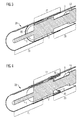
- Figure 3 shows an embodiment of a linear actuator with a telescopic housing 20.
- the telescopic housing 20 comprises an inner telescope part 21, a center telescope part 22 and an outer telescope part 23.
- the profile tube 2 is mounted on its outer side via a bearing 30, a ball bearing for example, on the center telescope part 22, stationarily and rotatably. Thereby the profile tube 2 can rotate inside the surrounding center telescope part 22.
- the center telescope part 22 is connected to the profile tube 2 at the end facing away from the drive unit housing 10.
- the inner telescope part 21 and the outer telescope part 23 are preferably each non-rotatably and longitudinally movably connected to the center telescope part 22.
- the outer end of the threaded spindle 5 and the outer profile tube 23 are preferably non-rotatably connected to one another, for example at one of two parts movable relative to one another. Accordingly the inner telescope part 21 is also non-rotatably connected to the drive unit housing 10. In case of a rotational motion of the driveshaft, there is thus a uniform relative movement of the telescope parts 21, 22, 23 in addition to the relative movement of the parts in the spindle system.
- Figure 4 shows an alternative embodiment of linear actuator in which, following the embodiment illustrated in Figure 3 , the spindle system is arranged in a telescopic housing 20. In the embodiment shown in Figure 4 , however, the arrangement of the telescope parts 21, 22, 23 is interchanged.
- the outer telescope part 23 encloses the drive unit housing 10 and the threaded hollow spindle 3 in the extended state, whereas the inner telescope part 21 encloses the area with the threaded spindle 5.
- the profile tube 2 is connected via a bearing 30, a ball bearing for example, to the center telescope part 22, an extension part 31 being provided between the bearing 30 and the profile tube 2 for construction reasons in the illustrated embodiment.
- the center telescope part 22 is connected to the profile tube 2 at the end facing the drive unit housing 10.
- the threaded spindle 5 is non-rotatably connected to the inner telescope part 21, while the drive unit housing 10 is non-rotatably connected to the outer telescope part 23.
- the profile tube 2 is connected rotatably and stationarily to the center telescope part 22 in both the embodiment shown in Figure 3 and the embodiment shown in Figure 4 .
- This has the effect that a three-part telescopic housing 20 can be flexibly connected in both possible extension directions to the internal spindle system. Thereby the linear actuator can be used more flexibly.
- Figures 5 and 6 show schematic illustrations of embodiments of the linear actuator according to Figures 3 and 4 .
- the embodiment of Figure 5 substantially corresponds to the embodiment of Figure 3
- the embodiment of Figure 6 corresponds substantially to the embodiment of Figure 4 .
- the embodiments of the linear actuator shown in Figures 3 and 5 represent arrangements with a typical extension direction of the telescopic housing 20, while the embodiments shown in Figures 4 and 6 show a so-called upside-down installation of the telescopic housing 20, in which the extension direction of the telescopic drive 20 is reversed.
- a linear actuator according to one of the previously described embodiments is used particularly for adjusting parts movable relative to one another.
- a linear actuator can be used for adjusting the height of a tabletop for a height-adjustable table.
- linear actuators can also be used for other electrically adjustable furniture or for other applications in which linear actuators are typically used.
Landscapes
- Engineering & Computer Science (AREA)
- General Engineering & Computer Science (AREA)
- Mechanical Engineering (AREA)
- Transmission Devices (AREA)
Applications Claiming Priority (1)
| Application Number | Priority Date | Filing Date | Title |
|---|---|---|---|
| DE102012102298.4A DE102012102298B4 (de) | 2012-03-19 | 2012-03-19 | Linearaktuator und höhenverstellbarer Tisch |
Publications (2)
| Publication Number | Publication Date |
|---|---|
| EP2641502A1 true EP2641502A1 (fr) | 2013-09-25 |
| EP2641502B1 EP2641502B1 (fr) | 2016-08-31 |
Family
ID=47877850
Family Applications (1)
| Application Number | Title | Priority Date | Filing Date |
|---|---|---|---|
| EP13158363.5A Active EP2641502B1 (fr) | 2012-03-19 | 2013-03-08 | Actionneur linéaire et table à hauteur réglable |
Country Status (4)
| Country | Link |
|---|---|
| US (1) | US9091334B2 (fr) |
| EP (1) | EP2641502B1 (fr) |
| DE (1) | DE102012102298B4 (fr) |
| DK (1) | DK2641502T3 (fr) |
Cited By (2)
| Publication number | Priority date | Publication date | Assignee | Title |
|---|---|---|---|---|
| WO2018199827A1 (fr) | 2017-04-24 | 2018-11-01 | Kinnarps Ab | Colonne télescopique pour meubles réglables en hauteur |
| WO2019102037A1 (fr) * | 2017-11-27 | 2019-05-31 | Logicdata Electronic & Software Entwicklungs Gmbh | Actionneur linéaire télescopique et table ajustable en hauteur |
Families Citing this family (22)
| Publication number | Priority date | Publication date | Assignee | Title |
|---|---|---|---|---|
| DE102011055045B4 (de) * | 2011-11-04 | 2019-01-17 | Krauss-Maffei Wegmann Gmbh & Co. Kg | Treibladungsportioniereinrichtung |
| US9683643B2 (en) * | 2011-11-21 | 2017-06-20 | Kongsberg Automotive Ab | Linear actuator assembly having a magnetic sensor |
| JP6397425B2 (ja) * | 2012-11-30 | 2018-09-26 | ディー−ボックス テクノロジーズ インコーポレイテッド | 運動シミュレータ用リニアアクチュエータ |
| US9863513B2 (en) * | 2012-11-30 | 2018-01-09 | D-Box Technologies Inc | Linear actuator for motion simulator |
| CN105378341B (zh) | 2012-11-30 | 2018-01-19 | 迪宝克技术公司 | 用于运动模拟器的线性致动器 |
| USD708239S1 (en) * | 2013-10-28 | 2014-07-01 | Timotion Technology Co., Ltd. | Linear actuator |
| TWD176597S (zh) * | 2014-07-16 | 2016-06-21 | 林納克公司 | 線性致動器 |
| TWM491755U (zh) * | 2014-08-18 | 2014-12-11 | Moteck Electric Corp | 具雙螺桿之線性傳動裝置 |
| USD763934S1 (en) * | 2014-09-09 | 2016-08-16 | Linak A/S | Linear dual actuator |
| DE102014117071B4 (de) | 2014-11-21 | 2019-10-31 | Logicdata Electronic & Software Entwicklungs Gmbh | Möbelsystem mit Linearaktuator |
| DE102015104484B4 (de) * | 2015-03-25 | 2016-12-22 | A. Mannesmann Maschinenfabrik Gmbh | Vierstufiger Teleskopaktor mit Gewindetrieb |
| USD765749S1 (en) * | 2015-08-04 | 2016-09-06 | Timotion Technology Co., Ltd. | Linear actuator |
| USD767656S1 (en) * | 2015-08-04 | 2016-09-27 | Timotion Technology Co., Ltd. | Linear actuator |
| USD767005S1 (en) * | 2015-10-16 | 2016-09-20 | Timotion Technology Co., Ltd. | Linear actuator |
| US10436242B2 (en) * | 2016-12-20 | 2019-10-08 | Zhejiang Jiecang Linear Motion Technology Co., Ltd. | Telescopic transmission assembly and lifting column using same |
| DE102018101330A1 (de) * | 2018-01-22 | 2019-07-25 | Logicdata Electronic & Software Entwicklungs Gmbh | Linearaktuator für ein Möbelsystem, elektrisch verstellbares Möbelsystem, Einbauverfahren für einen Linearaktuator in ein Möbelsystem und Möbelsystemanordnung |
| DE102018119426B4 (de) | 2018-08-09 | 2021-05-12 | Logicdata Electronic & Software Entwicklungs Gmbh | Verstellbare Hubsäule und verstellbares Tischsystem |
| WO2021093922A1 (fr) * | 2019-11-13 | 2021-05-20 | Linak A/S | Colonne élévatrice |
| US20230078769A1 (en) * | 2020-05-26 | 2023-03-16 | Sos Solutions, Inc. | Two speed trailer jack |
| US11338777B2 (en) * | 2020-05-26 | 2022-05-24 | Sos Solutions, Inc. | Two speed trailer jack |
| DE102022120890B4 (de) * | 2022-08-18 | 2025-08-28 | Logicdata Electronic & Software Entwicklungs Gmbh | Spindelsystem, linearaktuator und möbelstück |
| DE202024106949U1 (de) | 2024-11-29 | 2026-04-09 | Logicdata Electronic & Software Entwicklungs Gmbh | Körperschallisolator und Linearaktuator mit einem Körperschallisolator |
Citations (4)
| Publication number | Priority date | Publication date | Assignee | Title |
|---|---|---|---|---|
| US3421383A (en) * | 1964-06-11 | 1969-01-14 | Gen Motors Corp | Multiextend screw mechanism |
| US3422696A (en) * | 1964-03-27 | 1969-01-21 | Sargent Eng Corp | Double ball nut and screw actuator |
| DE10058605C1 (de) * | 2000-11-25 | 2002-05-08 | Neuero Technology Gmbh | Hubvorrichtung mit Teleskophubspindel |
| DE20108882U1 (de) * | 2001-05-28 | 2002-10-10 | Flamme, Klaus Peter, Dipl.-Ing., 86916 Kaufering | Doppelspindelmotor |
Family Cites Families (6)
| Publication number | Priority date | Publication date | Assignee | Title |
|---|---|---|---|---|
| US1912230A (en) * | 1932-07-07 | 1933-05-30 | Walker Mfg Co | Stop mechanism for jacks |
| US3404580A (en) * | 1967-04-18 | 1968-10-08 | Sargent Industries | Ball screw actuator |
| US3592070A (en) * | 1969-07-14 | 1971-07-13 | Ivan K Hammond | Linear actuator |
| US3630328A (en) * | 1970-08-24 | 1971-12-28 | Ltv Aerospace Corp | Linear actuator with braking device |
| DE10018742B4 (de) | 2000-04-15 | 2004-09-16 | OKIN Gesellschaft für Antriebstechnik mbH & Co. KG | Vorrichtung zum Verstellen von relativ zueinander beweglichen Teilen |
| DE102008033887B4 (de) * | 2008-07-18 | 2012-02-09 | weiss Präzisionstechnik GmbH & Co. KG | Teleskop-Doppelspindelantrieb |
-
2012
- 2012-03-19 DE DE102012102298.4A patent/DE102012102298B4/de not_active Expired - Fee Related
-
2013
- 2013-03-08 EP EP13158363.5A patent/EP2641502B1/fr active Active
- 2013-03-08 DK DK13158363.5T patent/DK2641502T3/en active
- 2013-03-14 US US13/831,319 patent/US9091334B2/en active Active
Patent Citations (4)
| Publication number | Priority date | Publication date | Assignee | Title |
|---|---|---|---|---|
| US3422696A (en) * | 1964-03-27 | 1969-01-21 | Sargent Eng Corp | Double ball nut and screw actuator |
| US3421383A (en) * | 1964-06-11 | 1969-01-14 | Gen Motors Corp | Multiextend screw mechanism |
| DE10058605C1 (de) * | 2000-11-25 | 2002-05-08 | Neuero Technology Gmbh | Hubvorrichtung mit Teleskophubspindel |
| DE20108882U1 (de) * | 2001-05-28 | 2002-10-10 | Flamme, Klaus Peter, Dipl.-Ing., 86916 Kaufering | Doppelspindelmotor |
Cited By (2)
| Publication number | Priority date | Publication date | Assignee | Title |
|---|---|---|---|---|
| WO2018199827A1 (fr) | 2017-04-24 | 2018-11-01 | Kinnarps Ab | Colonne télescopique pour meubles réglables en hauteur |
| WO2019102037A1 (fr) * | 2017-11-27 | 2019-05-31 | Logicdata Electronic & Software Entwicklungs Gmbh | Actionneur linéaire télescopique et table ajustable en hauteur |
Also Published As
| Publication number | Publication date |
|---|---|
| US9091334B2 (en) | 2015-07-28 |
| DE102012102298B4 (de) | 2015-10-29 |
| US20140013878A1 (en) | 2014-01-16 |
| DK2641502T3 (en) | 2016-12-19 |
| DE102012102298A1 (de) | 2013-09-19 |
| EP2641502B1 (fr) | 2016-08-31 |
Similar Documents
| Publication | Publication Date | Title |
|---|---|---|
| US9091334B2 (en) | Linear actuator and height-adjustable table | |
| US5809833A (en) | Linear actuator | |
| EP2290260B1 (fr) | Actionneur linéaire comprenant un système de détection de position de butée | |
| US8342465B2 (en) | Height adjustable column, in particular for tables | |
| US9797491B2 (en) | Electric actuator assembly | |
| EP2342992A1 (fr) | Actionneur linéaire pour colonnes à hauteur réglable | |
| EP2301382A1 (fr) | Colonne télescopique pour le réglage de la hauteur | |
| US20180031091A1 (en) | Miniature linear actuator | |
| JP2018511754A (ja) | ねじ駆動機構を備える4段テレスコープ式アクチュエーター | |
| AU2006215577A1 (en) | Electromotive linear drive | |
| US5121019A (en) | Rotary to linear drive unit | |
| EP1881235A2 (fr) | Entraînement à broche pouvant être actionné par un engrenage pour composant mobile | |
| EP3710290B1 (fr) | Unité d'amortisseur et ressort pour une suspension de véhicule et dispositif de réglage electro-mecanique pour ajuster la position verticale du ressort | |
| US20080276537A1 (en) | Liftgate drive unit | |
| US20100140573A1 (en) | Lifting device | |
| JP2022061496A (ja) | 家具用昇降支柱 | |
| CN114641421A (zh) | 用于机动车辆的转向装置的反馈致动器 | |
| US20210112970A1 (en) | Telescopic linear actuator and height adjustable table | |
| US9735657B2 (en) | Actuator | |
| CN106122407B (zh) | 螺纹传动组件和具有螺纹传动组件的座位组件 | |
| US8881613B2 (en) | Electric actuator and manual adjustment mechanism thereof | |
| KR20160006135A (ko) | 전동 실린더 | |
| EP3614884B1 (fr) | Colonne télescopique pour meubles réglables en hauteur | |
| DE102004054037B3 (de) | Verstellvorrichtung | |
| JP5921384B2 (ja) | 直線作動機 |
Legal Events
| Date | Code | Title | Description |
|---|---|---|---|
| PUAI | Public reference made under article 153(3) epc to a published international application that has entered the european phase |
Free format text: ORIGINAL CODE: 0009012 |
|
| AK | Designated contracting states |
Kind code of ref document: A1 Designated state(s): AL AT BE BG CH CY CZ DE DK EE ES FI FR GB GR HR HU IE IS IT LI LT LU LV MC MK MT NL NO PL PT RO RS SE SI SK SM TR |
|
| AX | Request for extension of the european patent |
Extension state: BA ME |
|
| 17P | Request for examination filed |
Effective date: 20140324 |
|
| RBV | Designated contracting states (corrected) |
Designated state(s): AL AT BE BG CH CY CZ DE DK EE ES FI FR GB GR HR HU IE IS IT LI LT LU LV MC MK MT NL NO PL PT RO RS SE SI SK SM TR |
|
| GRAP | Despatch of communication of intention to grant a patent |
Free format text: ORIGINAL CODE: EPIDOSNIGR1 |
|
| INTG | Intention to grant announced |
Effective date: 20160415 |
|
| RAP1 | Party data changed (applicant data changed or rights of an application transferred) |
Owner name: LOGICDATA ELECTRONIC & SOFTWARE ENTWICKLUNGS GMBH |
|
| GRAS | Grant fee paid |
Free format text: ORIGINAL CODE: EPIDOSNIGR3 |
|
| GRAA | (expected) grant |
Free format text: ORIGINAL CODE: 0009210 |
|
| AK | Designated contracting states |
Kind code of ref document: B1 Designated state(s): AL AT BE BG CH CY CZ DE DK EE ES FI FR GB GR HR HU IE IS IT LI LT LU LV MC MK MT NL NO PL PT RO RS SE SI SK SM TR |
|
| REG | Reference to a national code |
Ref country code: CH Ref legal event code: EP Ref country code: GB Ref legal event code: FG4D |
|
| REG | Reference to a national code |
Ref country code: IE Ref legal event code: FG4D |
|
| REG | Reference to a national code |
Ref country code: DE Ref legal event code: R096 Ref document number: 602013010822 Country of ref document: DE |
|
| REG | Reference to a national code |
Ref country code: CH Ref legal event code: NV Representative=s name: PATENTANWALTSKANZLEI NUECKEL, CH |
|
| REG | Reference to a national code |
Ref country code: AT Ref legal event code: REF Ref document number: 824162 Country of ref document: AT Kind code of ref document: T Effective date: 20161015 |
|
| REG | Reference to a national code |
Ref country code: SE Ref legal event code: TRGR |
|
| REG | Reference to a national code |
Ref country code: NL Ref legal event code: FP |
|
| REG | Reference to a national code |
Ref country code: DK Ref legal event code: T3 Effective date: 20161218 |
|
| REG | Reference to a national code |
Ref country code: LT Ref legal event code: MG4D |
|
| REG | Reference to a national code |
Ref country code: AT Ref legal event code: MK05 Ref document number: 824162 Country of ref document: AT Kind code of ref document: T Effective date: 20160831 |
|
| PG25 | Lapsed in a contracting state [announced via postgrant information from national office to epo] |
Ref country code: LT Free format text: LAPSE BECAUSE OF FAILURE TO SUBMIT A TRANSLATION OF THE DESCRIPTION OR TO PAY THE FEE WITHIN THE PRESCRIBED TIME-LIMIT Effective date: 20160831 Ref country code: RS Free format text: LAPSE BECAUSE OF FAILURE TO SUBMIT A TRANSLATION OF THE DESCRIPTION OR TO PAY THE FEE WITHIN THE PRESCRIBED TIME-LIMIT Effective date: 20160831 Ref country code: NO Free format text: LAPSE BECAUSE OF FAILURE TO SUBMIT A TRANSLATION OF THE DESCRIPTION OR TO PAY THE FEE WITHIN THE PRESCRIBED TIME-LIMIT Effective date: 20161130 Ref country code: HR Free format text: LAPSE BECAUSE OF FAILURE TO SUBMIT A TRANSLATION OF THE DESCRIPTION OR TO PAY THE FEE WITHIN THE PRESCRIBED TIME-LIMIT Effective date: 20160831 |
|
| PG25 | Lapsed in a contracting state [announced via postgrant information from national office to epo] |
Ref country code: ES Free format text: LAPSE BECAUSE OF FAILURE TO SUBMIT A TRANSLATION OF THE DESCRIPTION OR TO PAY THE FEE WITHIN THE PRESCRIBED TIME-LIMIT Effective date: 20160831 Ref country code: GR Free format text: LAPSE BECAUSE OF FAILURE TO SUBMIT A TRANSLATION OF THE DESCRIPTION OR TO PAY THE FEE WITHIN THE PRESCRIBED TIME-LIMIT Effective date: 20161201 Ref country code: LV Free format text: LAPSE BECAUSE OF FAILURE TO SUBMIT A TRANSLATION OF THE DESCRIPTION OR TO PAY THE FEE WITHIN THE PRESCRIBED TIME-LIMIT Effective date: 20160831 Ref country code: AT Free format text: LAPSE BECAUSE OF FAILURE TO SUBMIT A TRANSLATION OF THE DESCRIPTION OR TO PAY THE FEE WITHIN THE PRESCRIBED TIME-LIMIT Effective date: 20160831 |
|
| REG | Reference to a national code |
Ref country code: FR Ref legal event code: PLFP Year of fee payment: 5 |
|
| PG25 | Lapsed in a contracting state [announced via postgrant information from national office to epo] |
Ref country code: RO Free format text: LAPSE BECAUSE OF FAILURE TO SUBMIT A TRANSLATION OF THE DESCRIPTION OR TO PAY THE FEE WITHIN THE PRESCRIBED TIME-LIMIT Effective date: 20160831 Ref country code: EE Free format text: LAPSE BECAUSE OF FAILURE TO SUBMIT A TRANSLATION OF THE DESCRIPTION OR TO PAY THE FEE WITHIN THE PRESCRIBED TIME-LIMIT Effective date: 20160831 |
|
| PG25 | Lapsed in a contracting state [announced via postgrant information from national office to epo] |
Ref country code: PL Free format text: LAPSE BECAUSE OF FAILURE TO SUBMIT A TRANSLATION OF THE DESCRIPTION OR TO PAY THE FEE WITHIN THE PRESCRIBED TIME-LIMIT Effective date: 20160831 Ref country code: SM Free format text: LAPSE BECAUSE OF FAILURE TO SUBMIT A TRANSLATION OF THE DESCRIPTION OR TO PAY THE FEE WITHIN THE PRESCRIBED TIME-LIMIT Effective date: 20160831 Ref country code: CZ Free format text: LAPSE BECAUSE OF FAILURE TO SUBMIT A TRANSLATION OF THE DESCRIPTION OR TO PAY THE FEE WITHIN THE PRESCRIBED TIME-LIMIT Effective date: 20160831 Ref country code: BE Free format text: LAPSE BECAUSE OF FAILURE TO SUBMIT A TRANSLATION OF THE DESCRIPTION OR TO PAY THE FEE WITHIN THE PRESCRIBED TIME-LIMIT Effective date: 20160831 Ref country code: PT Free format text: LAPSE BECAUSE OF FAILURE TO SUBMIT A TRANSLATION OF THE DESCRIPTION OR TO PAY THE FEE WITHIN THE PRESCRIBED TIME-LIMIT Effective date: 20170102 Ref country code: BG Free format text: LAPSE BECAUSE OF FAILURE TO SUBMIT A TRANSLATION OF THE DESCRIPTION OR TO PAY THE FEE WITHIN THE PRESCRIBED TIME-LIMIT Effective date: 20161130 Ref country code: SK Free format text: LAPSE BECAUSE OF FAILURE TO SUBMIT A TRANSLATION OF THE DESCRIPTION OR TO PAY THE FEE WITHIN THE PRESCRIBED TIME-LIMIT Effective date: 20160831 |
|
| REG | Reference to a national code |
Ref country code: DE Ref legal event code: R097 Ref document number: 602013010822 Country of ref document: DE |
|
| PG25 | Lapsed in a contracting state [announced via postgrant information from national office to epo] |
Ref country code: IT Free format text: LAPSE BECAUSE OF FAILURE TO SUBMIT A TRANSLATION OF THE DESCRIPTION OR TO PAY THE FEE WITHIN THE PRESCRIBED TIME-LIMIT Effective date: 20160831 |
|
| PLBE | No opposition filed within time limit |
Free format text: ORIGINAL CODE: 0009261 |
|
| STAA | Information on the status of an ep patent application or granted ep patent |
Free format text: STATUS: NO OPPOSITION FILED WITHIN TIME LIMIT |
|
| 26N | No opposition filed |
Effective date: 20170601 |
|
| PG25 | Lapsed in a contracting state [announced via postgrant information from national office to epo] |
Ref country code: SI Free format text: LAPSE BECAUSE OF FAILURE TO SUBMIT A TRANSLATION OF THE DESCRIPTION OR TO PAY THE FEE WITHIN THE PRESCRIBED TIME-LIMIT Effective date: 20160831 |
|
| PG25 | Lapsed in a contracting state [announced via postgrant information from national office to epo] |
Ref country code: MC Free format text: LAPSE BECAUSE OF FAILURE TO SUBMIT A TRANSLATION OF THE DESCRIPTION OR TO PAY THE FEE WITHIN THE PRESCRIBED TIME-LIMIT Effective date: 20160831 |
|
| REG | Reference to a national code |
Ref country code: IE Ref legal event code: MM4A |
|
| PG25 | Lapsed in a contracting state [announced via postgrant information from national office to epo] |
Ref country code: LU Free format text: LAPSE BECAUSE OF NON-PAYMENT OF DUE FEES Effective date: 20170308 |
|
| REG | Reference to a national code |
Ref country code: CH Ref legal event code: PCAR Free format text: NEW ADDRESS: OBERDORFSTRASSE 16, 8820 WAEDENSWIL (CH) |
|
| PG25 | Lapsed in a contracting state [announced via postgrant information from national office to epo] |
Ref country code: IE Free format text: LAPSE BECAUSE OF NON-PAYMENT OF DUE FEES Effective date: 20170308 |
|
| REG | Reference to a national code |
Ref country code: FR Ref legal event code: PLFP Year of fee payment: 6 |
|
| PG25 | Lapsed in a contracting state [announced via postgrant information from national office to epo] |
Ref country code: MT Free format text: LAPSE BECAUSE OF NON-PAYMENT OF DUE FEES Effective date: 20170308 |
|
| PG25 | Lapsed in a contracting state [announced via postgrant information from national office to epo] |
Ref country code: AL Free format text: LAPSE BECAUSE OF FAILURE TO SUBMIT A TRANSLATION OF THE DESCRIPTION OR TO PAY THE FEE WITHIN THE PRESCRIBED TIME-LIMIT Effective date: 20160831 |
|
| PGFP | Annual fee paid to national office [announced via postgrant information from national office to epo] |
Ref country code: CH Payment date: 20190325 Year of fee payment: 7 Ref country code: GB Payment date: 20190325 Year of fee payment: 7 Ref country code: FR Payment date: 20190326 Year of fee payment: 7 |
|
| PG25 | Lapsed in a contracting state [announced via postgrant information from national office to epo] |
Ref country code: HU Free format text: LAPSE BECAUSE OF FAILURE TO SUBMIT A TRANSLATION OF THE DESCRIPTION OR TO PAY THE FEE WITHIN THE PRESCRIBED TIME-LIMIT; INVALID AB INITIO Effective date: 20130308 |
|
| PG25 | Lapsed in a contracting state [announced via postgrant information from national office to epo] |
Ref country code: CY Free format text: LAPSE BECAUSE OF NON-PAYMENT OF DUE FEES Effective date: 20160831 |
|
| PG25 | Lapsed in a contracting state [announced via postgrant information from national office to epo] |
Ref country code: MK Free format text: LAPSE BECAUSE OF FAILURE TO SUBMIT A TRANSLATION OF THE DESCRIPTION OR TO PAY THE FEE WITHIN THE PRESCRIBED TIME-LIMIT Effective date: 20160831 |
|
| PG25 | Lapsed in a contracting state [announced via postgrant information from national office to epo] |
Ref country code: TR Free format text: LAPSE BECAUSE OF FAILURE TO SUBMIT A TRANSLATION OF THE DESCRIPTION OR TO PAY THE FEE WITHIN THE PRESCRIBED TIME-LIMIT Effective date: 20160831 |
|
| PG25 | Lapsed in a contracting state [announced via postgrant information from national office to epo] |
Ref country code: IS Free format text: LAPSE BECAUSE OF FAILURE TO SUBMIT A TRANSLATION OF THE DESCRIPTION OR TO PAY THE FEE WITHIN THE PRESCRIBED TIME-LIMIT Effective date: 20161231 |
|
| REG | Reference to a national code |
Ref country code: CH Ref legal event code: PL |
|
| PG25 | Lapsed in a contracting state [announced via postgrant information from national office to epo] |
Ref country code: LI Free format text: LAPSE BECAUSE OF NON-PAYMENT OF DUE FEES Effective date: 20200331 Ref country code: CH Free format text: LAPSE BECAUSE OF NON-PAYMENT OF DUE FEES Effective date: 20200331 |
|
| GBPC | Gb: european patent ceased through non-payment of renewal fee |
Effective date: 20200308 |
|
| PG25 | Lapsed in a contracting state [announced via postgrant information from national office to epo] |
Ref country code: GB Free format text: LAPSE BECAUSE OF NON-PAYMENT OF DUE FEES Effective date: 20200308 |
|
| PGFP | Annual fee paid to national office [announced via postgrant information from national office to epo] |
Ref country code: NL Payment date: 20210319 Year of fee payment: 9 Ref country code: FI Payment date: 20210318 Year of fee payment: 9 |
|
| PGFP | Annual fee paid to national office [announced via postgrant information from national office to epo] |
Ref country code: SE Payment date: 20220324 Year of fee payment: 10 |
|
| PG25 | Lapsed in a contracting state [announced via postgrant information from national office to epo] |
Ref country code: FR Free format text: LAPSE BECAUSE OF NON-PAYMENT OF DUE FEES Effective date: 20200331 |
|
| REG | Reference to a national code |
Ref country code: FI Ref legal event code: MAE |
|
| PG25 | Lapsed in a contracting state [announced via postgrant information from national office to epo] |
Ref country code: FI Free format text: LAPSE BECAUSE OF NON-PAYMENT OF DUE FEES Effective date: 20220308 |
|
| REG | Reference to a national code |
Ref country code: NL Ref legal event code: MM Effective date: 20220401 |
|
| PG25 | Lapsed in a contracting state [announced via postgrant information from national office to epo] |
Ref country code: NL Free format text: LAPSE BECAUSE OF NON-PAYMENT OF DUE FEES Effective date: 20220401 |
|
| REG | Reference to a national code |
Ref country code: SE Ref legal event code: EUG |
|
| PG25 | Lapsed in a contracting state [announced via postgrant information from national office to epo] |
Ref country code: SE Free format text: LAPSE BECAUSE OF NON-PAYMENT OF DUE FEES Effective date: 20230309 |
|
| PGFP | Annual fee paid to national office [announced via postgrant information from national office to epo] |
Ref country code: DK Payment date: 20260323 Year of fee payment: 14 Ref country code: DE Payment date: 20260325 Year of fee payment: 14 |