EP2641575B1 - Fahrzeuglift mit Vorspanneinrichtung - Google Patents
Fahrzeuglift mit Vorspanneinrichtung Download PDFInfo
- Publication number
- EP2641575B1 EP2641575B1 EP20130160447 EP13160447A EP2641575B1 EP 2641575 B1 EP2641575 B1 EP 2641575B1 EP 20130160447 EP20130160447 EP 20130160447 EP 13160447 A EP13160447 A EP 13160447A EP 2641575 B1 EP2641575 B1 EP 2641575B1
- Authority
- EP
- European Patent Office
- Prior art keywords
- platform
- vehicle lift
- support
- spring
- support pillar
- Prior art date
- Legal status (The legal status is an assumption and is not a legal conclusion. Google has not performed a legal analysis and makes no representation as to the accuracy of the status listed.)
- Active
Links
Images




Classifications
-
- A—HUMAN NECESSITIES
- A61—MEDICAL OR VETERINARY SCIENCE; HYGIENE
- A61G—TRANSPORT, PERSONAL CONVEYANCES, OR ACCOMMODATION SPECIALLY ADAPTED FOR PATIENTS OR DISABLED PERSONS; OPERATING TABLES OR CHAIRS; CHAIRS FOR DENTISTRY; FUNERAL DEVICES
- A61G3/00—Ambulance aspects of vehicles; Vehicles with special provisions for transporting patients or disabled persons, or their personal conveyances, e.g. for facilitating access of, or for loading, wheelchairs
- A61G3/02—Loading or unloading personal conveyances; Facilitating access of patients or disabled persons to, or exit from, vehicles
- A61G3/06—Transfer using ramps, lifts or the like
- A61G3/062—Transfer using ramps, lifts or the like using lifts connected to the vehicle
-
- F—MECHANICAL ENGINEERING; LIGHTING; HEATING; WEAPONS; BLASTING
- F04—POSITIVE - DISPLACEMENT MACHINES FOR LIQUIDS; PUMPS FOR LIQUIDS OR ELASTIC FLUIDS
- F04C—ROTARY-PISTON, OR OSCILLATING-PISTON, POSITIVE-DISPLACEMENT MACHINES FOR LIQUIDS; ROTARY-PISTON, OR OSCILLATING-PISTON, POSITIVE-DISPLACEMENT PUMPS
- F04C2270/00—Control; Monitoring or safety arrangements
- F04C2270/04—Force
- F04C2270/042—Force radial
- F04C2270/0421—Controlled or regulated
Definitions
- the invention relates to a vehicle lift for loads, in particular wheelchairs, which is at least in a first, retracted position and a second extended position, with at least one support spar, a platform which is hinged about a horizontal pivot axis pivotally mounted on the at least one support beam, and at least one lifting device articulated to the support beam for raising and lowering the support beam together with the platform.
- Vehicle-mounted vehicle lifts have long been known. They serve to convey objects or persons from the interior of the vehicle to the outside and back, when there is a height difference or a gap must be bridged between the level of the vehicle interior and the place to which the objects or persons are to be brought.
- An important application find such vehicle lifts in vehicles where wheelchair users are transported.
- Such a generic vehicle lift the local applicant is, for example, in DE 203 09 868 U 1 disclosed.
- Known vehicle lifts have a platform which is movably articulated on the at least one support beam and is moved by means of a lifting device.
- a lifting device As a rule, at least two main positions can be distinguished. The first position is the retracted position during which the vehicle lift is not used. The platform is then usually in a vertical position, so that the entire vehicle lift has the smallest possible space and space requirements and does not bother while driving the vehicle.
- the vehicle lift In the second position, the vehicle lift is extended and the platform is located substantially horizontally near the ground so that, for example, a wheelchair user can easily ride off the ground onto the platform.
- an intermediate position is provided, in which the platform is approximately at the level of a vehicle interior, so that, for example, a wheelchair user can drive from the platform into the vehicle interior.
- the platform is lowered substantially parallel to itself by means of the lifting device.
- the platform has to be moved from the vertical to the horizontal position; on the other hand, it has to be lowered to a floor level so that, for example, wheelchair users can drive it easily.
- the lifting devices that are used to apply sufficient power to raise even heavier loads by means of the vehicle lift, but still as small as possible, so that on the one hand, the weight and the power consumption of the vehicle lift is low.
- a critical point here is the start when spending from the retracted to the extended position.
- Object of the present invention is therefore to provide a vehicle lift of the type mentioned, which is improved with respect to at least one of the above problems.
- the invention solves the problem in a vehicle lift of the type mentioned by the means of the first claim, in particular by providing a torsion bar having biasing means for biasing the vehicle lift in the second position, in the region of the articulated connection between the platform and supporting spar attacks.
- the invention is based on the recognition that in particular the starting point when moving from the first to the second position of the vehicle lift is critical. Further, the invention is based on the recognition that it is not necessary to fully support the movement in the movement from the first to the second position, but that it is sufficient to support only a certain range. It has proven to be particularly efficient when the pretensioner engages the articulated connection between the platform and the carrier spar.
- the biasing means which is arranged for biasing the vehicle lift in the second position, thus biases the platform so that it automatically at least at a certain pivot angle from the first position in which the platform is arranged substantially vertically, in the direction of the second Position in which the platform is arranged substantially horizontally under, is biased.
- the platform, supported by the bias already moved a bit from the first to the second position, the rest of the movement can be done solely by the weight of the platform. Consequently, it is possible to make the pretensioner much smaller, which also reduces the weight of the vehicle lift. Furthermore, the fact that the biasing device engages in the region of the articulated connection between the platform and the carrier spar substantially simplifies the maintenance.
- the biasing device has at least one spring element.
- Spring elements are simple components that require no additional energy and low maintenance.
- the at least one spring element is designed as a torsion spring.
- a torsion spring can be used advantageously as a biasing device, since the biasing device engages in the region of the articulated connection between the platform and the carrier spar.
- This compound is preferably as a pivotal connection designed so that the use of torsion springs is particularly preferred.
- other tension or compression springs could be used.
- the construction is substantially simplified when torsion springs are used.
- Such a torsion spring is preferably designed as a leg spring. In this case, preferably attacks a first leg on the support beam and a second leg on the platform, so that the energy stored in the torsion spring can be used in the form of moments for biasing the vehicle lift in the second position.
- the torsion spring is designed as a torsion bar. Torsion springs are less susceptible to failure than coil springs due to their significantly lower or eliminated flexing stress. As a result, maintenance intervals can be selected longer, making maintenance much easier. Furthermore torsion bar springs can save more energy than coil springs with a corresponding design in a compact design, whereby the construction is simplified and weight can be saved.
- the torsion bar spring has a spring body and two legs extending from the spring body for introducing moments into the spring body. Through the two legs can be initiated in a simple way moments in the spring body. Special fixtures are eliminated.
- the spring member engages a first portion with the support spar and with a second portion with the platform in engagement.
- the first leg engages the carrier spar and the second leg engages the platform. This allows the moments to initiate particularly effectively and the pretensioner is designed to be efficient and low maintenance.
- the spring body is arranged substantially in a plane of the platform. So a particularly space-saving arrangement is achieved.
- the spring body extends substantially over its entire length along the platform.
- the spring body extends substantially parallel to the pivot axis of the platform along this.
- the Spring body arranged at the bottom of the platform.
- the term underside refers to the side of the platform which, in the second position, preferably rests on a floor or is executed thereon.
- the torsion spring is not applied to the area of the platform, which is traveled by, for example, a wheelchair user and thus does not bother.
- the torsion spring is accessible in a simple manner when the vehicle lift is in the first position. As a result, on the one hand, the construction of the vehicle lift compact possible on the other hand, the maintenance is much easier.
- the vehicle lift has two support struts, which are articulated to the platform in each case in an articulated manner
- the pretensioning device has two spring elements.
- a first spring element cooperates with the first carrier spar and a second spring element with the second carrier spar.
- both spring elements are designed as torsion bar springs and extend with their spring bodies on the underside of the platform.
- the lifting device has a parallelogram linkage with at least two substantially parallel to each other arranged support arms, which are articulated in each case with one end to the support beam and the other end to a vehicle-side attachment portion.
- a parallelogram linkage is basically, for example, in the aforementioned DE 203 09 868 U1 discloses and can be used advantageously for moving the vehicle lift. If two supporting beams are provided, preferably two parallelogram linkages are also provided.
- other lifting devices such as purely hydraulic, pneumatic, electrical or other mechanical lifting devices, such as various cables and the like could be used.
- the at least one support spar and / or the support arms are formed as aluminum profiles.
- the support beam and / or the support arms are formed as aluminum profiles, no welds or other joining process steps are necessary.
- the spar is bent Aluminum profile formed.
- the at least one support spar and / or the support arms are formed completely in one piece.
- the production is much easier, on the other hand eliminates critical joints, whereby the life and safety of the vehicle lift is improved.
- the weight of the vehicle lift is significantly reduced.
- the visual impression of the supporting beam and thus the entire vehicle lift is significantly improved. It arises a gently curved, pleasing and sporty impression, which is caused by the integral curved construction of the supporting beam.
- the at least one carrier beam is designed as a carrier beam which is bent in one piece, any other material, such as steel, is also preferred, even if aluminum is particularly preferred, also with regard to a weight saving.
- a mechanism for pivoting the platform which acts on the platform.
- the mechanism is intended to pivot the platform from the first, retracted position, in which the platform is oriented substantially vertically, to the horizontal, in which the platform is located in the second, extended position.
- This pivoting movement is supported according to the invention in a first pivoting portion of the biasing device. Consequently, the lifting device is provided for raising and lowering, and the mechanism only for pivoting the platform.
- this mechanism for pivoting the platform on a toggle lever with a first leg and a second leg connected thereto kniegelenkig, wherein the first leg is hinged to the support beam and the second leg to the platform.
- a toggle is a particularly easy way to pivot the platform.
- the knee joint on which a sliding shoe is preferably provided can come into contact with one of the support arms of the parallelogram linkage and thus pivot the platform.
- the second leg is designed as a push rod, wherein at both ends hinge elements are arranged relative to the push rod adjustable.
- the hinge elements wherein a hinge member forms with a part of the knee joint and the second hinge member is hinged to the platform and / or on the support, connected by means of opposing threads with the push rod.
- the two joint elements about each other by turning the push rod to move away from each other and so relative to each other adjustable.
- a pivot angle of the platform when moving from the first position to the second position is adjustable. Depending on the vehicle type and installation situation, this angle can vary, so that it is advantageous to make this angle adjustable in a simple manner.
- two side plates are arranged on the platform, each having an embossment.
- Side panels serve on the one hand for the lateral guidance of, for example, on the platform moving wheelchairs and so on the one hand increase security. On the other hand, they also serve to stabilize the platform, so that it does not bend under load.
- the side plates are for this purpose preferably arranged substantially perpendicular to the plane formed by the platform.
- At least one support for supporting moments against the support spar is arranged on the platform. Moments caused by loads on the platform around the hinged connection between platform and spar must be supported.
- the support is preferably fixedly attached to the platform and has a contact portion with which it comes into contact with the carrier beam so as to support moments against it.
- the support is preferably designed as a free-form and / or cast part. This also reduces the weight of the vehicle lift.
- the support is intended to limit a pivoting movement of the platform relative to the support beam by a stop formed on the support comes into contact with the support beam, wherein the force is introduced into the support beam in a central region of the support beam, preferably substantially centered a direction perpendicular to the longitudinal axis of the support beam takes place.
- the introduction of force takes place in the region of a spine of the carrier beam, which is substantially U-shaped in cross-section, preferably between the two legs of the U-shaped carrier spar and not on one of the legs.
- a Tordieren the support beam avoided.
- the stop of the support is preferably formed on a projection which extends from the platform arm-shaped in the direction of the supporting beam.
- a reinforcing profile for cooperation with the stop of the support is arranged on the carrier beam.
- the support rail is formed of aluminum.
- Aluminum is a lightweight material with a low density. Due to these properties, impact and abrasion stresses can sometimes lead to faster wear. Therefore, this reinforcement profile is preferably arranged on the support beam to protect the material.
- the reinforcing profile can be arranged internally, for example, in the U-shaped region of the supporting beam.
- the reinforcing profile is connected by means of a screw connection with the carrier spar.
- the reinforcing profile is preferably provided as a wearing part. Thus, in the case of wear alone, replace the reinforcing profile, while the spar remains intact.
- the reinforcing profile is also preferably made of aluminum.
- the reinforcing profile is made of another metal or plastic material.
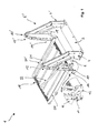
- a vehicle lift 1 is shown in perspective in a position referred to above as an intermediate position.
- two mutually mirror-symmetrical stand 4, 4 ' are fixed.
- the bottom plate 2 and the stand 4, 4 ' together form a vehicle-side holding section.
- a lifting device 6, 6' is arranged, which is formed according to this embodiment as a parallelogram linkage.
- a support beam 10, 10 ' is at the opposite end of the uprights 4, 4'.
- the support beam 10, 10 ' has an upper portion 12, 12' and a lower portion 14, 14 '.
- a platform 16 pivotally connected by a shaft 19 about the pivot axis 18.
- a biasing device 100 is provided which engages in the region of the articulated connection between the platform 16 and supporting bars 10, 10 '.
- the biasing device 100 is below, in particular with respect to the FIGS. 4 to 9 explained in more detail.
- the support beam 10, 10 ' is in one piece and formed in the upper portion 12, 12 'bent along its longitudinal axis.
- the support beam 10, 10 ' is formed as an aluminum profile with a substantially U-shaped cross-section.
- the lifting device 6, 6 ' (see FIG. 2 ) is designed as a parallelogram linkage. It has a first support arm 24 and a second support arm 26 arranged parallel thereto. Both support arms 24, 26 are connected to both the stator 4, and with the support beam 10 by means of the articulation points 30, 31, 32, 33 articulated. All articulation points 30, 31, 32, 33 are formed as pin connectors, wherein at the articulation points 32, 33, which are arranged in the support beam 10, in addition not shown bushes are introduced into the holes on the support beam 10 to wear on the support beam 10 to prevent.
- the two support arms 24, 26 are the same length and formed substantially identical.
- the articulation points 30, 31 on the stand 4 are selected such that the support arms 24, 26 forming the parallelogram can be brought into a first retracted position, in which the two support arms 24, 26 are arranged substantially vertically (cf. FIG. 4 ) and in a (not shown here) second position in which the support arms 24, 26 are arranged substantially horizontally.
- the articulation points 32, 33 on the support beam 10 are arranged correspondingly offset so as to allow the parallelogram of the lifting device 6.
- the upper portion 12 of the support beam 10 is formed bent so that the offset between the articulation points 32 and 33 is compensated.
- the lower portion 14 of the support beam 10 is formed substantially straight. This enables a compact design that also saves weight.
- a hydraulic cylinder 28 is provided for driving the lifting device 6.
- the hydraulic cylinder 28 is arranged diagonally in the parallelogram formed by the support arms 24, 26.
- the hydraulic cylinder 28 is connected on the one hand to the articulation point 30 and on the other hand to the articulation point 33.
- a mechanism 34 for pivoting the platform 16 is arranged on the vehicle lift 1.
- the mechanism 34 has a first leg 38, which is articulated to the carrier spar 10 and a second leg 36, which by means of a hinge 40 is connected to the first leg 38.
- a slide shoe 37 is further arranged.
- the other end of the second leg 36 cooperates with the platform 16.
- a support 42 for supporting moments against the carrier spar 10 is arranged on the platform 16.
- the second leg 36 engages by being connected by means of a hinge 44 with this articulated.
- FIG. 2 As can be seen, the slide shoe 37 comes into contact with the second support arm 26 when the vehicle lift is moved to the first retracted position. In this case, a force acting on the second leg 36 on the support 42 and so on the platform 16, that it is pivoted about the pivot axis 18 around in the vertical. On the other hand, when extending the vehicle lift 1, the shoe 37 loses from a certain extension point (for example, from the intermediate position as in FIG.
- an arm-shaped projection 48 is arranged on the support 42, which serves as a stop and a pivotal movement of the platform 16 relative to the support beam 10 limited by the projection 48 comes into contact with a reinforcing profile 50 (see FIG. 3 ).
- a screw 49 is arranged on the projection 48, which serves as an adjustable stop.
- the reinforcing profile 50 is screwed by means of two screw 51, 52 with the support beam 10.
- the shaft 19 which defines the pivot axis 18 is also received in the reinforcing profile 50 and firmly clamped in this with a clamping 54.
- the shaft 19 has a flattened region, so that the reinforcing profile 50 can engage in a positive engagement therewith.
- the first leg 38 of the mechanism 34 extends through the support spar 10, beyond the pivot bearing 45 addition.
- the support spar 10 also extending portion 39 of the handle 22 is attached. So this is when moving from the first to the second or from the second to the first position of the vehicle lift 1 automatically with movable and is pivoted in the first position vertically upwards.
- the handle 22 By the handle 22, the in FIG. 3 has curved shape shown, this fits essentially to the curved Section 12 of the support beam 10 at. As a result, the vehicle lift 1 is particularly space-saving.
- FIG. 4 which illustrates the first position of the vehicle lift 1
- a side plate 60 is additionally arranged laterally on the lifting device 6. This serves on the one hand to reduce a risk of injury by preventing, for example, operators with fingers between the support arms 24, 26 advised.
- the side plate 60 has optical reasons. For illustration purposes it is related to FIG. 4 left carrier spar 10 'omitted, so that the support arms 24', 26 'are visible. Only the right support beam 10 is shown.
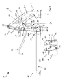
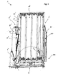
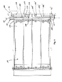
- the biasing means 100 comprises two symmetrically formed torsion bar springs 102, 102 '(in FIG Fig. 5 only one shown), each extending at the bottom of the platform 16 (see in particular Fig. 6 ).
- the biasing device 100 is provided to pivot the connection between the platform 16 and the support bars 10, 10 'about the pivot axis 18 in the in Fig. 5 to bias shown second position.
- Each torsion bar spring 102, 102 ' has a spring body 106, 106 'and two of the spring body 106, 106' extending leg 104, 104 ', 108, 108' on.
- the torsion bar springs 102, 102 ' are disposed on the underside of the platform 116 so as to occupy approximately half the width of the platform 16, respectively.
- the first leg 104, 104 ' cooperates with the platform 16 for pretensioning with the carrier spar 10, 10' and the second leg 108, 108 '.
- each support 42, 42 ' has a through hole 41, 41', through which the first leg 104, 104 'of the torsion bar spring 102, 102' extends, so as to engage with the stop 11, 11 'of the support bars 10, 10' in FIG To come in contact.
- the at the opposite end of the spring body 106, 106 'formed second leg 108, 108' of the torsion bar spring 102, 102 ' is fixedly connected to the platform 16.
- the first leg 104, 104 'of the torsion bar spring 102, 102' is not fixed to the stop 11, 11 'on the supporting bars 10, 10' is connected, but is supported only against this, it is possible that the legs 104, 104 'starting from a certain pivoting angle of the platform 16 relative to the supporting bars 10, 10' the contact with the stop 11, 11 'loses and thus exerts no force on this.
- the platform 16 is biased.
- the torsion bar spring 102, 102 ' has a relatively short spring travel. This simplifies the construction.
- the torsion bars are 102, 102 'by means of two mounting plates 112, 114 (of which in Fig. 6 only two are shown; the two mounting plates of the torsion bar spring 102 'are omitted for illustrative purposes) partially covered.
- the mounting plates 112, 114 are by means of screws 116 (in Fig. 6 only one provided with reference numerals) attached to the platform 16.
- the mounting plates 112, 114 serve on the one hand to protect the torsion springs 102, 102 'from damage, such as by impact or abrasion on a floor.
- the mounting plates 112, 114 also protect a user from injury.
- the vehicle lift 1 is preferably to spend in the intermediate position in which the platform 16 is oriented horizontally, but is not located on the ground but in vehicle level. Alternatively, the vehicle lift 1 is to be spent in any other position in which the torsion bar spring 102, 102 'is relieved, ie in which the first leg 104, 104' is not in contact with the stop 11, 11 '. Subsequently, first the mounting plates 112, 114 are to be removed. Thereafter, the clamp holder 110, 110 'can be opened, so that the second leg 108, 108' is released.
- the torsion bar spring 102, 102 'to take out, wherein the first leg 104, 104' through the through hole 41, 41 'of the support 42, 42' is to be guided.
- the torsion bar spring 102, 102 ' may be formed of a simple spring steel.
- the torsion bar spring has a diameter of 5 to 15 mm, particularly preferably 8 mm. This is a strength that can cause sufficient spring force to bias the vehicle lift 1 to the second position.
- the spring body 106, 106 ' is formed substantially as an elongated, straight rod and has no bends or the like.
- the spring body 106, 106 ' has a length of about 350 to 400 mm.
- the second leg 108, 108 ' is also substantially formed as a straight rod and preferably has an angle of about 90 ° to the spring body 106, 106'.
- the torsion bar spring 102, 102 'on the one hand easy to install, on the other hand can be so advantageous moments in the torsion bar spring 102, 102' bring.
- the first leg 104, 104 ' substantially three sections 118, 118', 120, 120 ', 122, 122' (see Fig. 7c . 9 ) on.
- the three sections 118, 118 ', 120, 120', 122, 122 ' together form an approximately circular arc-shaped leg 104, 104'.
- the leg 104, 104 ' By bending the first leg 104, 104 'in such a segmented manner, the spring travel and thus also the introduction of force into the torsion bar spring 102, 102' or the pretensioning in the platform 16 relative to the support bars 10, 10 'are adjustable.
- the leg 104, 104 ' preferably also approximately at an angle of 90 ° to the spring body 106, 106'.
- the first portion 118, 118 'of the first leg 104, 104' preferably has an angle of 90 to 100 ° to the second leg 108, 108 '.
- the individual sections 118, 118 ', 120, 120', 122, 122 'of the first leg 104, 104' preferably have approximately an angle of 140 to 150 ° to each other.
- the lengths of the individual sections 118, 118 ', 120, 120', 122, 122 ' are selected so that the torsion bar spring 102, 102' with the section 122, 122 'with the stop 11, 11' of the supporting beam 10, 10 ' comes into contact.
- the support 42 is shown.
- the support 42 has a base body 43 and extending from this arm-shaped projection 48 which serves as a stop. By means of the base body 43, the support 42 can be screwed against the platform 16.
- a through hole 44a is provided for receiving the articulated connection 44 (see. Fig. 3 ).
- the support 42 is made as a freeform casting. As a result, this weight is optimized, so that the weight of the vehicle lift is reduced.
Landscapes
- Health & Medical Sciences (AREA)
- Public Health (AREA)
- Life Sciences & Earth Sciences (AREA)
- Animal Behavior & Ethology (AREA)
- General Health & Medical Sciences (AREA)
- Veterinary Medicine (AREA)
- Vehicle Cleaning, Maintenance, Repair, Refitting, And Outriggers (AREA)
Description
- Die Erfindung betrifft einen Fahrzeuglift für Lasten, insbesondere Rollstühle, welcher wenigstens in eine erste, eingefahrene Position und eine zweite, ausgefahrene Position verbingbar ist, mit wenigstens einem Tragholm, einer Plattform, die um eine horizontale Schwenkachse schwenkbar an dem wenigstens einen Tragholm angelenkt ist, und wenigstens einer mit dem Tragholm gelenkig verbundenen Hubeinrichtung zum Heben und Absenken des Tragholms samt Plattform.
- An Fahrzeugen angebrachte Fahrzeuglifte sind seit Langem bekannt. Sie dienen dazu, Gegenstände oder Personen aus dem Inneren des Fahrzeugs nach Außen und zurück zu befördern, wenn zwischen dem Niveau des Fahrzeuginnenraums und der Stelle, an die die Gegenstände oder Personen gebracht werden sollen, ein Höhenunterschied besteht oder eine Lücke überbrückt werden muss. Eine wichtige Anwendung finden derartige Fahrzeuglifte in Fahrzeugen, in denen Rollstuhlfahrer transportiert werden. Ein solcher gattungsgemäßer Fahrzeuglift der hiesigen Anmelderin ist beispielsweise in
DE 203 09 868 U 1 offenbart. - Bekannte Fahrzeuglifte weisen eine Plattform auf, die bewegbar an dem wenigstens einen Tragholm angelenkt ist und mittels einer Hubeinrichtung bewegt wird. In der Regel können wenigstens zwei Haupt-Positionen unterschieden werden. Die erste Position ist die eingefahrene Position, während der der Fahrzeuglift nicht verwendet wird. Die Plattform befindet sich dann in der Regel in einer vertikalen Lage, sodass der gesamte Fahrzeuglift einen möglichst geringen Raum- und Platzbedarf hat und während der Fahrt mit dem Fahrzeug nicht stört.
- In der zweiten Position ist der Fahrzeuglift ausgefahren und die Plattform befindet sich im Wesentlichen horizontal in Bodennähe, sodass beispielsweise ein Rollstuhlfahrer vom Boden leicht auf die Plattform fahren kann. Meist ist noch eine Zwischenposition vorgesehen, in der die Plattform etwa auf dem Niveau eines Fahrzeuginnenraums ist, sodass beispielsweise ein Rollstuhlfahrer von der Plattform in den Fahrzeuginnenraum fahren kann. Zwischen der Zwischenposition und der zweiten, ausgefahrenen Position wird die Plattform im Wesentlichen parallel zu sich selbst mittels der Hubeinrichtung abgesenkt.
- Zum Verbringen des Fahrzeuglifts von der eingefahrenen in die ausgefahrene Position muss folglich die Plattform einerseits von der vertikalen in die horizontale Position gebracht werden, andererseits muss diese auf ein Bodenniveau abgesenkt werden, sodass beispielsweise Rollstuhlfahrer diese leicht befahren können. Dabei ist es wünschenswert, dass die Hubeinrichtungen, die dazu verwendet werden zwar eine ausreichende Leistung aufbringen, um auch schwerere Lasten mittels des Fahrzeuglifts anzuheben, jedoch dennoch möglichst klein dimensioniert sind, sodass einerseits das Gewicht als auch der Energieverbrauch des Fahrzeuglifts gering ist. Ein kritischer Punkt ist hierbei der Start beim verbringen von der eingefahrenen in die ausgefahrene Position.
- Bei bekannten Liftvorrichtungen werden dazu beispielsweise Spiralfedern eingesetzt, die um einen Anlenkpunkt zwischen Hubeinrichtung und dem entsprechenden Fahrzeug angreifen und so die Bewegung unterstützen, den Fahrzeuglift von der ersten in die zweite Position zu verbringen. Es hat sich allerdings gezeigt, dass diese Spiralfedern aufgrund der hohen benötigten Momente groß dimensioniert sein müssen. Andererseits kann es an solchen Spiralfedern zu defekten kommen, beispielsweise aufgrund von Ermüdung. Zum Warten oder Auswechseln dieser Federn ist es dann erforderlich im Wesentlichen den gesamten Lift zu demontieren. Dies ist oft aufwändig und in der Regel unerwünscht.
Gattungsgemäße Liftvorrichtungen sind beispielsweise inUS 4,534,450 ,GB 2480489 A US 5,806,632 offenbart. Ferner offenbarenDE 83 28 858 U1 undEP 1 369 299 A1 LKW-Ladebordwände, die mittels einer Drehstabfeder gegenüber einem Schwenkarm zum Verschwenken der Ladebordwand vorgespannt sind. - Aufgabe der vorliegenden Erfindung ist es daher einen Fahrzeuglift der eingangs genannten Art anzugeben, der bezüglich wenigstens eines der oben genannten Probleme verbessert ist. Insbesondere ist es Aufgabe der vorliegenden Erfindung einen Fahrzeuglift lift anzugeben, der sicher und effektiv von der ersten in die zweite Position verbringbar ist und zu dem wartungsarm ist.
- Die Erfindung löst die Aufgabe bei einem Fahrzeuglift der eingangs genannten Art mit den Mitteln des ersten Patentanspruchs, insbesondere also dadurch, dass eine wenigstens eine Drehstabfeder aufweisende Vorspanneinrichtung zum Vorspannen des Fahrzeuglifts in die zweite Position vorgesehen ist, die im Bereich der gelenkigen Verbindung zwischen der Plattform und Tragholm angreift.
- Der Erfindung liegt die Erkenntnis zugrunde, dass insbesondere der Startpunkt beim Verbringen von der ersten in die zweite Position des Fahrzeuglifts kritisch ist. Ferner liegt der Erfindung die Erkenntnis zugrunde, dass es nicht erforderlich ist, die Bewegung bei dem Verbringen von der ersten in die zweite Position vollständig zu unterstützen, sondern dass es ausreicht nur in einem gewissen Bereich zu unterstützen. Es hat sich als besonders effizient erwiesen, wenn die Vorspanneinrichtung an der gelenkigen Verbindung zwischen Plattform und Tragholm angreift. Die Vorspanneinrichtung, welche zum Vorspannen des Fahrzeuglifts in die zweite Position angeordnet ist, spannt demnach die Plattform so vor, dass diese selbsttätig wenigstens in einem gewissen Schwenkwinkel von der ersten Position, in der die Plattform im Wesentlichen vertikal angeordnet ist, in Richtung auf die zweite Position, in der die Plattform im Wesentlichen horizontal unter angeordnet ist, vorgespannt wird. Ist die Plattform, unterstützt durch die Vorspannung, bereits ein Stückchen von der ersten in die zweite Position bewegt, kann die restliche Bewegung allein durch die Gewichtskraft der Plattform erfolgen. Folglich ist es möglich, die Vorspanneinrichtung wesentlich kleiner zu dimensionieren, wodurch auch das Gewicht des Fahrzeuglifts verringert wird. Ferner ist dadurch, dass die Vorspanneinrichtung im Bereich der gelenkigen Verbindung zwischen Plattform und Tragholm angreift die Wartung wesentlich vereinfacht.
- Die Vorspanneinrichtung weist wenigstens ein Federelement auf. Federelemente sind einfache Bauteile, die keiner zusätzlichen Energie und nur geringer Wartung bedürfen. Das wenigstens eine Federelement ist als Torsionsfeder ausgebildet.
- Insbesondere eine Torsionsfeder lässt sich vorteilhaft als Vorspanneinrichtung verwenden, da die Vorspanneinrichtung im Bereich der gelenkigen Verbindung zwischen Plattform und Tragholm angreift. Diese Verbindung ist vorzugsweise als schwenkbare Verbindung ausgestaltet, sodass der Einsatz von Torsionsfedern besonders bevorzugt ist. Selbstverständlich könnten auch andere Zug- oder Druckfedern zum Einsatz kommen. Jedoch ist insbesondere auch die Konstruktion wesentlich vereinfacht, wenn Torsionsfedern genutzt werden. Eine solche Torsionsfeder ist vorzugsweise als Schenkelfeder ausgebildet. Dabei greift vorzugsweise ein erster Schenkel an dem Tragholm und ein zweiter Schenkel an der Plattform an, sodass die in der Torsionsfeder gespeicherte Energie in Form von Momenten zum Vorspannen des Fahrzeuglifts in die zweite Position genutzt werden kann.
- Die Torsionsfeder ist als Drehstabfeder ausgebildet. Drehstabfedern sind aufgrund ihrer wesentlich geringeren bzw. wegfallenden Beanspruchung auf Biegung weniger anfällig für einen Ausfall als Spiralfedern. Dadurch können Wartungsintervalle länger gewählt werden, wodurch die Wartung wesentlich vereinfacht ist. Ferner können Drehstabfedern bei entsprechender Auslegung in kompakter Bauweise mehr Energie speichern als Spiralfedern, wodurch die Konstruktion vereinfacht ist und auch Gewicht eingespart werden kann.
- In einer bevorzugten Weiterbildung, weist die Drehstabfeder einen Federkörper sowie zwei sich von dem Federkörper erstreckende Schenkel zum Einleiten von Momenten in den Federkörper auf. Durch die beiden Schenkel lassen sich auf einfache Art und Weise Momente in den Federkörper einleiten. Spezielle Einspannungen entfallen dadurch.
- Vorzugsweise steht das Federelement mit einem ersten Abschnitt mit dem Tragholm in Eingriff und mit einem zweiten Abschnitt mit der Plattform in Eingriff. Vorzugsweise greift dabei der erste Schenkel an dem Tragholm an und der zweite Schenkel an der Plattform. So lassen sich die Momente besonders effektiv einleiten und die Vorspanneinrichtung ist effizient und wartungsarm gestaltet.
- Besonders bevorzugt ist der Federkörper im Wesentlichen in einer Ebene der Plattform angeordnet. So ist eine besonders platzsparende Anordnung erreicht.
- Vorzugsweise erstreckt sich dabei der Federkörper im Wesentlichen über seine gesamte Länge entlang der Plattform. Vorzugsweise erstreckt sich der Federkörper im Wesentlichen parallel zu der Schwenkachse der Plattform an dieser entlang. Dadurch ist eine besonders effektive Krafteinleitung möglich und der Federkörper bzw. die gesamte Drehstabfeder sind platzsparend an der Plattform angeordnet. Besonders bevorzugt ist der Federkörper an der Unterseite der Plattform angeordnet. Der Begriff Unterseite bezieht sich hier auf die Seite der Plattform, die in der zweiten Position vorzugsweise an einem Boden anliegt bzw. zu diesem hingerichtet ist. Dadurch liegt die Drehstabfeder nicht an dem Bereich der Plattform an, der von beispielsweise einem Rollstuhlfahrer befahren wird und stört somit nicht. Ferner ist die Drehstabfeder so auf einfacher Art und Weise zugänglich, wenn sich der Fahrzeuglift in der ersten Position befindet. Dadurch ist einerseits die Bauweise des Fahrzeuglifts kompakt möglich andererseits ist auch die Wartung wesentlich vereinfacht.
- In einer weiteren bevorzugten Ausführungsform weist der Fahrzeuglift zwei Tragholme auf, die jeweils gelenkig an der Plattform angelenkt sind und die Vorspanneinrichtung weist zwei Federelemente auf. Vorzugsweise wirkt dabei ein erstes Federelement mit dem ersten Tragholm zusammen und ein zweites Federelement mit dem zweiten Tragholm. Vorzugsweise sind beide Federelemente als Drehstabfedern ausgebildet und erstrecken sich mit ihren Federkörpern an der Unterseite der Plattform. Dadurch ist die Plattform gleichmäßiger belastet und auf einfacher Art und Weise vorspannbar. Ferner ist so die Vorspanneinrichtung wenigstens teilweise redundant gestaltet und die Funktionsweise ist auch bei Ausfall von einer der beiden Federelemente immer noch wenigstens teilweise sicher gestellt.
- Vorzugsweise weist die Hubeinrichtung ein Parallelogramm-Gestänge mit wenigstens zwei im Wesentlichen parallel zueinander angeordneten Tragarmen auf, die jeweils mit einem Ende an dem Tragholm und dem anderen Ende an einem fahrzeugseitigem Befestigungsabschnitt angelenkt sind. Ein derartiges Parallelogramm-Gestänge ist grundsätzlich beispielsweise auch in der eingangs genannten
DE 203 09 868 U1 offenbart und lässt sich vorteilhaft zum Bewegen des Fahrzeuglifts einsetzen. Sind zwei Tragholme vorgesehen sind vorzugsweise ebenfalls zwei Parallelogramm-Gestänge vorgesehen. Alternativ zu dem Parallelogramm-Gestänge könnten auch andere Hubeinrichtungen, wie beispielsweise rein hydraulische, pneumatische, elektrische oder auch andere mechanische Hubeinrichtungen, wie beispielsweise verschiedene Seilzüge und dergleichen zum Einsatz kommen. - Gemäß einer weiteren bevorzugten Ausführungsform sind der wenigstens eine Tragholm und/oder die Tragarme als Aluminiumprofile ausgebildet. Indem der Tragholm und/oder die Tragarme als Aluminiumprofile ausgebildet sind, sind keinerlei Schweißnähte oder andere Fügeverfahrensschritte notwendig. Vorzugsweise ist der Tragholm als gebogenes Aluminiumprofil ausgebildet. Vorzugsweise sind der wenigstens eine Tragholm und /oder die Tragarme vollständig einstückig ausgebildet. Dadurch ist einerseits die Herstellung wesentlich vereinfacht, andererseits entfallen kritische Verbindungsstellen, wodurch die Lebensdauer als auch die Sicherheit des Fahrzeuglifts verbessert ist. Zudem ist das Gewicht des Fahrzeuglifts wesentlich reduziert. Auch ist der optische Eindruck des Tragholms und somit des gesamten Fahrzeuglifts wesentlich verbessert. Es ersteht ein sanft geschwungener, gefälliger und sportlicher Eindruck, der durch die einstückige gebogene Bauweise des Tragholms hervorgerufen wird. Ist der wenigstens eine Tragholm als einstückig gebogener Tragholm ausgebildet ist selbstverständlich auch jedes andere Material, wie etwa Stahl, bevorzugt, auch wenn Aluminium besonders bevorzugt ist, auch in Hinblick auf ein Gewichtsersparnis.
- Weiterhin ist bevorzugt, dass ein Mechanismus zum Schwenken der Plattform vorgesehen ist, der an der Plattform angreift. Der Mechanismus ist dafür vorgesehen, die Plattform von der ersten, eingefahrenen Position, in der die Plattform im Wesentlichen vertikal ausgerichtet ist, in die Horizontale zu schwenken, in der die Plattform in der zweiten, ausgefahrenen Position angeordnet ist. Diese Schwenkbewegung wird erfindungsgemäß in einem ersten Schwenkabschnitt von der Vorspanneinrichtung unterstützt. Folglich ist die Hubeinrichtung zum Anheben und Absenken vorgesehen, und der Mechanismus nur zum Schwenken der Plattform.
- Vorzugsweise weist dieser Mechanismus zum Schwenken der Plattform einen Kniehebel mit einem ersten Schenkel und einen mit diesem kniegelenkig verbundenen zweiten Schenkel auf, wobei der erste Schenkel an dem Tragholm und der zweite Schenkel an der Plattform angelenkt ist. Ein solcher Kniehebel ist eine besonders einfache Möglichkeit die Plattform zu schwenken. Beispielsweise kann beim Verbringen des Fahrzeuglifts von der ersten in die zweite Position das Kniegelenk, an welchem vorzugsweise ein Gleitschuh vorgesehen ist, in Kontakt mit einem der Tragarme des Parallelogramm-Gestänges kommen und so die Plattform verschwenken.
- Besonders bevorzugt ist der zweite Schenkel als Schubstange ausgebildet, wobei an beiden Enden Gelenkelemente relativ zu der Schubstange einstellbar angeordnet sind. Beispielsweise sind die Gelenkelemente, wobei ein Gelenkelement mit einen Teil des Kniegelenks bildet und das zweite Gelenkelement an der Plattform und/oder an der Abstützung angelenkt ist, mittels gegenläufigen Gewinden mit der Schubstange verbunden. So sind die beiden Gelenkelemente etwa mittels Drehen der Schubstange aufeinander zu bzw. voneinander weg bewegbar und so relativ zueinander einstellbar. Dadurch ist ein Schwenkwinkel der Plattform beim Verbringen von der ersten Position in die zweite Position einstellbar. Je nach Fahrzeugtyp und Einbausituation kann dieser Winkel variieren, sodass es vorteilhaft ist, diesen Winkel auf einfache Art und Weise einstellbar auszubilden.
- Gemäß einer weiteren bevorzugten Ausführungsform sind an der Plattform zwei Seitenbleche angeordnet, welche jeweils eine Prägung aufweisen. Seitenbleche dienen einerseits zur seitlichen Führung von beispielweise auf die Plattform fahrenden Rollstühlen und erhöhen so einerseits die Sicherheit. Andererseits dienen sie auch der Stabilisierung der Plattform, sodass diese bei Belastung nicht durchbiegt. Die Seitenbleche sind dazu vorzugsweise im Wesentlichen senkrecht zu der durch die Plattform gebildeten Ebene angeordnet. Indem Prägungen in den Seitenblechen eingebracht sind, ist die Steifigkeit dieser erhöht, sodass die Seitenbleche und die Plattform selbst mit geringeren Materialstärken realisiert werden kann, wodurch das Gewicht des Fahrzeuglifts verringert ist. Die Prägung ist vorzugsweise entlang einer Längsachse der Seitenbleche eingebracht.
- Weiterhin ist in einer bevorzugten Ausführungsform wenigstens eine Abstützung zum Abstützen von Momenten gegen den Tragholm an der Plattform angeordnet. Momente, die durch Lasten auf der Plattform um die gelenkige Verbindung zwischen Plattform und Tragholm herum hervorgerufen werden, müssen abgestützt werden. Dazu ist die Abstützung vorzugsweise fest an der Plattform angebracht und weist einen Kontaktabschnitt auf, mit dem sie mit dem Tragholm in Kontakt kommt, um so Momente gegen diesen abzustützen. Die Abstützung ist vorzugsweise als Freiform- und/oder Gussteil ausgebildet. So wird auch das Gewicht des Fahrzeuglifts weiter reduziert.
- Vorzugsweise ist die Abstützung dazu vorgesehen eine Schwenkbewegung der Plattform relativ zu dem Tragholm zu begrenzen, indem ein an der Abstützung ausgebildeter Anschlag mit dem Tragholm in Kontakt kommt, wobei die Krafteinleitung in den Tragholm in einem mittleren Bereich des Tragholms, vorzugsweise im Wesentlichen mittig bezogen auf eine Richtung senkrecht zu der Längsachse des Tragholms stattfindet. Bevorzugt findet die Krafteinleitung im Bereich eines Rückens des im Querschnitt im Wesentlichen U-förmigen Tragholms statt, vorzugsweise zwischen den zwei Schenkeln des U-förmigen Tragholms und nicht an einem der Schenkel. Durch eine Krafteinleitung in den mittleren Bereich des Tragholms, bezogen auf eine Richtung senkrecht zu einer Längsachse, das heißt also bevorzugt im Wesentlichen in einer horizontalen Mitte des Tragholms, wird ein Tordieren des Tragholms vermieden. Der Anschlag der Abstützung ist vorzugsweise an einem Vorsprung ausgebildet, welcher sich von der Plattform aus armförmig in Richtung des Tragholms erstreckt. So ist auf vorteilhafte Weise das Einleiten der Kräfte in der Mitte des Tragholms möglich. Dies ist besonders bevorzugt, wenn der Tragholm als Aluminium-Profil ausgebildet ist.
- Ferner ist bevorzugt, dass an dem Tragholm ein Verstärkungsprofil zum Zusammenwirken mit dem Anschlag der Abstützung angeordnet ist. Dies ist insbesondere vorteilhaft, wenn der Tragholm aus Aluminium ausgebildet ist. Aluminium ist ein Leichtbaumaterial mit einer geringen Dichte. Aufgrund dieser Eigenschaften können Schlag- und Abrasionsbeanspruchungen unter Umständen zu schnellerem Verschleiß führen. Daher ist vorzugsweise zur Schonung des Materials dieses Verstärkungsprofil an dem Tragholm angeordnet. Das Verstärkungsprofil kann beispielsweise in dem U-förmigen Bereich des Tragholms innerlich angeordnet sein. Vorzugsweise ist das Verstärkungsprofil mittels einer Schraubverbindung mit dem Tragholm verbunden. Das Verstärkungsprofil ist vorzugsweise als Verschleißteil vorgesehen. So ist im Verschleißfall allein das Verstärkungsprofil auszutauschen, während der Tragholm intakt bleibt. Dadurch sind einerseits die Kosten reduziert, andererseits ist auch eine Reparatur bzw. Wartung des Fahrzeuglifts vereinfacht. Das Verstärkungsprofil besteht ebenfalls vorzugsweise aus Aluminium. Alternativ besteht das Verstärkungsprofil aus einem anderen Metall- oder Kunststoffwerkstoff.
- Im Folgenden wird die Erfindung anhand eines Ausführungsbeispiels unter Bezugnahme auf die beiliegenden Figuren näher erläutert. Hierbei zeigen:
- Figur 1
- eine perspektivische Ansicht eines Fahrzeuglifts in der Zwischenposition;
- Figur 2
- eine Seitenansicht des Fahrzeuglifts in der Zwischenposition;
- Figur 3
- eine Schnittdarstellung durch den Fahrzeuglift in der Zwischenposition;
- Figur 4
- eine perspektivische Ansicht des Fahrzeuglifts in der ersten Position;
- Figur 5
- eine perspektivische Ansicht zweier Tragholme mit einer Plattform, sowie zwei Detailausschnitten;
- Figur 6
- eine Unteransicht der Anordnung gemäß
Figur 5 ; - Figur 7a
- die Schnittdarstellung A-A gemäß
Figur 6 ; - Figur 7b
- die Schnittdarstellung B-B gemäß
Figur 6 ; - Figur 7c
- die Schnittdarstellung C-C gemäß
Figur 6 ; - Figur 8
- die Schnittdarstellung D-D gemäß
Figur 6 ; - Figur 9
- eine perspektivische Ansicht einer Drehstabfeder; und
- Figur 10
- eine perspektivische Ansicht einer Abstützung.
- In
Figur 1 ist ein Fahrzeuglift 1 in perspektivischer Darstellung in einer Position gezeigt, die vorstehend als Zwischenposition bezeichnet ist. Auf einer Bodenplatte 2 sind zwei zueinander spiegelsymmetrische Ständer 4, 4' befestigt. Die Bodenplatte 2 sowie die Ständer 4, 4' bilden gemeinsam einen fahrzeugseitigen Halteabschnitt. An den Ständern 4, 4' ist jeweils eine Hubeinrichtung 6, 6' angeordnet, die gemäß diesem Ausführungsbeispiel als Parallelogramm-Gestänge ausgebildet ist. An der Hubeinrichtung 6, 6' (die weiter unten detaillierter beschrieben ist) ist an dem den Ständern 4, 4' gegenüberliegenden Ende jeweils ein Tragholm 10, 10' angeordnet. Der Tragholm 10, 10' weist einen oberen Abschnitt 12, 12' und einen unteren Abschnitt 14, 14' auf. Mit dem oberen Abschnitt 12, 12' ist der Tragholm 10, 10' mit der Hubeinrichtung 6, 6' verbunden. Am unteren Ende 14, 14' ist an dem Tragholm 10, 10' eine Plattform 16 mittels einer Welle 19 schwenkbar um die Schwenkachse 18 angelenkt. Zum Vorspannen der Plattform 16 in die zweite, ausgefahrene Position, ist eine Vorspanneinrichtung 100 vorgesehen, die im Bereich der gelenkigen Verbindung zwischen Plattform 16 und Tragholmen 10, 10' angreift. Die Vorspanneinrichtung 100 ist weiter unten, insbesondere mit Bezug auf dieFiguren 4 bis 9 detaillierter erläutert. - An der Plattform 16 sind an den seitlichen Rändern jeweils Seitenbleche 20, 20' angeordnet, wobei entlang der Längsachse eine Prägung 21 (nur bei einem Seitenblech gezeigt) eingebracht ist. An dem Tragholm 10 ist ferner ein Handgriff 22 angeordnet. An diesem Handgriff 22 kann sich ein Rollstuhlfahrer, der mittels des Fahrzeuglifts 1 transportiert wird, während des Transports festhalten. Der Tragholm 10, 10' ist einstückig und in dem oberen Abschnitt 12, 12' entlang seiner Längsachse gebogen ausgebildet. Der Tragholm 10, 10' ist als Aluminium-Profil mit im Wesentlichen U-förmigem Querschnitt ausgebildet.
- Die Hubeinrichtung 6, 6' (siehe
Figur 2 ) ist als Parallelogramm-Gestänge ausgebildet. Sie weist einen ersten Tragarm 24 und einen parallel dazu angeordneten zweiten Tragarm 26 auf. Beide Tragarme 24, 26 sind sowohl mit dem Ständer 4, als auch mit dem Tragholm 10 mittels der Anlenkpunkte 30, 31, 32, 33 gelenkig verbunden. Alle Anlenkpunkte 30, 31, 32, 33 sind als Bolzensteckverbindungen ausgebildet, wobei an den Anlenkpunkten 32, 33, welche in dem Tragholm 10 angeordnet sind, zusätzlich hier nicht gezeigte Buchsen in die Bohrungen an dem Tragholm 10 eingebracht sind, um Verschleiß an dem Tragholm 10 zu verhindern. - Die beiden Tragarme 24, 26 sind gleich lang und im Wesentlichen identisch ausgebildet. Die Anlenkpunkte 30, 31 an dem Ständer 4 sind derart gewählt, dass die das Parallelogramm bildenden Tragarme 24, 26 in eine erste eingefahrene Position verbringbar sind, in der die beiden Tragarme 24, 26 im Wesentlichen senkrecht angeordnet sind (vgl.
Figur 4 ) sowie in eine (hier nicht gezeigte) zweite Position, in der die Tragarme 24, 26 im Wesentlichen horizontal angeordnet sind. Die Anlenkpunkte 32, 33 am Tragholm 10 sind entsprechend versetzt angeordnet, um so das Parallelogramm der Hubeinrichtung 6 zu ermöglichen. Der obere Abschnitt 12 des Tragholms 10 ist derart gebogen ausgebildet, dass der Versatz zwischen den Anlenkpunkten 32 und 33 ausgeglichen wird. Der untere Abschnitt 14 des Tragholms 10 ist im Wesentlichen gerade ausgebildet. So wird eine kompakte Bauform ermöglicht, die zudem gewichtssparend ist. - Zum Antreiben der Hubeinrichtung 6 ist ein Hydraulikzylinder 28 vorgesehen. Der Hydraulikzylinder 28 ist diagonal in dem durch die Tragarme 24, 26 gebildeten Parallelogramm angeordnet. Dazu ist der Hydraulikzylinder 28 einerseits mit dem Anlenkpunkt 30 und andererseits mit dem Anlenkpunkt 33 verbunden. Beim Ausfahren des Hydraulikzylinders 28 wird demnach der Fahrzeuglift in die erste Position verbracht, entsprechend beim Einfahren des Hydraulikzylinders 28 in die zweite Position, wie leicht aus
Figur 2 ersichtlich ist. - Ferner ist an dem Fahrzeuglift 1 ein Mechanismus 34 zum Schwenken der Plattform 16 angeordnet. Der Mechanismus 34 weist einen ersten Schenkel 38 auf, der an dem Tragholm 10 angelenkt ist und einen zweiten Schenkel 36, der mittels eines Gelenks 40 mit dem ersten Schenkel 38 verbunden ist. An diesem Knie-Gelenk 40 ist ferner ein Gleitschuh 37 angeordnet. Das andere Ende des zweiten Schenkels 36 wirkt mit der Plattform 16 zusammen. Dazu ist an der Plattform 16 eine Abstützung 42 zum Abstützen von Momenten gegen den Tragholm 10 angeordnet. An dieser Abstützung 42 greift der zweite Schenkel 36 an, indem er mittels eines Gelenks 44 mit diesem gelenkig verbunden ist.
- Die entsprechenden Gelenkstücke 46, 47 des zweiten Schenkels 36, der als Schubstange ausgebildet ist, sind relativ verschiebbar zueinander an diesem befestigt. Wie leicht aus
Figur 2 ersichtlich, kommt der Gleitschuh 37 in Kontakt mit dem zweiten Tragarm 26, wenn der Fahrzeuglift in die erste eingefahrene Position verbracht wird. Dabei wirkt eine Kraft derart über den zweiten Schenkel 36 auf die Abstützung 42 und so auf die Plattform 16, dass diese um die Schwenkachse 18 herum in die Vertikale geschwenkt wird. Andersherum, beim Ausfahren des Fahrzeuglifts 1, verliert der Gleitschuh 37 ab einem bestimmten Ausfahrpunkt (beispielsweise ab der Zwischenposition wie inFigur 2 gezeigt) den Kontakt mit dem zweiten Tragarm 26. Um dann ein weiteres Absinken der Plattform 16 zu verhindern, ist an der Abstützung 42 ein armförmiger Vorsprung 48 angeordnet, der als Anschlag dient und eine Schwenkbewegung der Plattform 16 relativ zu dem Tragholm 10 begrenzt, indem der Vorsprung 48 in Kontakt kommt mit einem Verstärkungsprofil 50 (sieheFigur 3 ). Wie insbesondere aus dem Detail inFigur 3 ersichtlich, ist an dem Vorsprung 48 eine Schraube 49 angeordnet, die als verstellbarer Anschlag dient. Dadurch ist der Schwenkwinkel, ab dem die Verschwenkung der Plattform 16 relativ zu dem Tragholm 10 begrenzt ist, einstellbar. Das Verstärkungsprofil 50 ist dazu mittels zweier Schraubverbindungen 51, 52 mit dem Tragholm 10 verschraubt. Die Welle 19, die die Schwenkachse 18 definiert ist ebenfalls in dem Verstärkungsprofil 50 aufgenommen und in diesem mit einer Klemmung 54 fest verspannt. Dazu weist die Welle 19 einen abgeflachten Bereich auf, sodass das Verstärkungsprofil 50 formschlüssig an dieser angreifen kann. - Wie insbesondere aus
Figur 3 ersichtlich, erstreckt sich der erste Schenkel 38 des Mechanismus 34 durch den Tragholm 10 hindurch, über die Schwenklagerung 45 hinaus. An diesem sich über den Tragholm 10 hinaus erstreckenden Abschnitt 39 ist der Handgriff 22 befestigt. So ist dieser beim Verbringen von der ersten in die zweite bzw. von der zweiten in die erste Position des Fahrzeuglifts 1 selbsttätig mit bewegbar und befindet sich in der ersten Position vertikal nach oben geschwenkt. Indem der Handgriff 22 die inFigur 3 gezeigte gebogene Form hat, fügt sich dieser im Wesentlichen an den gebogenen Abschnitt 12 des Tragholms 10 an. Dadurch ist der Fahrzeuglift 1 besonders platzsparend. - In
Figur 4 , die die erste Position des Fahrzeuglifts 1 illustriert, ist zusätzlich seitlich an der Hubeinrichtung 6 ein Seitenblech 60 angeordnet. Dies dient einerseits der Verringerung eines Verletzungsrisikos, indem verhindert wird dass beispielsweise Bediener mit Fingern zwischen die Tragarme 24, 26 geraten. Andererseits hat das Seitenblech 60 optische Gründe. Zu Illustrationszwecken ist der bezogen aufFigur 4 linke Tragholm 10' weggelassen, sodass die Tragarme 24', 26' sichtbar sind. Nur der rechte Tragholm 10 ist dargestellt. - Gemäß dieser bevorzugten Ausführungsform der Erfindung weist die Vorspanneinrichtung 100 zwei symmetrisch ausgebildete Drehstabfedern 102, 102' auf (in
Fig. 5 nur eine gezeigt), die sich jeweils an der Unterseite der Plattform 16 erstrecken (siehe insbesondereFig. 6 ). Die Vorspanneinrichtung 100 ist dazu vorgesehen, die schwenkbare Verbindung zwischen der Plattform 16 und den Tragholmen 10, 10' um die Schwenkachse 18 herum in die inFig. 5 gezeigte zweite Position vorzuspannen. - Jede Drehstabfeder 102, 102' (siehe insbesondere
Fig. 9 ) weist einen Federkörper 106, 106' sowie zwei sich von dem Federkörper 106, 106' erstreckende Schenkel 104, 104', 108, 108' auf. Die Drehstabfedern 102, 102' sind so an der Unterseite der Plattform 116 angeordnet, dass sie jeweils etwa die Hälfte der Breite der Plattform 16 einnehmen. Der erste Schenkel 104, 104' wirkt zum Vorspannen mit dem Tragholm 10, 10' und der zweite Schenkel 108, 108' mit der Plattform 16 zusammen. Dazu ist jeweils an einem nach innen gerichteten Abschnitt des Tragholms 10, 10' ein Anschlag 11, 11' in Form eines im Wesentlichen zylindrischen Vorsprungs vorgesehen, mit dem der erste Schenkel 104, 104' der Drehstabfeder 102, 102' zusammenwirkt, um so die Plattform 16 gegen die Tragholme 10, 10' vorzuspannen. An den seitlichen Enden sind an der Plattform 16 jeweils zwei spiegelsymmetrisch ausgebildete Stützböcke 42, 42' angeordnet, wie dies bereits oben beschrieben wurde. Jede Abstützung 42, 42' weist eine Durchgangsbohrung 41, 41' auf, durch die sich der erste Schenkel 104, 104' der Drehstabfeder 102, 102' hindurch erstreckt, um so mit dem Anschlag 11, 11' der Tragholme 10, 10' in Kontakt zu kommen. Der am gegenüberliegenden Ende des Federkörpers 106, 106' ausgebildete zweite Schenkel 108, 108' der Drehstabfeder 102, 102' ist fest mit der Plattform 16 verbunden. Dazu ist der zweite Schenkel 108, 108' mittels eines Klemmhalters 110, 110' an der Plattform 16 festgeschraubt. - Indem der erste Schenkel 104, 104' der Drehstabfeder 102, 102' nicht fest mit dem Anschlag 11, 11' an den Tragholmen 10, 10' verbunden ist, sondern sich nur gegen diesen abstützt, ist es möglich, dass der Schenkel 104, 104' ab einem gewissen Schwenkwinkel der Plattform 16 relativ zu den Tragholmen 10, 10' den Kontakt mit dem Anschlag 11, 11' verliert und so auf diesen keine Kraft mehr ausübt. So ist es ermöglicht, dass nur beispielsweise zu Beginn der Schwenkbewegung von der ersten in die zweite Position des Fahrzeuglifts 1 die Plattform 16 vorgespannt ist. Dadurch reicht es aus, dass die Drehstabfeder 102, 102' einen relativ kurzen Federweg aufweist. Dadurch ist die Konstruktion vereinfacht.
- Wie insbesondere aus den
Figuren 6 und8 ersichtlich, sind die Drehstabfedern 102, 102' an der Unterseite der Plattform 16 angeordnet und von dieser aus zugänglich. Indem die Drehstabfedern 102, 102' mit dem zweiten Schenkel 108, 108' fest an der Plattform 16 mittels der Klemmhalter 110, 110' verbunden sind und sich mit dem ersten Schenkel 104, 104' durch die Abstützung 42, 42' erstrecken, sind diese im Wesentlichen an der Plattform 16 fixiert. Ferner sind die Drehstabfedern 102, 102' mittels jeweils zweier Montagebleche 112, 114 (von denen inFig. 6 nur zwei gezeigt sind; die beiden Montagebleche der Drehstabfeder 102' sind aus Illustrationszwecken weggelassen) teilweise abgedeckt. Die Montagebleche 112, 114 sind mittels Schrauben 116 (inFig. 6 nur eine mit Bezugszeichen versehen) an der Plattform 16 befestigt. Die Montagebleche 112, 114 dienen einerseits dazu, die Drehstabfedern 102, 102' vor Beschädigungen, wie beispielsweise durch Schläge oder Abrasion auf einem Boden, zu schützen. Andererseits schützen die Montagebleche 112, 114 auch einen Benutzer vor Verletzungen. - Sollte nun einmal eine der Drehstabfedern 102, 102' defekt sein, ist diese auf besonders einfache Art und Weise auswechselbar. Zunächst ist der Fahrzeuglift 1 vorzugsweise in die Zwischenposition zu verbringen, in der die Plattform 16 horizontal ausgerichtet ist, jedoch nicht auf dem Boden sondern in Fahrzeugniveau befindlich ist. Alternativ ist der Fahrzeuglift 1 in jede andere Position zu verbringen, in der die Drehstabfeder 102, 102' entlastet ist, d.h. in der der erste Schenkel 104, 104' nicht in Kontakt mit dem Anschlag 11, 11' ist. Anschließend sind zunächst die Montagebleche 112, 114 zu entfernen. Danach kann der Klemmhalter 110, 110' geöffnet werden, so dass der zweite Schenkel 108, 108' freigegeben ist. Anschließend ist die Drehstabfeder 102, 102' herauszunehmen, wobei der erste Schenkel 104, 104' durch das Durchgangsloch 41, 41' der Abstützung 42, 42' zu führen ist. Nach dieser Demontage kann eine neue Drehstabfeder 102, 102' auf ähnliche Art und Weise montiert werden. Wie leicht ersichtlich, ist dieses Auswechseln sehr einfach und ohne großen Zeitaufwand und Werkzeug möglich, so dass die Wartung des Fahrzeuglifts wesentlich vereinfacht ist.
- Die Drehstabfeder 102, 102' kann aus einem einfachen Federstahl gebildet sein. Vorzugsweise hat die Drehstabfeder einen Durchmesser von 5 bis 15 mm, insbesondere bevorzugt 8 mm. Dies ist eine Stärke, die eine ausreichende Federkraft hervorrufen kann, um den Fahrzeuglift 1 in die zweite Position vorzuspannen. Wie insbesondere aus den
Figuren 7c und9 ersichtlich, ist der Federkörper 106, 106' im Wesentlichen als länglicher, gerader Stab ausgebildet und weist keine Biegungen oder dergleichen auf. Vorzugsweise hat der Federkörper 106, 106' eine Länge von etwa 350 bis 400 mm. Der zweite Schenkel 108, 108' ist ebenfalls im Wesentlichen als gerader Stab ausgebildet und weist vorzugsweise einen Winkel von etwa 90° zum Federkörper 106, 106' auf. So ist die Drehstabfeder 102, 102' einerseits einfach montierbar, andererseits lassen sich so Momente vorteilhaft in die Drehstabfeder 102, 102' einbringen. In diesem Ausführungsbeispiel weist der erste Schenkel 104, 104' im Wesentlichen drei Abschnitte 118, 118', 120, 120', 122, 122' (sieheFig. 7c ,9 ) auf. Die drei Abschnitte 118, 118', 120, 120', 122, 122' bilden zusammen einen etwa kreisbogenförmig gebogenen Schenkel 104, 104'. Indem der erste Schenkel 104, 104' derart segmentiert gebogen ist, ist der Federweg und somit auch die Krafteinleitung in die Drehstabfeder 102, 102' bzw. die Vorspannung in der Plattform 16 relativ zu den Tragholmen 10, 10' einstellbar. Der Schenkel 104, 104' weist vorzugsweise ebenfalls etwa einen Winkel von 90° zu dem Federkörper 106, 106' auf. Der erste Abschnitt 118, 118' des ersten Schenkels 104, 104' weist vorzugsweise einen Winkel von 90 bis 100° zu dem zweiten Schenkel 108, 108' auf. Die einzelnen Abschnitte 118, 118', 120, 120', 122, 122' des ersten Schenkels 104, 104' weisen vorzugsweise etwa einen Winkel von 140 bis 150° zueinander auf. Die Längen der einzelnen Abschnitte 118, 118', 120, 120', 122, 122' sind so gewählt, dass die Drehstabfeder 102, 102' mit dem Abschnitt 122, 122' mit dem Anschlag 11, 11' des Tragholms 10, 10' in Kontakt kommt. - In
Fig. 10 ist zusätzlich die Abstützung 42 dargestellt. Die Abstützung 42 weist einen Grundkörper 43 und einen sich von diesem erstreckenden armförmigen Vorsprung 48 auf, der als Anschlag dient. Mittels des Grundkörpers 43 ist die Abstützung 42 gegen die Plattform 16 verschraubbar. In dem Grundkörper 43 ist eine Durchgangsbohrung 44a vorgesehen zur Aufnahme der gelenkigen Verbindung 44 (vgl.Fig. 3 ). Die Abstützung 42 ist als Freiformgussteil hergestellt. Dadurch ist dieser gewichtsoptimal gestaltet, so dass das Gewicht des Fahrzeuglifts verringert ist.
Claims (11)
- Fahrzeuglift (1) für Lasten, insbesondere Rollstühle, welcher wenigstens in eine erste, eingefahrene Position und eine zweite, ausgefahrene Position verbringbar ist, mit
wenigstens einem Tragholm (10, 10'),
einer Plattform (16), die um eine horizontale Schwenkachse (18) schwenkbar an dem wenigstens einen Tragholm (10, 10') angelenkt ist, und
wenigstens einer mit dem Tragholm (10, 10') gelenkig verbundenen Hubeinrichtung (6, 6') zum Heben und Absenken des Tragholms (10, 10') samt Plattform (16),
wobei die Hubeinrichtung (6, 6') wenigstens ein mit dem Tragholm (10, 10') gelenkig verbundenes Parallelogramm-Gestänge zum Heben und Senken des Tragholms (10, 10') samt Plattform (16) im Wesentlichen senkrecht zu der Schwenkachse (18) aufweist, welches wenigstens zwei im Wesentlichen parallel zueinander angeordnete Tragarme (24, 26) aufweist, die jeweils mit einem Ende an dem Tragholm (10, 10') und dem anderen Ende an einem fahrzeugseitigen Befestigungsabschnitt (2, 4, 4') angelenkt sind,
wobei eine wenigstens eine Federelement (102, 102') aufweisende Vorspanneinrichtung (100) zum Vorspannen des Fahrzeuglifts (1) in die zweite Position, im Bereich der gelenkigen Verbindung zwischen Plattform (16) und Tragholm (10, 10') angreift. , dadurch gekennzeichnet, dass das das wenigstens eine Federelement als Drehstabfeder (102, 102') ausgebildet ist. - Fahrzeuglift nach Anspruch 1,
dadurch gekennzeichnet, dass die Drehstabfeder (102, 102') einen Federkörper (106, 106') sowie zwei sich von dem Federkörper (106, 106') erstreckende Schenkel (104, 104', 108, 108') zum Einleiten von Momenten in den Federkörper (106, 106') aufweist. - Fahrzeuglift nach einem der Ansprüche 1 bis 2,
dadurch gekennzeichnet, dass die Drehstabfeder (102, 102') mit einem ersten Abschnitt mit dem Tragholm (10, 10') in Eingriff steht und mit einem zweiten Abschnitt mit der Plattform (16) in Eingriff steht. - Fahrzeuglift nach einem der Ansprüche 2 bis 3,
dadurch gekennzeichnet, dass der Federkörper (106, 106') im Wesentlichen in einer Ebene der Plattform (16) angeordnet ist. - Fahrzeuglift nach einem der Ansprüche 2 bis 4,
dadurch gekennzeichnet, dass sich der Federkörper (106, 106') im Wesentlichen über seine gesamte Länge entlang der Plattform (16) erstreckt. - Fahrzeuglift nach einem der Ansprüche 2 bis 5,
dadurch gekennzeichnet, dass sich der Federkörper (106, 106') im Wesentlichen parallel zu der Schwenkachse (18) der Plattform (16) an dieser entlang erstreckt. - Fahrzeuglift nach einem der Ansprüche 2 bis 6,
dadurch gekennzeichnet, dass der Federkörper (106, 106') an einer Unterseite der Plattform (16) angeordnet ist. - Fahrzeuglift nach einem der vorstehenden Ansprüche,
dadurch gekennzeichnet, dass der Fahrzeuglift (1) zwei Tragholme (10, 10') aufweist, die jeweils gelenkig an der Plattform (16) angelenkt sind, und dass die Vorspanneinrichtung (100) zwei Drehstabfedern (102, 102') aufweist. - Fahrzeuglift nach einem der vorstehenden Ansprüche,
dadurch gekennzeichnet, dass der wenigstens eine Tragholm (10, 10') und/oder die Tragarme (24, 26) als Aluminium-Profile ausgebildet sind. - Fahrzeuglift nach einem der vorstehenden Ansprüche,
gekennzeichnet durch einen Mechanismus (34) zum Schwenken der Plattform (16), der einen Kniehebel mit einem ersten Schenkel (38) und einen mit diesem kniegelenkig verbundenen zweiten Schenkel (36) aufweist, wobei der erste Schenkel (38) an dem Tragholm (10. 10') und der zweite Schenkel (36) an der Plattform (16) angelenkt ist. - Fahrzeuglift nach einem der vorstehenden Ansprüche,
gekennzeichnet durch zwei an der Plattform (16) angeordnete Seitenbleche (20, 20'), welche eine Prägung (21) aufweisen.
Applications Claiming Priority (2)
| Application Number | Priority Date | Filing Date | Title |
|---|---|---|---|
| DE202012002832U DE202012002832U1 (de) | 2012-03-21 | 2012-03-21 | Fahrzeuglift mit Vorspanneinrichtung |
| US13/538,243 US9375369B2 (en) | 2012-03-21 | 2012-06-29 | Vehicle lift with biasing device |
Publications (2)
| Publication Number | Publication Date |
|---|---|
| EP2641575A1 EP2641575A1 (de) | 2013-09-25 |
| EP2641575B1 true EP2641575B1 (de) | 2015-05-13 |
Family
ID=47901875
Family Applications (1)
| Application Number | Title | Priority Date | Filing Date |
|---|---|---|---|
| EP20130160447 Active EP2641575B1 (de) | 2012-03-21 | 2013-03-21 | Fahrzeuglift mit Vorspanneinrichtung |
Country Status (1)
| Country | Link |
|---|---|
| EP (1) | EP2641575B1 (de) |
Citations (3)
| Publication number | Priority date | Publication date | Assignee | Title |
|---|---|---|---|---|
| US2899089A (en) * | 1959-08-11 | ajero | ||
| US4534450A (en) * | 1984-04-30 | 1985-08-13 | Pierre Savaria | Invalid lift |
| EP0955029A2 (de) * | 1998-05-01 | 1999-11-10 | The Braun Corporation | Schranke/Brücke Zweifachintegralvorrichtung für Rollstuhllift |
Family Cites Families (6)
| Publication number | Priority date | Publication date | Assignee | Title |
|---|---|---|---|---|
| DE8328858U1 (de) * | 1983-10-06 | 1984-01-05 | Wilhelm Stoll Maschinenfabrik Gmbh, 3325 Lengede | Ladebordwand |
| US5234311A (en) * | 1991-07-17 | 1993-08-10 | Ricon Corporation | Wheelchair lift with adjustable posts |
| US5806632A (en) * | 1997-03-26 | 1998-09-15 | The Braun Corporation | Spring assist system for gravity deployment of stowed platform wheelchair lifter |
| EP1369299A1 (de) * | 2002-06-05 | 2003-12-10 | Gerd Bär | Hubladebühne mit federentlasteter Plattform |
| DE20309868U1 (de) | 2003-06-25 | 2004-11-04 | Apener Maschinenbau und Förderanlagen Gustav Bruns GmbH & Co KG | Fahrzeuglift für Lasten, insbesondere für Rollstühle |
| GB2480489B (en) * | 2010-05-20 | 2012-10-10 | Ratcliff Palfinger Ltd | Tail lift for a vehicle |
-
2013
- 2013-03-21 EP EP20130160447 patent/EP2641575B1/de active Active
Patent Citations (3)
| Publication number | Priority date | Publication date | Assignee | Title |
|---|---|---|---|---|
| US2899089A (en) * | 1959-08-11 | ajero | ||
| US4534450A (en) * | 1984-04-30 | 1985-08-13 | Pierre Savaria | Invalid lift |
| EP0955029A2 (de) * | 1998-05-01 | 1999-11-10 | The Braun Corporation | Schranke/Brücke Zweifachintegralvorrichtung für Rollstuhllift |
Also Published As
| Publication number | Publication date |
|---|---|
| EP2641575A1 (de) | 2013-09-25 |
Similar Documents
| Publication | Publication Date | Title |
|---|---|---|
| DE202012002832U1 (de) | Fahrzeuglift mit Vorspanneinrichtung | |
| EP0983897B1 (de) | Hebevorrichtung | |
| EP2243742B1 (de) | Scherenhebebühne | |
| DE102009040200B4 (de) | Transportvorrichtung für ein längliches Objekt | |
| EP0983196B1 (de) | Schleppfahrzeug für flugzeuge | |
| EP2016017B1 (de) | Tragarm für eine hebebühne | |
| DE202012002833U1 (de) | Fahrzeuglift | |
| EP1122205A1 (de) | Scheren-Hebebühne | |
| EP2641576B1 (de) | Fahrzeuglift | |
| EP2534086B1 (de) | Aufstellvorrichtung für scherenhebebühnen | |
| WO1998043856A2 (de) | Hebevorrichtung für kraftfahrzeuge und fahrzeuganhänger, insbesondere ein wagenheber | |
| DE29615981U1 (de) | Fahrzeugtransporter | |
| EP1340709A1 (de) | Transportanlage zum Transport von Bauteilen | |
| DE60033900T2 (de) | Führung für eine bewegliche Abdeckung und bewegliche Abdeckung unter Verwendung einer solchen Führung | |
| DE102011001518A1 (de) | Regalbediengerät | |
| DE102014115084A1 (de) | Möbelantrieb | |
| EP2641575A1 (de) | Fahrzeuglift mit Vorspanneinrichtung | |
| DE19740388C2 (de) | Traggestell für Förderer, insbesondere für Bandförderer | |
| DE2902579C2 (de) | Wagenheber | |
| DE29803330U1 (de) | Hubvorrichtung | |
| DE102005039945B4 (de) | Scherenhubtisch | |
| DE10320820B4 (de) | Schwenklagereinrichtung für ein verstellbares Bauteil sowie Verfahren zur Montage einer solchen Schwenklagereinrichtung | |
| DE3717247C2 (de) | ||
| DE102004035416B4 (de) | Abstützvorrichtung für Traggestelle mit vorkragenden Lasten | |
| DE102004007168B4 (de) | Verfahren zur Entlastung von Laufrollen in Führungsschienen |
Legal Events
| Date | Code | Title | Description |
|---|---|---|---|
| PUAI | Public reference made under article 153(3) epc to a published international application that has entered the european phase |
Free format text: ORIGINAL CODE: 0009012 |
|
| AK | Designated contracting states |
Kind code of ref document: A1 Designated state(s): AL AT BE BG CH CY CZ DE DK EE ES FI FR GB GR HR HU IE IS IT LI LT LU LV MC MK MT NL NO PL PT RO RS SE SI SK SM TR |
|
| AX | Request for extension of the european patent |
Extension state: BA ME |
|
| 17P | Request for examination filed |
Effective date: 20140325 |
|
| RBV | Designated contracting states (corrected) |
Designated state(s): AL AT BE BG CH CY CZ DE DK EE ES FI FR GB GR HR HU IE IS IT LI LT LU LV MC MK MT NL NO PL PT RO RS SE SI SK SM TR |
|
| 17Q | First examination report despatched |
Effective date: 20140522 |
|
| GRAP | Despatch of communication of intention to grant a patent |
Free format text: ORIGINAL CODE: EPIDOSNIGR1 |
|
| RAP1 | Party data changed (applicant data changed or rights of an application transferred) |
Owner name: AMF-BRUNS GMBH & CO. KG |
|
| INTG | Intention to grant announced |
Effective date: 20150116 |
|
| GRAS | Grant fee paid |
Free format text: ORIGINAL CODE: EPIDOSNIGR3 |
|
| GRAA | (expected) grant |
Free format text: ORIGINAL CODE: 0009210 |
|
| AK | Designated contracting states |
Kind code of ref document: B1 Designated state(s): AL AT BE BG CH CY CZ DE DK EE ES FI FR GB GR HR HU IE IS IT LI LT LU LV MC MK MT NL NO PL PT RO RS SE SI SK SM TR |
|
| REG | Reference to a national code |
Ref country code: GB Ref legal event code: FG4D Free format text: NOT ENGLISH |
|
| REG | Reference to a national code |
Ref country code: CH Ref legal event code: EP |
|
| REG | Reference to a national code |
Ref country code: IE Ref legal event code: FG4D Free format text: LANGUAGE OF EP DOCUMENT: GERMAN |
|
| REG | Reference to a national code |
Ref country code: AT Ref legal event code: REF Ref document number: 726553 Country of ref document: AT Kind code of ref document: T Effective date: 20150615 |
|
| REG | Reference to a national code |
Ref country code: DE Ref legal event code: R096 Ref document number: 502013000648 Country of ref document: DE Effective date: 20150625 |
|
| REG | Reference to a national code |
Ref country code: NL Ref legal event code: MP Effective date: 20150513 |
|
| REG | Reference to a national code |
Ref country code: LT Ref legal event code: MG4D |
|
| PG25 | Lapsed in a contracting state [announced via postgrant information from national office to epo] |
Ref country code: ES Free format text: LAPSE BECAUSE OF FAILURE TO SUBMIT A TRANSLATION OF THE DESCRIPTION OR TO PAY THE FEE WITHIN THE PRESCRIBED TIME-LIMIT Effective date: 20150513 Ref country code: HR Free format text: LAPSE BECAUSE OF FAILURE TO SUBMIT A TRANSLATION OF THE DESCRIPTION OR TO PAY THE FEE WITHIN THE PRESCRIBED TIME-LIMIT Effective date: 20150513 Ref country code: FI Free format text: LAPSE BECAUSE OF FAILURE TO SUBMIT A TRANSLATION OF THE DESCRIPTION OR TO PAY THE FEE WITHIN THE PRESCRIBED TIME-LIMIT Effective date: 20150513 Ref country code: PT Free format text: LAPSE BECAUSE OF FAILURE TO SUBMIT A TRANSLATION OF THE DESCRIPTION OR TO PAY THE FEE WITHIN THE PRESCRIBED TIME-LIMIT Effective date: 20150914 Ref country code: NO Free format text: LAPSE BECAUSE OF FAILURE TO SUBMIT A TRANSLATION OF THE DESCRIPTION OR TO PAY THE FEE WITHIN THE PRESCRIBED TIME-LIMIT Effective date: 20150813 Ref country code: LT Free format text: LAPSE BECAUSE OF FAILURE TO SUBMIT A TRANSLATION OF THE DESCRIPTION OR TO PAY THE FEE WITHIN THE PRESCRIBED TIME-LIMIT Effective date: 20150513 |
|
| PG25 | Lapsed in a contracting state [announced via postgrant information from national office to epo] |
Ref country code: LV Free format text: LAPSE BECAUSE OF FAILURE TO SUBMIT A TRANSLATION OF THE DESCRIPTION OR TO PAY THE FEE WITHIN THE PRESCRIBED TIME-LIMIT Effective date: 20150513 Ref country code: GR Free format text: LAPSE BECAUSE OF FAILURE TO SUBMIT A TRANSLATION OF THE DESCRIPTION OR TO PAY THE FEE WITHIN THE PRESCRIBED TIME-LIMIT Effective date: 20150814 Ref country code: BG Free format text: LAPSE BECAUSE OF FAILURE TO SUBMIT A TRANSLATION OF THE DESCRIPTION OR TO PAY THE FEE WITHIN THE PRESCRIBED TIME-LIMIT Effective date: 20150813 Ref country code: IS Free format text: LAPSE BECAUSE OF FAILURE TO SUBMIT A TRANSLATION OF THE DESCRIPTION OR TO PAY THE FEE WITHIN THE PRESCRIBED TIME-LIMIT Effective date: 20150913 Ref country code: RS Free format text: LAPSE BECAUSE OF FAILURE TO SUBMIT A TRANSLATION OF THE DESCRIPTION OR TO PAY THE FEE WITHIN THE PRESCRIBED TIME-LIMIT Effective date: 20150513 |
|
| PG25 | Lapsed in a contracting state [announced via postgrant information from national office to epo] |
Ref country code: EE Free format text: LAPSE BECAUSE OF FAILURE TO SUBMIT A TRANSLATION OF THE DESCRIPTION OR TO PAY THE FEE WITHIN THE PRESCRIBED TIME-LIMIT Effective date: 20150513 Ref country code: DK Free format text: LAPSE BECAUSE OF FAILURE TO SUBMIT A TRANSLATION OF THE DESCRIPTION OR TO PAY THE FEE WITHIN THE PRESCRIBED TIME-LIMIT Effective date: 20150513 |
|
| REG | Reference to a national code |
Ref country code: DE Ref legal event code: R097 Ref document number: 502013000648 Country of ref document: DE |
|
| PG25 | Lapsed in a contracting state [announced via postgrant information from national office to epo] |
Ref country code: RO Free format text: LAPSE BECAUSE OF NON-PAYMENT OF DUE FEES Effective date: 20150513 Ref country code: CZ Free format text: LAPSE BECAUSE OF FAILURE TO SUBMIT A TRANSLATION OF THE DESCRIPTION OR TO PAY THE FEE WITHIN THE PRESCRIBED TIME-LIMIT Effective date: 20150513 Ref country code: SK Free format text: LAPSE BECAUSE OF FAILURE TO SUBMIT A TRANSLATION OF THE DESCRIPTION OR TO PAY THE FEE WITHIN THE PRESCRIBED TIME-LIMIT Effective date: 20150513 Ref country code: PL Free format text: LAPSE BECAUSE OF FAILURE TO SUBMIT A TRANSLATION OF THE DESCRIPTION OR TO PAY THE FEE WITHIN THE PRESCRIBED TIME-LIMIT Effective date: 20150513 |
|
| PLBE | No opposition filed within time limit |
Free format text: ORIGINAL CODE: 0009261 |
|
| STAA | Information on the status of an ep patent application or granted ep patent |
Free format text: STATUS: NO OPPOSITION FILED WITHIN TIME LIMIT |
|
| REG | Reference to a national code |
Ref country code: FR Ref legal event code: PLFP Year of fee payment: 4 |
|
| 26N | No opposition filed |
Effective date: 20160216 |
|
| PG25 | Lapsed in a contracting state [announced via postgrant information from national office to epo] |
Ref country code: IT Free format text: LAPSE BECAUSE OF FAILURE TO SUBMIT A TRANSLATION OF THE DESCRIPTION OR TO PAY THE FEE WITHIN THE PRESCRIBED TIME-LIMIT Effective date: 20150513 |
|
| PG25 | Lapsed in a contracting state [announced via postgrant information from national office to epo] |
Ref country code: SI Free format text: LAPSE BECAUSE OF FAILURE TO SUBMIT A TRANSLATION OF THE DESCRIPTION OR TO PAY THE FEE WITHIN THE PRESCRIBED TIME-LIMIT Effective date: 20150513 |
|
| PG25 | Lapsed in a contracting state [announced via postgrant information from national office to epo] |
Ref country code: BE Free format text: LAPSE BECAUSE OF NON-PAYMENT OF DUE FEES Effective date: 20160331 |
|
| PG25 | Lapsed in a contracting state [announced via postgrant information from national office to epo] |
Ref country code: MC Free format text: LAPSE BECAUSE OF FAILURE TO SUBMIT A TRANSLATION OF THE DESCRIPTION OR TO PAY THE FEE WITHIN THE PRESCRIBED TIME-LIMIT Effective date: 20150513 Ref country code: LU Free format text: LAPSE BECAUSE OF FAILURE TO SUBMIT A TRANSLATION OF THE DESCRIPTION OR TO PAY THE FEE WITHIN THE PRESCRIBED TIME-LIMIT Effective date: 20160321 |
|
| REG | Reference to a national code |
Ref country code: CH Ref legal event code: PL |
|
| REG | Reference to a national code |
Ref country code: IE Ref legal event code: MM4A |
|
| PG25 | Lapsed in a contracting state [announced via postgrant information from national office to epo] |
Ref country code: IE Free format text: LAPSE BECAUSE OF NON-PAYMENT OF DUE FEES Effective date: 20160321 Ref country code: LI Free format text: LAPSE BECAUSE OF NON-PAYMENT OF DUE FEES Effective date: 20160331 Ref country code: CH Free format text: LAPSE BECAUSE OF NON-PAYMENT OF DUE FEES Effective date: 20160331 |
|
| REG | Reference to a national code |
Ref country code: FR Ref legal event code: PLFP Year of fee payment: 5 |
|
| PG25 | Lapsed in a contracting state [announced via postgrant information from national office to epo] |
Ref country code: SE Free format text: LAPSE BECAUSE OF FAILURE TO SUBMIT A TRANSLATION OF THE DESCRIPTION OR TO PAY THE FEE WITHIN THE PRESCRIBED TIME-LIMIT Effective date: 20150513 Ref country code: NL Free format text: LAPSE BECAUSE OF FAILURE TO SUBMIT A TRANSLATION OF THE DESCRIPTION OR TO PAY THE FEE WITHIN THE PRESCRIBED TIME-LIMIT Effective date: 20150513 |
|
| PG25 | Lapsed in a contracting state [announced via postgrant information from national office to epo] |
Ref country code: MT Free format text: LAPSE BECAUSE OF FAILURE TO SUBMIT A TRANSLATION OF THE DESCRIPTION OR TO PAY THE FEE WITHIN THE PRESCRIBED TIME-LIMIT Effective date: 20150513 |
|
| REG | Reference to a national code |
Ref country code: FR Ref legal event code: PLFP Year of fee payment: 6 |
|
| PG25 | Lapsed in a contracting state [announced via postgrant information from national office to epo] |
Ref country code: HU Free format text: LAPSE BECAUSE OF FAILURE TO SUBMIT A TRANSLATION OF THE DESCRIPTION OR TO PAY THE FEE WITHIN THE PRESCRIBED TIME-LIMIT; INVALID AB INITIO Effective date: 20130321 Ref country code: SM Free format text: LAPSE BECAUSE OF FAILURE TO SUBMIT A TRANSLATION OF THE DESCRIPTION OR TO PAY THE FEE WITHIN THE PRESCRIBED TIME-LIMIT Effective date: 20150513 Ref country code: CY Free format text: LAPSE BECAUSE OF FAILURE TO SUBMIT A TRANSLATION OF THE DESCRIPTION OR TO PAY THE FEE WITHIN THE PRESCRIBED TIME-LIMIT Effective date: 20150513 |
|
| PG25 | Lapsed in a contracting state [announced via postgrant information from national office to epo] |
Ref country code: TR Free format text: LAPSE BECAUSE OF FAILURE TO SUBMIT A TRANSLATION OF THE DESCRIPTION OR TO PAY THE FEE WITHIN THE PRESCRIBED TIME-LIMIT Effective date: 20150513 Ref country code: MK Free format text: LAPSE BECAUSE OF FAILURE TO SUBMIT A TRANSLATION OF THE DESCRIPTION OR TO PAY THE FEE WITHIN THE PRESCRIBED TIME-LIMIT Effective date: 20150513 |
|
| PG25 | Lapsed in a contracting state [announced via postgrant information from national office to epo] |
Ref country code: AL Free format text: LAPSE BECAUSE OF FAILURE TO SUBMIT A TRANSLATION OF THE DESCRIPTION OR TO PAY THE FEE WITHIN THE PRESCRIBED TIME-LIMIT Effective date: 20150513 |
|
| REG | Reference to a national code |
Ref country code: AT Ref legal event code: MM01 Ref document number: 726553 Country of ref document: AT Kind code of ref document: T Effective date: 20180321 |
|
| PG25 | Lapsed in a contracting state [announced via postgrant information from national office to epo] |
Ref country code: AT Free format text: LAPSE BECAUSE OF NON-PAYMENT OF DUE FEES Effective date: 20180321 |
|
| REG | Reference to a national code |
Ref country code: DE Ref legal event code: R081 Ref document number: 502013000648 Country of ref document: DE Owner name: BRUNS HOLDING GMBH & CO. KG, DE Free format text: FORMER OWNER: AMF-BRUNS GMBH & CO. KG, 26689 APEN, DE |
|
| REG | Reference to a national code |
Ref country code: GB Ref legal event code: 732E Free format text: REGISTERED BETWEEN 20220707 AND 20220713 |
|
| PGFP | Annual fee paid to national office [announced via postgrant information from national office to epo] |
Ref country code: DE Payment date: 20250409 Year of fee payment: 13 |
|
| PGFP | Annual fee paid to national office [announced via postgrant information from national office to epo] |
Ref country code: GB Payment date: 20260324 Year of fee payment: 14 |
|
| PGFP | Annual fee paid to national office [announced via postgrant information from national office to epo] |
Ref country code: FR Payment date: 20260325 Year of fee payment: 14 |