EP2641632A1 - Hämostasemechanismus und -verfahren - Google Patents
Hämostasemechanismus und -verfahren Download PDFInfo
- Publication number
- EP2641632A1 EP2641632A1 EP13160238.5A EP13160238A EP2641632A1 EP 2641632 A1 EP2641632 A1 EP 2641632A1 EP 13160238 A EP13160238 A EP 13160238A EP 2641632 A1 EP2641632 A1 EP 2641632A1
- Authority
- EP
- European Patent Office
- Prior art keywords
- plunger
- seal
- pressure responsive
- sealing
- pressure
- Prior art date
- Legal status (The legal status is an assumption and is not a legal conclusion. Google has not performed a legal analysis and makes no representation as to the accuracy of the status listed.)
- Granted
Links
Images


Classifications
-
- A—HUMAN NECESSITIES
- A61—MEDICAL OR VETERINARY SCIENCE; HYGIENE
- A61M—DEVICES FOR INTRODUCING MEDIA INTO, OR ONTO, THE BODY; DEVICES FOR TRANSDUCING BODY MEDIA OR FOR TAKING MEDIA FROM THE BODY; DEVICES FOR PRODUCING OR ENDING SLEEP OR STUPOR
- A61M39/00—Tubes, tube connectors, tube couplings, valves, access sites or the like, specially adapted for medical use
- A61M39/02—Access sites
- A61M39/06—Haemostasis valves, i.e. gaskets sealing around a needle, catheter or the like, closing on removal thereof
- A61M39/0613—Haemostasis valves, i.e. gaskets sealing around a needle, catheter or the like, closing on removal thereof with means for adjusting the seal opening or pressure
-
- A—HUMAN NECESSITIES
- A61—MEDICAL OR VETERINARY SCIENCE; HYGIENE
- A61M—DEVICES FOR INTRODUCING MEDIA INTO, OR ONTO, THE BODY; DEVICES FOR TRANSDUCING BODY MEDIA OR FOR TAKING MEDIA FROM THE BODY; DEVICES FOR PRODUCING OR ENDING SLEEP OR STUPOR
- A61M25/00—Catheters; Hollow probes
- A61M25/10—Balloon catheters
- A61M25/1018—Balloon inflating or inflation-control devices
- A61M25/10181—Means for forcing inflation fluid into the balloon
- A61M25/10182—Injector syringes
-
- A—HUMAN NECESSITIES
- A61—MEDICAL OR VETERINARY SCIENCE; HYGIENE
- A61M—DEVICES FOR INTRODUCING MEDIA INTO, OR ONTO, THE BODY; DEVICES FOR TRANSDUCING BODY MEDIA OR FOR TAKING MEDIA FROM THE BODY; DEVICES FOR PRODUCING OR ENDING SLEEP OR STUPOR
- A61M29/00—Dilators with or without means for introducing media, e.g. remedies
- A61M29/02—Dilators made of swellable material
-
- A—HUMAN NECESSITIES
- A61—MEDICAL OR VETERINARY SCIENCE; HYGIENE
- A61M—DEVICES FOR INTRODUCING MEDIA INTO, OR ONTO, THE BODY; DEVICES FOR TRANSDUCING BODY MEDIA OR FOR TAKING MEDIA FROM THE BODY; DEVICES FOR PRODUCING OR ENDING SLEEP OR STUPOR
- A61M39/00—Tubes, tube connectors, tube couplings, valves, access sites or the like, specially adapted for medical use
- A61M39/02—Access sites
- A61M39/06—Haemostasis valves, i.e. gaskets sealing around a needle, catheter or the like, closing on removal thereof
- A61M2039/062—Haemostasis valves, i.e. gaskets sealing around a needle, catheter or the like, closing on removal thereof used with a catheter
-
- A—HUMAN NECESSITIES
- A61—MEDICAL OR VETERINARY SCIENCE; HYGIENE
- A61M—DEVICES FOR INTRODUCING MEDIA INTO, OR ONTO, THE BODY; DEVICES FOR TRANSDUCING BODY MEDIA OR FOR TAKING MEDIA FROM THE BODY; DEVICES FOR PRODUCING OR ENDING SLEEP OR STUPOR
- A61M39/00—Tubes, tube connectors, tube couplings, valves, access sites or the like, specially adapted for medical use
- A61M39/02—Access sites
- A61M39/06—Haemostasis valves, i.e. gaskets sealing around a needle, catheter or the like, closing on removal thereof
- A61M2039/0626—Haemostasis valves, i.e. gaskets sealing around a needle, catheter or the like, closing on removal thereof used with other surgical instruments, e.g. endoscope, trocar
-
- A—HUMAN NECESSITIES
- A61—MEDICAL OR VETERINARY SCIENCE; HYGIENE
- A61M—DEVICES FOR INTRODUCING MEDIA INTO, OR ONTO, THE BODY; DEVICES FOR TRANSDUCING BODY MEDIA OR FOR TAKING MEDIA FROM THE BODY; DEVICES FOR PRODUCING OR ENDING SLEEP OR STUPOR
- A61M39/00—Tubes, tube connectors, tube couplings, valves, access sites or the like, specially adapted for medical use
- A61M39/02—Access sites
- A61M39/06—Haemostasis valves, i.e. gaskets sealing around a needle, catheter or the like, closing on removal thereof
- A61M2039/0673—Haemostasis valves, i.e. gaskets sealing around a needle, catheter or the like, closing on removal thereof comprising means actively pressing on the device passing through the seal, e.g. inflatable seals, diaphragms, clamps
Definitions
- This invention relates to a hemostasis mechanism or to a method of moving a device through a sealing mechanism.
- the present disclosure relates generally to fluidly sealing about a transluminal device with a pressure responsive seal in a hemostasis mechanism, and relates more particularly to controlling the fluid sealing via engaging and releasing a detent in a pressurization device.
- a variety of different sealing mechanisms are used to prevent the backflow of blood or other fluids from a patient during certain types of treatment or diagnostic procedures.
- a clinician controls such a mechanism to alternately block or open a fluid conduit extending from outside the patient into an intraluminal space such as a vein or artery.
- Transluminal devices such as wire guides and catheters may be passed through the conduit when open, and backflow of blood or another fluid can be prevented when the conduit is closed. Since it is often necessary for transluminal devices to reside within the fluid conduit when a seal is established, many sealing mechanisms are engineered to fluidly seal around a wire guide, catheter or the like.
- One particular strategy employs a push/pull sleeve or tube, coupled with a housing, which can be advanced through the center of a resilient gasket or the like positioned in the housing to open the gasket and provide a passage for introducing a transluminal device into the patient.
- a fluid seal is formed about the device by way of a tendency for the gasket to return to a closed state.
- Other techniques employ a rotating mechanism which adjusts a different type of gasket from an open configuration to a closed configuration, sealing about a transluminal device.
- a clinician may need to seal and unseal about a device multiple times during a procedure, and the need to rotate a sealing mechanism to seal, unseal, seal again, etc. can be tiresome.
- some of these shortcomings do not exist, as forming or un-forming a seal is fairly quick and easy.
- a tradeoff may exist, however, in the robustness of the seal, for at least certain of such designs. In other words, while push/pull designs may be efficient to use, the seal may not be as effective against preventing backflow of fluid from a patient.
- Layer proposes a hemostasis valve having a collapsible member positionable within a valve body, and a pressure application system configured to increase a pressure within an elongate chamber in the valve body to seal the collapsible member about a medical instrument. While Layer may be suitable for its intended purposes, the strategy has various shortcomings.
- the mechanism further includes a pressure responsive seal extending circumferentially about the longitudinal axis within the through-bore, and having an outer seal surface exposed to a fluid pressure of the port, and an inner seal surface.
- a pressurization device is in fluid communication with the port, and includes a plunger movable from a first position toward an advanced position, to increase the fluid pressure such that the pressure responsive seal deforms into sealing engagement with a transluminal device positioned within the through-bore.
- the pressurization device further includes a detent operably coupled with the plunger and having a release state, and an engaged state holding the plunger in the advanced position to maintain the increased fluid pressure.
- a method of percutaneously treating a patient includes pushing a plunger toward an advanced position in a pressurization device in fluid communication with a pressure responsive seal of a hemostasis mechanism in sealing engagement with a transluminal device, and adjusting a detent in the pressurization device from an engaged state inhibiting retracting of the plunger, to a release state, in response to the pushing of the plunger.
- the method further includes retracting the plunger subsequent to adjusting the detent such that a fluid pressure supplied by the pressurization device to the pressure responsive seal is reduced, and sliding the transluminal device through the hemostasis mechanism to change its position within a body lumen of the patient while the fluid pressure is at the reduced pressure.
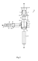
- Figure 1 is a disassembled view of a hemostasis mechanism, with certain components sectioned, according to one embodiment
- Figure 2 is a sectioned view taken along line 2-2 of Figure 1 ;
- Figure 3 is a sectioned view taken along line 3-3 of Figure 2 ;
- Figure 4 is another sectioned view similar to Figure 3 ;
- Figure 5 is a sectioned side diagrammatic view of the hemostasis mechanism of Figure 1 , in an assembled state
- Figure 6 is a partially sectioned side diagrammatic view of the hemostasis mechanism of Figure 1 at one stage of a treatment procedure, according to one embodiment.
- Mechanism 10 for use in treating a patient, according to one embodiment.
- Mechanism 10 includes a housing 12 defining a through-bore 14 having a longitudinal axis 23, and a port 11 in fluid communication with through-bore 14.
- Housing 12 may include a multi-piece housing in certain embodiments, and having an outer housing piece 21 and a core piece 16.
- Housing 12 may also include a cap 18 attached to outer piece 21 and configured to clamp core piece 16 and a pressure responsive seal 22 within outer piece 21.
- pressure responsive seal 22 extends circumferentially about longitudinal axis 23 within through-bore 14, and includes an outer seal surface 24 exposed to a fluid pressure of port 11, and an inner seal surface 26.
- Housing 12 may also include a tube piece 20 configured to attach to outer housing piece 21 such that through-bore 14 may be placed in fluid communication with a body lumen in a patient, as further described herein.
- a tube piece 20 configured to attach to outer housing piece 21 such that through-bore 14 may be placed in fluid communication with a body lumen in a patient, as further described herein.
- the present disclosure sets forth unique design and methodology for controlling sealing engagement of pressure responsive seal 22 about a transluminal device positioned within through-bore 14 and extending through mechanism 10 into a body lumen of a patient such as a vein or artery.
- Mechanism 10 also includes a pressurization device 30 in fluid communication with port 11, and including a plunger 34 movable from a first position approximately as shown in Figure 1 , toward an advanced position, to increase a fluid pressure of port 11 such that seal 22 deforms into sealing engagement with a transluminal device.
- Device 30 further includes a detent 36 operably coupled with plunger 34 and having a release state, and an engaged state holding plunger 34 at an advanced position to maintain the increased fluid pressure.
- core piece 16 will be positioned within outer housing piece 21, and port 17 will be placed in fluid communication with port 11 such that ports 11 and 17 together communicate a fluid pressure of pressurization device 30 to seal 22.
- housing pieces 21 and 16 could be formed as a single piece having a single port.
- Core piece 16 includes an inner housing surface 19 defining through-bore 14. Where no core piece is used, the single housing piece taking the place of outer housing piece 21 and core piece 16 could be understood to include the inner housing surface defining the through-bore.
- Seal 22 may be formed of a suitable deformable material such as a rubber-like material or silicone, and may have a cylindrical wall 38 which includes inner seal surface 26 and outer seal surface 24, cylindrical wall 38 having a longitudinal passage 40 formed therein for receipt of a transluminal device and being co-axial with through-bore 14 when mechanism 10 is assembled for receipt of a transluminal device. Seal 22 may further include a first end flange 42 and a second end flange 44, each projecting radially outward from cylindrical wall 38. When mechanism 10 is assembled, core piece 16 may be positioned about cylindrical wall 38 between first and second end flanges 42 and 44.
- Outer piece 21 may contain seal 22 and core piece 16 therein, and cap 18 may be attached to outer piece 21 and clamps core piece 16 and seal 22 within outer piece 21.
- Cap 18 might be attached to outer piece 21 via an adhesive, threads, or an interference fit or the like, such that first end flange 42 is compressed and held in sealing engagement between cap 18 and core piece 16, and second end flange 44 is compressed and held in sealing engagement between outer piece 21 and core piece 16, the significance of which will be further apparent from the following description and illustrated by way of subsequently described drawings.
- sealing protrusions 46 are crescent shaped, and a total of three such sealing protrusions 46 are provided.
- protrusions 46 form a tricuspid sealing pattern about the transluminal device extending through passage 40 and through-bore 14.
- Figure 4 illustrates an example tricuspid sealing pattern.
- mechanism 10 assembled, where cap 18 is attached to outer piece 21 and clamps core piece 16 and seal 22 therein.
- Tube 20 is attached to outer housing piece 21, and pressurization device 30 is also attached to outer piece 21 such that a cavity 70 formed in a housing 32 of pressurization device 30 is in fluid communication with port 11, port 17, and a clearance 48 which extends between inner housing surface 19 and outer seal surface 24 and surrounds seal 22.
- Fluid communication between clearance 48 and cavity 70 via ports 11 and 17 allows a pressure of a fluid, such as air, or saline, to act upon seal 22 to deform the same, thereby controlling the sealing engagement between seal 22 and a transluminal device extending through mechanism 10.
- a fluid such as air, or saline
- pressurization device 30 further includes a biasing spring 52 positioned within cavity 70 and biasing plunger 34 toward the first position, approximately as shown in Figure 5 .
- Pressurization device 30 may further include a plunger actuator 54 coupled with plunger 34, and which could be formed as one piece therewith, configured to control advancing and retracting of plunger 34 to vary fluid pressure in cavity 70 and thereby control the sealing engagement of seal 22.
- Actuator 54 may include a button or the like configured to be pushed by a clinician to advance and retract plunger 34, and also to adjust detent 36 between its engaged state and its release state as further described herein.
- plunger 34 may be retracted, such as under the influence of spring 52, and also under the influence of a fluid pressure in cavity 70.
- plunger 34 In the engaged state of detent 36, plunger 34 will be held at its advanced position to maintain an increased pressure in cavity 70, and thereby maintain sealing engagement of seal 22 about the transluminal device.
- pushing actuator 54 may push plunger 34 to advance the same, and simultaneously adjust detent 36 to its release state or its engaged state, as the case may be.
- a biasing spring 56 may be positioned between actuator 54 and housing 32 to bias actuator 54 away from and out of contact with plunger 34. Any suitable retention mechanism might be employed to prevent actuator 54 from popping out of housing 32 if desired.
- detent 36 may function in a manner analogous to that of detents used in connection with certain ball point pens.
- plunger 34 may define a transverse axis 25, and detent 36 may further include a non-rotatable stop 58, formed integrally with housing 32 for example, and a rotatable catch 60 coupled with plunger 34.
- Catch 60 may be movable between a first angular orientation about transverse axis 25 at which catch 60 contacts stop 58 and retracting of plunger 34 from its advanced position is prevented, and a second orientation at which retracting of plunger 34 is permitted.
- detent 36 is shown in its release state such that catch 60 is not engaged with stop 58 and plunger 34 has moved to a first, retracted position via spring 52.
- a plurality of ribs 62 of catch 60 have been permitted to slide past a plurality of counterpart ribs 63 of stop 58.
- Catch 60 is thus at an example second orientation about axis 25.
- Ribs 62 may each include an angled end surface 64 which is engaged by counterpart angled end surfaces 66 on the end of actuator 54. Sliding engagement between end surfaces 66 and 64 as actuator 54 is advanced, in opposition to a force of spring 56, can impart a tendency for catch 60 to rotate about axis 25 to a position at which ribs 62 contact ribs 63.
- catch 62 is coupled with plunger 34, and may be attached to plunger 34, when ribs 62 are rotated to a position at which they engage ribs 63, plunger 34 is held in an advanced position.
- facing end surfaces of the respective ribs may contact one another to inhibit axial sliding of catch 60 and plunger 34 to the left in Figure 5 .
- mechanism 10 as it might appear with a transluminal device 80 extending therethrough, and into a patient via an introducer 82 providing an entry point 90 into a body lumen 100 of the patient.
- plunger 34 has been pushed toward an advanced positioned in pressurization device 30 by pushing actuator 54.
- Actuator 54 has interacted with catch 60 to rotate catch 60 to its first angular orientation at which it contacts stop 54 such that retracting of plunger 34 from its advanced position is prevented.
- detent 36 has thus been adjusted to its engaged state inhibiting retracting of plunger 34.
- Fluid pressure in cavity 70 has thus increased to supply an increased fluid pressure to clearance 48.
- Seal 22, and in particular cylindrical wall 38 has deformed in response to the increased pressure such that sealing protrusions 46 contact transluminal device 80.
- transluminal device 80 which may include a catheter, wire guide, or some other mechanism, in this general manner may be performed for various purposes such as the injection of fluid into the body lumen, to prevent backflow of the fluid during injecting, or simply to prevent blood from the body lumen from flowing back through the apparatus providing percutaneous access.
- a side arm fitting or the like might be coupled with mechanism 10 or introducer 82 to enable a second fluid access path into body lumen 100.
- actuator 54 may be pushed again to adjust detent 36 from its engaged state inhibiting retracting of plunger 34, to its release state.
- plunger 34 may be slightly advanced within housing 32 when actuator 54 is pushed to release detent 36.
- plunger 34 may retract such that fluid pressure supplied by device 30 to seal 22 is reduced.
- the fluid pressure in cavity 70, and an expanding force of spring 52 may urge plunger 34 back toward its retracted position with detent 36 released.
- the reduced pressure in clearance 48 will reduce the sealing force of seal 22 about transluminal device 80. This facilitates sliding oftransluminal device 80 to a changed position within body lumen 100, while the pressure in clearance 48 is at a reduced pressure such as the position shown via phantom lines in Figure 6 .
- a clinician may reestablish sealing engagement of seal 22 about device 80 at a changed position, and adjust detent 36 back to its engaged state to maintain the reestablished sealing engagement, in response to another pushing of actuator 54 and thus plunger 34 toward an advanced position.
- known hemostasis mechanism suffer from a variety of drawbacks.
- one drawback is commonly the need to manually maintain a pressure about a hemostasis seal.
- a clinician may let go of plunger 34, in particular letting go of actuator 54, subsequent to adjusting detent 36 to, or back to, its engaged state.
- Another shortcoming associated with certain known hemostasis mechanisms is the lack of any positive feedback to a clinician indicating that a seal has been established about a transluminal device. In other words, a clinician will often have no way to know whether the seal formed about a transluminal device is sufficient, but instead relies upon guesswork or experience to determine whether they have supplied sufficient pressure to hold the seal.
- the relatively simple push-button operation of pressurization device 30 allows both hands-free work while the seal is established, and also tactile feedback to the clinician that indicates positive sealing engagement.
- the clinician will typically be able to feel the click when detent 36 is adjusted to its engaged state, and also feel a click when detent 36 is adjusted to its release state.
- Still another feature contemplated to be superior to known designs relates to the capability of pulling open seal 22 via reduced pressure resulting from retracting plunger 34. In other words, a relatively rapid decrease in pressure within clearance 48 can impart a tendency for seal 22 to pop open relatively rapidly, hastening certain aspects of the associated treatment procedure.
- fluid displaced by plunger 34 to control seal 22 will typically be air, for instance a displacement of about 2 milliliters of air, the present disclosure is not thereby limited and as alluded to above saline or some other actuation fluid might instead be used. It should also be appreciated that while pressurization device 30 is shown attached to housing 12, in other instances a separate pressurization device connected via a flexible conduit or the like might be used.
Landscapes
- Health & Medical Sciences (AREA)
- Heart & Thoracic Surgery (AREA)
- Life Sciences & Earth Sciences (AREA)
- Public Health (AREA)
- Engineering & Computer Science (AREA)
- Anesthesiology (AREA)
- Biomedical Technology (AREA)
- Hematology (AREA)
- Animal Behavior & Ethology (AREA)
- General Health & Medical Sciences (AREA)
- Veterinary Medicine (AREA)
- Pulmonology (AREA)
- Vascular Medicine (AREA)
- Biophysics (AREA)
- Child & Adolescent Psychology (AREA)
- Infusion, Injection, And Reservoir Apparatuses (AREA)
Applications Claiming Priority (1)
| Application Number | Priority Date | Filing Date | Title |
|---|---|---|---|
| US201261613120P | 2012-03-20 | 2012-03-20 |
Publications (2)
| Publication Number | Publication Date |
|---|---|
| EP2641632A1 true EP2641632A1 (de) | 2013-09-25 |
| EP2641632B1 EP2641632B1 (de) | 2020-05-06 |
Family
ID=47998207
Family Applications (1)
| Application Number | Title | Priority Date | Filing Date |
|---|---|---|---|
| EP13160238.5A Active EP2641632B1 (de) | 2012-03-20 | 2013-03-20 | Hämostasemechanismus |
Country Status (2)
| Country | Link |
|---|---|
| US (1) | US9216277B2 (de) |
| EP (1) | EP2641632B1 (de) |
Families Citing this family (23)
| Publication number | Priority date | Publication date | Assignee | Title |
|---|---|---|---|---|
| US7686825B2 (en) | 2004-03-25 | 2010-03-30 | Hauser David L | Vascular filter device |
| US8784434B2 (en) | 2012-11-20 | 2014-07-22 | Inceptus Medical, Inc. | Methods and apparatus for treating embolism |
| US10238406B2 (en) | 2013-10-21 | 2019-03-26 | Inari Medical, Inc. | Methods and apparatus for treating embolism |
| AU2016341439B2 (en) | 2015-10-23 | 2021-07-08 | Stryker Corporation | Intravascular treatment of vascular occlusion and associated devices, systems, and methods |
| JP7012655B2 (ja) | 2016-02-24 | 2022-01-28 | インセプト、リミテッド、ライアビリティ、カンパニー | 可撓性の強化された神経血管カテーテル |
| CN116421266A (zh) | 2016-10-24 | 2023-07-14 | 伊纳里医疗有限公司 | 用于治疗血管闭塞的装置和方法 |
| EP3600523A4 (de) * | 2017-05-09 | 2020-09-16 | Merit Medical Systems, Inc. | Hämostasedrehmomentanordnung |
| DK3678731T3 (da) | 2017-09-06 | 2025-01-02 | Inari Medical Inc | Hemostasis valves and methods of use |
| US11154314B2 (en) | 2018-01-26 | 2021-10-26 | Inari Medical, Inc. | Single insertion delivery system for treating embolism and associated systems and methods |
| US11559382B2 (en) | 2018-08-13 | 2023-01-24 | Inari Medical, Inc. | System for treating embolism and associated devices and methods |
| WO2020140072A1 (en) * | 2018-12-28 | 2020-07-02 | Auris Health, Inc. | Percutaneous sheath for robotic medical systems and methods |
| US11672661B2 (en) | 2019-08-22 | 2023-06-13 | Silara Medtech Inc. | Annuloplasty systems and methods |
| CA3157521A1 (en) | 2019-10-16 | 2021-04-22 | Inari Medical, Inc. | Systems, devices, and methods for treating vascular occlusions |
| US11439799B2 (en) | 2019-12-18 | 2022-09-13 | Imperative Care, Inc. | Split dilator aspiration system |
| WO2021136460A1 (zh) * | 2019-12-31 | 2021-07-08 | 杭州启明医疗器械股份有限公司 | 止血阀、导管鞘以及介入器械的密封方法 |
| EP4663214A3 (de) | 2020-06-05 | 2026-02-25 | Inari Medical, Inc. | Rückholbare trichterkatheter und zugehörige systeme |
| EP4281168A4 (de) * | 2021-01-19 | 2024-12-25 | Silara Medtech Inc. | Hämostaseventil, einführvorrichtung und rückholvorrichtung |
| JP2024541260A (ja) * | 2021-10-29 | 2024-11-08 | ベクトン・ディキンソン・アンド・カンパニー | 触覚フィードバック機構を有する採血装置 |
| US12364496B2 (en) | 2022-01-11 | 2025-07-22 | Inari Medical, Inc. | Devices for removing clot material from intravascularly implanted devices, and associated systems and methods |
| JP2026501789A (ja) | 2023-01-09 | 2026-01-16 | イナリ メディカル, インコーポレイテッド | 凝塊治療システムと共に使用するためのカテーテル |
| AU2024380408A1 (en) | 2023-11-16 | 2026-05-07 | Inari Medical, Inc. | Automatic locking and unlocking vacuum syringes, and associated systems and methods |
| US12465382B1 (en) | 2024-05-10 | 2025-11-11 | Inari Medical, Inc. | Mechanical thrombectomy assemblies with relief features, and associated devices, systems, and methods |
| WO2026089864A1 (en) * | 2024-10-24 | 2026-04-30 | St. Jude Medical, Cardiology Division, Inc. | Hemostasis valve for vascular device |
Citations (8)
| Publication number | Priority date | Publication date | Assignee | Title |
|---|---|---|---|---|
| EP0307743A1 (de) * | 1987-09-17 | 1989-03-22 | Joka Kathetertechnik Gmbh | Absperrvorrichtung an einer Flüssigkeitsentnahme- oder Infusionseinrichtung |
| US5871474A (en) * | 1995-05-19 | 1999-02-16 | General Surgical Innovations, Inc. | Screw-type skin seal with inflatable membrane |
| WO1999011308A1 (en) * | 1997-09-02 | 1999-03-11 | Delcath Systems, Inc. | Catheter flow and lateral movement controller |
| EP1046843A2 (de) * | 1999-04-19 | 2000-10-25 | Ferton Holding SA | Quetschventil |
| US6276661B1 (en) * | 1996-11-06 | 2001-08-21 | Medtronic, Inc. | Pressure actuated introducer valve |
| US20040172008A1 (en) | 2002-11-19 | 2004-09-02 | Gmp/Cardiac Care, Inc. | Hemostasis valve and method of using a hemostasis valve |
| US7597688B1 (en) * | 2004-12-27 | 2009-10-06 | Masson Marcos V | Cannula apparatus with inflatable seal and adjustable length |
| US20110282301A1 (en) * | 2010-05-11 | 2011-11-17 | Cook Medical Technologies Llc | Haemostatic valve assembly |
Family Cites Families (4)
| Publication number | Priority date | Publication date | Assignee | Title |
|---|---|---|---|---|
| US5127906A (en) * | 1989-04-28 | 1992-07-07 | Flp Enterprises, Inc. | Non-reusable syringe |
| US5338313A (en) | 1992-12-17 | 1994-08-16 | Thomas J. Fogarty, M.D. | Adjustable valve having a radially compressible sealing body |
| US5895376A (en) | 1996-10-23 | 1999-04-20 | Mayo Foundation For Medical Education And Research | Hemostasis valve, system and assembly |
| US6425885B1 (en) * | 1999-12-20 | 2002-07-30 | Ultradent Products, Inc. | Hydraulic syringe |
-
2013
- 2013-02-18 US US13/769,510 patent/US9216277B2/en active Active
- 2013-03-20 EP EP13160238.5A patent/EP2641632B1/de active Active
Patent Citations (8)
| Publication number | Priority date | Publication date | Assignee | Title |
|---|---|---|---|---|
| EP0307743A1 (de) * | 1987-09-17 | 1989-03-22 | Joka Kathetertechnik Gmbh | Absperrvorrichtung an einer Flüssigkeitsentnahme- oder Infusionseinrichtung |
| US5871474A (en) * | 1995-05-19 | 1999-02-16 | General Surgical Innovations, Inc. | Screw-type skin seal with inflatable membrane |
| US6276661B1 (en) * | 1996-11-06 | 2001-08-21 | Medtronic, Inc. | Pressure actuated introducer valve |
| WO1999011308A1 (en) * | 1997-09-02 | 1999-03-11 | Delcath Systems, Inc. | Catheter flow and lateral movement controller |
| EP1046843A2 (de) * | 1999-04-19 | 2000-10-25 | Ferton Holding SA | Quetschventil |
| US20040172008A1 (en) | 2002-11-19 | 2004-09-02 | Gmp/Cardiac Care, Inc. | Hemostasis valve and method of using a hemostasis valve |
| US7597688B1 (en) * | 2004-12-27 | 2009-10-06 | Masson Marcos V | Cannula apparatus with inflatable seal and adjustable length |
| US20110282301A1 (en) * | 2010-05-11 | 2011-11-17 | Cook Medical Technologies Llc | Haemostatic valve assembly |
Also Published As
| Publication number | Publication date |
|---|---|
| US20130253565A1 (en) | 2013-09-26 |
| EP2641632B1 (de) | 2020-05-06 |
| US9216277B2 (en) | 2015-12-22 |
Similar Documents
| Publication | Publication Date | Title |
|---|---|---|
| US9216277B2 (en) | Hemostasis mechanism and method | |
| US9675792B2 (en) | Hemostasis mechanism and method | |
| US11458285B2 (en) | Locking mechanism for a medical device | |
| US9592372B2 (en) | Linkage actuated hemostasis mechanism and method | |
| USRE49369E1 (en) | Drug delivery device with pneumatic power pack | |
| EP1660173B1 (de) | Hämostasevorrichtung | |
| US10441773B2 (en) | Ported catheter adapter with integrated septum actuator retention | |
| US6834842B2 (en) | Fluid management valve | |
| US10449331B2 (en) | Catheter devices with seals and related methods | |
| US11077295B2 (en) | System for connecting a blood pump to a heart | |
| CN105228689A (zh) | 多用途的静脉导管组件隔膜和隔膜致动器 | |
| CN104039384A (zh) | 多次使用的拉伸和非穿透血液控制阀 | |
| CA2598951A1 (en) | Medical apparatus and method of use thereof | |
| US8216186B2 (en) | Catheter device with hooding feature | |
| AU2014202455A1 (en) | Lockable syringe and method of assembling same | |
| CN106163433A (zh) | 抗逆流导管 | |
| EP3866887A1 (de) | Flüssigkeitstransfervorrichtungen | |
| CN119343160A (zh) | 用于输送药剂的装置、组件和方法 |
Legal Events
| Date | Code | Title | Description |
|---|---|---|---|
| PUAI | Public reference made under article 153(3) epc to a published international application that has entered the european phase |
Free format text: ORIGINAL CODE: 0009012 |
|
| AK | Designated contracting states |
Kind code of ref document: A1 Designated state(s): AL AT BE BG CH CY CZ DE DK EE ES FI FR GB GR HR HU IE IS IT LI LT LU LV MC MK MT NL NO PL PT RO RS SE SI SK SM TR |
|
| AX | Request for extension of the european patent |
Extension state: BA ME |
|
| 17P | Request for examination filed |
Effective date: 20140325 |
|
| RBV | Designated contracting states (corrected) |
Designated state(s): AL AT BE BG CH CY CZ DE DK EE ES FI FR GB GR HR HU IE IS IT LI LT LU LV MC MK MT NL NO PL PT RO RS SE SI SK SM TR |
|
| STAA | Information on the status of an ep patent application or granted ep patent |
Free format text: STATUS: EXAMINATION IS IN PROGRESS |
|
| 17Q | First examination report despatched |
Effective date: 20190627 |
|
| GRAP | Despatch of communication of intention to grant a patent |
Free format text: ORIGINAL CODE: EPIDOSNIGR1 |
|
| STAA | Information on the status of an ep patent application or granted ep patent |
Free format text: STATUS: GRANT OF PATENT IS INTENDED |
|
| INTG | Intention to grant announced |
Effective date: 20191129 |
|
| GRAS | Grant fee paid |
Free format text: ORIGINAL CODE: EPIDOSNIGR3 |
|
| GRAA | (expected) grant |
Free format text: ORIGINAL CODE: 0009210 |
|
| STAA | Information on the status of an ep patent application or granted ep patent |
Free format text: STATUS: THE PATENT HAS BEEN GRANTED |
|
| AK | Designated contracting states |
Kind code of ref document: B1 Designated state(s): AL AT BE BG CH CY CZ DE DK EE ES FI FR GB GR HR HU IE IS IT LI LT LU LV MC MK MT NL NO PL PT RO RS SE SI SK SM TR |
|
| REG | Reference to a national code |
Ref country code: GB Ref legal event code: FG4D |
|
| REG | Reference to a national code |
Ref country code: AT Ref legal event code: REF Ref document number: 1265806 Country of ref document: AT Kind code of ref document: T Effective date: 20200515 Ref country code: CH Ref legal event code: EP |
|
| REG | Reference to a national code |
Ref country code: DE Ref legal event code: R096 Ref document number: 602013068644 Country of ref document: DE |
|
| REG | Reference to a national code |
Ref country code: IE Ref legal event code: FG4D |
|
| REG | Reference to a national code |
Ref country code: LT Ref legal event code: MG4D |
|
| REG | Reference to a national code |
Ref country code: NL Ref legal event code: MP Effective date: 20200506 |
|
| PG25 | Lapsed in a contracting state [announced via postgrant information from national office to epo] |
Ref country code: PT Free format text: LAPSE BECAUSE OF FAILURE TO SUBMIT A TRANSLATION OF THE DESCRIPTION OR TO PAY THE FEE WITHIN THE PRESCRIBED TIME-LIMIT Effective date: 20200907 Ref country code: SE Free format text: LAPSE BECAUSE OF FAILURE TO SUBMIT A TRANSLATION OF THE DESCRIPTION OR TO PAY THE FEE WITHIN THE PRESCRIBED TIME-LIMIT Effective date: 20200506 Ref country code: IS Free format text: LAPSE BECAUSE OF FAILURE TO SUBMIT A TRANSLATION OF THE DESCRIPTION OR TO PAY THE FEE WITHIN THE PRESCRIBED TIME-LIMIT Effective date: 20200906 Ref country code: FI Free format text: LAPSE BECAUSE OF FAILURE TO SUBMIT A TRANSLATION OF THE DESCRIPTION OR TO PAY THE FEE WITHIN THE PRESCRIBED TIME-LIMIT Effective date: 20200506 Ref country code: LT Free format text: LAPSE BECAUSE OF FAILURE TO SUBMIT A TRANSLATION OF THE DESCRIPTION OR TO PAY THE FEE WITHIN THE PRESCRIBED TIME-LIMIT Effective date: 20200506 Ref country code: NO Free format text: LAPSE BECAUSE OF FAILURE TO SUBMIT A TRANSLATION OF THE DESCRIPTION OR TO PAY THE FEE WITHIN THE PRESCRIBED TIME-LIMIT Effective date: 20200806 Ref country code: GR Free format text: LAPSE BECAUSE OF FAILURE TO SUBMIT A TRANSLATION OF THE DESCRIPTION OR TO PAY THE FEE WITHIN THE PRESCRIBED TIME-LIMIT Effective date: 20200807 |
|
| PG25 | Lapsed in a contracting state [announced via postgrant information from national office to epo] |
Ref country code: BG Free format text: LAPSE BECAUSE OF FAILURE TO SUBMIT A TRANSLATION OF THE DESCRIPTION OR TO PAY THE FEE WITHIN THE PRESCRIBED TIME-LIMIT Effective date: 20200806 Ref country code: HR Free format text: LAPSE BECAUSE OF FAILURE TO SUBMIT A TRANSLATION OF THE DESCRIPTION OR TO PAY THE FEE WITHIN THE PRESCRIBED TIME-LIMIT Effective date: 20200506 Ref country code: LV Free format text: LAPSE BECAUSE OF FAILURE TO SUBMIT A TRANSLATION OF THE DESCRIPTION OR TO PAY THE FEE WITHIN THE PRESCRIBED TIME-LIMIT Effective date: 20200506 Ref country code: RS Free format text: LAPSE BECAUSE OF FAILURE TO SUBMIT A TRANSLATION OF THE DESCRIPTION OR TO PAY THE FEE WITHIN THE PRESCRIBED TIME-LIMIT Effective date: 20200506 |
|
| REG | Reference to a national code |
Ref country code: AT Ref legal event code: MK05 Ref document number: 1265806 Country of ref document: AT Kind code of ref document: T Effective date: 20200506 |
|
| PG25 | Lapsed in a contracting state [announced via postgrant information from national office to epo] |
Ref country code: NL Free format text: LAPSE BECAUSE OF FAILURE TO SUBMIT A TRANSLATION OF THE DESCRIPTION OR TO PAY THE FEE WITHIN THE PRESCRIBED TIME-LIMIT Effective date: 20200506 Ref country code: AL Free format text: LAPSE BECAUSE OF FAILURE TO SUBMIT A TRANSLATION OF THE DESCRIPTION OR TO PAY THE FEE WITHIN THE PRESCRIBED TIME-LIMIT Effective date: 20200506 |
|
| PG25 | Lapsed in a contracting state [announced via postgrant information from national office to epo] |
Ref country code: EE Free format text: LAPSE BECAUSE OF FAILURE TO SUBMIT A TRANSLATION OF THE DESCRIPTION OR TO PAY THE FEE WITHIN THE PRESCRIBED TIME-LIMIT Effective date: 20200506 Ref country code: RO Free format text: LAPSE BECAUSE OF FAILURE TO SUBMIT A TRANSLATION OF THE DESCRIPTION OR TO PAY THE FEE WITHIN THE PRESCRIBED TIME-LIMIT Effective date: 20200506 Ref country code: IT Free format text: LAPSE BECAUSE OF FAILURE TO SUBMIT A TRANSLATION OF THE DESCRIPTION OR TO PAY THE FEE WITHIN THE PRESCRIBED TIME-LIMIT Effective date: 20200506 Ref country code: CZ Free format text: LAPSE BECAUSE OF FAILURE TO SUBMIT A TRANSLATION OF THE DESCRIPTION OR TO PAY THE FEE WITHIN THE PRESCRIBED TIME-LIMIT Effective date: 20200506 Ref country code: AT Free format text: LAPSE BECAUSE OF FAILURE TO SUBMIT A TRANSLATION OF THE DESCRIPTION OR TO PAY THE FEE WITHIN THE PRESCRIBED TIME-LIMIT Effective date: 20200506 Ref country code: DK Free format text: LAPSE BECAUSE OF FAILURE TO SUBMIT A TRANSLATION OF THE DESCRIPTION OR TO PAY THE FEE WITHIN THE PRESCRIBED TIME-LIMIT Effective date: 20200506 Ref country code: SM Free format text: LAPSE BECAUSE OF FAILURE TO SUBMIT A TRANSLATION OF THE DESCRIPTION OR TO PAY THE FEE WITHIN THE PRESCRIBED TIME-LIMIT Effective date: 20200506 Ref country code: ES Free format text: LAPSE BECAUSE OF FAILURE TO SUBMIT A TRANSLATION OF THE DESCRIPTION OR TO PAY THE FEE WITHIN THE PRESCRIBED TIME-LIMIT Effective date: 20200506 |
|
| REG | Reference to a national code |
Ref country code: DE Ref legal event code: R097 Ref document number: 602013068644 Country of ref document: DE |
|
| PG25 | Lapsed in a contracting state [announced via postgrant information from national office to epo] |
Ref country code: SK Free format text: LAPSE BECAUSE OF FAILURE TO SUBMIT A TRANSLATION OF THE DESCRIPTION OR TO PAY THE FEE WITHIN THE PRESCRIBED TIME-LIMIT Effective date: 20200506 Ref country code: PL Free format text: LAPSE BECAUSE OF FAILURE TO SUBMIT A TRANSLATION OF THE DESCRIPTION OR TO PAY THE FEE WITHIN THE PRESCRIBED TIME-LIMIT Effective date: 20200506 |
|
| PLBE | No opposition filed within time limit |
Free format text: ORIGINAL CODE: 0009261 |
|
| STAA | Information on the status of an ep patent application or granted ep patent |
Free format text: STATUS: NO OPPOSITION FILED WITHIN TIME LIMIT |
|
| 26N | No opposition filed |
Effective date: 20210209 |
|
| PG25 | Lapsed in a contracting state [announced via postgrant information from national office to epo] |
Ref country code: SI Free format text: LAPSE BECAUSE OF FAILURE TO SUBMIT A TRANSLATION OF THE DESCRIPTION OR TO PAY THE FEE WITHIN THE PRESCRIBED TIME-LIMIT Effective date: 20200506 |
|
| PG25 | Lapsed in a contracting state [announced via postgrant information from national office to epo] |
Ref country code: MC Free format text: LAPSE BECAUSE OF FAILURE TO SUBMIT A TRANSLATION OF THE DESCRIPTION OR TO PAY THE FEE WITHIN THE PRESCRIBED TIME-LIMIT Effective date: 20200506 |
|
| REG | Reference to a national code |
Ref country code: CH Ref legal event code: PL |
|
| REG | Reference to a national code |
Ref country code: BE Ref legal event code: MM Effective date: 20210331 |
|
| PG25 | Lapsed in a contracting state [announced via postgrant information from national office to epo] |
Ref country code: CH Free format text: LAPSE BECAUSE OF NON-PAYMENT OF DUE FEES Effective date: 20210331 Ref country code: LU Free format text: LAPSE BECAUSE OF NON-PAYMENT OF DUE FEES Effective date: 20210320 Ref country code: LI Free format text: LAPSE BECAUSE OF NON-PAYMENT OF DUE FEES Effective date: 20210331 Ref country code: FR Free format text: LAPSE BECAUSE OF NON-PAYMENT OF DUE FEES Effective date: 20210331 |
|
| PG25 | Lapsed in a contracting state [announced via postgrant information from national office to epo] |
Ref country code: BE Free format text: LAPSE BECAUSE OF NON-PAYMENT OF DUE FEES Effective date: 20210331 |
|
| PG25 | Lapsed in a contracting state [announced via postgrant information from national office to epo] |
Ref country code: HU Free format text: LAPSE BECAUSE OF FAILURE TO SUBMIT A TRANSLATION OF THE DESCRIPTION OR TO PAY THE FEE WITHIN THE PRESCRIBED TIME-LIMIT; INVALID AB INITIO Effective date: 20130320 |
|
| PG25 | Lapsed in a contracting state [announced via postgrant information from national office to epo] |
Ref country code: CY Free format text: LAPSE BECAUSE OF FAILURE TO SUBMIT A TRANSLATION OF THE DESCRIPTION OR TO PAY THE FEE WITHIN THE PRESCRIBED TIME-LIMIT Effective date: 20200506 |
|
| P01 | Opt-out of the competence of the unified patent court (upc) registered |
Effective date: 20230602 |
|
| PG25 | Lapsed in a contracting state [announced via postgrant information from national office to epo] |
Ref country code: MK Free format text: LAPSE BECAUSE OF FAILURE TO SUBMIT A TRANSLATION OF THE DESCRIPTION OR TO PAY THE FEE WITHIN THE PRESCRIBED TIME-LIMIT Effective date: 20200506 |
|
| PG25 | Lapsed in a contracting state [announced via postgrant information from national office to epo] |
Ref country code: MT Free format text: LAPSE BECAUSE OF FAILURE TO SUBMIT A TRANSLATION OF THE DESCRIPTION OR TO PAY THE FEE WITHIN THE PRESCRIBED TIME-LIMIT Effective date: 20200506 |
|
| PG25 | Lapsed in a contracting state [announced via postgrant information from national office to epo] |
Ref country code: TR Free format text: LAPSE BECAUSE OF FAILURE TO SUBMIT A TRANSLATION OF THE DESCRIPTION OR TO PAY THE FEE WITHIN THE PRESCRIBED TIME-LIMIT Effective date: 20200506 |
|
| PGFP | Annual fee paid to national office [announced via postgrant information from national office to epo] |
Ref country code: GB Payment date: 20260319 Year of fee payment: 14 |
|
| PGFP | Annual fee paid to national office [announced via postgrant information from national office to epo] |
Ref country code: DE Payment date: 20260320 Year of fee payment: 14 Ref country code: IE Payment date: 20260318 Year of fee payment: 14 |