EP2641671B1 - Hydraulikwerkzeugvorrichtung - Google Patents
Hydraulikwerkzeugvorrichtung Download PDFInfo
- Publication number
- EP2641671B1 EP2641671B1 EP13160123.9A EP13160123A EP2641671B1 EP 2641671 B1 EP2641671 B1 EP 2641671B1 EP 13160123 A EP13160123 A EP 13160123A EP 2641671 B1 EP2641671 B1 EP 2641671B1
- Authority
- EP
- European Patent Office
- Prior art keywords
- connection
- hydraulic
- unit
- hydraulic tool
- tool
- Prior art date
- Legal status (The legal status is an assumption and is not a legal conclusion. Google has not performed a legal analysis and makes no representation as to the accuracy of the status listed.)
- Active
Links
Images

Classifications
-
- B—PERFORMING OPERATIONS; TRANSPORTING
- B21—MECHANICAL METAL-WORKING WITHOUT ESSENTIALLY REMOVING MATERIAL; PUNCHING METAL
- B21J—FORGING; HAMMERING; PRESSING METAL; RIVETING; FORGE FURNACES
- B21J15/00—Riveting
- B21J15/02—Riveting procedures
- B21J15/04—Riveting hollow rivets mechanically
- B21J15/043—Riveting hollow rivets mechanically by pulling a mandrel
-
- B—PERFORMING OPERATIONS; TRANSPORTING
- B21—MECHANICAL METAL-WORKING WITHOUT ESSENTIALLY REMOVING MATERIAL; PUNCHING METAL
- B21J—FORGING; HAMMERING; PRESSING METAL; RIVETING; FORGE FURNACES
- B21J15/00—Riveting
- B21J15/10—Riveting machines
- B21J15/105—Portable riveters
-
- B—PERFORMING OPERATIONS; TRANSPORTING
- B21—MECHANICAL METAL-WORKING WITHOUT ESSENTIALLY REMOVING MATERIAL; PUNCHING METAL
- B21J—FORGING; HAMMERING; PRESSING METAL; RIVETING; FORGE FURNACES
- B21J15/00—Riveting
- B21J15/10—Riveting machines
- B21J15/16—Drives for riveting machines; Transmission means therefor
- B21J15/20—Drives for riveting machines; Transmission means therefor operated by hydraulic or liquid pressure
-
- B—PERFORMING OPERATIONS; TRANSPORTING
- B25—HAND TOOLS; PORTABLE POWER-DRIVEN TOOLS; MANIPULATORS
- B25F—COMBINATION OR MULTI-PURPOSE TOOLS NOT OTHERWISE PROVIDED FOR; DETAILS OR COMPONENTS OF PORTABLE POWER-DRIVEN TOOLS NOT PARTICULARLY RELATED TO THE OPERATIONS PERFORMED AND NOT OTHERWISE PROVIDED FOR
- B25F5/00—Details or components of portable power-driven tools not particularly related to the operations performed and not otherwise provided for
- B25F5/005—Hydraulic driving means
Definitions
- the invention relates to a hydraulic tool device, in particular blind riveting tool device, with a hydraulic tool having a connection receptacle, a hydraulic supply unit having a connection unit designed for connection to the connection receptacle and an actuating unit designed to control a hydraulic drive.
- Hydraulic tool devices having hydraulic tools operated with hydraulic fluid, for example rivet pliers for pressing rivets, are available in various designs from the prior art, for example from the publications DE 103 16 578 A1 . FR 2 542 226 A1 and EP 2 564 949 A2 known. A field of application of such hydraulic tool devices can be found, inter alia, in the repair of motor vehicles, where they have, for example as a hydraulic tool, a riveting tool for pulling blind rivets.
- Such riveting tools usually have a closed structural unit and are connected to a pneumatic hydraulic pressure intensifier (drive) connected to a compressed air source and can be controlled via an actuating unit arranged on the riveting tool.
- drive pneumatic hydraulic pressure intensifier
- Riveting tools are known, which are spatially decoupled via a supply line from a separate drive.
- such riveting tools additionally have an actuating unit, which is structurally connected thereto, on the riveting tool, from which control lines lead to the activation of the drive.
- the handling of the riveting tool in particular in poorly accessible areas of a structure in turn difficult.
- the known hydraulic tools thus either have a very large size or they are due to the rigid connection of a necessary Steuerschlau Ches for driving the drive unit unwieldy.
- the known Hydraulic tools in tight and hard to reach spaces that occur, for example, in the repair of motor vehicles are not used, so that in these areas again hand tools without drive must be used.
- the invention is therefore based on the object to provide a hydraulic tool device, a hydraulic tool and a hydraulic supply unit, which applies particularly high forces in a particularly small, handy and lightweight size and allows a particularly flexible and mobile use in limited space.
- the hydraulic tool device in particular a blind rivet tool device, has a hydraulic tool with a connection receptacle and a hydraulic supply unit with a connection unit designed for connection to the connection receptacle and an actuation unit designed to control a hydraulic drive, wherein the connection receptacle and the connection unit can be connected to one another in an articulated manner.
- the connection unit and the connection receptacle are also matched to one another such that a pressure-tight connection is ensured.
- a hydraulic tool for example a rivet tool or a riveting tool, without structurally connected actuating unit, that is to say with an actuating unit which is detached from a housing of the hydraulic tool, allows a particularly small design of the hydraulic tool, compared to the known types of hydraulic tools, in which the usually for saved an operating unit provided space can be. Due to the articulated connectability of the hydraulic tool without actuating unit, the hydraulic tool can be used in particular in narrow and poorly accessible areas and moved there to its processing point.
- the articulated connection thus also allows use of the hydraulic tool in narrow and difficult to access working areas.
- the user of the hydraulic tool device is therefore also possible to use the hydraulic tool in work areas inaccessible to known hydraulic tools.
- a hydraulic supply unit is understood to mean, in particular, a line carrying the hydraulic fluid, for example a flexible hose or a tube, which are provided with a connection unit for connection to the connection receptacle of the hydraulic tool.
- the actuating unit is a control unit for controlling the drive, which can basically be configured in any desired form.
- the actuating unit may, for example, have a release lever, via which the user can control the supply of, for example, compressed air to the drive, whereby ultimately the hydraulic tool is activated.
- connection receptacle and terminal unit are also basically freely selectable.
- connection receptacle and the connection unit are designed such that they are rotatable and / or pivotable in the connected state relative to each other.
- Such an embodiment of the invention can be particularly simple and inexpensive and reliable and offers the user a high flexibility in handling.
- a rotatability is understood to mean a possibility of movement about a common longitudinal axis of the connection receptacle and the connection unit.
- both the connection receptacle and the connection unit can be designed to be rotatable, for example rotatable relative to one another.
- a configuration is possible in which a complete rotatability, ie a 360 ° rotational movement of the connection receptacle and / or the connection unit, can be done. That is, the hydraulic tool can perform at least one complete (360 °) rotational movement about a common longitudinal axis due to its articulated connection relative to the hydraulic supply unit.
- a pivotability is understood as meaning a movement about a transverse axis of the connection receptacle and / or the connection unit, wherein in this context a transverse axis is an axis extending transversely to the longitudinal axis.
- the transverse axis is aligned at an angle of 90 ° +/- 10 ° to the longitudinal axis.
- the respective longitudinal axes of the connection receptacle and the connection unit thus run in the pivoted state at an angle to one another.
- connection receptacle and the connection unit can be pivoted by up to 30 °, preferably 60 °, particularly preferably 90 °, preferably 120 °, advantageously 150 ° and particularly advantageously 180 ° to one another. That the hydraulic tool can be pivoted up to +/- 90 ° from an initial position in which the connection receptacle and the connection unit have a common longitudinal axis.
- a pivotability in the preferred angle range improves the possibilities of using the hydraulic tool device in particularly narrow, narrow and difficult to access areas.
- connection unit is connected to the actuating unit according to an embodiment of the invention, wherein the actuating unit is designed for pivotally and / or pivotally connected to the connection receptacle.
- the actuating unit can thus be connected directly rotatably or pivotally with the arranged on the hydraulic tool connection receptacle.
- the hydraulic supply unit is connected to the actuating unit in this particular embodiment, so that the hydraulic fluid provided by the hydraulic supply unit is preferably guided through the actuating unit to the hydraulic tool.
- the actuation unit can thus be coupled to the connection unit and the connection receptacle educated.
- the user can activate or deactivate the hydraulic tool as usual, but in addition to the hydraulic tool has the necessary freedom of movement to use this in particularly narrow and difficult to access work areas.
- the hydraulic supply unit can be rotatably and / or pivotally connected to the connection unit.
- the hydraulic supply unit can be pivoted and / or rotated relative to the operating unit according to this women training the invention, so that their position can be particularly easily adapted to the necessary operating position of the hydraulic tool.
- the rotatable and / or pivotable design between the actuating unit and the connection unit or between the connection receptacle and the actuating unit is particularly advantageously designed in accordance with the rotatable and / or pivotable configuration between the connection receptacle and the connection unit, whereby a higher overall variability is achieved.
- FIG. 1 a In a schematic cross section shows the FIG. 1 a trained as a blind riveting tool hydraulic tool 1.
- the hydraulic tool 1 has a connection receptacle 2 with a rotatably connected actuator unit 3.
- the connection receptacle 2 is designed for a rotatable connection.
- the connection receptacle 2 and the plug unit 4 have a common longitudinal axis 5.
- the hydraulic tool 1 with the connection piece 2 arranged on the hydraulic tool 1 is thus rotatable relative to the actuating unit 3 about the longitudinal axis 5. That is, the hydraulic tool 1 is free - at least 360 ° - rotatable about the longitudinal axis 5.
- FIG. 1 a shows one of the plug unit 4 opposite side of the actuator unit 3 further, a rotatable connection enabling terminal receptacle 6 on.
- a hydraulic supply unit 7 is coupled to the further connection receptacle 6.
- a connection unit 8 is arranged on the hydraulic supply unit 7, which is connected to the further connection receptacle 6.
- the hydraulic tool 1 may, for example, also be connected rotatably directly to the hydraulic supply unit 7, wherein the actuating unit 3 in this case with the hydraulic supply unit 7 or alternatively directly with a pneumatic hydraulic pressure intensifier (Drive) (not shown here) is connected.
- a pneumatic hydraulic pressure intensifier Drive
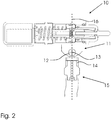
- FIG. 2 shows a further embodiment of a hydraulic tool 10 with a trained for pivotable assembly terminal receiving 11.
- the terminal receptacle 11 is integrally formed with the hydraulic tool 10.
- the connection receptacle 11 is connected to a connection unit 12 designed for pivotable arrangement.
- the connection receptacle 11 and the connection unit 12 have a common transverse axis 13 (pivot axis) (shown here as a cross), about which the hydraulic tool 10 can be pivoted by up to +/- 90 °.
- connection unit 12 further has, on a side opposite the hydraulic tool 10, a connection receptacle 14 with a rotatably connected hydraulic supply unit 15.
- the hydraulic supply unit 15 and the terminal receptacle 14 are in accordance with the in FIG. 1 illustrated terminal receptacle 2, 6 and terminal unit 8 and the plug unit 4 is formed.
- the hydraulic tool 10 is thus rotatable relative to the hydraulic supply unit 15 about a longitudinal axis 16 (shown here as a dashed line) and pivotable about the transverse axis 13.
- the hydraulic supply unit 15 and / or the actuating unit 3 can also be fixedly, detachably and / or immovably connected to the connection receptacle 14.
Landscapes
- Engineering & Computer Science (AREA)
- Mechanical Engineering (AREA)
- Fluid-Pressure Circuits (AREA)
- Portable Nailing Machines And Staplers (AREA)
Description
- Die Erfindung betrifft eine Hydraulikwerkzeugvorrichtung, insbesondere Blindnietwerkzeugvorrichtung, mit einem eine Anschlussaufnahme aufweisenden Hydraulikwerkzeug, einer Hydraulikversorgungseinheit mit einer zur Verbindung mit der Anschlussaufnahme ausgebildeten Anschlusseinheit und einer zur Steuerung eines Hydraulikantriebs ausgebildeten Betätigungseinheit.
- Hydraulikwerkzeugvorrichtungen, die mit Hydraulikflüssigkeit betriebene Hydraulikwerkzeuge, bspw. Nietzangen zum Verpressen von Nieten aufweisen, sind in vielfältigen Ausgestaltungen aus dem Stand der Technik, beispielsweise aus den Druckschriften
DE 103 16 578 A1 ,FR 2 542 226 A1 EP 2 564 949 A2 bekannt. Ein Einsatzbereich derartiger Hydraulikwerkzeugvorrichtungen findet sich u. a. bei der Reparatur von Kraftfahrzeugen, wo diese beispielsweise als Hydraulikwerkzeug ein Nietwerkzeug zum Ziehen von Blindnieten aufweisen. Derartige Nietwerkzeuge weisen üblicherweise eine geschlossene Baueinheit auf und sind mit einem an eine Druckluftquelle angeschlossenen Pneumatik-Hydraulik-Druckübersetzer (Antrieb) verbunden und können über eine am Nietwerkzeug angeordnete Betätigungseinheit gesteuert werden. - Um die Handhabbarkeit derartiger Hydraulikwerkzeuge zu verbessern, sind bspw. Nietwerkzeuge bekannt, die über eine Versorgungsleitung von einem separaten Antrieb räumlich entkoppelt sind. Derartige Nietwerkzeuge weisen jedoch in der Regel zusätzlich eine baulich mit dieser verbundene Betätigungseinheit am Nietwerkzeug auf, von der aus Steuerungsleitungen zum Ansteuern des Antriebs führen. Hierdurch wird jedoch die Handhabung des Nietwerkzeugs, insbesondere in schlecht zugänglichen Bereichen eines Baukörpers wiederum erschwert.
- Die bekannten Hydraulikwerkzeuge weisen somit entweder eine ausgesprochen große Baugröße auf oder sie sind aufgrund der starren Anbindung eines notwendigen Steuerschlau ches zum Ansteuern der Antriebseinheit unhandlich. In jedem Fall können die bekannten Hydraulikwerkzeuge in engen und schwer zugänglichen Zwischenräumen, die beispielsweise bei der Reparatur von Kraftfahrzeugen auftreten, nicht eingesetzt werden, so dass in diesen Arbeitsbereichen wieder Handgeräte ohne Antrieb verwendet werden müssen.
- Insbesondere im Kraftfahrzeugbereich hat sich jedoch die Verwendung von hochfesten Materialien, wie bspw. hochfesten Nieten durchgesetzt. Der zum Bearbeiten derartiger Materialien notwendige Kraftaufwand ist jedoch ausschließlich über angetriebene Werkzeuge aufzubringen.
- Der Erfindung liegt somit die Aufgabe zugrunde, eine Hydraulikwerkzeugvorrichtung, ein Hydraulikwerkzeug und eine Hydraulikversorgungseinheit bereitzustellen, die bei einer besonders kleinen, handlichen und leichten Baugröße besonders hohe Kräfte aufbringt und einen besonders flexiblen und beweglichen Einsatz in begrenzt zugänglichen Bauräumen ermöglicht.
- Die Erfindung löst die Aufgabe durch eine Hydraulikwerkzeugvorrichtung mit den Merkmalen des Anspruchs 1. Vorteilhafte Weiterbildungen der Erfindung sind in den abhängigen Ansprüchen angegeben.
- Die erfindungsgemäße Hydraulikwerkzeugvorrichtung, insbesondere eine Blindnietwerkzeugvorrichtung, weist ein Hydraulikwerkzeug mit einer Anschlussaufnahme und eine Hydraulikversorgungseinheit mit einer zur Verbindung mit der Anschlussaufnahme ausgebildeten Anschlusseinheit und eine zur Steuerung eines Hydraulikantriebs ausgebildete Betätigungseinheit auf, wobei die Anschlussaufnahme und die Anschlusseinheit gelenkig miteinander verbindbar sind. Die Anschlusseinheit und die Anschlussaufnahme sind dabei ferner derart aufeinander abgestimmt, dass eine druckdichte Verbindung gewährleistet ist.
- Ein Hydraulikwerkzeug, bspw. eine Nietzange bzw. ein Nietwerkzeug, ohne bauliche verbundene Betätigungseinheit, das heißt mit einer losgelöst von einem Gehäuse des Hydraulikwerkzeug ausgebildeten Betätigungseinheit, ermöglicht bereits gegenüber den bekannten Bauformen von Hydraulikwerkzeugen eine besonders kleine Bauform des Hydraulikwerkzeuges, bei dem der üblicherweise für eine Betätigungseinheit vorgesehene Bauraum eingespart werden kann. Durch die gelenkige Anbindbarkeit des Hydraulikwerkzeugs ohne Betätigungseinheit kann das Hydraulikwerkzeug dabei insbesondere in schmalen und schlecht zugänglichen Bereichen eingesetzt und dort zu seinem Bearbeitungspunkt bewegt werden.
- Die gelenkige Verbindung ermöglich somit auch eine Verwendung des Hydraulikwerkzeuges in schmalen und schwer zugänglichen Arbeitsbereichen. Dem Nutzer der Hydraulikwerkzeugvorrichtung ist somit auch die Verwendung des Hydraulikwerkzeuges in für bekannte Hydraulikwerkzeuge unzugänglichen Arbeitsbereichen möglich.
- Unter einer Hydraulikversorgungseinheit wird im Rahmen der Erfindung insbesondere eine die Hydraulikflüssigkeit führende Leitung, wie beispielsweise ein flexibler Schlauch oder ein Rohr verstanden, welche zur Verbindung mit der Anschlussaufnahme des Hydraulikwerkzeugs mit einer Anschlusseinheit versehen sind.
- Bei der Betätigungseinheit handelt es sich um eine Steuerungseinheit zum Ansteuern des Antriebs, welche grundsätzlich in beliebiger Form ausgestaltet sein kann. Die Betätigungseinheit kann bspw. einen Auslösehebel aufweisen, über den der Nutzer die Zuführung von bspw. Pressluft zum Antrieb steuern kann, wodurch letztlich das Hydraulikwerkzeug aktiviert wird.
- Die Ausgestaltung der erfindungsgemäß vorgesehenen gelenkigen Verbindung von Anschlussaufnahme und Anschlusseinheit ist ebenfalls grundsätzlich frei wählbar. Gemäß einer Weiterbildung der Erfindung sind die Anschlussaufnahme und die Anschlusseinheit jedoch derart ausgebildet, dass sie im verbundenen Zustand relativ zueinander verdrehbar und/oder verschwenkbar sind. Eine derartige Ausgestaltung der Erfindung lässt sich besonders einfach und kostengünstig sowie zuverlässig realisieren und bietet dem Nutzer eine hohe Flexibilität bei der Handhabung.
- Unter einer Verdrehbarkeit wird dabei eine Bewegungsmöglichkeit um eine gemeinsame Längsachse der Anschlussaufnahme und der Anschlusseinheit verstanden. Dabei können sowohl die Anschlussaufnahme als auch die Anschlusseinheit drehbar, beispielsweise gegeneinander verdrehbar ausgebildet sein. Auch ist eine Ausgestaltung möglich, bei der eine vollständige Verdrehbarkeit, d. h. eine 360° Drehbewegung der Anschlussaufnahme und/oder der Anschlusseinheit, erfolgen kann. Das heißt, das Hydraulikwerkzeug kann aufgrund seiner gelenkigen Anbindung gegenüber der Hydraulikversorgungseinheit mindestens eine vollständige (360°) Drehbewegung um eine gemeinsame Längsachse durchführen.
- Unter einer Verschwenkbarkeit wird dagegen eine Bewegung um eine Querachse der Anschlussaufnahme und/oder der Anschlusseinheit verstanden, wobei es sich in diesem Zusammenhang bei einer Querachse um eine quer zu der Längsachse verlaufende Achse handelt. Vorzugsweise ist die Querachse in einem Winkel von 90° +/-10° zur Längsachse ausgerichtet. Die jeweiligen Längsachsen der Anschlussaufnahme und der Anschlusseinheit verlaufen somit im verschwenkten Zustand in einem Winkel zueinander.
- Besonders bevorzugt sind die Anschlussaufnahme und die Anschlusseinheit um bis zu 30°, bevorzugt 60°, besonders bevorzugt 90°, vorzugsweise 120°, vorteilhaft 150° und besonders vorteilhaft 180° zueinander verschwenkbar. D.h. das Hydraulikwerkzeug ist aus einer Ausgangsposition in der die Anschlussaufnahme und die Anschlusseinheit eine gemeinsame Längsachse aufweisen besonders vorteilhaft bis zu +/- 90° verschwenkbar. Eine Verschwenkbarkeit in dem bevorzugten Winkelbereich verbessert die Möglichkeiten des Einsatzes der Hydraulikwerkzeugvorrichtung in besonders schmalen, engen und schlecht zugänglichen Bereichen.
- Um weiterhin eine besonders leichte und einfache Aktivierung bzw. Deaktivierung des Hydraulikwerkzeugs zu ermöglichen, ist gemäß einer Weiterbildung der Erfindung die Anschlusseinheit mit der Betätigungseinheit verbunden, wobei die Betätigungseinheit zur drehgelenkigen und/oder schwenkbaren Verbindung mit der Anschlussaufnahme ausgebildet ist.
- Die Betätigungseinheit kann somit direkt mit der an dem Hydraulikwerkzeug angeordnetem Anschlussaufnahme dreh- oder schwenkbar verbunden werden. Die Hydraulikversorgungseinheit ist in dieser besonderen Ausführungsform mit der Betätigungseinheit verbunden, so dass die von der Hydraulikversorgungseinheit bereitgestellte Hydraulikflüssigkeit vorzugsweise durch die Betätigungseinheit hindurch zum Hydraulikwerkzeug geführt wird.
- Die Betätigungseinheit ist somit mit der Anschlusseinheit und der Anschlussaufnahme koppelbar ausgebildet. Hierdurch kann der Nutzer das Hydraulikwerkzeug wie gewohnt aktivieren bzw. deaktivieren, hat jedoch zusätzlich an dem Hydraulikwerkzeug die notwendige Bewegungsfreiheit, um dieses in besonders schmalen und schlecht zugänglichen Arbeitsbereichen einzusetzen.
- Um auch eine Bewegbarkeit der Hydraulikversorgungseinheit gegenüber der verbundenen Einheit aus Hydraulikwerkzeug und Betätigungseinheit zu erreichen, kann nach einer besonders bevorzugten Ausführungsform der Erfindung auch die Hydraulikversorgungseinheit dreh- und/oder schwenkbar mit der Anschlusseinheit verbindbar sein.
- Hierdurch kann ein starrer Verbund zwischen der Betätigungseinheit und der Anschlusseinheit mit der Hydraulikversorgungseinheit vermieden werden. Auch die Hydraulikversorgungseinheit kann gemäß dieser Weiberbildung der Erfindung gegenüber der Betätigungseinheit verschwenkt und/oder verdreht werden, so dass ihre Position besonders komfortabel an die notwendige Einsatzlage des Hydraulikwerkzeugs angepasst werden kann.
- Die dreh- und/oder schwenkbare Ausbildung zwischen der Betätigungseinheit und der Anschlusseinheit bzw. zwischen der Anschlussaufnahme und der Betätigungseinheit ist besonders vorteilhafterweise entsprechend der dreh und/oder schwenkbaren Ausbildung zwischen der Anschlussaufnahme und der Anschlusseinheit ausgebildet, wodurch insgesamt eine höhere Variabilität erzielt wird.
- Im Weiteren wird die Erfindung anhand zweier Ausführungsbeispiele näher beschrieben.
- Es zeigt:
- Fig. 1
- eine schematische Querschnittsdarstellung eines ersten Ausführungsbeispiels eines hydraulisch betriebenen Blindnietwerkzeuges mit einer drehbar verbundenen Betätigungseinheit;
- Fig. 2
- eine schematische Querschnittsdarstellung eines zweiten Ausführungsbeispiels eines hydraulisch betriebenen Blindnietwerkzeuges mit einer schwenk- und drehbar verbundenen Hydraulikversorgungseinheit.
- In einem schematischen Querschnitt zeigt die
Figur 1 ein als Blindnietwerkzeug ausgebildetes Hydraulikwerkzeug 1. Das Hydraulikwerkzeug 1 weist eine Anschlussaufnahme 2 mit einer drehbar angeschlossenen Betätigungseinheit 3 auf. Die Anschlussaufnahme 2 ist zur verdrehbaren Verbindung ausgebildet. An der Betätigungseinheit 3 ist eine entsprechend einer Anschlusseinheit 8 ausgebildete Steckereinheit 4 ausgebildet, die in einer Anschlussaufnahme 2 des Hydraulikwerkzeugs 1 eingesteckt ist. Die Anschlussaufnahme 2 und die Steckereinheit 4 weisen eine gemeinsame Längsachse 5 auf. - Das Hydraulikwerkzeug 1 mit der am Hydraulikwerkzeug 1 angeordneten Anschlussaufnahme 2 ist somit gegenüber der Betätigungseinheit 3 um die Längsachse 5 drehbar. Das heißt, das Hydraulikwerkzeug 1 ist frei -um mindestens 360°- um die Längsachse 5 drehbar.
- Weiter zeigt
Figur 1 eine an einer der Steckereinheit 4 gegenüberliegenden Seite der Betätigungseinheit 3 angeordnete weitere, eine verdrehbare Verbindung ermöglichende Anschlussaufnahme 6 auf. An die weitere Anschlussaufnahme 6 ist eine Hydraulikversorgungseinheit 7 angekoppelt. Hierfür ist an der Hydraulikversorgungseinheit 7 eine Anschlusseinheit 8 angeordnet, die mit der weiteren Anschlussaufnahme 6 verbunden ist. Somit ist sowohl die Betätigungseinheit 3 gegenüber dem Nietwerkzeug 1, als auch die Hydraulikversorgungseinheit 7 gegenüber der Betätigungseinheit 3 drehbar. - Alternativ kann das Hydraulikwerkzeug 1 beispielsweise auch direkt mit der Hydraulikversorgungseinheit 7 drehbar verbunden sein, wobei die Betätigungseinheit 3 in diesem Fall mit der Hydraulikversorgungseinheit 7 oder alternativ direkt mit einem Pneumatik-Hydraulik-Drückübersetzer (Antrieb) (hier nicht dargestellt) verbunden ist.
- Auch ist es beispielsweise möglich, die Betätigungseinheit 3 mit einer zu einem Antrieb führenden Hydraulikversorgungseinheit fest oder dreh- und/ oder schwenkbar zu koppeln und zwischen die Betätigungseinheit 3 und das Hydraulikwerkzeug 1 eine mit der Betätigungseinheit 3 und dem Hydraulikwerkzeug 1 verbundene zweite Hydraulikversorgungseinheit anzuordnen, wobei die jeweiligen Kopplungen dreh- und/oder schwenkbar oder teilweise auch fest ausgebildet sein können.
-
Figur 2 zeigt eine weitere Ausführungsform eines Hydraulikwerkzeuges 10 mit einer zur verschwenkbaren Anordnung ausgebildeten Anschlussaufnahme 11. Die Anschlussaufnahme 11 ist einstückig mit dem Hydraulikwerkzeug 10 ausgebildet. Die Anschlussaufnahme 11 ist mit einer zur verschwenkbaren Anordnung ausgebildeten Anschlusseinheit 12 verbunden. Die Anschlussaufnahme 11 und die Anschlusseinheit 12 weisen eine gemeinsame Querachse 13 (Schwenkachse) (hier als Kreuz dargestellt) auf, um die das Hydraulikwerkzeug 10 um bis zu +/- 90° schwenkbar ist. - Die Anschlusseinheit 12 weist weiter auf einer dem Hydraulikwerkzeug 10 gegenüberliegenden Seite eine Anschlussaufnahme 14 mit einer drehbar angeschlossenen Hydraulikversorgungseinheit 15 auf. Die Hydraulikversorgungseinheit 15 und die Anschlussaufnahme 14 sind entsprechend der in
Figur 1 dargestellten Anschlussaufnahme 2, 6 und Anschlusseinheit 8 bzw. der Steckereinheit 4 ausgebildet. - Das Hydraulikwerkzeug 10 ist somit gegenüber der Hydraulikversorgungseinheit 15 um eine Längsachse 16 drehbar (hier als gestrichelte Linie dargestellt) und um die Querachse 13 schwenkbar ausgebildet.
- Sofern eine Schwenkbarkeit des Hydraulikwerkzeugs ausreichend ist, kann die Hydraulikversorgungseinheit 15 und/oder die Betätigungseinheit 3 auch fest, lösbar und/ oder unbeweglich mit der Anschlussaufnahme 14 verbunden sein.
Claims (5)
- Hydraulikwerkzeugvorrichtung, insbesondere Blindnietwerkzeugvorrichtung, mit- einem eine Anschlussaufnahme (2, 14) aufweisenden Hydraulikwerkzeug (1, 10), insbesondere Blindnietwerkzeug, wobei das Hydraulikwerkzeug keine bauliche verbundene Betätigungseinheit aufweist,- einer Hydraulikversorgungsvorrichtung (7, 15) mit einer zur Verbindung mit der Anschlussaufnahme (2, 14) ausgebildeten Anschlusseinheit (8)- einer zur Steuerung eines Hydraulikantriebs ausgebildeten Betätigungseinheit (3), wobei die Betätigungseinheit (3) einerseits eine mit der Anschlusseinheit (8) der Hydraulikversorgungseinheit (7, 15) verbindbaren Anschlussaufnahme (6) und andererseits eine mit der Anschlussaufnahme (2, 14) des Hydraulikwerkzeugs (1, 10) verbindbaren Anschlusseinheit (4) aufweist, wobei- die Anschlussaufnahmen (2, 6, 14) und die Anschlusseinheiten (4, 8) gelenkig miteinander verbindbar sind, und- die Anschlusseinheiten (4, 8) als Steckereinheiten ausgebildet sind.
- Hydraulikwerkzeugvorrichtung nach Anspruch 1, dadurch gekennzeichnet, dass die Anschlussaufnahme (2, 14) des Hydraulikwerkzeugs (1, 10) und die Anschlusseinheiten (4, 8) derart ausgebildet sind, dass im verbundenen Zustand das Hydraulikwerkzeug (1, 10) und die Hydraulikversorgungseinheit (7, 15) bzw. die Betätigungseinheit (3) relativ zueinander verdrehbar und/oder verschwenkbar sind.
- Hydraulikwerkzeugvorrichtung nach Anspruch 1 oder 2, dadurch gekennzeichnet, dass die Anschlussaufnahmen (2, 14) und die Anschlusseinheiten (4, 8) um bis zu 30°, bevorzugt 60°, besonders bevorzugt 90°, vorzugsweise 120°, vorteilhaft 150° und besonders vorteilhaft 180° zueinander verschwenkbar sind.
- Hydraulikwerkzeugvorrichtung nach einem der vorhergehenden Ansprüche, dadurch gekennzeichnet, dass die Anschlusseinheit (12) der Hydraulikversorgungseinheit (7, 15) mit der Anschlussaufnahme (6) der Betätigungseinheit (3) verbunden ist, wodurch eine drehgelenkige Verbindung ausgebildet ist.
- Hydraulikwerkzeugvorrichtung nach einem der vorhergehenden Ansprüche, dadurch gekennzeichnet, dass die Anschlussaufnahme (14) des Hydraulikwerkzeugs (10) eine Anschlussaufnahme (14) einer mit einer einstückigen Anschlussaufnahme (11) des Hydraulikwerkzeugs (10) verbundenen Aufnahmeeinrichtung (12) ist.
Applications Claiming Priority (1)
| Application Number | Priority Date | Filing Date | Title |
|---|---|---|---|
| DE102012102428A DE102012102428A1 (de) | 2012-03-21 | 2012-03-21 | Hydraulikwerkzeugvorrichtung |
Publications (2)
| Publication Number | Publication Date |
|---|---|
| EP2641671A1 EP2641671A1 (de) | 2013-09-25 |
| EP2641671B1 true EP2641671B1 (de) | 2018-03-07 |
Family
ID=47998202
Family Applications (1)
| Application Number | Title | Priority Date | Filing Date |
|---|---|---|---|
| EP13160123.9A Active EP2641671B1 (de) | 2012-03-21 | 2013-03-20 | Hydraulikwerkzeugvorrichtung |
Country Status (2)
| Country | Link |
|---|---|
| EP (1) | EP2641671B1 (de) |
| DE (1) | DE102012102428A1 (de) |
Families Citing this family (1)
| Publication number | Priority date | Publication date | Assignee | Title |
|---|---|---|---|---|
| CN113618013B (zh) * | 2021-07-14 | 2023-12-19 | 沛县鑫鸿驰交通运输设备有限公司 | 一种直流电动拉铆枪 |
Family Cites Families (3)
| Publication number | Priority date | Publication date | Assignee | Title |
|---|---|---|---|---|
| FR2542226B1 (fr) * | 1983-03-09 | 1987-07-03 | Saint Chamond Granat Ets | Verin hydraulique de poussee portatif notamment pour bouteroller des rivets |
| DE10316578B4 (de) * | 2003-04-10 | 2012-06-28 | Pao-Fang Liu | Druckmittel-Nietmaschine mit drehbarem Kopfstück |
| DE102011111535B4 (de) * | 2011-08-31 | 2020-06-18 | WS Wieländer + Schill Engineering GmbH & Co. KG | Nietgerät |
-
2012
- 2012-03-21 DE DE102012102428A patent/DE102012102428A1/de not_active Ceased
-
2013
- 2013-03-20 EP EP13160123.9A patent/EP2641671B1/de active Active
Non-Patent Citations (1)
| Title |
|---|
| None * |
Also Published As
| Publication number | Publication date |
|---|---|
| DE102012102428A1 (de) | 2013-09-26 |
| EP2641671A1 (de) | 2013-09-25 |
Similar Documents
| Publication | Publication Date | Title |
|---|---|---|
| EP1941975B1 (de) | Presszange zum Verpressen von Werkstücken | |
| EP2565469B1 (de) | Blindnietgerät mit Druckerzeuger | |
| EP2082837B1 (de) | Presszange | |
| EP2198734B1 (de) | Haarformaufsatz sowie Haarformgerät mit einem solchen Aufsatz | |
| EP3311935B1 (de) | Nietgerät | |
| DE102008003524B4 (de) | Presswerkzeug | |
| DE102008030580A1 (de) | Griffeinrichtung für einen Kraftwagen | |
| EP2734316A1 (de) | Handgeführtes presswerkzeug | |
| EP2641671A1 (de) | Hydraulikwerkzeugvorrichtung | |
| DE102014013495A1 (de) | Vorrichtung zur Druckentlastung an Hydraulikleitungen | |
| DE10141077B4 (de) | Vorrichtung zum Verbinden zweier Kupplungsteile | |
| EP2161382A1 (de) | Vorrichtung zum einführen von einer einziehfeder bzw. einer reinigungsfeder in rohre | |
| EP3446944B1 (de) | Kuppelung für ein schienenfahrzeug | |
| EP1075902A2 (de) | Zange zum mechanischen Bearbeiten von Werkstücken | |
| DE102008021988A1 (de) | Vorrichtung zum Stanznieten | |
| DE102004005558B4 (de) | Presszangenkopf und Presswerkzeug | |
| WO2016091359A1 (de) | Dreistellungszylinder, insbesondere als getriebesteller | |
| DE102011123106B3 (de) | Blindnietgerät | |
| DE202012101490U1 (de) | Nietsetzgerät mit Ventilmodul | |
| WO2010079211A2 (de) | Zange zur herstellung einer schiebehülsenverbindung | |
| DE10243707C5 (de) | Handzange zum Verpressen von Rohrverbindungen | |
| DE102014105012A1 (de) | Universalzange | |
| DE202013104109U1 (de) | Hydraulikwerkzeug sowie hydraulisch betätigte Werkzeugaufnahme | |
| DE102012102484B4 (de) | Drehbare Betätigungseinheit | |
| DE102023120921A1 (de) | Lüftungsdüse |
Legal Events
| Date | Code | Title | Description |
|---|---|---|---|
| PUAI | Public reference made under article 153(3) epc to a published international application that has entered the european phase |
Free format text: ORIGINAL CODE: 0009012 |
|
| AK | Designated contracting states |
Kind code of ref document: A1 Designated state(s): AL AT BE BG CH CY CZ DE DK EE ES FI FR GB GR HR HU IE IS IT LI LT LU LV MC MK MT NL NO PL PT RO RS SE SI SK SM TR |
|
| AX | Request for extension of the european patent |
Extension state: BA ME |
|
| 17P | Request for examination filed |
Effective date: 20140318 |
|
| RBV | Designated contracting states (corrected) |
Designated state(s): AL AT BE BG CH CY CZ DE DK EE ES FI FR GB GR HR HU IE IS IT LI LT LU LV MC MK MT NL NO PL PT RO RS SE SI SK SM TR |
|
| 17Q | First examination report despatched |
Effective date: 20151211 |
|
| GRAP | Despatch of communication of intention to grant a patent |
Free format text: ORIGINAL CODE: EPIDOSNIGR1 |
|
| INTG | Intention to grant announced |
Effective date: 20170925 |
|
| GRAS | Grant fee paid |
Free format text: ORIGINAL CODE: EPIDOSNIGR3 |
|
| GRAA | (expected) grant |
Free format text: ORIGINAL CODE: 0009210 |
|
| RIN1 | Information on inventor provided before grant (corrected) |
Inventor name: WEYLAND, THORSTEN |
|
| AK | Designated contracting states |
Kind code of ref document: B1 Designated state(s): AL AT BE BG CH CY CZ DE DK EE ES FI FR GB GR HR HU IE IS IT LI LT LU LV MC MK MT NL NO PL PT RO RS SE SI SK SM TR |
|
| REG | Reference to a national code |
Ref country code: GB Ref legal event code: FG4D Free format text: NOT ENGLISH |
|
| REG | Reference to a national code |
Ref country code: CH Ref legal event code: EP Ref country code: AT Ref legal event code: REF Ref document number: 976005 Country of ref document: AT Kind code of ref document: T Effective date: 20180315 |
|
| REG | Reference to a national code |
Ref country code: IE Ref legal event code: FG4D Free format text: LANGUAGE OF EP DOCUMENT: GERMAN |
|
| REG | Reference to a national code |
Ref country code: DE Ref legal event code: R096 Ref document number: 502013009590 Country of ref document: DE |
|
| REG | Reference to a national code |
Ref country code: FR Ref legal event code: PLFP Year of fee payment: 6 |
|
| REG | Reference to a national code |
Ref country code: NL Ref legal event code: MP Effective date: 20180307 |
|
| REG | Reference to a national code |
Ref country code: LT Ref legal event code: MG4D |
|
| PG25 | Lapsed in a contracting state [announced via postgrant information from national office to epo] |
Ref country code: FI Free format text: LAPSE BECAUSE OF FAILURE TO SUBMIT A TRANSLATION OF THE DESCRIPTION OR TO PAY THE FEE WITHIN THE PRESCRIBED TIME-LIMIT Effective date: 20180307 Ref country code: CY Free format text: LAPSE BECAUSE OF FAILURE TO SUBMIT A TRANSLATION OF THE DESCRIPTION OR TO PAY THE FEE WITHIN THE PRESCRIBED TIME-LIMIT Effective date: 20180307 Ref country code: ES Free format text: LAPSE BECAUSE OF FAILURE TO SUBMIT A TRANSLATION OF THE DESCRIPTION OR TO PAY THE FEE WITHIN THE PRESCRIBED TIME-LIMIT Effective date: 20180307 Ref country code: LT Free format text: LAPSE BECAUSE OF FAILURE TO SUBMIT A TRANSLATION OF THE DESCRIPTION OR TO PAY THE FEE WITHIN THE PRESCRIBED TIME-LIMIT Effective date: 20180307 Ref country code: NO Free format text: LAPSE BECAUSE OF FAILURE TO SUBMIT A TRANSLATION OF THE DESCRIPTION OR TO PAY THE FEE WITHIN THE PRESCRIBED TIME-LIMIT Effective date: 20180607 Ref country code: HR Free format text: LAPSE BECAUSE OF FAILURE TO SUBMIT A TRANSLATION OF THE DESCRIPTION OR TO PAY THE FEE WITHIN THE PRESCRIBED TIME-LIMIT Effective date: 20180307 |
|
| PG25 | Lapsed in a contracting state [announced via postgrant information from national office to epo] |
Ref country code: BG Free format text: LAPSE BECAUSE OF FAILURE TO SUBMIT A TRANSLATION OF THE DESCRIPTION OR TO PAY THE FEE WITHIN THE PRESCRIBED TIME-LIMIT Effective date: 20180607 Ref country code: RS Free format text: LAPSE BECAUSE OF FAILURE TO SUBMIT A TRANSLATION OF THE DESCRIPTION OR TO PAY THE FEE WITHIN THE PRESCRIBED TIME-LIMIT Effective date: 20180307 Ref country code: LV Free format text: LAPSE BECAUSE OF FAILURE TO SUBMIT A TRANSLATION OF THE DESCRIPTION OR TO PAY THE FEE WITHIN THE PRESCRIBED TIME-LIMIT Effective date: 20180307 Ref country code: SE Free format text: LAPSE BECAUSE OF FAILURE TO SUBMIT A TRANSLATION OF THE DESCRIPTION OR TO PAY THE FEE WITHIN THE PRESCRIBED TIME-LIMIT Effective date: 20180307 Ref country code: GR Free format text: LAPSE BECAUSE OF FAILURE TO SUBMIT A TRANSLATION OF THE DESCRIPTION OR TO PAY THE FEE WITHIN THE PRESCRIBED TIME-LIMIT Effective date: 20180608 |
|
| PG25 | Lapsed in a contracting state [announced via postgrant information from national office to epo] |
Ref country code: MT Free format text: LAPSE BECAUSE OF FAILURE TO SUBMIT A TRANSLATION OF THE DESCRIPTION OR TO PAY THE FEE WITHIN THE PRESCRIBED TIME-LIMIT Effective date: 20180307 |
|
| PG25 | Lapsed in a contracting state [announced via postgrant information from national office to epo] |
Ref country code: EE Free format text: LAPSE BECAUSE OF FAILURE TO SUBMIT A TRANSLATION OF THE DESCRIPTION OR TO PAY THE FEE WITHIN THE PRESCRIBED TIME-LIMIT Effective date: 20180307 Ref country code: PL Free format text: LAPSE BECAUSE OF FAILURE TO SUBMIT A TRANSLATION OF THE DESCRIPTION OR TO PAY THE FEE WITHIN THE PRESCRIBED TIME-LIMIT Effective date: 20180307 Ref country code: RO Free format text: LAPSE BECAUSE OF FAILURE TO SUBMIT A TRANSLATION OF THE DESCRIPTION OR TO PAY THE FEE WITHIN THE PRESCRIBED TIME-LIMIT Effective date: 20180307 Ref country code: NL Free format text: LAPSE BECAUSE OF FAILURE TO SUBMIT A TRANSLATION OF THE DESCRIPTION OR TO PAY THE FEE WITHIN THE PRESCRIBED TIME-LIMIT Effective date: 20180307 Ref country code: AL Free format text: LAPSE BECAUSE OF FAILURE TO SUBMIT A TRANSLATION OF THE DESCRIPTION OR TO PAY THE FEE WITHIN THE PRESCRIBED TIME-LIMIT Effective date: 20180307 |
|
| REG | Reference to a national code |
Ref country code: CH Ref legal event code: PL |
|
| PG25 | Lapsed in a contracting state [announced via postgrant information from national office to epo] |
Ref country code: SK Free format text: LAPSE BECAUSE OF FAILURE TO SUBMIT A TRANSLATION OF THE DESCRIPTION OR TO PAY THE FEE WITHIN THE PRESCRIBED TIME-LIMIT Effective date: 20180307 Ref country code: SM Free format text: LAPSE BECAUSE OF FAILURE TO SUBMIT A TRANSLATION OF THE DESCRIPTION OR TO PAY THE FEE WITHIN THE PRESCRIBED TIME-LIMIT Effective date: 20180307 Ref country code: CZ Free format text: LAPSE BECAUSE OF FAILURE TO SUBMIT A TRANSLATION OF THE DESCRIPTION OR TO PAY THE FEE WITHIN THE PRESCRIBED TIME-LIMIT Effective date: 20180307 |
|
| REG | Reference to a national code |
Ref country code: BE Ref legal event code: MM Effective date: 20180331 Ref country code: DE Ref legal event code: R097 Ref document number: 502013009590 Country of ref document: DE |
|
| REG | Reference to a national code |
Ref country code: IE Ref legal event code: MM4A |
|
| PG25 | Lapsed in a contracting state [announced via postgrant information from national office to epo] |
Ref country code: LU Free format text: LAPSE BECAUSE OF NON-PAYMENT OF DUE FEES Effective date: 20180320 Ref country code: PT Free format text: LAPSE BECAUSE OF FAILURE TO SUBMIT A TRANSLATION OF THE DESCRIPTION OR TO PAY THE FEE WITHIN THE PRESCRIBED TIME-LIMIT Effective date: 20180709 |
|
| PLBE | No opposition filed within time limit |
Free format text: ORIGINAL CODE: 0009261 |
|
| STAA | Information on the status of an ep patent application or granted ep patent |
Free format text: STATUS: NO OPPOSITION FILED WITHIN TIME LIMIT |
|
| PG25 | Lapsed in a contracting state [announced via postgrant information from national office to epo] |
Ref country code: DK Free format text: LAPSE BECAUSE OF FAILURE TO SUBMIT A TRANSLATION OF THE DESCRIPTION OR TO PAY THE FEE WITHIN THE PRESCRIBED TIME-LIMIT Effective date: 20180307 Ref country code: IE Free format text: LAPSE BECAUSE OF NON-PAYMENT OF DUE FEES Effective date: 20180320 Ref country code: MC Free format text: LAPSE BECAUSE OF FAILURE TO SUBMIT A TRANSLATION OF THE DESCRIPTION OR TO PAY THE FEE WITHIN THE PRESCRIBED TIME-LIMIT Effective date: 20180307 |
|
| 26N | No opposition filed |
Effective date: 20181210 |
|
| PG25 | Lapsed in a contracting state [announced via postgrant information from national office to epo] |
Ref country code: CH Free format text: LAPSE BECAUSE OF NON-PAYMENT OF DUE FEES Effective date: 20180331 Ref country code: SI Free format text: LAPSE BECAUSE OF FAILURE TO SUBMIT A TRANSLATION OF THE DESCRIPTION OR TO PAY THE FEE WITHIN THE PRESCRIBED TIME-LIMIT Effective date: 20180307 Ref country code: LI Free format text: LAPSE BECAUSE OF NON-PAYMENT OF DUE FEES Effective date: 20180331 Ref country code: BE Free format text: LAPSE BECAUSE OF NON-PAYMENT OF DUE FEES Effective date: 20180331 |
|
| REG | Reference to a national code |
Ref country code: AT Ref legal event code: MM01 Ref document number: 976005 Country of ref document: AT Kind code of ref document: T Effective date: 20180320 |
|
| PG25 | Lapsed in a contracting state [announced via postgrant information from national office to epo] |
Ref country code: AT Free format text: LAPSE BECAUSE OF NON-PAYMENT OF DUE FEES Effective date: 20180320 |
|
| PG25 | Lapsed in a contracting state [announced via postgrant information from national office to epo] |
Ref country code: TR Free format text: LAPSE BECAUSE OF FAILURE TO SUBMIT A TRANSLATION OF THE DESCRIPTION OR TO PAY THE FEE WITHIN THE PRESCRIBED TIME-LIMIT Effective date: 20180307 |
|
| PG25 | Lapsed in a contracting state [announced via postgrant information from national office to epo] |
Ref country code: HU Free format text: LAPSE BECAUSE OF FAILURE TO SUBMIT A TRANSLATION OF THE DESCRIPTION OR TO PAY THE FEE WITHIN THE PRESCRIBED TIME-LIMIT; INVALID AB INITIO Effective date: 20130320 |
|
| PG25 | Lapsed in a contracting state [announced via postgrant information from national office to epo] |
Ref country code: MK Free format text: LAPSE BECAUSE OF NON-PAYMENT OF DUE FEES Effective date: 20180307 |
|
| PG25 | Lapsed in a contracting state [announced via postgrant information from national office to epo] |
Ref country code: IS Free format text: LAPSE BECAUSE OF FAILURE TO SUBMIT A TRANSLATION OF THE DESCRIPTION OR TO PAY THE FEE WITHIN THE PRESCRIBED TIME-LIMIT Effective date: 20180707 |
|
| PGFP | Annual fee paid to national office [announced via postgrant information from national office to epo] |
Ref country code: GB Payment date: 20260317 Year of fee payment: 14 |
|
| PGFP | Annual fee paid to national office [announced via postgrant information from national office to epo] |
Ref country code: DE Payment date: 20260325 Year of fee payment: 14 |
|
| PGFP | Annual fee paid to national office [announced via postgrant information from national office to epo] |
Ref country code: FR Payment date: 20260324 Year of fee payment: 14 |
|
| PGFP | Annual fee paid to national office [announced via postgrant information from national office to epo] |
Ref country code: IT Payment date: 20260331 Year of fee payment: 14 |