EP2641742A2 - Récipient collecteur de liquide, en particulier cartouche d'encre, pour imprimante à jet d'encre - Google Patents
Récipient collecteur de liquide, en particulier cartouche d'encre, pour imprimante à jet d'encre Download PDFInfo
- Publication number
- EP2641742A2 EP2641742A2 EP13155919.7A EP13155919A EP2641742A2 EP 2641742 A2 EP2641742 A2 EP 2641742A2 EP 13155919 A EP13155919 A EP 13155919A EP 2641742 A2 EP2641742 A2 EP 2641742A2
- Authority
- EP
- European Patent Office
- Prior art keywords
- light
- optical waveguide
- fluid
- adapter
- fluid receptacle
- Prior art date
- Legal status (The legal status is an assumption and is not a legal conclusion. Google has not performed a legal analysis and makes no representation as to the accuracy of the status listed.)
- Withdrawn
Links
- 239000012530 fluid Substances 0.000 title claims abstract description 108
- 238000000034 method Methods 0.000 claims abstract description 11
- 230000003287 optical effect Effects 0.000 claims description 151
- 238000001514 detection method Methods 0.000 claims description 55
- 238000003780 insertion Methods 0.000 claims description 15
- 230000037431 insertion Effects 0.000 claims description 15
- 230000004888 barrier function Effects 0.000 claims description 8
- 230000000903 blocking effect Effects 0.000 claims description 8
- BQCADISMDOOEFD-UHFFFAOYSA-N Silver Chemical compound [Ag] BQCADISMDOOEFD-UHFFFAOYSA-N 0.000 claims description 2
- 229910052782 aluminium Inorganic materials 0.000 claims description 2
- XAGFODPZIPBFFR-UHFFFAOYSA-N aluminium Chemical compound [Al] XAGFODPZIPBFFR-UHFFFAOYSA-N 0.000 claims description 2
- 230000001678 irradiating effect Effects 0.000 claims description 2
- 229910052751 metal Inorganic materials 0.000 claims description 2
- 239000002184 metal Substances 0.000 claims description 2
- 229910052709 silver Inorganic materials 0.000 claims description 2
- 239000004332 silver Substances 0.000 claims description 2
- 239000011248 coating agent Substances 0.000 claims 1
- 238000000576 coating method Methods 0.000 claims 1
- 239000013307 optical fiber Substances 0.000 description 27
- 239000000463 material Substances 0.000 description 11
- 239000007788 liquid Substances 0.000 description 7
- 239000000835 fiber Substances 0.000 description 6
- 239000004743 Polypropylene Substances 0.000 description 5
- 125000006850 spacer group Chemical group 0.000 description 5
- 108010076504 Protein Sorting Signals Proteins 0.000 description 4
- 238000004519 manufacturing process Methods 0.000 description 4
- -1 polypropylene Polymers 0.000 description 4
- 229920001155 polypropylene Polymers 0.000 description 4
- 238000009736 wetting Methods 0.000 description 4
- 230000008901 benefit Effects 0.000 description 3
- 230000015572 biosynthetic process Effects 0.000 description 3
- 230000008878 coupling Effects 0.000 description 2
- 238000010168 coupling process Methods 0.000 description 2
- 238000005859 coupling reaction Methods 0.000 description 2
- 230000003247 decreasing effect Effects 0.000 description 2
- 230000001419 dependent effect Effects 0.000 description 2
- 238000009434 installation Methods 0.000 description 2
- 229920003229 poly(methyl methacrylate) Polymers 0.000 description 2
- 239000004417 polycarbonate Substances 0.000 description 2
- 229920000515 polycarbonate Polymers 0.000 description 2
- 239000004926 polymethyl methacrylate Substances 0.000 description 2
- 238000007789 sealing Methods 0.000 description 2
- 239000007787 solid Substances 0.000 description 2
- 239000000243 solution Substances 0.000 description 2
- 238000010521 absorption reaction Methods 0.000 description 1
- 230000009471 action Effects 0.000 description 1
- 238000005452 bending Methods 0.000 description 1
- 238000010276 construction Methods 0.000 description 1
- 238000011109 contamination Methods 0.000 description 1
- 230000018044 dehydration Effects 0.000 description 1
- 238000006297 dehydration reaction Methods 0.000 description 1
- 238000006073 displacement reaction Methods 0.000 description 1
- 238000005516 engineering process Methods 0.000 description 1
- 239000011152 fibreglass Substances 0.000 description 1
- 239000011521 glass Substances 0.000 description 1
- 238000001746 injection moulding Methods 0.000 description 1
- 230000004048 modification Effects 0.000 description 1
- 238000012986 modification Methods 0.000 description 1
- 230000005693 optoelectronics Effects 0.000 description 1
- 238000007639 printing Methods 0.000 description 1
- 230000001105 regulatory effect Effects 0.000 description 1
- 238000000926 separation method Methods 0.000 description 1
- 230000035939 shock Effects 0.000 description 1
Images


Classifications
-
- B—PERFORMING OPERATIONS; TRANSPORTING
- B41—PRINTING; LINING MACHINES; TYPEWRITERS; STAMPS
- B41J—TYPEWRITERS; SELECTIVE PRINTING MECHANISMS, i.e. MECHANISMS PRINTING OTHERWISE THAN FROM A FORME; CORRECTION OF TYPOGRAPHICAL ERRORS
- B41J2/00—Typewriters or selective printing mechanisms characterised by the printing or marking process for which they are designed
- B41J2/005—Typewriters or selective printing mechanisms characterised by the printing or marking process for which they are designed characterised by bringing liquid or particles selectively into contact with a printing material
- B41J2/01—Ink jet
- B41J2/17—Ink jet characterised by ink handling
- B41J2/175—Ink supply systems ; Circuit parts therefor
- B41J2/17503—Ink cartridges
- B41J2/17506—Refilling of the cartridge
-
- A—HUMAN NECESSITIES
- A47—FURNITURE; DOMESTIC ARTICLES OR APPLIANCES; COFFEE MILLS; SPICE MILLS; SUCTION CLEANERS IN GENERAL
- A47C—CHAIRS; SOFAS; BEDS
- A47C20/00—Head-, foot- or like rests for beds, sofas or the like
- A47C20/02—Head-, foot- or like rests for beds, sofas or the like of detachable type
- A47C20/021—Foot or leg supports
-
- A—HUMAN NECESSITIES
- A61—MEDICAL OR VETERINARY SCIENCE; HYGIENE
- A61H—PHYSICAL THERAPY APPARATUS, e.g. DEVICES FOR LOCATING OR STIMULATING REFLEX POINTS IN THE BODY; ARTIFICIAL RESPIRATION; MASSAGE; BATHING DEVICES FOR SPECIAL THERAPEUTIC OR HYGIENIC PURPOSES OR SPECIFIC PARTS OF THE BODY
- A61H23/00—Percussion or vibration massage, e.g. using supersonic vibration; Suction-vibration massage; Massage with moving diaphragms
- A61H23/02—Percussion or vibration massage, e.g. using supersonic vibration; Suction-vibration massage; Massage with moving diaphragms with electric or magnetic drive
-
- A—HUMAN NECESSITIES
- A61—MEDICAL OR VETERINARY SCIENCE; HYGIENE
- A61H—PHYSICAL THERAPY APPARATUS, e.g. DEVICES FOR LOCATING OR STIMULATING REFLEX POINTS IN THE BODY; ARTIFICIAL RESPIRATION; MASSAGE; BATHING DEVICES FOR SPECIAL THERAPEUTIC OR HYGIENIC PURPOSES OR SPECIFIC PARTS OF THE BODY
- A61H7/00—Devices for suction-kneading massage; Devices for massaging the skin by rubbing or brushing not otherwise provided for
- A61H7/001—Devices for suction-kneading massage; Devices for massaging the skin by rubbing or brushing not otherwise provided for without substantial movement between the skin and the device
-
- B—PERFORMING OPERATIONS; TRANSPORTING
- B41—PRINTING; LINING MACHINES; TYPEWRITERS; STAMPS
- B41J—TYPEWRITERS; SELECTIVE PRINTING MECHANISMS, i.e. MECHANISMS PRINTING OTHERWISE THAN FROM A FORME; CORRECTION OF TYPOGRAPHICAL ERRORS
- B41J2/00—Typewriters or selective printing mechanisms characterised by the printing or marking process for which they are designed
- B41J2/005—Typewriters or selective printing mechanisms characterised by the printing or marking process for which they are designed characterised by bringing liquid or particles selectively into contact with a printing material
- B41J2/01—Ink jet
- B41J2/17—Ink jet characterised by ink handling
- B41J2/175—Ink supply systems ; Circuit parts therefor
- B41J2/17503—Ink cartridges
- B41J2/17553—Outer structure
-
- B—PERFORMING OPERATIONS; TRANSPORTING
- B41—PRINTING; LINING MACHINES; TYPEWRITERS; STAMPS
- B41J—TYPEWRITERS; SELECTIVE PRINTING MECHANISMS, i.e. MECHANISMS PRINTING OTHERWISE THAN FROM A FORME; CORRECTION OF TYPOGRAPHICAL ERRORS
- B41J2/00—Typewriters or selective printing mechanisms characterised by the printing or marking process for which they are designed
- B41J2/005—Typewriters or selective printing mechanisms characterised by the printing or marking process for which they are designed characterised by bringing liquid or particles selectively into contact with a printing material
- B41J2/01—Ink jet
- B41J2/17—Ink jet characterised by ink handling
- B41J2/175—Ink supply systems ; Circuit parts therefor
- B41J2/17566—Ink level or ink residue control
-
- A—HUMAN NECESSITIES
- A61—MEDICAL OR VETERINARY SCIENCE; HYGIENE
- A61G—TRANSPORT, PERSONAL CONVEYANCES, OR ACCOMMODATION SPECIALLY ADAPTED FOR PATIENTS OR DISABLED PERSONS; OPERATING TABLES OR CHAIRS; CHAIRS FOR DENTISTRY; FUNERAL DEVICES
- A61G7/00—Beds specially adapted for nursing; Devices for lifting patients or disabled persons
- A61G7/05—Parts, details or accessories of beds
- A61G7/065—Rests specially adapted therefor
- A61G7/075—Rests specially adapted therefor for the limbs
- A61G7/0755—Rests specially adapted therefor for the limbs for the legs or feet
-
- A—HUMAN NECESSITIES
- A61—MEDICAL OR VETERINARY SCIENCE; HYGIENE
- A61H—PHYSICAL THERAPY APPARATUS, e.g. DEVICES FOR LOCATING OR STIMULATING REFLEX POINTS IN THE BODY; ARTIFICIAL RESPIRATION; MASSAGE; BATHING DEVICES FOR SPECIAL THERAPEUTIC OR HYGIENIC PURPOSES OR SPECIFIC PARTS OF THE BODY
- A61H2201/00—Characteristics of apparatus not provided for in the preceding codes
- A61H2201/01—Constructive details
- A61H2201/0107—Constructive details modular
-
- A—HUMAN NECESSITIES
- A61—MEDICAL OR VETERINARY SCIENCE; HYGIENE
- A61H—PHYSICAL THERAPY APPARATUS, e.g. DEVICES FOR LOCATING OR STIMULATING REFLEX POINTS IN THE BODY; ARTIFICIAL RESPIRATION; MASSAGE; BATHING DEVICES FOR SPECIAL THERAPEUTIC OR HYGIENIC PURPOSES OR SPECIFIC PARTS OF THE BODY
- A61H2201/00—Characteristics of apparatus not provided for in the preceding codes
- A61H2201/01—Constructive details
- A61H2201/0119—Support for the device
- A61H2201/0138—Support for the device incorporated in furniture
- A61H2201/0142—Beds
-
- A—HUMAN NECESSITIES
- A61—MEDICAL OR VETERINARY SCIENCE; HYGIENE
- A61H—PHYSICAL THERAPY APPARATUS, e.g. DEVICES FOR LOCATING OR STIMULATING REFLEX POINTS IN THE BODY; ARTIFICIAL RESPIRATION; MASSAGE; BATHING DEVICES FOR SPECIAL THERAPEUTIC OR HYGIENIC PURPOSES OR SPECIFIC PARTS OF THE BODY
- A61H2201/00—Characteristics of apparatus not provided for in the preceding codes
- A61H2201/02—Characteristics of apparatus not provided for in the preceding codes heated or cooled
- A61H2201/0207—Characteristics of apparatus not provided for in the preceding codes heated or cooled heated
-
- A—HUMAN NECESSITIES
- A61—MEDICAL OR VETERINARY SCIENCE; HYGIENE
- A61H—PHYSICAL THERAPY APPARATUS, e.g. DEVICES FOR LOCATING OR STIMULATING REFLEX POINTS IN THE BODY; ARTIFICIAL RESPIRATION; MASSAGE; BATHING DEVICES FOR SPECIAL THERAPEUTIC OR HYGIENIC PURPOSES OR SPECIFIC PARTS OF THE BODY
- A61H2201/00—Characteristics of apparatus not provided for in the preceding codes
- A61H2201/16—Physical interface with patient
- A61H2201/1683—Surface of interface
- A61H2201/169—Physical characteristics of the surface, e.g. material, relief, texture or indicia
- A61H2201/1695—Enhanced pressure effect, e.g. substantially sharp projections, needles or pyramids
-
- A—HUMAN NECESSITIES
- A61—MEDICAL OR VETERINARY SCIENCE; HYGIENE
- A61H—PHYSICAL THERAPY APPARATUS, e.g. DEVICES FOR LOCATING OR STIMULATING REFLEX POINTS IN THE BODY; ARTIFICIAL RESPIRATION; MASSAGE; BATHING DEVICES FOR SPECIAL THERAPEUTIC OR HYGIENIC PURPOSES OR SPECIFIC PARTS OF THE BODY
- A61H2201/00—Characteristics of apparatus not provided for in the preceding codes
- A61H2201/50—Control means thereof
- A61H2201/5005—Control means thereof for controlling frequency distribution, modulation or interference of a driving signal
-
- A—HUMAN NECESSITIES
- A61—MEDICAL OR VETERINARY SCIENCE; HYGIENE
- A61H—PHYSICAL THERAPY APPARATUS, e.g. DEVICES FOR LOCATING OR STIMULATING REFLEX POINTS IN THE BODY; ARTIFICIAL RESPIRATION; MASSAGE; BATHING DEVICES FOR SPECIAL THERAPEUTIC OR HYGIENIC PURPOSES OR SPECIFIC PARTS OF THE BODY
- A61H2203/00—Additional characteristics concerning the patient
- A61H2203/04—Position of the patient
- A61H2203/0443—Position of the patient substantially horizontal
- A61H2203/0456—Supine
-
- A—HUMAN NECESSITIES
- A61—MEDICAL OR VETERINARY SCIENCE; HYGIENE
- A61H—PHYSICAL THERAPY APPARATUS, e.g. DEVICES FOR LOCATING OR STIMULATING REFLEX POINTS IN THE BODY; ARTIFICIAL RESPIRATION; MASSAGE; BATHING DEVICES FOR SPECIAL THERAPEUTIC OR HYGIENIC PURPOSES OR SPECIFIC PARTS OF THE BODY
- A61H2205/00—Devices for specific parts of the body
- A61H2205/10—Leg
- A61H2205/106—Leg for the lower legs
-
- B—PERFORMING OPERATIONS; TRANSPORTING
- B41—PRINTING; LINING MACHINES; TYPEWRITERS; STAMPS
- B41J—TYPEWRITERS; SELECTIVE PRINTING MECHANISMS, i.e. MECHANISMS PRINTING OTHERWISE THAN FROM A FORME; CORRECTION OF TYPOGRAPHICAL ERRORS
- B41J2/00—Typewriters or selective printing mechanisms characterised by the printing or marking process for which they are designed
- B41J2/005—Typewriters or selective printing mechanisms characterised by the printing or marking process for which they are designed characterised by bringing liquid or particles selectively into contact with a printing material
- B41J2/01—Ink jet
- B41J2/17—Ink jet characterised by ink handling
- B41J2/175—Ink supply systems ; Circuit parts therefor
- B41J2/17566—Ink level or ink residue control
- B41J2002/17573—Ink level or ink residue control using optical means for ink level indication
Definitions
- the invention relates to a fluid receptacle or adapter for receiving a fluid receptacle, a method for detecting and / or determining a type of replaceable fluid receptacle or adapter for receiving a fluid receptacle in a fluid delivery device, and a system for detecting and / or determining a type of replaceable one Fluid receiving container, or an adapter for receiving a fluid receiving container, in a fluid dispenser.
- printers have means which determine what the level of the ink cartridge is, in particular determine whether the ink cartridge is empty or will soon be empty, in order then to prevent further printing. It is indicated that a cartridge exchange is required.
- the devices of the type mentioned include on the printer side one or more light emitting and light receiving parts, wherein between these two parts of the printer cartridge associated presence detection means, cartridge type detection means or level detection means are placeable.
- the ink cartridge has a fill-level indicator comprising an opaque or alternatively light-reflecting lug, the lug being connected to a float arranged inside the ink cartridge or the housing thereof, such that the lug falls either into or out of the region with decreasing fill level in the printer arranged light barrier is movable.
- the flag may be arranged on a rotatably mounted float device. If a predetermined level is reached, the light barrier is released, ie the light beam passes unhindered from the light transmitting part through the cartridge to the light receiver part. This triggers a predetermined procedure indicating that cartridge replacement is warranted.
- Fill level detection means comprising a reflection prism are known.
- a light transmitter and a light receiver are arranged on a predetermined side wall.
- the light of the light emitter may enter the reflection prism and is either absorbed or reflected depending on whether or not a surface of the prism facing the ink chamber is wetted with liquid. The reflected light is then detected by the light receiver.
- an ink-deflectable or ink-deflectable deflection element which has a first and a second light beam deflection surface.
- the diverting element is part of the top of an extension of the ink receiving space projecting forward beyond the front of the cartridge.
- a light beam entry surface and a light beam exit surface as well as the inkable or ink deflectable deflection surface are components of an approximately U-shaped deflection element.
- the light-beam entry surface and the light-beam exit surface are formed on the two legs and the ink-deinkable or ink-deflectable deflection on the arranged between the two legs of the approximately U-shaped deflection element web.
- the light goes according to WO 2011/035935 A1 (in the empty state or entwused state) through the cartridge through, wherein the exiting light beam is aligned with the incoming light beam.
- ink jet printers suitable for the particular ink cartridges.
- photocells such as in the DE 10 2007 001 084 A1 , or double reflection prisms or mirrors, as in EP 0 779 156 A1 , used.
- the freedom with respect to the installation of the level detection means and the associated Lichtsende- or receiver part which are often constructed as a structural unit (as optoelectronic components for transmitted light or reflection light barriers), which is limited.
- the present invention is therefore based on the object, a Ftuidability capableer or adapter, a system for detecting and / or determining a type of replaceable fluid receptacle or an adapter, and a method for detecting and / or determining a type of replaceable fluid receptacle or an adapter to suggest for receiving a fluid receptacle, wherein it should be possible, on the one hand to reduce the design effort, in particular the space required for a light emitter and a light receiver, and to achieve a greater degree of freedom in the arrangement of one or more sensors, which cooperate with a signal generator ,
- a fluid receptacle preferably a liquid receptacle, in particular an ink cartridge for an inkjet printer comprising a light guide, a light input surface associated with a first outer surface of the cartridge, a light exit surface associated with a second outer surface of the cartridge, the light guide directing light entering the light entrance surface to the light exit surface so that it can exit there, the light guide being configured in that light emerging from the light exit surface has an offset with respect to the light entering the light entry surface.
- An essential aspect of the present invention is that light emerging from the light exit surface has an offset with respect to the light entering the light entry surface.
- Such a design makes it possible to arrange light transmitters and light receivers at clearly separated locations. It is both an immediate juxtaposition on the same wall (such as in the EP 0 626 267 A2 ), as well as an arrangement in which incoming and outgoing beam are aligned (as in the WO 2011/035935 A1 ).
- hard-to-reach locations of the ink cartridge (of the fluid receiving container) can also be used, for example, for (ink) level detection.
- (ink) level detection it may be sufficient if only the light emitter or only the light receiver are provided in such a difficult-to-access location, and the respective other component at a different location. It is even possible to provide both light receivers and light emitters away from the location of level detection (e.g., the location of a level prism array).
- the offset of the light entry surface and the light exit surface avoids a risk of false detection resulting from stray light compared to the prior art.
- the light emitter and the light receiver or the light entrance surface and the light exit surface are close to each other.
- the risk is relatively high that stray light is detected by the light receiver, although in principle (for example due to absorption by the ink) an interruption of the light beam is to be achieved.
- the receiver will indicate an ink depletion even though the cartridge is still full. A filled cartridge might be unusable.
- offset is to be understood in particular that the light entrance surface of the light exit surface is not mirror images or that an incoming light beam is not aligned with an outgoing light beam, or, when using a reflection prism, a light transmitter is not in the immediate vicinity of a light receiver.
- a light entry surface assigned to the first outer surface of the cartridge should in particular be understood to mean a surface in which light which radiates in a direction perpendicular to the first outer surface of the cartridge can strike the light entry surface.
- the second outer surface of the cartridge associated light exit surface For this is to apply that light from the light receiver, which is guided over a light path to the second outer surface and emitted perpendicularly from this, can reach a sensor arranged in front of the light exit surface.
- the function of the entrance or exit surface, depending on the arrangement of the transmitter (s) of the sensor (s) can be reversed (in general).
- first and second outer surfaces are opposite each other. This is intended to mean, in particular, that the first and second outer surfaces run parallel at least in sections. First and second outer surface should thus not be arranged above the corner, for example.
- the first and the second outer surface of the ink cartridge are identical, wherein a distance between the light entry surface and the light exit surface corresponds to at least half the dimension of the larger characteristic parameter of the outer surface.
- the characterizing parameter is preferably the height of the ink cartridge.
- Examples of the larger characteristic parameter are the length of a rectangle, the larger ellipse axis of an ellipse (etc.).
- the offset may preferably be at least 25%, more preferably at least 35%, even more preferably at least 50% of a length and / or width and / or depth of the fluid receiving container, in particular the ink cartridge.
- the offset may be at least 20 mm, preferably at least 25 mm, more preferably at least 30 mm.
- a fill level recognition means in particular a fill level prism, is arranged within a light path of the light guide device.
- the light-conducting device can cooperate with the Fütistands detection means such that light passed through the light guide light depending on the state of the level detection means (for example, a wetting or dewetting of reflective surfaces) is absorbed (and thus can not reach a detector) or reflected (generally: forwarded) is (and thus can reach a detector).
- the fill level detection means may be a light blocking portion of a body moveable by fluid buoyancy in the fluid receiving container.
- the level detection means is an optical component, e.g. a level prism.
- the light of the light-conducting device can also radiate through a section of the fill-level detection means, but otherwise do not interact with it.
- the light of the light guide reaches regardless of the level a designated detector.
- the light needed for the level detection means may be provided via a second light entry surface. This does not have to (necessarily) have an offset to the light exit surface and / or a second light exit surface.
- a level detection means may be dispensed with. The light incident on the light entry surface can then be used, for example, to determine a particular type of cartridge (for example, corresponding to the contents of the cartridge "red” or “blue” or the initial charge of the cartridge "large” or “small” charge).
- the light-guiding device comprises at least one light guide (synonymous with optical waveguides).
- Optical waveguides should in particular be understood to mean an (elongate) element which has an input and an output. If light hits the input of the fiber optic cable, it is directed from there via the fiber optic cable to the output.
- Such optical waveguides are basically known in the prior art.
- Such optical waveguides are long (flexible or rigid) cylinders, or, in the case of planar optical waveguides, rods with, for example, a rectangular cross-section, whose longitudinal extension is significantly longer than their diameter (perpendicular on the longitudinal extent).
- a special type of optical fiber is a fiber optic cable. For the transport of larger amounts of light several fiber optic cables can be bundled.
- Such an optical waveguide can be achieved with simple design means an offset of incoming light beam and exiting light beam.
- optical waveguides make it possible to transport the light, even along curved paths, from one place to another.
- the optical waveguide preferably extends (at least in sections) at an (average) angle, preferably greater than 60 °, more preferably greater than 85 °, with respect to the light entry surface.
- the optical waveguide has a quadrangular cross-section.
- the optical waveguide has a polygonal cross section.
- the optical waveguide may have, at least in sections, a (circular) round, elliptical or otherwise shaped cross section.
- the optical waveguide may comprise the light entry surface.
- the optical waveguide may comprise the light exit surface.
- Light entry surface and / or light exit surface are preferably formed as a flat surface (surfaces). In a specific embodiment, light entry surface and / or light exit surface may be formed parallel to a cartridge wall. In embodiments of this type, the optical waveguide is used in a simple manner to receive the incoming light. This reduces the design effort and thus the cost.
- An end of the optical waveguide assigned to the light entry surface may have an entry slanted surface which introduces light impinging on the light entry surface into the optical waveguide.
- an end of the optical waveguide assigned to the light exit surface may have an exit slanted surface have, which conducts light guided in the optical waveguide out of the optical waveguide addition.
- the entry inclined surface and / or the exit inclined surface may preferably have a reflector.
- the reflector may comprise, for example, a reflection layer, such as a metal layer, in particular aluminum layer or silver layer, or a dichroic layer, as used for example in the production of interference mirrors, or a reflector wall (reflector cap).
- the reflection layer is preferably formed integrally with the optical waveguide.
- the reflector wall (reflector cap) can be arranged as a separate component (in direct contact) on the optical waveguide.
- the optical waveguide preferably extends over at least 20%, more preferably over at least 35%, even more preferably over at least 50% of a side wall (approximately) parallel to the optical waveguide.
- the parallel side wall is preferably that which comprises the light entry tray or light exit surface or is associated with the light entry surface or light exit surface.
- the optical waveguide has a curved course at least in regions.
- a light deflection can be realized in a simple manner.
- the optical waveguide can be guided past further components (for example an air inlet opening).
- (at least one) second optical waveguide is provided which preferably extends (substantially) parallel to the first optical waveguide.
- the second optical waveguide is preferably arranged behind the first optical waveguide.
- a "parallel" course is to be understood in particular an arrangement of the optical waveguide, in which the light is conducted in the same (substantially the same) direction.
- the term “behind” should be understood to mean a relative arrangement with respect to a front side, that is to say in particular "in the direction of insertion behind”.
- at least one third optical waveguide be provided, which (essentially) allows an antiparallel guidance of the Lichtpes to the first or second, in particular parallel optical waveguide.
- This third optical waveguide is preferably arranged next to the first (or second, parallel) optical waveguide (parallel). It is furthermore preferred that the third optical waveguide is connected to the first optical waveguide or the second, parallel optical waveguide in terms of lighting technology.
- the term “second” or “third” should in this context merely be a continuation or delimitation of "first” or “second” optical waveguides. There may well be two or more “second” or “third” optical fibers, for example a second, parallel optical fiber and a third, parallel optical fiber. An arrangement of a first with a third optical waveguide (without a second optical waveguide) is also possible. By a second, parallel optical waveguide signal sequences can be realized in a simple manner.
- a light receiver is moved in the direction of the optical waveguide, first the light is deflected by the first optical waveguide and can be fed to a transmitter. Then the light from the second optical fiber is directed to the same or another light receiver.
- the first optical waveguide and the second, parallel optical waveguide it is particularly preferred for the first optical waveguide and the second, parallel optical waveguide to be spaced apart from one another at their end assigned to the outlet, so that a gap is formed between their ends. For the receiver, this is such that first light is passed from the first optical fiber to the receiver. If the transmitter is located adjacent to the gap, it receives no light. If the receiver is assigned to the second, parallel optical waveguide, it in turn receives light. As a result, a decisive signal sequence, for example, for the Patronentyperkennung be realized.
- a third optical waveguide By means of a third optical waveguide, light can again be returned, for example in the direction of the light entry surface (after it has been detected, for example, by a fill level prism). Particularly difficult to access areas of a fluid receiving container, in particular an ink cartridge, can still be provided with such a version with a level detection means. Light from the first optical waveguide can then be conducted to this fill level detection means, pass through the fill level recognition means and be directed by the third optical waveguide (quasi) antiparallel again in the direction of a detector.
- the light exit surface may at least partially overlap with a second light exit surface for light of a second light entry surface, in particular be identical to this.
- light from two different light entry surfaces can be detected with only one detector. This simplifies the construction of an associated printer.
- a second light entry surface can be provided, from which preferably light is conducted to a second light exit surface.
- the light of the second light entry surface can be blocked.
- Light from a second light transmitter can be used in a simple manner by means of a second light entry surface, for example for cartridge type detection or fill level detection.
- the first light exit surface is assigned a light-blocking section, so that no light can pass from a surface section lying opposite the first light exit surface to the first light exit surface.
- light which radiates from an optionally provided second light transmitter in principle in the direction of the light exit surface can be prevented from passing through. Thereby, the reliability of the detection of the light entering through the first light entry surface is increased.
- the first light entry surface is arranged in a corner region.
- the light exit surface can be arranged in a middle region (for example in a range of 40% to 60% of the extent of the front side) or a lower region of a side wall of the fluid receiving container. There is plenty of space in the corner area to deflect light. In the middle or lower area this can then be detected in a simple manner.
- a detector system comprising at least one fluid receptacle, in particular at least one ink cartridge for an inkjet printer or an adapter of the type described above, and at least one light emitter or two light emitters in order to transmit light to the first and second, respectively To radiate light entry surface, and at least one light receiver, in particular two light receiver to order Receive light of the first and second light exit surface.
- a system comprising a fluid dispenser, in particular an ink jet printer, and an ink cartridge of the type described above or a system of the type described above.
- the abovementioned object is achieved independently by a set of at least two fluid receiving containers, in particular ink cartridges, or adapters, of the type described above, wherein at least two fluid receiving containers, in particular ink cartridges, or adapters, have a different offset.
- a system for detecting and / or determining a type of replaceable fluid receptacle, or an adapter for receiving a fluid receptacle in a fluid delivery device, in particular a printer comprising the fluid receptacle and the fluid delivery device, wherein the fluid delivery device comprises at least a first and at least one second sensor (light sensor, light receiver) and a signal transmitter (light emitter), wherein the first sensor can receive a signal from the signal transmitter in the non-inserted state of the fluid receiving container, wherein the fluid receptacle or adapter comprises a light guide, wherein when inserting and / or in the inserted state of the fluid receiving container or adapter, the light-guiding device is arranged between the signal transmitter and the at least one first sensor, which blocks the signal for the first sensor kiert and via an optical path (light path) to at least a second sensor, or a cooperating with the second sensor level detection means is redirected.
- the fluid delivery device comprises at least a first and at least one second sensor (light sensor
- the light path preferably comprises at least one light guide (optical waveguide).
- the optical path may include (additionally) at least one level detection means for indicating a (particular) fluid fill.
- the first signal transmitter can be arranged with the first sensor (receiver) in the form of a fork light barrier.
- the above object is achieved independently by a method for detecting (presence) and / or determining a type of replaceable fluid container, or an adapter for receiving a fluid container, in a fluid dispenser, in particular a printer, wherein the fluid dispenser at least a first and at least a second sensor (light sensor, light receiver) and a signal transmitter (light emitter) comprises, wherein the first sensor with a non-inserted fluid receptacle receives a signal (light signal) and the fluid receptacle or adapter comprises a light guide, wherein the signal (light signal) of the signal transmitter (transmitter ) is interrupted for the at least one first sensor during insertion and / or in the inserted state of the fluid receptacle or adapter by the light guide and the signal simultaneously or in chronological order via an optical path (light path) to the mi At least a second sensor, or a cooperating with the second sensor level detection means is redirected.
- the fluid dispenser at least a first and at least a second sensor (light sensor, light receiver
- the signal in the light path of the light-guiding device can be guided (at least partially) via an optical waveguide (optical waveguide).
- the signal in the light path of the light-guiding device can be guided (additionally) at least via a fill-level detection means for indicating a (specific) fluid fill quantity.
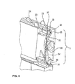
- Fig. 1 shows a first embodiment of an ink cartridge 10 for an inkjet printer in a side view.
- Fig. 2 is the ink cartridge off Fig. 1 shown from the front.
- the ink cartridge 10 is configured as a so-called "front loader" cartridge and has a front wall 11, a rear wall 12, a top wall 13, a bottom wall 14, a first side wall 15, and a second side wall 16.
- the ink cartridge is adapted to be inserted in the direction of the arrow 17 into an ink jet printer (not shown).
- an ink supply port 19 is provided in a lower portion 18 of the front wall 11.
- an opening 21 is provided which is provided with a lid 22 (made of rubber). is closed. Through the opening 21, the ink cartridge can be refilled.
- the opening 21 can also serve as an air inlet opening. Alternatively, the air inlet opening may be provided in the upper area of the cartridge (for example in the upper wall).
- Positioning members 23 to 28 on the top wall 13, the bottom wall 14, and the back wall 12 facilitate handling and insertion of the ink cartridge into the corresponding ink jet printer.
- the deflecting element 31 is in the embodiment according to the FIGS. 1 to 6 basically, as already in the WO 2011/035935 A1 , which originates from the Applicant described trained.
- the disclosure of the WO 2011/035935 A1 by reference in particular to Figures 2 and 3 , as well as related description) be part of the present application.
- An upper (first) light beam 32 (see Fig. 3 ) can meet perpendicular to an upper end 33 of an optical waveguide 34 and is reflected by internal reflection on the inclined surface 65 down in the direction of the deflection element 31 (see Figures 3 and 4 ).
- the course of the upper light beam 32 is drawn idealized after the reflection on the inclined surface.
- a (multiple) reflection on walls of the optical waveguide 34 can take place.
- a sealing layer 62 can additionally be provided at least on the oblique surface (see Fig.
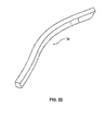
- FIG Fig. 22 A preferred embodiment of the optical waveguide 34 is shown in FIG Fig. 22 shown.
- the optical waveguide 34 according to Fig. 22 has a curved course and a rectangular cross-section.
- the optical waveguide 34 is part of a light guide device 36, the light from an upper light emitter (in the Figures 3 and 4 is not shown, but may be arranged at the level of the upper end 33 of the optical waveguide 34) down to a lower light receiver passes, which may be disposed at the height of the deflecting element 31 (also not in the Figures 3 and 4 shown).
- an upper (first) light entrance surface 37 and a light exit surface 38 have an offset V against each other.
- the offset V extends over the entire upper portion 30 of the front wall 11, that is (approximately) over the upper half of the front wall eleventh
- the light entry surface 37 is designed to guide a light beam of a light transmitter, which is directed perpendicular to the first side wall 15, through the optical waveguide 34 or the light guide device 36 in the direction of the second side wall 16, where it can exit perpendicularly in the direction of a lower light receiver 51 ,
- an upper light receiver will detect no or at least less light from the upper light transmitter, since (at least preferably) all the light from the light transmitter will be directed down through the optical waveguide 34.
- the upper light receiver can then be adjusted accordingly so that it detects an interruption of the light beam, for example when inserting the cartridge and in the inserted state and thus indicates a state "cartridge inserted" (if desired). This can be done, for example, by setting a load resistance or the like.
- the optical waveguide 34 is disposed at a front end 39 of the upper wall 13.
- the cap 35 is formed integrally with a guide rib 40 upstanding from the top wall 13.
- guide rib 40 and cap 35 may be formed as separate components.
- An upper 41 and lower 42 spacer serve in particular the support and fixation of the optical waveguide.
- the guide rib 40 and the cap 35 assumes a supporting function of the optical waveguide. Due to the integral formation of support rib 40 and cap 35 three different functions with only one component is taken into account (positioning function for the ink cartridge, support function for the ink cartridge and at the same time the optical fiber, reflection function of an inside of the cap 35). As a result, the design effort can be reduced. Furthermore, the light guide can also be held (only) by clamping action between guide rib 40 or cap 35 and prism 31.
- the optical waveguide 34 and the spacers 41, 42 are arranged in an empty (not filled with ink) space 43 and are (see Fig. 5 ) between the front wall 11 and an ink accommodating space 44.
- the space 43 with the optical waveguide 34 and the spacers 41, 42 is covered by a cover 45.
- a cover 45 At a lower end 46 of the optical waveguide 34 is an inclined surface (see Fig. 6 ), which may be mirrored for additional support of the internal reflection at an exit bevel arranged here. From the exit inclined surface of the upper light beam 32 (in this case, in a (approximately) 90 ° angle to the exit surface of the light guide) in the direction of the deflection element 31 and passed therethrough.
- the deflecting element 31 is designed and provided to produce a lower (second) light beam 48 from a lower (second) Leading entrance surface 49 to the light exit surface 38.
- the lower entrance surface 49 defines a light beam deflection surface.
- the light exit surface 38 lies opposite the lower (second) entrance surface 49.
- a light beam exits through the light exit surface 38 when a total reflection occurs within the light beam deflection element 31 (ie in the non-wetted state of the surface 53 of the deflection element 31 arranged in the ink chamber).
- the light emitter 50 and the light receiver 51 can be seen.
- Fig. 6 the light emitter 50 and the light receiver 51 can be seen.
- Fig. 21 is still a projection 76 which is associated with the deflecting element 31 to recognize.
- Fig. 21 corresponds (with changed reference numerals) the Fig. 3 from the publication WO 2011/035935 A1 (With regard to the deflection element 31 is in particular this Fig. 3 of the WO 2011/035935 A1 referenced).
- the light beam of the upper light transmitter can also be introduced directly (without a further inclined surface) into a correspondingly adapted fill level detection means.
- a possible beam path is shown in dashed lines.
- the (in Fig. 9 unrecognizable) optical fiber has a lower end surface which is (approximately) aligned perpendicular to the beam path.
- the light beam is introduced directly into a correspondingly adapted (asymmetrical) level detection means.
- the lower light entrance surface 49 and the light exit surface 38 act with a within the cartridge 10 depending on the level of 52 ink or ink 52 entsnetzbarer (horizontal) deflection surface 53 (the deflection 53 is in Fig. 6 drawn dashed, since it is actually only behind the front wall 11 is arranged) together.
- the lower light entry surface 49, the light exit surface 38 (in Fig. 6 not visible) and the deflection surface 53 are thus components of an integral component, namely the (approximately) U-shaped deflecting element 31 Fig.
- the two legs 54, 55 of the deflection element 31 enclose an angle of ⁇ 90 °, in particular (approximately) 35 ° to 50 °, preferably (approximately) 45 °. This angle depends on the material of the deflection element 31 and also the thickness and the length of the legs 54, 55. As Fig. 6 can recognize, define the two legs 54, 55 of the deflecting element 31 between the lower light entrance surface 49 and the light exit surface 38 each still at least one, specifically two further (inner) Lichtumlenk vom 57, 58 and 59, 60th
- Free ends of the two legs 54, 55 each include a deflection prism with outwardly directed tip.
- the respective tip or the respective deflection prism define in each case the light transmitter 50 and the light receiver 51 facing inclined surfaces, namely the lower light entrance surface 49 (deflection) and the light exit surface 38 (deflection).
- the deflection surfaces 57, 60 form inner light beam deflection surfaces.
- the light entry surface 49 and the deflection surface 57 or the deflection surface 60 and the light exit surface 38 of the end-side deflection prisms enclose an angle of (approximately) 35 ° to 60 °, in particular (approximately) 45 °. This angle may depend on the material of the deflecting element 31 and thus on the refractive index of the same.
- the information provided is intended to refer in particular to a polypropylene prism (other materials such as polycarbonate or PMMA materials are possible).
- the light transmitter 50 and the light receiver 51 facing surfaces 49, 38 in the cross section of the respectively associated deflection prisms are dimensioned shorter than the respective opposing deflection surfaces 57, 60. These dimensions also depend on the material of the deflection element 31 and thus of the corresponding Refractive index. It must be ensured that the light beam (safe) impinges on the respective inner deflection surfaces 57, 60.
- the legs 54, 55 of the deflecting element 31 are (preferably) an integral part of an ink receiving space.
- the legs 54, 55 and the interposed web 56 of the deflection element 31 are dimensioned so that the beam path in total reflection, ie remains at entnetzter deflection 53 within the two aforementioned legs and the aforementioned web portion.
- the entry and exit takes place only at the entrance surface 49 or light exit surface 38. Accordingly, the beam path can not be disturbed by external influences.
- the incoming light beam from the first outer entrance surface is deflected directly to the ink wettable surface and deflected in total reflection directly to the second outer light exit surface.
- the optical waveguide 34 is curved backwards. As a result, space can be created easily for further components, for example for a receptacle 61.
- the receptacle 61 can receive a projection (for example for a guide element) of the printer.
- a projection for example for a guide element
- the planar structure of the optical waveguide 34 can be seen.
- the upper end 33 of the optical waveguide is further forward than the lower end 46.
- the optical waveguide 34 thus also causes an offset W (see Fig. 5 ) relative to the insertion direction (or an offset W perpendicular to the offset V).
- This offset W (as well as the offset V) has the advantage that the transmitter and receiver of the upper light beam 32 can be arranged comparatively far apart from one another.
- the offset W to the rear there is the further advantage that the lower end 46 of the optical waveguide 34 is better protected (for example, from shocks or dirt) or can also be guided into the interior of the ink cartridge.
- the cross section of the optical waveguide 34 (see Fig. 3 and 4 ) is (substantially) rectangular, with a preferably at least in the upper region downwardly decreasing longitudinal side to direct the light beam during insertion and in the inserted state to the same exit surface of the cartridge. If, on the other hand, the light beam is to emerge at different locations of the cartridge during insertion and in the inserted state, an arrangement of two light guides arranged one behind the other with respect to the insertion direction may be advantageous, for example (see Fig. 12 ).
- the cartridge 10 has (roughly) a (flat) cuboid plan.
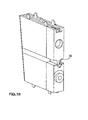
- Fig. 7 shows a second embodiment of an ink cartridge in an oblique view.
- the second embodiment is the same as the first embodiment (with the following differences).
- the first embodiment is at In the second embodiment, no cap 35 is provided, but a reflective mirror layer 62.
- This has a reflective function, such as the cap 35 of the first embodiment, if necessary, and is to deflect a light incident on the upper end 33 of the optical waveguide 34 downwards in the direction of deflecting element 31 ,
- the mirror layer 62 therefore optionally forms, like the inside of the cap 35, a light deflection surface.
- FIGS. 8 to 12 a third embodiment of the ink cartridge is shown. This differs from the first two embodiments in particular in that not only one, but two optical waveguides are provided, namely a front (first) optical waveguide 63 and a rear (second) optical waveguide 64 (see Fig. 12 ).
- the outer structure according to Fig. 8 is similar (in essence) to the external structure of the first two embodiments.
- the light guide device 36 deviates from the first two embodiments (see also FIG Fig. 10 ).
- the first 63 and second 64 optical waveguide of the third embodiment formed identical. Both optical waveguides 63, 64 are curved backwards and in a frontal view (see Fig. 11 ) just.
- An incident light beam (an upper light emitter) indicated here by A is reflected at an inclined surface 65 into the optical waveguide 63 (64) after being entered at the corresponding light entrance surface 37. From the upper end 33 of the optical waveguide 34, the light beam is guided by this to the lower end 46 of the optical waveguide.
- the light From the lower end 46, the light initially impinges vertically through an upper horizontal entrance surface of a deflecting prism 67, which in this case is asymmetric, and then strikes an inclined surface 66 of the deflecting prism. From the slant surface 66, the light beam is reflected (or not) depending on whether the slant surface 66 is wetted with ink or not. If no ink is present (ie, a reflection takes place), the light beam is directed in the direction of a further inclined surface 68. From there (when no ink is applied to the inclined surface 68), it is directed in the direction of a projection 69 with an inclined surface 70. From this projection 69, the light beam can be directed in the direction of a (lower) light emitter.
- a deflecting prism 67 which in this case is asymmetric
- the emerging at the light exit surface 38 light beam is marked B. It is possible to combine the third embodiment with the first or second. For example, in another embodiment, two optical fibers 63, 64 may be provided, which cooperate with a deflection element 31 according to the first and second embodiment.
- an air chamber 71 may be provided which bears against an outer surface 72 of the deflection prism 67. This ensures that the light of the first optical waveguide 63 is always deflected by the deflection prism 67 and can emerge at the light exit surface 38. Regardless of the wetting (or the level of the cartridge) is thus always redirected light (in this area).
- the air chamber 71 may extend over the entire outer surface of the prism 67 or even only in the region of coupling of the light from the second (rear) optical waveguide.
- a first detector 73 and a second detector 74 are shown schematically.
- the detectors 73, 74 should each consist of a light transmitter and a light receiver.
- the light emitter sends light perpendicular to the plane of the drawing Fig. 12 towards the receiver behind the drawing plane. If now the ink cartridge 10 is moved along the arrow 17, the light beams of the detectors 73, 74 are correspondingly interrupted (or diverted).
- the light beam of the lower detector 74 is (completely) blocked as soon as the front wall 11 enters the light beam. Upon further insertion of the light beam of the lower detector 74 is blocked by the ink cartridge 10.
- the light beam of the upper detector 73 is deflected downward as soon as the first optical waveguide 63 penetrates into the light beam. For the receiver of the upper detector 73 this is like a (complete) blocking. As soon as light of the upper detector 73 is deflected by the first optical fiber 63 (and later the second optical fiber 64), this light can be transmitted by the receiver of the lower detector 74 (depending on its position).
- the respective upper end 33 of the light guides 63, 64 may (in Fig. 12 back) through an opaque wall. This can ensure that the light of the upper detector 73, as soon as the front wall 11, the light beam of the upper detector 73 is prevented from reaching the upper light receiver.
- the in Fig. 14 detected signal.
- the upper curve is the signal received by the upper light receiver.
- the lower curve is the signal received by the lower light receiver.
- the upper curve is marked accordingly by the reference numeral 73 ', the lower curve by 74'.
- the front wall 11 of the ink cartridge enters the light beam of the lower detector 74.
- the front wall 11 enters the light beam of the upper detector 73.
- the first optical fiber 63 enters the light beam of the upper detector 73 and directs light down in the direction of the deflecting prism 67.
- the lower detector 74 thus receives light again (although the light beam of the light emitter of the lower detector 74 is still interrupted). Between times t4 and t5, the upper sensor 73 is located between the first optical fiber 63 and the second optical fiber 64. The lower sensor 74 is located between times t4 and t5 across a gap 75 between the lower ends 46 of the optical fibers 63, 64. Since the light beam of the lower detector 74 is also interrupted in this position by the cartridge wall (or other interrupting means) and the light of the optical fibers 63, 64 is passed past the gap 75, the lower detector 74 receives no light.
- the second light guide 64 thus forms a level detection means together with the deflection prism.
- the lower curve in Fig. 14 corresponds to the embodiment with the in Fig. 12 dashed air chamber. If this were omitted, then (in the filled state of the cartridge or wetting of the deflecting prism) would result in a signal interruption also between the times t3 and t4. Any wetting over the entire outer surface of the Prismas 67 prevented, as would always (and regardless of the level of the cartridge) in the lower curve of the Fig. 14 shown, solid course.
- Corresponding further signal curves for distinguishing between different types of cartridges or cartridge states can be generated by corresponding variations in the sequence of signal-conducting or signal-interrupting elements or corresponding element or cartridge sections in cooperation with the light emitters and light detectors (or particularly advantageously in the sense of FIG the invention with only one, in particular the upper detector, or additional lower sensor without second light emitter) can be realized.
- the projection 69 projects upwards (in the direction of the upper end 33 of the first optical waveguide 63) and extends to the optical waveguide 63 (approximately) antiparallel, Extending the projection 69, there is a (approximately) antiparallel extending third optical waveguide (which should also be marked with the reference numeral 69).
- first 63 or second 64 fiber optic cables there are still several alternatives for the first 63 or second 64 fiber optic cables.
- a shorter first optical waveguide 63 'could be provided or a (longer) third optical waveguide 69' or 69 "or 69"'.
- the capital letters A, A 'each indicate a possible incoming light beam.
- the capital letters B, B ', B "and B"' each indicate a possible outgoing light beam.
- a set of ink cartridges with first, second or third optical fibers of different lengths could easily make it possible to distinguish the ink cartridge.
- a plurality of detectors could be provided at different locations in the printer.
- the third optical waveguide 69 '" is not continuous, but consists of a plurality of sections divided by oblique surfaces be that they each reflected only a part of the light.
- an incoming light beam could be distributed to a plurality of exiting light beams.
- two incoming light rays could be combined by partially reflecting oblique surfaces, so that they emerge as a single beam of light.
- light beams A, A 'could be irradiated simultaneously and emerge again as light beam B'.
- a single light beam, namely A could enter and exit in the form of four different light beams B, B ', B "and B'".
- Fig. 15 a section of a further embodiment of the ink cartridge is shown.
- This embodiment corresponds to the first (or alternatively the second) embodiment, but with the deflection element 31 deviating from the first (or second) embodiment.
- the difference is that the (lower) light entry surface 49 is opaque, and / or the corresponding light emitter of the printer is missing.
- An opaque design means that the lower (second) light beam 48 is always interrupted by the deflection element 31 (regardless of whether the deflection surface 53 is wetted with liquid or not).
- the upper (first) light beam 32 as explained in the first or second embodiment, passed through the ink cartridge.
- the present fluid receptacle can be used as a tank, in particular a liquid tank, in which light signals can be deflected or coupled out.
- a deflection of a light beam in a hard to reach lower portion of a tank, in which a level indicator (for example, level prism) is arranged performed be returned to a sensor (light emitter or light receiver).
- prisms may be considered as fill level detection means, for example the prism described in detail with reference to the first and second embodiments or else a triangular prism (which is basically known in the prior art).
- a further light guide or a further light deflection to a return of a light beam can be advantageous.
- a deflection can be carried out in one piece, or be prepared by corresponding bonding of the individual components in order to prevent the in this case disturbing gaps between the components.
- a basic idea is to multiply use the signal of a single detector (on the one hand, to prevent a light signal from reaching the receiver of a first detector and, on the other hand, to allow the same signal to be redirected to a second light receiver). As a result, different signal sequences can be realized with only one light source.
- a level detection can also be provided, for example, at the lowest point of a reservoir.
- an upper sensor can be used as a signal generator.
- the upper sensor often has a stronger and therefore a secure signal. If this stronger signal is used to make the lower sensor responsive, for example, the detection of the cartridge (and the ink level) becomes safer.
- the optical fiber (s) may be constructed and placed to allow desired bursts of signal to be detected by a cartridge in the respective ink jet printer.
- the optical fibers are preferably made of polycarbonate (for example, by injection molding), although other materials may be used such as: PMMA, fiberglass, glass, other transparent, photoconductive materials.
- the optical fiber may have bends and curves. Preferably However, a minimum bending or deflection radius of 2 mm is not exceeded.
- the proposed design also serves to avoid recognition problems when inserting ink cartridges (fluid receiving containers), in particular signal sequences and / or signal strength can be ensured in a more reliable manner.
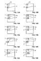
- Fig. 15A shows an ink cartridge in a schematic view and a first signal receiver 1 and a second signal receiver 2.
- the signal receiver 1, 2 are in the FIGS. 15A to 19B shown as circles. They should be oriented in such a way that they emit light perpendicular to the plane of the drawing FIGS. 15A to 19B (ie perpendicular to the side wall of the cartridge) runs, can detect.
- the signal receiver 1 a corresponding signal generator is provided which is aligned in a direction perpendicular to the drawing plane with the signal receiver 1.
- the in the FIGS. 15A to 19B shown cartridges comprise an optical waveguide 34 and a level indicator 4.
- FIGS. 15A to 19B shown cartridges comprise an optical waveguide 34 and a level indicator 4.
- FIGS. 15A to 19B is still each next to the first and second light receiver, a third light receiver 3 is provided.
- the Figures 15A, 16A, 17A, 18A and 19A should each show the condition of the cartridge during insertion.
- the Figures 15B, 16B, 17B, 18B and 19B should each show the state of the cartridge in the inserted state. The insertion is thus in the FIGS. 15A to 19B from right to left (with stationary trained signal receivers 1, 2, 3).
- FIGS. 15A and 15B show a structurally comparatively simple embodiment of an ink cartridge.
- the signal receivers 1, 2 are located above the front wall of the ink cartridge. This may possibly consist of a fundamentally opaque material. With a corresponding adjustment of the light receiver, however, a front wall which basically consists of a light-transmissive material can be detected (for this, if appropriate, corresponding load resistances would have to be regulated, etc.).
- the level detection means 4 is in the light path of the light of the light emitter. Depending on the level, the light is now transmitted or blocked, so that the level can be detected.
- the light receiver 2 and the level detection means 4 are arranged here (essentially) in the middle. However, a different arrangement is conceivable (for example, below).
- the light path can be set such that both light receivers 1, 2 receive a signal depending on the level of the ink cartridge.
- the light of the transmitter is completely conducted to light receiver 2, so that the light receiver 1 is blocked when the light guide is in the light barrier.
- FIGS. 16A, 16B corresponds to the embodiment according to the FIGS. 15A, 15B with the exception that the optical waveguide 34 is offset to the rear.
- the optical waveguide 34 is offset to the rear.
- the position of the retainer between the cartridge and the light receiver 1, 2 according to FIG Fig. 16A For example, by an opaque side wall of the cartridge, the light of the light emitter is blocked, so that the light receiver 1, 2 can not receive a signal.
- the relative position according to Fig. 16B is the light emitter opposite the entrance surface of the optical waveguide 34 so that it can introduce light into it. The light is directed down to the light receiver 2 (via the level detection means 4).
- the light receiver 1 thus receives no light.
- the light receiver 2 receives depending on the level of light or no light.
- FIGS. 17A, 17B an embodiment is shown which basically generates the same signals as the FIGS. 16A, 16B ,
- the optical waveguide 34 is formed widening in the direction of the first light receiver 1.
- the transmitter is already opposite the entrance surface of the optical waveguide 34, so that light is directed downwards in the direction of level detection means 4 and no light can reach the first light receiver 1.
- the light receiver 2 is still ahead of the level detection means 4, so that it can not detect the downwardly guided light.
- neither the first light receiver 1 nor the second light receiver 2 receives a signal in this position.
- the light emitter continues to conduct light towards the level detection means 4.
- Figs. 15A to 17B light receivers are shown, which are arranged at the same height relative to the insertion direction (from right to left). Furthermore, only two light receivers 1, 2 are always provided.
- FIG. 18B shows an embodiment which also shows an optical waveguide 34 which widens in the direction of light emitter 1 (upward).
- a third light receiver 3 is provided in addition to the first and second light receivers 1, 2, a third light receiver 3 is provided.
- the third light receiver 3 is located at the same level (relative to the insertion direction) as the first light receiver 1.
- the second light receiver 2 is located offset from the first and third light receivers 1, 3 to the front.
- the light transmitter is already opposite the entrance surface of the optical waveguide 34, so that light is directed down and the upper light receiver no longer receives light.
- the second light receiver also does not receive light, as in the embodiments of FIGS. 15A to 19B only one light transmitter (at the light receiver 1) is provided.
- the third light receiver 3 receives level dependent light or no light.
- the light transmitter is further opposite the entrance surface of the optical waveguide 34, so that light is directed downwards and the first light receiver 1 receives no light.
- the second light receiver 2 is now opposite the exit surface of the level detection means 4 and a light guide and receives (depending on the level) light or no light.
- the third light receiver 3 is now already behind the level detection means 4 and the optical waveguide 34 and receives no light.
- FIGS. 19A, 19B One to the FIGS. 18A, 18B similar embodiment is in the FIGS. 19A, 19B shown.
- the first and second light receiver In the position according to Fig. 19A is the first and second light receiver at the same height and the third light receiver 3 with respect to the first and second light receiver 1, 2 offset to the rear (relative to the insertion direction).
- the light transmitter In the position according to Fig. 19A the light transmitter is already above the optical waveguide, so that light is introduced into the optical waveguide and no light arrives at the first light receiver 1.
- the second light receiver 2 is still in front of the level detection means 4 and the optical waveguide 34 and also receives no light.
- the third light receiver 3 is opposite to the exit surface of the level detection means 4 and a third light guide 34 and thus receives (level dependent) light or no light.
- Fig. 19A In the position according to Fig. 19A is the first and second light receiver at the same height and the third light receiver 3 with respect to the first and second light receiver 1, 2
- the light transmitter is still opposite the entrance surface the widened portion of the optical waveguide 34 and introduces light in this.
- the first signal receiver 1 reaches no light.
- the second light receiver 2 is in this position above the level detection means 4 and the optical waveguide 34 and receives (depending on the level) light or no light.
- the third light receiver 3 is already behind the level detection means 4 and the optical waveguide 34 and therefore also receives no light.
- the embodiments act according to Figs. 18A, 18B and according to Figs. 19A, 19B in the same way.
- Fig. 20A shows a front view of an ink cartridge according to the prior art.
- a signal blocking element 5 On the front wall of the ink cartridge shown a signal blocking element 5 is shown.
- a light emitter 50 is arranged on the front wall of the ink cartridge.
- a light receiver 51 is arranged on the front wall of the ink cartridge.
- Fig. 20B is a front view of an embodiment of the ink cartridge according to the invention shown.
- the light emitter 50 and the light receiver 51 do not align (with respect to the direction of the exiting light beam), but have a (considerable) offset.
- an optical waveguide 34 is provided. Will thus light (as in Fig. 20B ) is not blocked by a signal blocking element 5, it can be detected by the light receiver 51.
- Light transmitter 50 and light receiver 51 are assigned to the same side wall of the ink cartridge.
- Fig. 20C shows a schematic front view of an ink cartridge according to the invention, which, as the embodiment according to Fig. 20B , a (comparatively large) offset between the light transmitter 50 and light receiver 51 allows.
- light emitters 50 and light emitters 51 are associated with opposite side walls.
- the optical waveguide 34 is compared to an embodiment according to Fig. 20B modified accordingly and has a (partially) curved course.
- the upper and lower inclined surfaces are parallel to each other.
- the upper and lower oblique surfaces are perpendicular to each other.
Landscapes
- Health & Medical Sciences (AREA)
- General Health & Medical Sciences (AREA)
- Life Sciences & Earth Sciences (AREA)
- Pain & Pain Management (AREA)
- Physical Education & Sports Medicine (AREA)
- Rehabilitation Therapy (AREA)
- Epidemiology (AREA)
- Animal Behavior & Ethology (AREA)
- Dermatology (AREA)
- Public Health (AREA)
- Veterinary Medicine (AREA)
- Nursing (AREA)
- Ink Jet (AREA)
Applications Claiming Priority (1)
| Application Number | Priority Date | Filing Date | Title |
|---|---|---|---|
| DE102012005981A DE102012005981A1 (de) | 2012-03-23 | 2012-03-23 | Fluidaufnahmebehälter, insbesondere Tintenpatrone, für Tintenstrahldrucker |
Publications (1)
| Publication Number | Publication Date |
|---|---|
| EP2641742A2 true EP2641742A2 (fr) | 2013-09-25 |
Family
ID=47748479
Family Applications (1)
| Application Number | Title | Priority Date | Filing Date |
|---|---|---|---|
| EP13155919.7A Withdrawn EP2641742A2 (fr) | 2012-03-23 | 2013-02-20 | Récipient collecteur de liquide, en particulier cartouche d'encre, pour imprimante à jet d'encre |
Country Status (2)
| Country | Link |
|---|---|
| EP (1) | EP2641742A2 (fr) |
| DE (2) | DE102012005981A1 (fr) |
Cited By (1)
| Publication number | Priority date | Publication date | Assignee | Title |
|---|---|---|---|---|
| CN113168449A (zh) * | 2018-12-03 | 2021-07-23 | 惠普发展公司,有限责任合伙企业 | 打印液体供应单元 |
Citations (6)
| Publication number | Priority date | Publication date | Assignee | Title |
|---|---|---|---|---|
| EP0573274A2 (fr) | 1992-06-03 | 1993-12-08 | Canon Kabushiki Kaisha | Dispositif de détection de la quantité d'encre et appareil d'enregistrement muni d'un tel dispositif |
| EP0626267A2 (fr) | 1993-05-26 | 1994-11-30 | Canon Kabushiki Kaisha | Appareil d'enregistrement par jet d'encre |
| EP0779156A1 (fr) | 1995-12-14 | 1997-06-18 | Xerox Corporation | Système pour détecter la présence d'une cartouche d'encre et son niveau d'encre |
| DE102007001084A1 (de) | 2006-12-12 | 2008-06-19 | Pelikan Hardcopy Production Ag | Tintenpatrone für Tintenstrahldrucker |
| DE202008017958U1 (de) | 2008-02-28 | 2010-12-23 | BROTHER KOGYO K.K., Nagoya-shi | Tintenpatrone, Satz von Tintenpatronen und Tintenpatronenbestimmungssystem |
| WO2011035935A1 (fr) | 2009-09-28 | 2011-03-31 | Pelikan Hardcopy Production Ag | Cartouche d'encre pour imprimante à jet d'encre |
Family Cites Families (4)
| Publication number | Priority date | Publication date | Assignee | Title |
|---|---|---|---|---|
| US6097405A (en) * | 1996-09-30 | 2000-08-01 | Hewlett-Packard Company | Detection apparatus and method for use in a printing device |
| JP2007245637A (ja) * | 2006-03-17 | 2007-09-27 | Canon Inc | 液体収納容器 |
| US7950791B2 (en) * | 2007-10-29 | 2011-05-31 | Hewlett-Packard Development Company, L.P. | Ink level detection by electronic means |
| DE202010001899U1 (de) * | 2010-01-28 | 2010-05-06 | Dynamic Cassette International Ltd., Boston | Tintenpatrone |
-
2012
- 2012-03-23 DE DE102012005981A patent/DE102012005981A1/de not_active Withdrawn
- 2012-03-23 DE DE202012003737U patent/DE202012003737U1/de not_active Expired - Lifetime
-
2013
- 2013-02-20 EP EP13155919.7A patent/EP2641742A2/fr not_active Withdrawn
Patent Citations (6)
| Publication number | Priority date | Publication date | Assignee | Title |
|---|---|---|---|---|
| EP0573274A2 (fr) | 1992-06-03 | 1993-12-08 | Canon Kabushiki Kaisha | Dispositif de détection de la quantité d'encre et appareil d'enregistrement muni d'un tel dispositif |
| EP0626267A2 (fr) | 1993-05-26 | 1994-11-30 | Canon Kabushiki Kaisha | Appareil d'enregistrement par jet d'encre |
| EP0779156A1 (fr) | 1995-12-14 | 1997-06-18 | Xerox Corporation | Système pour détecter la présence d'une cartouche d'encre et son niveau d'encre |
| DE102007001084A1 (de) | 2006-12-12 | 2008-06-19 | Pelikan Hardcopy Production Ag | Tintenpatrone für Tintenstrahldrucker |
| DE202008017958U1 (de) | 2008-02-28 | 2010-12-23 | BROTHER KOGYO K.K., Nagoya-shi | Tintenpatrone, Satz von Tintenpatronen und Tintenpatronenbestimmungssystem |
| WO2011035935A1 (fr) | 2009-09-28 | 2011-03-31 | Pelikan Hardcopy Production Ag | Cartouche d'encre pour imprimante à jet d'encre |
Cited By (2)
| Publication number | Priority date | Publication date | Assignee | Title |
|---|---|---|---|---|
| CN113168449A (zh) * | 2018-12-03 | 2021-07-23 | 惠普发展公司,有限责任合伙企业 | 打印液体供应单元 |
| US11787194B2 (en) | 2018-12-03 | 2023-10-17 | Hewlett-Packard Development Company, L.P. | Sealed interconnects |
Also Published As
| Publication number | Publication date |
|---|---|
| DE102012005981A1 (de) | 2013-09-26 |
| DE202012003737U1 (de) | 2012-04-25 |
Similar Documents
| Publication | Publication Date | Title |
|---|---|---|
| EP1147902B1 (fr) | Méthode pour détecter le niveau d'un liquide dans un réservoir | |
| DE112005003837B4 (de) | Flüssigkeitsspeicherbehälter und Tintenstrahlaufzeichnungsgerät | |
| EP0523521B1 (fr) | Appareil de mesure de radiations, en particulier pour la mesure de la luminescence | |
| DE60035868T2 (de) | Drucker | |
| EP2356432B1 (fr) | Ensemble capteur | |
| EP0450174B1 (fr) | Dispositif de mesurage opto-électrique du niveau d'interface et de l'indice de réfraction dans des fluides | |
| DE68915141T2 (de) | Immuntestvorrichtung. | |
| DE102007036492A1 (de) | Optische Sensorvorrichtung | |
| DE3247659A1 (de) | Optischer sensor | |
| DE202011001702U1 (de) | Detektor und mobiler Automat mit demselben | |
| AT510750A1 (de) | Messanordnung zur quantitativen optischen auswertung einer chemischen reaktion | |
| EP2641742A2 (fr) | Récipient collecteur de liquide, en particulier cartouche d'encre, pour imprimante à jet d'encre | |
| CH695957A5 (de) | Vorrichtung zur Verfolgung eines sich bewegenden linearen Textilgebildes, besonders eines Garnes. | |
| DE3525264C2 (fr) | ||
| EP2270435A2 (fr) | Doigt de capteur optique | |
| EP0450175B1 (fr) | Dispositif d'indication opto-électrique du niveau d'un liquide | |
| EP2686664B1 (fr) | Détection de milieux optiques plans en au moins deux couches à séparation optique | |
| EP2483080B1 (fr) | Cartouche d'encre pour imprimante à jet d'encre | |
| WO2011035935A1 (fr) | Cartouche d'encre pour imprimante à jet d'encre | |
| DE102009041650A1 (de) | Tintenpatrone mit Elementen für Füllstandsdetektion | |
| DE202010017253U1 (de) | Tintenpatrone und Tintenstrahldrucker zur Aufnahme einer solchen Tintenpatrone | |
| DE202009007358U1 (de) | Tintenkartusche | |
| EP3554985B1 (fr) | Machine de remplissage permettant de remplir des récipients | |
| DE29624275U1 (de) | Fühlersystem zur Erfassung der Anwesenheit eines Tintenbehälters und des Tintenfüllstandes darin | |
| DE10117885A1 (de) | Tintendrucker mit einem Tintenversorgungssystem |
Legal Events
| Date | Code | Title | Description |
|---|---|---|---|
| PUAI | Public reference made under article 153(3) epc to a published international application that has entered the european phase |
Free format text: ORIGINAL CODE: 0009012 |
|
| AK | Designated contracting states |
Kind code of ref document: A2 Designated state(s): AL AT BE BG CH CY CZ DE DK EE ES FI FR GB GR HR HU IE IS IT LI LT LU LV MC MK MT NL NO PL PT RO RS SE SI SK SM TR |
|
| AX | Request for extension of the european patent |
Extension state: BA ME |
|
| RAP1 | Party data changed (applicant data changed or rights of an application transferred) |
Owner name: PELIKAN HARDCOPY PRODUCTION AG |
|
| STAA | Information on the status of an ep patent application or granted ep patent |
Free format text: STATUS: THE APPLICATION IS DEEMED TO BE WITHDRAWN |
|
| 18D | Application deemed to be withdrawn |
Effective date: 20180901 |