EP2641827A2 - Véhicule marin avec dispositif d'amplification de poussée - Google Patents
Véhicule marin avec dispositif d'amplification de poussée Download PDFInfo
- Publication number
- EP2641827A2 EP2641827A2 EP13160413.4A EP13160413A EP2641827A2 EP 2641827 A2 EP2641827 A2 EP 2641827A2 EP 13160413 A EP13160413 A EP 13160413A EP 2641827 A2 EP2641827 A2 EP 2641827A2
- Authority
- EP
- European Patent Office
- Prior art keywords
- propeller
- fin member
- hull
- rotational axis
- end portion
- Prior art date
- Legal status (The legal status is an assumption and is not a legal conclusion. Google has not performed a legal analysis and makes no representation as to the accuracy of the status listed.)
- Withdrawn
Links
- 230000001141 propulsive effect Effects 0.000 description 3
- 230000021715 photosynthesis, light harvesting Effects 0.000 description 2
- 239000012530 fluid Substances 0.000 description 1
- 238000011144 upstream manufacturing Methods 0.000 description 1
Images



Classifications
-
- B—PERFORMING OPERATIONS; TRANSPORTING
- B63—SHIPS OR OTHER WATERBORNE VESSELS; RELATED EQUIPMENT
- B63H—MARINE PROPULSION OR STEERING
- B63H5/00—Arrangements on vessels of propulsion elements directly acting on water
- B63H5/07—Arrangements on vessels of propulsion elements directly acting on water of propellers
- B63H5/16—Arrangements on vessels of propulsion elements directly acting on water of propellers characterised by being mounted in recesses; with stationary water-guiding elements; Means to prevent fouling of the propeller, e.g. guards, cages or screens
-
- B—PERFORMING OPERATIONS; TRANSPORTING
- B63—SHIPS OR OTHER WATERBORNE VESSELS; RELATED EQUIPMENT
- B63B—SHIPS OR OTHER WATERBORNE VESSELS; EQUIPMENT FOR SHIPPING
- B63B1/00—Hydrodynamic or hydrostatic features of hulls or of hydrofoils
- B63B1/32—Other means for varying the inherent hydrodynamic characteristics of hulls
Definitions
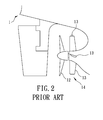
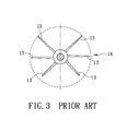
- the propeller 12 Due to the working mechanism of the propeller 12 and ship hull, the propeller 12 produces a lot of turbulence and energy dissipation while generating the propulsive force. If the rotationalal speed of the propeller 12 is increased, more turbulence and energy dissipation will result, thereby failing to enhance propulsion and speed of the marine vehicle 1.
- the marine vehicle of the present invention comprises a hull, a propeller mounted to the hull and rotatable about a rotational axis, and a thrust boosting device mounted to the hull and disposed forwardly of the propeller with respect to a bow of the hull.
- a reference line extends upwardly from and is perpendicular to the rotational axis of the propeller.
- the thrust boosting device 2 is mounted to the hull 210 and is disposed forwardly of the propeller 201 with respect to the bow 205.
- the thrust boosting device 2 includes a first fin member 21 disposed on the starboard side 202, a second fin member 22 disposed on the port side 203 and a third fin member 23 disposed on the port side 203.
- Each of the first, second and third fin members (21, 22, 23) extends radially with respect to the rotational axis (L) of the propeller 201.
- a distance (T) between the thrust boosting device 2 and the propeller 201 along the rotational axis (L) is 0.2 to 2 times a diameter (D) of the propeller 201.
- the first fin member 21 forms a first angle ( ⁇ 1) in a clockwise direction with the reference line (S)
- the second fin member 22 forms a second angle ( ⁇ 2) in the clockwise direction with the reference line (S)
- the third fin member 23 forms a third angle ( ⁇ 3) in the clockwise direction with the reference line (S), all viewed from the stern 204.
- the first angle ( ⁇ 1) ranges between 70° and 110°
- the second angle ( ⁇ 2) ranges between 225° and 255°
- the third angle ( ⁇ 3) ranges between 285° and 315°.
- each of a distance (H1) between the first free end portion 212 of the first fin member 21 and the rotational axis (L) of the propeller 201, a distance (H2) between the second free endportion 222 of the second fin member 22 and the rotational axis (L) of the propeller 201, and a distance (H3) between the third free end portion 232 of the third fin member 23 and the rotational axis (L) of the propeller 201 is 1 to 1.2 times a radius (R) of the propeller 201.
- the distance (T) between the thrust boosting device 2 and the propeller 201 along the rotational axis (L) is 0.2 times the diameter (D) of the propeller 201.
- the first angle ( ⁇ 1) formed by the first fin member 21 in the clockwise direction with the reference line (S) is 90°
- the second angle ( ⁇ 2) formed by the second fin member 22 in the clockwise direction with the reference line (S) is 230°
- the third angle ( ⁇ 3) formed by the third fin member 23 in the clockwise direction with the reference line (S) is 300°.
- the ship speed of the experimental group provided with the thrust boosting device 2 is higher than the ship speed of the control group without the thrust boosting device 2 when provided with the same horsepower.
- the required horsepower of the experimental group provided with the thrust boosting device 2 is 5% lower than the required horsepower of the control group without the thrust boosting device 2 when moving at the same ship speed.
- the propeller exciting force of the experimental group is lower than the propeller exciting force of the control group.
- the second preferred embodiment of the thrust boosting device 2 of the present invention is similar to the first preferred embodiment.
- the thrust boosting device 2 further includes a plurality of tip appendages 24 disposed respectively on the first free end portion 212 of the first fin member 21, the second free end portion 222 of the second fin member 22 and the third free end portion 232 of the third fin member 23.
- the tip appendages 24 may alleviate tip vortex caused by the flow leaking from high pressure to low pressure near the free end portions 212, 222, 232 of the fin member 2.
- the tip appendage 24 may have a shape of an elliptic streamline as shown in Figure 14 and Figure 15 , a plate as shown in Figure 16 and Figure 17 , or a curved plate as shown in Figure 18 and Figure 19 .
- the present invention should not be limited to the second preferred embodiment.
- the present invention utilizes the first fin member 21, the second fin member 22 and the third fin member 23 of the thrust boosting device 2 to change the upstream flow field of the propeller 201 before fluid flows past the propeller 201 so as to reduce the eddy kinetic energy.
- This invention not only is low cost and low in complexity, but also is able to alleviate propeller exciting force and cavitation on the surface of the propeller 201, as well as to improve the propulsion efficiency and speed of the marine vehicle 200.
Landscapes
- Chemical & Material Sciences (AREA)
- Engineering & Computer Science (AREA)
- Combustion & Propulsion (AREA)
- Mechanical Engineering (AREA)
- Ocean & Marine Engineering (AREA)
- Physics & Mathematics (AREA)
- Fluid Mechanics (AREA)
- Structures Of Non-Positive Displacement Pumps (AREA)
- Sliding-Contact Bearings (AREA)
- Other Liquid Machine Or Engine Such As Wave Power Use (AREA)
- Support Of The Bearing (AREA)
Applications Claiming Priority (1)
| Application Number | Priority Date | Filing Date | Title |
|---|---|---|---|
| TW101110112A TW201339052A (zh) | 2012-03-23 | 2012-03-23 | 船舶的非對稱鰭翼裝置 |
Publications (2)
| Publication Number | Publication Date |
|---|---|
| EP2641827A2 true EP2641827A2 (fr) | 2013-09-25 |
| EP2641827A3 EP2641827A3 (fr) | 2017-05-24 |
Family
ID=47901870
Family Applications (1)
| Application Number | Title | Priority Date | Filing Date |
|---|---|---|---|
| EP13160413.4A Withdrawn EP2641827A3 (fr) | 2012-03-23 | 2013-03-21 | Véhicule marin avec dispositif d'amplification de poussée |
Country Status (4)
| Country | Link |
|---|---|
| EP (1) | EP2641827A3 (fr) |
| JP (1) | JP2013199272A (fr) |
| KR (1) | KR20130108142A (fr) |
| TW (1) | TW201339052A (fr) |
Cited By (2)
| Publication number | Priority date | Publication date | Assignee | Title |
|---|---|---|---|---|
| CN104828226A (zh) * | 2015-04-21 | 2015-08-12 | 中国船舶工业集团公司第七〇八研究所 | 一种船舶水动力辅助推进节能装置 |
| CN106184607A (zh) * | 2016-07-11 | 2016-12-07 | 广州文冲船厂有限责任公司 | 一种艉柱与尾鳍的安装结构 |
Families Citing this family (3)
| Publication number | Priority date | Publication date | Assignee | Title |
|---|---|---|---|---|
| WO2016064091A1 (fr) * | 2014-10-24 | 2016-04-28 | 삼성중공업 주식회사 | Dispositif d'amélioration de l'efficacité de propulsion |
| JP6704303B2 (ja) * | 2016-06-22 | 2020-06-03 | 三菱重工業株式会社 | リアクションフィン装置 |
| JP7375077B2 (ja) * | 2022-03-22 | 2023-11-07 | ジャパンマリンユナイテッド株式会社 | 船尾付加構造及び船舶 |
Citations (1)
| Publication number | Priority date | Publication date | Assignee | Title |
|---|---|---|---|---|
| CN1048461A (zh) | 1989-06-27 | 1991-01-09 | 松下电器产业株式会社 | 记录装置和再生装置 |
Family Cites Families (5)
| Publication number | Priority date | Publication date | Assignee | Title |
|---|---|---|---|---|
| DE3615619A1 (de) * | 1985-06-24 | 1987-01-02 | Schiffbau Veb K | Leiteinrichtung zur beeinflussung der propellerzustroemung bei schiffen |
| JP2948413B2 (ja) * | 1991-11-14 | 1999-09-13 | 三菱重工業株式会社 | 船舶用リアクションフィン装置 |
| JP5081455B2 (ja) * | 2007-01-19 | 2012-11-28 | 大宇造船海洋株式会社 | 船舶の非対称前流固定翼 |
| DE202009009899U1 (de) * | 2009-07-23 | 2010-12-02 | Becker Marine Systems Gmbh & Co. Kg | Düsenpropeller für Schiffe |
| CN102381463B (zh) * | 2011-08-17 | 2013-11-27 | 上海船舶研究设计院 | 桨前反应鳍 |
-
2012
- 2012-03-23 TW TW101110112A patent/TW201339052A/zh not_active IP Right Cessation
-
2013
- 2013-03-19 KR KR1020130029224A patent/KR20130108142A/ko not_active Ceased
- 2013-03-21 EP EP13160413.4A patent/EP2641827A3/fr not_active Withdrawn
- 2013-03-22 JP JP2013060658A patent/JP2013199272A/ja active Pending
Patent Citations (1)
| Publication number | Priority date | Publication date | Assignee | Title |
|---|---|---|---|---|
| CN1048461A (zh) | 1989-06-27 | 1991-01-09 | 松下电器产业株式会社 | 记录装置和再生装置 |
Cited By (2)
| Publication number | Priority date | Publication date | Assignee | Title |
|---|---|---|---|---|
| CN104828226A (zh) * | 2015-04-21 | 2015-08-12 | 中国船舶工业集团公司第七〇八研究所 | 一种船舶水动力辅助推进节能装置 |
| CN106184607A (zh) * | 2016-07-11 | 2016-12-07 | 广州文冲船厂有限责任公司 | 一种艉柱与尾鳍的安装结构 |
Also Published As
| Publication number | Publication date |
|---|---|
| TW201339052A (zh) | 2013-10-01 |
| JP2013199272A (ja) | 2013-10-03 |
| EP2641827A3 (fr) | 2017-05-24 |
| KR20130108142A (ko) | 2013-10-02 |
| TWI488772B (fr) | 2015-06-21 |
Similar Documents
| Publication | Publication Date | Title |
|---|---|---|
| TW200938434A (en) | Device for reducing the drive power requirement of a ship | |
| EP2641827A2 (fr) | Véhicule marin avec dispositif d'amplification de poussée | |
| CN103991508B (zh) | 双轴船尾双体船舶 | |
| JP2007535440A5 (fr) | ||
| JP2010195153A (ja) | 船舶用リアクションフィン装置および船舶 | |
| CN101626950A (zh) | 安全螺旋桨 | |
| EP2110311A3 (fr) | Gouverne à ailettes | |
| JP6548062B2 (ja) | 船尾用ダクト、船尾用付加物、船尾用ダクトの設計方法、及び船尾用ダクトを装備した船舶 | |
| JP4909380B2 (ja) | 船舶 | |
| CN204056274U (zh) | 船舶桨前节能附体结构 | |
| JP2010505683A (ja) | 船の側方方向舵 | |
| WO2011102103A1 (fr) | Propulseur comportant un conduit attaché et véhicule comprenant ce propulseur | |
| KR101225169B1 (ko) | 추진장치 및 이를 구비한 선박 | |
| JP2015127179A (ja) | ダクト装置 | |
| KR200480863Y1 (ko) | 선박용 프로펠러 | |
| KR101159205B1 (ko) | 선박용 방향타 및 이를 포함하는 선박 | |
| KR20140131725A (ko) | 선미 핀이 장착된 선박 | |
| KR20150030420A (ko) | 링형 캡 핀 및 그 캡 핀을 구비하는 프로펠러 | |
| WO2018020749A1 (fr) | Navire | |
| JPS6226197A (ja) | 船舶の推進性能向上装置 | |
| CN103387037B (zh) | 船舶的非对称y字形鳍翼装置 | |
| KR20130098943A (ko) | 선박 추진에 필요한 파워 요구를 감소시키기 위한 장치 | |
| KR102117384B1 (ko) | 선박용 덕트의 지지구조 | |
| WO2016166574A1 (fr) | Propulseur marin sans lame | |
| RU104536U1 (ru) | Судовой движитель |
Legal Events
| Date | Code | Title | Description |
|---|---|---|---|
| PUAI | Public reference made under article 153(3) epc to a published international application that has entered the european phase |
Free format text: ORIGINAL CODE: 0009012 |
|
| AK | Designated contracting states |
Kind code of ref document: A2 Designated state(s): AL AT BE BG CH CY CZ DE DK EE ES FI FR GB GR HR HU IE IS IT LI LT LU LV MC MK MT NL NO PL PT RO RS SE SI SK SM TR |
|
| AX | Request for extension of the european patent |
Extension state: BA ME |
|
| PUAL | Search report despatched |
Free format text: ORIGINAL CODE: 0009013 |
|
| AK | Designated contracting states |
Kind code of ref document: A3 Designated state(s): AL AT BE BG CH CY CZ DE DK EE ES FI FR GB GR HR HU IE IS IT LI LT LU LV MC MK MT NL NO PL PT RO RS SE SI SK SM TR |
|
| AX | Request for extension of the european patent |
Extension state: BA ME |
|
| RIC1 | Information provided on ipc code assigned before grant |
Ipc: B63H 5/16 20060101AFI20170419BHEP |
|
| STAA | Information on the status of an ep patent application or granted ep patent |
Free format text: STATUS: THE APPLICATION IS DEEMED TO BE WITHDRAWN |
|
| 18D | Application deemed to be withdrawn |
Effective date: 20171125 |