EP2642010A1 - Nähmaschine - Google Patents
Nähmaschine Download PDFInfo
- Publication number
- EP2642010A1 EP2642010A1 EP13160689.9A EP13160689A EP2642010A1 EP 2642010 A1 EP2642010 A1 EP 2642010A1 EP 13160689 A EP13160689 A EP 13160689A EP 2642010 A1 EP2642010 A1 EP 2642010A1
- Authority
- EP
- European Patent Office
- Prior art keywords
- stepping
- movement
- variable resistor
- amount
- foot controller
- Prior art date
- Legal status (The legal status is an assumption and is not a legal conclusion. Google has not performed a legal analysis and makes no representation as to the accuracy of the status listed.)
- Granted
Links
- 238000009958 sewing Methods 0.000 title claims abstract description 47
- 230000008859 change Effects 0.000 claims abstract description 5
- 238000006073 displacement reaction Methods 0.000 claims description 2
- 230000005540 biological transmission Effects 0.000 description 8
- 230000007246 mechanism Effects 0.000 description 8
- 230000008878 coupling Effects 0.000 description 3
- 238000010168 coupling process Methods 0.000 description 3
- 238000005859 coupling reaction Methods 0.000 description 3
- NCGICGYLBXGBGN-UHFFFAOYSA-N 3-morpholin-4-yl-1-oxa-3-azonia-2-azanidacyclopent-3-en-5-imine;hydrochloride Chemical compound Cl.[N-]1OC(=N)C=[N+]1N1CCOCC1 NCGICGYLBXGBGN-UHFFFAOYSA-N 0.000 description 2
- 229930040373 Paraformaldehyde Natural products 0.000 description 2
- 238000006243 chemical reaction Methods 0.000 description 2
- 230000006835 compression Effects 0.000 description 2
- 238000007906 compression Methods 0.000 description 2
- 230000009191 jumping Effects 0.000 description 2
- 229920006324 polyoxymethylene Polymers 0.000 description 2
- 230000003321 amplification Effects 0.000 description 1
- 230000000694 effects Effects 0.000 description 1
- 238000000034 method Methods 0.000 description 1
- 238000003199 nucleic acid amplification method Methods 0.000 description 1
- -1 polyoxymethylene Polymers 0.000 description 1
- 230000008569 process Effects 0.000 description 1
- 239000011347 resin Substances 0.000 description 1
- 229920005989 resin Polymers 0.000 description 1
Images


Classifications
-
- D—TEXTILES; PAPER
- D05—SEWING; EMBROIDERING; TUFTING
- D05B—SEWING
- D05B69/00—Driving-gear; Control devices
- D05B69/02—Mechanical drives
- D05B69/06—Pedal drives
-
- D—TEXTILES; PAPER
- D05—SEWING; EMBROIDERING; TUFTING
- D05B—SEWING
- D05B69/00—Driving-gear; Control devices
- D05B69/14—Devices for changing speed or for reversing direction of rotation
- D05B69/18—Devices for changing speed or for reversing direction of rotation electric, e.g. foot pedals
-
- D—TEXTILES; PAPER
- D05—SEWING; EMBROIDERING; TUFTING
- D05D—INDEXING SCHEME ASSOCIATED WITH SUBCLASSES D05B AND D05C, RELATING TO SEWING, EMBROIDERING AND TUFTING
- D05D2205/00—Interface between the operator and the machine
- D05D2205/02—Operator to the machine
- D05D2205/04—Pedals
Definitions
- This disclosure relates to a sewing machine.
- JP 2008-245728A (Reference 1) is known.
- This sewing machine includes two or more variable resistors having characteristics in which the relationship between the stepping amount of a stepping plate provided inside a pedal formed by a foundation and the stepping plate, and a resistance value varies, and switching means for alternatively switching a variable resistor to be connected to a control device of the sewing machine out of the two or more variable resistors, Moreover, a link that comes into slidable contact with a variable resistor, and a tension spring coupled to one end of the link and the other end of the link are provided. The link is moved upward by the tension spring.
- a compression spring that biases the stepping plate so as to be kept away from the foundation is provided inside the pedal. If the stepping plate is stepped on by an operator, the other end of the link moves, and the resistance value that determines the rotational frequency of a sewing machine motor changes so that sewing speed can be controlled.
- a sewing machine shown in Japanese Utility Model Registration No. 1587171 (Reference 2) is known.
- This sewing machine is provided with a variable resistor provided inside a pedal formed by a foundation and a stepping plate, a link that comes into slidable contact with the variable resistor, and a tension spring coupled to one end of the link and the other end of the link.
- the link is moved upward by the tension spring.
- a compression spring that biases the stepping plate so as to be kept away from the foundation is provided inside the pedal. If the stepping plate is stepped on by an operator, the other end of the link moves, and the resistance value that determines the rotational frequency of a sewing machine motor changes so that sewing speed can be controlled.
- This disclosure has performed in view of the above problems, and a need thus exists for a sewing machine that can operate a variable resistor with a high transmission efficiency.
- a sewing machine including a foot controller in which a stepping portion is displaceable according to a user's stepping amount; a moving device that is built in the foot controller and moves according to the displacement amount of the stepping portion; a variable resistor that is built in the foot controller and is capable of changing a resistance value according to the movement amount of the moving device; and a motor that causes to change a sewing speed according to the resistance value of the variable resistor.
- the moving device has a first movement member that is pressed by the stepping portion and moves in a stepping direction of the foot controller; a rotary body that engages the first movement member, and converts the movement amount of the first movement member into a rotational amount; and a second movement member that engages the rotary body, moves in a direction orthogonal to the movement direction of the first movement member by the movement amount according to the rotational amount of the rotary body, and changes the resistance value of the variable resistor according to the movement amount thereof.
- the sewing machine of this disclosure is configured so that the moving device includes the first movement member that moves in the stepping direction of the foot controller, the rotary body that converts the movement amount of the first movement member into a rotational amount, and the second movement member that converts the rotational amount of the rotary body in a direction orthogonal to the movement direction of the first movement member and moves, and is configured to change the resistance value of the variable resistor when the second movement member moves in the direction orthogonal to the movement direction of the first movement member.
- a component force in an oblique direction is not generated among the first movement member, the rotary gear, and the second movement member, and the variable resistor can be operated with a high transmission efficiency.
- a second aspect of this disclosure has a configuration in which the first movement member has a first rack that is pressed by the stepping portion and moves in the stepping direction of the foot controller, the rotary body has a gear that engages the first rack and converts the movement amount of the first rack into a rotational amount, the second movement member has a second rack that engages the rotary body, and converts the rotational amount of the gear in the direction orthogonal to the movement direction of the first rack so as to move, and the variable resistor includes a variable resistor lever that engages a variable resistor lever operating portion provided at one end of the second rack, moves together with the second rack, and changes the resistance value of the variable resistor.
- the sewing machine of this disclosure is configured so that the first movement member has the first rack, the rotary body has the gear that converts the movement amount of the first rack into a rotational amount, the second movement member has the second rack that converts the rotational amount of the gear in the direction orthogonal to the first movement direction and moves, and the resistance value of variable resistor is changed by the variable resistor lever of the variable resistor via the variable resistor lever operating portion provided at one end of the second rack.
- Fig. 1 is a perspective view of a sewing machine 1 of an embodiment disclosed here.
- the sewing machine 1 is placed on a table 8, a foot controller 10 is placed on a floor surface 9, and the sewing machine 1 and the foot controller 10 are electrically connected by harness 2.
- the sewing machine 1 has a motor 6 and a board 5 built therein.
- the board 5 is electrically connected to the motor 6 via the harness 2 and an inner wire 7 via a connector 3 (refer to Fig. 2 ).
- Fig. 2 is an appearance view of the foot controller 10 of the embodiment disclosed here as viewed from the oblique upward direction.
- the foot controller 10 includes a base casing 11 that comes into contact with the floor surface 9, a stepping casing 12 (stepping portion) that is turnably press-fitted to and engaged with the base casing 11 via a turning shaft 11a formed integrally with the base casing 11, and the harness 2 that passes through a first harness through hole 11b formed integrally in the rear surface of the base casing 11, and electrically transmits a signal generated in the foot controller 10 to a main body 1.
- the harness 2 has the connector 3 that electrically connects the main body 4 and harness 2 of the sewing machine 1 at one end thereof.
- the stepping casing 12 has a first harness escape recess 11c having an opening portion equal to or slightly larger than the first harness through hole 11b at a position that overlaps the first harness through hole 11b when being stepped.
- the harness 2 can also be passed through a second harness through hole 11d or a third harness through hole 11f formed integrally in a side surface of the base casing 11, instead of the first harness through hole 11b.
- the stepping casing 12 has a second harness escape recess 11e and a third harness escape recess 11g similarly to the first harness recess 11c so that the harness is not disconnected even if the position where the harness 2 is taken out from the base casing 11 is changed,
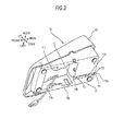
- Fig. 3 is an appearance view of the foot controller 10 of the embodiment disclosed here as viewed from the oblique downward direction.
- a harness through groove 11h that communicates with the first harness through hole 11b, a fourth harness through hole 11i that communicates with the harness through groove 11h, and a harness storage portion 11j that communicates with the fourth harness through hole 11i are formed integrally with the base casing 11 at the back of the base casing 11 of the foot controller 10.
- the harness storage portion 11j is provided with two harness presser guides 11k for preventing the harness 2 from jumping out of the harness storage portion 11j when the harness 2 is rounded into a small ring shape and stored in the harness storage portion 11j when the sewing machine 1 is not used.
- the harness through groove 11h is provided with four harness presser guides 11l for preventing the harness 2 from jumping out of the harness through groove 11h when the harness 2 is inserted therethrough.
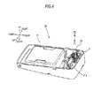
- Fig. 4 is an explanatory view of the foot controller 10 of the embodiment disclosed here.
- a mount 21 is attached to the back of the inside of the base casing 11, and a vertical rack 22 (a first movement member or a first rack) is attached into a vertical rack guide 21a of the mount 21.
- the vertical rack 22 is attached so as to become substantially right-angled to the inner bottom surface of the base casing 11.
- An upper portion of the vertical rack 22 is formed so as to have a circular-arc cross-section.
- Figs. 5A and 5B are structural views of the moving device 20 disclosed here.
- Fig. 5A is a structural view of the overall moving device 20
- Fig. 5B is a structural view of a movement direction changing mechanism portion 26 in the moving device 20.
- the vertical rack 22, a horizontal rack 24 (a second movement member or a second rack), a gear 23 (rotary body), and a variable resistor 25 are attached to the mount 21, and form the moving device 20.
- the vertical rack 22 is attached into the vertical rack guide 21a via a first mount slide groove 22b
- the horizontal rack 24 is attached into a horizontal rack guide 21b via a second mount slide groove 24b
- the gear 23 is attached into a gear guide 21e via a gear turning shaft 23c (not shown)
- the variable resistor 25 is attached below the horizontal rack 24.
- a first rack portion 22c of the vertical rack 22 engages a gear 23a of the gear 23.
- the gear 23a is formed integrally with a pinion 23b to form the gear 23.
- the pinion 23b engages a second rack portion 24a formed integrally with the horizontal rack 24.
- the horizontal rack 24 integrally forms a variable resistor lever operating portion 24c that operates a variable resistor lever 25a of the variable resistor 25 on the lower side thereof.
- a moving device return spring 22e is engaged between the mount 21 and the vertical rack 22.
- the diameter of the gear 23a is made larger than the diameter of the pinion 23b.
- the pushing force of the vertical rack 22 is set small, it is also possible to make the diameter of the gear 23a smaller than the diameter of the pinion 23b for a user who selects to keep the relationship between a stepping amount and sewing speed from being keen. Moreover, it is also possible to meet user's demands by changing the module of the gear 23a and the pinion 23b instead of adjusting the diameter of the gear 23a and the pinion 23b.
- Figs. 6A and 6B are schematic views of the foot controller 10 of the embodiment disclosed here, and a graph of the relationship between stepping amount and load.
- the first rack portion 22c of the vertical rack 22, the gear 23a of the gear 23, the pinion 23b formed integrally with the gear 23, and the second rack portion 24a of the horizontal rack 24 form the mechanism portion 26.
- the vertical rack 22 can perform vertical adjustment movement within a range of a movement amount L1.
- the horizontal rack 24 can perform right and left adjustment movement within a range of a movement amount L2 in synchronization with the adjustment movement by the gear 23a.
- the moving device return spring 22e is compressed and the horizontal rack 24 moves leftward in the drawing. If the user makes the stepping power P to the stepping casing 12 small, the moving device return spring 22e is extended and the horizontal rack 24 moves rightward in the drawing.
- the variable resistor lever operating portion 24c formed integrally with the horizontal rack 24 is engaged with the variable resistor lever 25a of the variable resistor 25, and performs right and left adjustment movement of the variable resistor lever 25a in accordance with the movement of the horizontal rack 24.
- the stepping amount L1 is movable from zero to Lmax.
- the movement amount of the variable resistor lever 25a of the variable resistor 25 can be adjusted from zero to L2 according to the stepping amount L1.
- the relationship between the stepping power P according to the stepping amount L1 and a compressive force F applied to the moving device return spring 22e becomes like the graph of Fig. 6B .
- the sewing machine 1 of the embodiment is configured so that the moving device 20 includes the vertical rack 22 that moves in the stepping direction of the foot controller 10, the gear 23 that converts the movement amount L1 of the vertical rack 22 into a rotational amount, and the horizontal rack 24 that converts the rotational amount of the gear 23 in a direction orthogonal to the movement direction of the vertical rack 22 and moves by L2, and is configured to change the resistance value of the variable resistor 25 when the horizontal rack 24 moves in the direction orthogonal to the movement direction of the vertical rack 22.
- a component force in an oblique direction is not generated among the vertical rack 22, the gear 23, and the horizontal rack 24, and the variable resistor 25 can be operated with a high transmission efficiency.
- a maximum stepping force is required by about 3.57 times a compressive force (the setting value of a spring force) Fmax applied to the moving device return spring 122e (refer to Fig. 9 ).
- the maximum stepping force is merely 0.87 times the compressive force (the setting value of the spring force) Fmax applied to the moving device return spring 22e so that easy operation can be made. This is based on the following three reasons.
- the first reason is that, in the foot controller 10 of the embodiment, meshing portions of a gear that is involved in the process in which the user's stepping power P is converted into the compressive force Fmax applied to the moving device return spring 22e are present in the mechanism portion 26 in only two places between the vertical rack 22 and the gear 23 and between the gear 23 and the horizontal rack 24.
- the second reason is that the conversion efficiency of the meshing portion of each gear is as high as about 98%.
- the third reason is that output is amplified to 1.2 times according to the amplification factor of the mechanism portion 26. (Since the detailed calculation of the stepping force in the foot controller 110 of the background discussion is described in the description of operation of the background discussion, refer to that).
- the stepping load to the user's stepping amount L1 linear like the graph of Fig. 6B .
- the user easily catches the correlation between the stepping amount L1 and the sewing speed linearly, and can operate the sewing machine 1 with a high precision more closely to s natural feeling.
- the mechanism portion 26 of the embodiment can be constituted from resin parts called polyoxymethylene (POM) with high strength and excellent lubricity, the user can be provided with cheap products.
- the foot controller 10 of the embodiment can be manufactured more cheaply than that of the background discussion in which two variable resistors, a changeover switch, and an accessory circuit are built.
- the foot controller 10 of the embodiment can realize functions equivalent to a multifunctional sewing machine having a computer built therein, with a configuration that is easier than that of the background discussion by preparing a plurality of microcomputer control patterns in combination with the multifunctional sewing machine.
- the sewing machine 1 of the embodiment is configured so that the moving device 20 includes the vertical rack 22 that moves in the stepping direction of the foot controller 10, the gear 23 that converts the movement amount L1 of the vertical rack 22 into a rotational amount, the horizontal rack 24 that converts the rotational amount of the gear 23 in the direction orthogonal to the stepping direction of the vertical rack 22 and moves by the movement amount L2, and the variable resistor lever 25a that changes the resistance value of the variable resistor 25 when the horizontal rack 24 moves.
- the transmission efficiency of forces among the vertical rack 22, the gear 23, and the horizontal rack 24 can be further improved, and the variable resistor 25 can be operated with a high transmission efficiency.
- the movement direction of the moving device 20 is changed from the direction orthogonal to the turning shaft 11a of the stepping portion of the foot controller 10 to a parallel direction. This is because the size of the moving device 20 can be reduced as the conversion efficiency of the mechanism portion 26 is improved.
- the harness storage portion 11j it is possible to form the harness storage portion 11j at a position on the turning shaft 11a side in the direction orthogonal to the turning shaft 11a of the stepping portion of the foot controller 10.
- the harness storage portion 11j it is possible to round the harness 2 into, for example, a small ring shape to store the harness to the harness storage portion 11j when the sewing machine 1 is not used, and organizing of the sewing machine 1 can be made easier.
- Fig. 7 is a cross-sectional view of a foot controller 110 of the background discussion.
- the foot controller 110 is provided with a base casing 111 (foundation) that comes into contact with a floor surface 109, a stepping casing 112 (stepping plate) that is turnably born about a base casing turning shaft 111a (fulcrum shaft E) provided at one end of the base casing 111, a variable resistor 125 that is provided inside the foot controller 110 (pedal) formed by the stepping casing 112 and the base casing 111, a front arm 111b (link) that has one end turnably coupled to a mount 121 (link foundation), a rear arm 111c (link) that has one end turnably coupled to the other end of the front arm 111b and the other end coming into a slidable contact with a variable resistor lever 125a of the variable resistor 125, and a moving device return spring 122e (tension spring) that is coupled to one end of the front arm 111b and the other
- a coupling portion between the front arm 111b and the rear arm 111c moves upward as one end of the front arm 111b and the other end of the rear arm 111c are drawn to each other by the moving device return spring 122e, and is brought into pressure contact with the rear surface of the stepping casing 112 via a roller 111d turnably provided at the coupling portion.
- a second moving device return spring 122f that biases the stepping casing 112 so as to be kept away from the base casing 111 on the base casing turning shaft 111a is provided inside the foot controller 110, and the stepping casing 112 and the base casing 111 are locked to each other by convex portions provided at tips thereof, respectively, so as to approach and separate from each other within a predetermined range.
- the stepping casing 112 is stepped on by a user, the other end of the rear arm 111c moves, and the resistance value that determines the rotational frequency of the sewing machine motor 6 changes by the variable resistor 125 so that the sewing speed can be controlled.
- Figs. 8A and 8B are explanatory views of the force relationship of the foot controller of the background discussion.
- Fig. 8A is an explanatory view of the stepping force and load of the foot controller and
- Fig. 8B is a graph of the relationship between the stepping amount and load of the foot controller.
- Fig, 9 is an explanatory view for the calculation based on a schematic view of the foot controller of the background discussion. If a user steps on the stepping casing 112 and applies stepping power P to the coupling portion between the front arm 111b and the rear arm 111c, the rear arm 111c is pushed out backward by a movement amount L4 against the resultant force F of the moving device return spring 122e and the second moving device return spring 122f.
- the stepping amount L3 is movable from zero to Lmax.
- the movement amount of the variable resistor lever 125a of the variable resistor 125 can be adjusted from zero to L4 according to the stepping amount L3. If the user makes the stepping power P to the stepping casing 112 large, the moving device return spring 122e and the second moving device return spring 122f are compressed and the variable resistor lever 125a moves leftward in the drawing. If the stepping power P to the stepping casing 112 is made small, the moving device return spring 122e and the second moving device return spring 122f are extended by the resultant force of the moving device return spring 122e and the second moving device return spring 122f, and the variable resistor lever 125a moves rightward in the drawing.
- the relationship among the stepping power P, the resultant force F, and the stepping amount L3 in this case becomes like the graph of Fig. 8B . That is, in the foot controller 10 of the background discussion, the maximum stepping force is required to be about 3.57 times the resultant force (the setting value of a spring force) Fmax of the moving device return spring 122e and the second moving device return spring 122f. If the frictional resistance force of the sliding portion is included in this calculation value, it is expected that a force of 4 times or more the force of the embodiment is required. Additionally, the stepping load to the user's stepping amount L3 increases abruptly from a certain point like the graph.
Landscapes
- Engineering & Computer Science (AREA)
- Mechanical Engineering (AREA)
- Textile Engineering (AREA)
- Sewing Machines And Sewing (AREA)
Applications Claiming Priority (1)
| Application Number | Priority Date | Filing Date | Title |
|---|---|---|---|
| JP2012065520A JP5966484B2 (ja) | 2012-03-22 | 2012-03-22 | ミシン |
Publications (2)
| Publication Number | Publication Date |
|---|---|
| EP2642010A1 true EP2642010A1 (de) | 2013-09-25 |
| EP2642010B1 EP2642010B1 (de) | 2016-11-30 |
Family
ID=47913240
Family Applications (1)
| Application Number | Title | Priority Date | Filing Date |
|---|---|---|---|
| EP13160689.9A Not-in-force EP2642010B1 (de) | 2012-03-22 | 2013-03-22 | Nähmaschine |
Country Status (3)
| Country | Link |
|---|---|
| EP (1) | EP2642010B1 (de) |
| JP (1) | JP5966484B2 (de) |
| CN (1) | CN203200495U (de) |
Families Citing this family (1)
| Publication number | Priority date | Publication date | Assignee | Title |
|---|---|---|---|---|
| CN105926178B (zh) * | 2016-06-29 | 2019-01-22 | 广东溢达纺织有限公司 | 车缝系统及车缝方法 |
Citations (5)
| Publication number | Priority date | Publication date | Assignee | Title |
|---|---|---|---|---|
| GB403881A (en) * | 1933-05-30 | 1934-01-04 | Singer Mfg Co | Foot-operated motor-controller |
| JPS54144247A (en) * | 1978-04-28 | 1979-11-10 | Brother Ind Ltd | Foottoperated controller |
| JPS554472U (de) | 1978-06-26 | 1980-01-12 | ||
| EP0053938A1 (de) * | 1980-12-09 | 1982-06-16 | Matsushita Electric Industrial Co., Ltd. | Vorrichtung zum Regeln der Antriebsgeschwindigkeit bei einer Nähmaschine |
| JP2008245728A (ja) | 2007-03-29 | 2008-10-16 | Juki Corp | ミシンの足踏みペダル |
Family Cites Families (1)
| Publication number | Priority date | Publication date | Assignee | Title |
|---|---|---|---|---|
| JPS54168946U (de) * | 1978-05-19 | 1979-11-29 |
-
2012
- 2012-03-22 JP JP2012065520A patent/JP5966484B2/ja not_active Expired - Fee Related
-
2013
- 2013-03-22 CN CN 201320135550 patent/CN203200495U/zh not_active Expired - Lifetime
- 2013-03-22 EP EP13160689.9A patent/EP2642010B1/de not_active Not-in-force
Patent Citations (5)
| Publication number | Priority date | Publication date | Assignee | Title |
|---|---|---|---|---|
| GB403881A (en) * | 1933-05-30 | 1934-01-04 | Singer Mfg Co | Foot-operated motor-controller |
| JPS54144247A (en) * | 1978-04-28 | 1979-11-10 | Brother Ind Ltd | Foottoperated controller |
| JPS554472U (de) | 1978-06-26 | 1980-01-12 | ||
| EP0053938A1 (de) * | 1980-12-09 | 1982-06-16 | Matsushita Electric Industrial Co., Ltd. | Vorrichtung zum Regeln der Antriebsgeschwindigkeit bei einer Nähmaschine |
| JP2008245728A (ja) | 2007-03-29 | 2008-10-16 | Juki Corp | ミシンの足踏みペダル |
Also Published As
| Publication number | Publication date |
|---|---|
| CN203200495U (zh) | 2013-09-18 |
| JP2013192863A (ja) | 2013-09-30 |
| EP2642010B1 (de) | 2016-11-30 |
| JP5966484B2 (ja) | 2016-08-10 |
Similar Documents
| Publication | Publication Date | Title |
|---|---|---|
| US8359947B2 (en) | Resistance mechanism for a pedal assembly | |
| JP2009119048A (ja) | 片針切り替え装置 | |
| EP3199017B1 (de) | Griff für elektrowerkzeuge und elektrowerkzeug damit | |
| US9513656B2 (en) | Vehicle pedal resistance and kickdown assembly | |
| US20140165411A1 (en) | Electric Shears | |
| JP2006505441A (ja) | 自動車のオートマチックトランスミッションにシフト指令を伝達するためのシフト装置 | |
| EP2642010B1 (de) | Nähmaschine | |
| CN101752130B (zh) | 带固定接点壳体及具备该壳体的滑动开关 | |
| US10626536B2 (en) | Foot-operated controller of sewing machine | |
| US8402903B2 (en) | Feed dog device for a sewing machine | |
| CN111031857A (zh) | 用于使家具或家用电器的可移动部件回缩到端部位置中的回缩装置 | |
| CN109629125B (zh) | 基于包缝机的压脚压力与牙架倾角同步调节方法 | |
| JPWO2014024280A1 (ja) | ベルトアジャスタ | |
| JP2010195398A (ja) | シフトレバー | |
| JPH07117991A (ja) | 可変速形電動巻上機 | |
| JP5751446B2 (ja) | ミシンコントローラおよびミシン | |
| KR20180097601A (ko) | 조작 레버 | |
| US8161897B2 (en) | Knee lever for sewing machine | |
| US20180163331A1 (en) | Foot controller of sewing machine | |
| EP2784204B1 (de) | Knopflochnähmaschine | |
| US7073454B2 (en) | Sewing machine | |
| CN220331216U (zh) | 电动工具 | |
| US10457247B2 (en) | Seat belt buckle presenter | |
| CN105624938A (zh) | 用于缝纫机的驱动组件和包括这种驱动组件的缝纫机 | |
| CN223690298U (zh) | 一种同步信号反馈的换挡操纵机构 |
Legal Events
| Date | Code | Title | Description |
|---|---|---|---|
| PUAI | Public reference made under article 153(3) epc to a published international application that has entered the european phase |
Free format text: ORIGINAL CODE: 0009012 |
|
| AK | Designated contracting states |
Kind code of ref document: A1 Designated state(s): AL AT BE BG CH CY CZ DE DK EE ES FI FR GB GR HR HU IE IS IT LI LT LU LV MC MK MT NL NO PL PT RO RS SE SI SK SM TR |
|
| AX | Request for extension of the european patent |
Extension state: BA ME |
|
| 17P | Request for examination filed |
Effective date: 20140325 |
|
| RBV | Designated contracting states (corrected) |
Designated state(s): AL AT BE BG CH CY CZ DE DK EE ES FI FR GB GR HR HU IE IS IT LI LT LU LV MC MK MT NL NO PL PT RO RS SE SI SK SM TR |
|
| 17Q | First examination report despatched |
Effective date: 20141001 |
|
| GRAP | Despatch of communication of intention to grant a patent |
Free format text: ORIGINAL CODE: EPIDOSNIGR1 |
|
| INTG | Intention to grant announced |
Effective date: 20160212 |
|
| GRAS | Grant fee paid |
Free format text: ORIGINAL CODE: EPIDOSNIGR3 |
|
| GRAP | Despatch of communication of intention to grant a patent |
Free format text: ORIGINAL CODE: EPIDOSNIGR1 |
|
| INTG | Intention to grant announced |
Effective date: 20160627 |
|
| GRAA | (expected) grant |
Free format text: ORIGINAL CODE: 0009210 |
|
| AK | Designated contracting states |
Kind code of ref document: B1 Designated state(s): AL AT BE BG CH CY CZ DE DK EE ES FI FR GB GR HR HU IE IS IT LI LT LU LV MC MK MT NL NO PL PT RO RS SE SI SK SM TR |
|
| REG | Reference to a national code |
Ref country code: CH Ref legal event code: EP Ref country code: GB Ref legal event code: FG4D |
|
| REG | Reference to a national code |
Ref country code: AT Ref legal event code: REF Ref document number: 849901 Country of ref document: AT Kind code of ref document: T Effective date: 20161215 |
|
| REG | Reference to a national code |
Ref country code: IE Ref legal event code: FG4D |
|
| REG | Reference to a national code |
Ref country code: DE Ref legal event code: R096 Ref document number: 602013014603 Country of ref document: DE |
|
| REG | Reference to a national code |
Ref country code: FR Ref legal event code: PLFP Year of fee payment: 5 |
|
| PG25 | Lapsed in a contracting state [announced via postgrant information from national office to epo] |
Ref country code: LV Free format text: LAPSE BECAUSE OF FAILURE TO SUBMIT A TRANSLATION OF THE DESCRIPTION OR TO PAY THE FEE WITHIN THE PRESCRIBED TIME-LIMIT Effective date: 20161130 |
|
| REG | Reference to a national code |
Ref country code: LT Ref legal event code: MG4D |
|
| REG | Reference to a national code |
Ref country code: NL Ref legal event code: MP Effective date: 20161130 |
|
| REG | Reference to a national code |
Ref country code: AT Ref legal event code: MK05 Ref document number: 849901 Country of ref document: AT Kind code of ref document: T Effective date: 20161130 |
|
| PG25 | Lapsed in a contracting state [announced via postgrant information from national office to epo] |
Ref country code: NO Free format text: LAPSE BECAUSE OF FAILURE TO SUBMIT A TRANSLATION OF THE DESCRIPTION OR TO PAY THE FEE WITHIN THE PRESCRIBED TIME-LIMIT Effective date: 20170228 Ref country code: LT Free format text: LAPSE BECAUSE OF FAILURE TO SUBMIT A TRANSLATION OF THE DESCRIPTION OR TO PAY THE FEE WITHIN THE PRESCRIBED TIME-LIMIT Effective date: 20161130 Ref country code: GR Free format text: LAPSE BECAUSE OF FAILURE TO SUBMIT A TRANSLATION OF THE DESCRIPTION OR TO PAY THE FEE WITHIN THE PRESCRIBED TIME-LIMIT Effective date: 20170301 Ref country code: SE Free format text: LAPSE BECAUSE OF FAILURE TO SUBMIT A TRANSLATION OF THE DESCRIPTION OR TO PAY THE FEE WITHIN THE PRESCRIBED TIME-LIMIT Effective date: 20161130 |
|
| PG25 | Lapsed in a contracting state [announced via postgrant information from national office to epo] |
Ref country code: FI Free format text: LAPSE BECAUSE OF FAILURE TO SUBMIT A TRANSLATION OF THE DESCRIPTION OR TO PAY THE FEE WITHIN THE PRESCRIBED TIME-LIMIT Effective date: 20161130 Ref country code: AT Free format text: LAPSE BECAUSE OF FAILURE TO SUBMIT A TRANSLATION OF THE DESCRIPTION OR TO PAY THE FEE WITHIN THE PRESCRIBED TIME-LIMIT Effective date: 20161130 Ref country code: PT Free format text: LAPSE BECAUSE OF FAILURE TO SUBMIT A TRANSLATION OF THE DESCRIPTION OR TO PAY THE FEE WITHIN THE PRESCRIBED TIME-LIMIT Effective date: 20170330 Ref country code: PL Free format text: LAPSE BECAUSE OF FAILURE TO SUBMIT A TRANSLATION OF THE DESCRIPTION OR TO PAY THE FEE WITHIN THE PRESCRIBED TIME-LIMIT Effective date: 20161130 Ref country code: RS Free format text: LAPSE BECAUSE OF FAILURE TO SUBMIT A TRANSLATION OF THE DESCRIPTION OR TO PAY THE FEE WITHIN THE PRESCRIBED TIME-LIMIT Effective date: 20161130 Ref country code: ES Free format text: LAPSE BECAUSE OF FAILURE TO SUBMIT A TRANSLATION OF THE DESCRIPTION OR TO PAY THE FEE WITHIN THE PRESCRIBED TIME-LIMIT Effective date: 20161130 Ref country code: HR Free format text: LAPSE BECAUSE OF FAILURE TO SUBMIT A TRANSLATION OF THE DESCRIPTION OR TO PAY THE FEE WITHIN THE PRESCRIBED TIME-LIMIT Effective date: 20161130 |
|
| PG25 | Lapsed in a contracting state [announced via postgrant information from national office to epo] |
Ref country code: NL Free format text: LAPSE BECAUSE OF FAILURE TO SUBMIT A TRANSLATION OF THE DESCRIPTION OR TO PAY THE FEE WITHIN THE PRESCRIBED TIME-LIMIT Effective date: 20161130 |
|
| PG25 | Lapsed in a contracting state [announced via postgrant information from national office to epo] |
Ref country code: DK Free format text: LAPSE BECAUSE OF FAILURE TO SUBMIT A TRANSLATION OF THE DESCRIPTION OR TO PAY THE FEE WITHIN THE PRESCRIBED TIME-LIMIT Effective date: 20161130 Ref country code: RO Free format text: LAPSE BECAUSE OF FAILURE TO SUBMIT A TRANSLATION OF THE DESCRIPTION OR TO PAY THE FEE WITHIN THE PRESCRIBED TIME-LIMIT Effective date: 20161130 Ref country code: EE Free format text: LAPSE BECAUSE OF FAILURE TO SUBMIT A TRANSLATION OF THE DESCRIPTION OR TO PAY THE FEE WITHIN THE PRESCRIBED TIME-LIMIT Effective date: 20161130 Ref country code: SK Free format text: LAPSE BECAUSE OF FAILURE TO SUBMIT A TRANSLATION OF THE DESCRIPTION OR TO PAY THE FEE WITHIN THE PRESCRIBED TIME-LIMIT Effective date: 20161130 Ref country code: CZ Free format text: LAPSE BECAUSE OF FAILURE TO SUBMIT A TRANSLATION OF THE DESCRIPTION OR TO PAY THE FEE WITHIN THE PRESCRIBED TIME-LIMIT Effective date: 20161130 |
|
| PG25 | Lapsed in a contracting state [announced via postgrant information from national office to epo] |
Ref country code: BE Free format text: LAPSE BECAUSE OF FAILURE TO SUBMIT A TRANSLATION OF THE DESCRIPTION OR TO PAY THE FEE WITHIN THE PRESCRIBED TIME-LIMIT Effective date: 20161130 Ref country code: IT Free format text: LAPSE BECAUSE OF FAILURE TO SUBMIT A TRANSLATION OF THE DESCRIPTION OR TO PAY THE FEE WITHIN THE PRESCRIBED TIME-LIMIT Effective date: 20161130 Ref country code: SM Free format text: LAPSE BECAUSE OF FAILURE TO SUBMIT A TRANSLATION OF THE DESCRIPTION OR TO PAY THE FEE WITHIN THE PRESCRIBED TIME-LIMIT Effective date: 20161130 Ref country code: BG Free format text: LAPSE BECAUSE OF FAILURE TO SUBMIT A TRANSLATION OF THE DESCRIPTION OR TO PAY THE FEE WITHIN THE PRESCRIBED TIME-LIMIT Effective date: 20170228 |
|
| REG | Reference to a national code |
Ref country code: DE Ref legal event code: R097 Ref document number: 602013014603 Country of ref document: DE |
|
| PLBE | No opposition filed within time limit |
Free format text: ORIGINAL CODE: 0009261 |
|
| STAA | Information on the status of an ep patent application or granted ep patent |
Free format text: STATUS: NO OPPOSITION FILED WITHIN TIME LIMIT |
|
| REG | Reference to a national code |
Ref country code: CH Ref legal event code: PL |
|
| 26N | No opposition filed |
Effective date: 20170831 |
|
| GBPC | Gb: european patent ceased through non-payment of renewal fee |
Effective date: 20170322 |
|
| PG25 | Lapsed in a contracting state [announced via postgrant information from national office to epo] |
Ref country code: SI Free format text: LAPSE BECAUSE OF FAILURE TO SUBMIT A TRANSLATION OF THE DESCRIPTION OR TO PAY THE FEE WITHIN THE PRESCRIBED TIME-LIMIT Effective date: 20161130 Ref country code: MC Free format text: LAPSE BECAUSE OF FAILURE TO SUBMIT A TRANSLATION OF THE DESCRIPTION OR TO PAY THE FEE WITHIN THE PRESCRIBED TIME-LIMIT Effective date: 20161130 |
|
| REG | Reference to a national code |
Ref country code: IE Ref legal event code: MM4A |
|
| PG25 | Lapsed in a contracting state [announced via postgrant information from national office to epo] |
Ref country code: LU Free format text: LAPSE BECAUSE OF NON-PAYMENT OF DUE FEES Effective date: 20170322 |
|
| REG | Reference to a national code |
Ref country code: FR Ref legal event code: PLFP Year of fee payment: 6 |
|
| PG25 | Lapsed in a contracting state [announced via postgrant information from national office to epo] |
Ref country code: LI Free format text: LAPSE BECAUSE OF NON-PAYMENT OF DUE FEES Effective date: 20170331 Ref country code: IE Free format text: LAPSE BECAUSE OF NON-PAYMENT OF DUE FEES Effective date: 20170322 Ref country code: CH Free format text: LAPSE BECAUSE OF NON-PAYMENT OF DUE FEES Effective date: 20170331 Ref country code: GB Free format text: LAPSE BECAUSE OF NON-PAYMENT OF DUE FEES Effective date: 20170322 |
|
| PG25 | Lapsed in a contracting state [announced via postgrant information from national office to epo] |
Ref country code: MT Free format text: LAPSE BECAUSE OF NON-PAYMENT OF DUE FEES Effective date: 20170322 |
|
| PG25 | Lapsed in a contracting state [announced via postgrant information from national office to epo] |
Ref country code: HU Free format text: LAPSE BECAUSE OF FAILURE TO SUBMIT A TRANSLATION OF THE DESCRIPTION OR TO PAY THE FEE WITHIN THE PRESCRIBED TIME-LIMIT; INVALID AB INITIO Effective date: 20130322 |
|
| PG25 | Lapsed in a contracting state [announced via postgrant information from national office to epo] |
Ref country code: CY Free format text: LAPSE BECAUSE OF NON-PAYMENT OF DUE FEES Effective date: 20161130 |
|
| PG25 | Lapsed in a contracting state [announced via postgrant information from national office to epo] |
Ref country code: MK Free format text: LAPSE BECAUSE OF FAILURE TO SUBMIT A TRANSLATION OF THE DESCRIPTION OR TO PAY THE FEE WITHIN THE PRESCRIBED TIME-LIMIT Effective date: 20161130 |
|
| REG | Reference to a national code |
Ref country code: DE Ref legal event code: R082 Ref document number: 602013014603 Country of ref document: DE Representative=s name: TBK, DE Ref country code: DE Ref legal event code: R081 Ref document number: 602013014603 Country of ref document: DE Owner name: JAGUAR INTERNATIONAL CORPORATION, MORIGUCHI-SH, JP Free format text: FORMER OWNER: AISIN SEIKI KABUSHIKI KAISHA, KARIYA-SHI, AICHI, JP |
|
| PG25 | Lapsed in a contracting state [announced via postgrant information from national office to epo] |
Ref country code: TR Free format text: LAPSE BECAUSE OF FAILURE TO SUBMIT A TRANSLATION OF THE DESCRIPTION OR TO PAY THE FEE WITHIN THE PRESCRIBED TIME-LIMIT Effective date: 20161130 |
|
| PG25 | Lapsed in a contracting state [announced via postgrant information from national office to epo] |
Ref country code: AL Free format text: LAPSE BECAUSE OF FAILURE TO SUBMIT A TRANSLATION OF THE DESCRIPTION OR TO PAY THE FEE WITHIN THE PRESCRIBED TIME-LIMIT Effective date: 20161130 Ref country code: IS Free format text: LAPSE BECAUSE OF FAILURE TO SUBMIT A TRANSLATION OF THE DESCRIPTION OR TO PAY THE FEE WITHIN THE PRESCRIBED TIME-LIMIT Effective date: 20170330 |
|
| PGFP | Annual fee paid to national office [announced via postgrant information from national office to epo] |
Ref country code: DE Payment date: 20220203 Year of fee payment: 10 |
|
| PGFP | Annual fee paid to national office [announced via postgrant information from national office to epo] |
Ref country code: FR Payment date: 20220209 Year of fee payment: 10 |
|
| REG | Reference to a national code |
Ref country code: DE Ref legal event code: R119 Ref document number: 602013014603 Country of ref document: DE |
|
| PG25 | Lapsed in a contracting state [announced via postgrant information from national office to epo] |
Ref country code: FR Free format text: LAPSE BECAUSE OF NON-PAYMENT OF DUE FEES Effective date: 20230331 Ref country code: DE Free format text: LAPSE BECAUSE OF NON-PAYMENT OF DUE FEES Effective date: 20231003 |