EP2642052A2 - Treibriegel-Schaltschloss - Google Patents
Treibriegel-Schaltschloss Download PDFInfo
- Publication number
- EP2642052A2 EP2642052A2 EP13155871.0A EP13155871A EP2642052A2 EP 2642052 A2 EP2642052 A2 EP 2642052A2 EP 13155871 A EP13155871 A EP 13155871A EP 2642052 A2 EP2642052 A2 EP 2642052A2
- Authority
- EP
- European Patent Office
- Prior art keywords
- bolt
- lock
- drive
- latch
- espagnolette
- Prior art date
- Legal status (The legal status is an assumption and is not a legal conclusion. Google has not performed a legal analysis and makes no representation as to the accuracy of the status listed.)
- Granted
Links
Images
Classifications
-
- E—FIXED CONSTRUCTIONS
- E05—LOCKS; KEYS; WINDOW OR DOOR FITTINGS; SAFES
- E05C—BOLTS OR FASTENING DEVICES FOR WINGS, SPECIALLY FOR DOORS OR WINDOWS
- E05C7/00—Fastening devices specially adapted for two wings
- E05C7/04—Fastening devices specially adapted for two wings for wings which abut when closed
- E05C7/045—Sliding bolts mounted on or in the edge of a normally closed wing of a double-door or -window
-
- E—FIXED CONSTRUCTIONS
- E05—LOCKS; KEYS; WINDOW OR DOOR FITTINGS; SAFES
- E05B—LOCKS; ACCESSORIES THEREFOR; HANDCUFFS
- E05B63/00—Locks or fastenings with special structural characteristics
- E05B63/18—Locks or fastenings with special structural characteristics with arrangements independent of the locking mechanism for retaining the bolt or latch in the retracted position
- E05B63/20—Locks or fastenings with special structural characteristics with arrangements independent of the locking mechanism for retaining the bolt or latch in the retracted position released automatically when the wing is closed
-
- E—FIXED CONSTRUCTIONS
- E05—LOCKS; KEYS; WINDOW OR DOOR FITTINGS; SAFES
- E05C—BOLTS OR FASTENING DEVICES FOR WINGS, SPECIALLY FOR DOORS OR WINDOWS
- E05C9/00—Arrangements of simultaneously actuated bolts or other securing devices at well-separated positions on the same wing
- E05C9/18—Details of fastening means or of fixed retaining means for the ends of bars
- E05C9/1825—Fastening means
- E05C9/1833—Fastening means performing sliding movements
- E05C9/185—Fastening means performing sliding movements parallel with actuating bar
Definitions
- the invention relates to a drive bolt lock mechanism according to the preamble of claim 1.
- a lock has become known with an auxiliary trap, the latch is released when pressed back auxiliary latch.
- the inclined to the latch and limited pivotally mounted auxiliary latch on a locking arm which is attributable to a locking recess of the bolt. If the auxiliary latch is inserted against a return spring, it pivots out of the locking recess with the locking arm and the spring-loaded latch closes.
- the invention is therefore based on the object to enable a safe and reliable release of the drive bolt with minimal space.
- the release means consists of a displaceable in the direction of movement of the drive bolt on the lock plate protruding button, which is associated with the blocking element on a plane inclined to the direction of displacement first surface.
- Locking element and buttons are therefore independent components that can be arranged spatially spaced from each other. The funds used are easy to procure and easy to manufacture and cause the required movement with a small size.
- a further embodiment provides that the button has a pointed wedge shape and passes through a hole in the lock plate with its roof-shaped end. This embodiment allows a symmetrical configuration of the probe, so that the drive bolt latch can be used for right and left pivoting wings.
- the lock housing and / or the lockthruster consists of a substantially U-shaped profile section, in which a base plate guiding the blocking element is received.
- the drive rod of the espagnolette lock is associated with a coupling member for connection to the latch. This also ensures that the adaptation of the bolt can take place in or near the upper edge of the wing.
- a simple embodiment which also allows easy adjustability of the bolt, provides that the coupling member has a threaded bore for coupling with a cylindrical rod of the locking member.
- the rod of the locking member is associated with a flat rectangular latch, then in connection with a shape adapted to the bolt passage opening in the drive bolt latch lock anti-rotation is achieved.
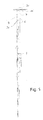
- FIG. 1 is in the schematic representation of an attached to a passive leaf of a two-leaf door espagnolette with 4 designated can be operated in a known manner via a pusher, not shown here.
- the inactive leaf can be fixed to the frame even when the active leaf is open via espagnolette lock 4 and the latching component 6, which is coupled thereto in terms of movement, and its latch 7.
- the latch 7 engages in a closing opening of a frame-side locking engagement 30, which in turn carries a projecting in the direction of the inactive cam.
- the locking member 6 is coupled via a drive rod 9 with the espagnolette lock 4 and is with this drive-connected.
- the drive rod 9 and thereby also the rigid drive-connected latch 7 are spring-loaded as a result of the design of the espagnolette lock 4 in the closing direction.
- the drive rod 9 is associated with a coupling member 31 which transmits the movement of the drive rod 9 in an offset plane.
- the coupling member 31 protrudes from the back of the drive rod 9 and the locking member 6 couples thereto in a recording.
- the coupling member has a threaded bore 7a for coupling with a cylindrical rod 7b of the locking member.
- the rod 7b may be formed as a threaded rod.
- the cylindrical rod of the locking member is associated with the flat rectangular or a flattened at opposite longitudinal edges bar 7.
- the bolt 7 and the rod 7b are coupled via a threaded connection.
- the coupling member may also be arranged in the secondary lock box.
- the latch 7 does not precede in its locked position with open wing, which would lead to the damage when closing the passive leaf, this can be fixed in its deactivated, ie retracted position.
- the latch component 6 is assigned a drive bolt latching mechanism 10.
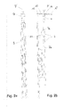
- the floating bolt lock 10 is assigned to the locking component 6 on the upper edge remote from the rotary axis. However, it may also be attached to the opposite lower wing edge, if necessary, in addition. It is in the Fig. 2b recognizable that the drive bolt latch 10 has a substantially flat rectangular lock housing 12 and that a lock plate 13 forms an upper housing closure. About this lock plate 13 projects a trigger means 14 before. It is also a located on the back of the bolt 7 recess 7 'recognizable. This recess 7 'forms horizontally extending blocking edges.
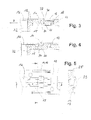
- FIGS. 3 and 4 is in longitudinal section respectively the deactivated position of a blocking element 15 (FIG. Fig. 3 ) and its activated position ( Fig. 4 ).
- the cross-sectional flat rectangular latch 7 is, as already stated above, drive-coupled via the coupling member 31 to the drive rod 9 of the espagnolette lock 4.
- the drive rod 9 and thereby also the bolt 7 of the locking member 6 are spring-loaded and in the in the Fig. 2a, 2b shown locked position urged.
- the bolt 7 passes through a passage opening 16 of the lock plate 13 and the lock housing 12, wherein in the illustrated embodiment, a guide extension 32 is provided on the lock housing 12 on the underside.
- the activated locking element 15 protrudes into the passage opening 16 of the bolt 7 and is mounted displaceably in the lock housing 12 substantially transversely to the direction of movement of the bolt 7.
- the passage opening 16 is adapted with play to the cross-sectional shape of the bolt 7.
- the latch 7 is mounted against rotation on the drive bolt latching mechanism.
- the blocking element 15 is subjected to force by means of a designated 18 and designed as a compression spring force storage device in its activated position.
- the locking element 15 is associated with the release means 14, which consists of a displaceable in the direction of movement of the bolt 7 on the lock plate 13 protruding button 19 which is associated with the blocking element 15 at an inclined to the direction of displacement R extending first surface 20.
- the button 19 has a pointed wedge shape, the roof-shaped end 33 of the Schlossstulps 13 tapered conically over and this passes through in an opening.
- the button 19 is located on the inclined first surface 20 at.
- the inclined surface 20 is pulled down to a horizontal web 34 in the illustrated embodiment.
- the button 19 is in its depressed position. Due to this arrangement, the button 19 is movably mounted between the surface 20, and the web 34 and is due to the Federkraftbeetzschung of the blocking element 15 and in the in Fig. 4 situation urged.
- the roof shape of the button 19 and its means of symmetrical mounting in the lock housing 12 allow use of the drive bolt latch 10 on the right and left wings.
- the inclined surfaces 20, 35 in conjunction with the roof shape of the probe 19 also lead to a despite the low mobility of the push button 19 large stroke of the locking element 15.
- This allows a pinpoint sensitive retraction of the locking element 15 at a minimum height, which is also ensured in that the latch 7 is not released until the frame-side latch inlet opening and the passage opening 16 lie opposite one another. Due to the fact that the blocking element 15 is always subjected to spring force, adjustment or adjustment work is unnecessary because of the relative position of the blocking element 15 relative to the latch 7.
- the lock housing 12 consists of a substantially U-shaped base plate 25 in which is guided in the locking element 15 and on which also the compression spring 18 is supported.
- the base plate 25 and the lock plate 13 are firmly connected.
- the blocking element 15 can also cooperate with the dull end of the bolt 7, so that it requires no special embodiment of the bolt 7 or locking edges.
- the blocking element is essentially Z-shaped, so that a stop cooperating with a projection of the base plate 25 results, which limits the blocking element 15 in the unassembled state in its pre-emergence.
- the lock housing 12 is designed angular for ease of assembly and thereby engages the wing edge zwekelnkelig, which facilitates the location assignment to the espagnolette lock 4 and the frame-side locking engagement 30.
Landscapes
- Engineering & Computer Science (AREA)
- Mechanical Engineering (AREA)
- Structural Engineering (AREA)
- Lock And Its Accessories (AREA)
Abstract
Description
- Die Erfindung betrifft ein Treibriegel-Schaltschloss nach dem Oberbegriff des Anspruchs 1.
- Gattungsgemäße Treibriegel-Schaltschlösser sind bereits bekannt. Bei dem aus der
EP 0859106 B1 bekannten Treibriegel-Schaltschloss hat der Schlossstulp eine Bohrung, welche eine Durchtrittsöffnung für einen in Richtung seiner ausgefahrenen Verriegelungsstellung federbelasteten Treibriegel bildet. Es ist an dem Schlossgehäuse ferner eine federbelastete Klemmplatte vorgesehen, die den Treibriegel mit einem Klemmauge umgreift und ihn in beliebigen Einfahrstellungen zu blockieren erlaubt. Vorgesehen ist auch eine den Schlossstulp gleichfalls durchdringende und unter Federkraft stehende Schaltfalle, die bei Auftreffen auf den Türrahmen einzudrücken ist und dabei die Klemmplatte in ihre den Treibriegel freigebende Freigabestellung verschwenkt. - Treibriegel-Schaltschlösser obiger Art sind auch durch die
DE-PS 2746049 DE-PS 2912881 DE-GM 8701630 EP 0635611 B1 und derEP 1201853 B1 . - Bei dem aus der
EP 0859106 B1 bekannten Treibriegel-Schaltschloss ist der zylindrische Treibriegel in einer Klemmhülse aufgenommen, welche ihrerseits in einer sich am Innendurchmesser konisch verjüngenden Hülse aufgenommen ist. Die äußere Hülse lässt sich über einen Taster relativ zur Klemmhülse verlagern, so dass der Treibriegel freigegeben wird, wenn der Taster durch Anlage an dem Rahmen betätigt wird. - Aus der
DE-PS 75175 - Der Erfindung liegt daher die Aufgabe zugrunde, eine sichere und zuverlässige Auslösung des Treibriegels bei minimalem Bauraum zu ermöglichen.
- Zur Lösung dieser Aufgabe sieht die Erfindung vor, dass das Auslösemittel aus einem in Bewegungsrichtung des Treibriegels verlagerbaren über den Schlossstulp vorstehenden Taster besteht, welcher dem Sperrelement an einer geneigt zu dessen Verschieberichtung verlaufenden erste Fläche zugeordnet ist. Sperrelement und Taster sind daher unabhängige Bauteile, die räumlich beabstandet zueinander angeordnet werden können. Dabei sind die verwendeten Mittel einfach beschaffen und leicht herstellbar und bewirken bei geringer Baugröße den erforderlichen Bewegungsweg.
- Eine Weiterbildung sieht vor, dass der Taster eine Spitzkeilform hat und mit seinem dachförmigen Ende eine Bohrung des Schlossstulps durchsetzt. Diese Ausgestaltung erlaubt eine symmetrische Ausgestaltung des Tasters, so dass das Treibriegel-Schaltschloss für nach rechts und nach links schwenkende Flügel verwendet werden kann.
- Vorteilhaft ist es auch, wenn der Taster an der geneigten ersten Fläche mit einer fasenartigen zweiten Fläche anliegt, da diese Anordnung eine leichgängige Beweglichkeit des Tasters sicherstellt.
- Zur Vereinfachung der Herstellung des Treibriegel-Schaltschlosses ist vorgesehen, dass das Schlossgehäuse und/oder der Schlossstulp aus einem im Wesentlichen U-förmigen Profilabschnitt besteht, in dem ein das Sperrelement führende Basisplatte aufgenommen ist.
- Um eine versetzte Anordnung des Riegels bezogen auf das Treibstangenschloss zu erreichen, ist vorgesehen, dass der Treibstange des Treibstangenschlosses ein Kopplungsglied zur Verbindung mit dem Riegel zugeordnet ist. Dadurch wird auch erreicht, dass die Anpassung des Riegels in oder nahe der oberen Flügelkante erfolgen kann.
- Eine einfache Ausgestaltung, die zudem eine leichte Justierbarkeit des Riegels ermöglicht, sieht vor, dass das Kopplungsglied eine Gewindebohrung zur Kopplung mit einer zylindrischen Stange des Riegelbauteils hat.
- Wenn der Stange des Riegelbauteils ein flachrechteckiger Riegel zugeordnet ist, dann ist in Verbindung mit einer zur Formgebung des Riegels angepassten Durchtrittsöffnung im Treibriegel-Schaltschloss eine Verdrehsicherung erreicht.
- Weitere vorteilhafte Ausgestaltungen ergeben sich aus den Zeichnungen. Es zeigt:
- Fig. 1
- eine schematische Übersicht der drehachsenfernen Beschlagteile eines Standflügels einer zweiflügeligen Tür mit einem Treibriegel-Schaltschloss,
- Fig. 2a
- das Treibriegel-Schaltschloss und ein diesem zugeordneten Treibstangenbeschlag in einer Rückansicht,
- Fig. 2b
- das Treibriegel-Schaltschloss nach
Fig. 2a in einer Seitenansicht, - Fig. 3
- einen Längsschnitt entlang der Linie A-A in der
Fig. 5 mit deaktiviertem Sperrglied, - Fig. 4
- einen Längsschnitt entlang der Linie A-A in der
Fig. 5 mit aktiviertem Sperrglied, und - Fig. 5
- eine Draufsicht und ein Querschnitt des Treibriegel-Schaltschlosses unter Verzicht der Schlossstulp-Darstellung.
- In der
Fig. 1 ist in der schematischen Darstellung ein an einem Standflügel einer zweiflügeligen Tür angebrachtes Treibstangenschloss mit 4 bezeichnet kann in bekannter Weise über einen hier nicht dargestellten Drücker betätigt werden. - Der Standflügel ist auch bei geöffnetem Gangflügel über Treibstangenschloss 4 und das daran bewegungsgekoppelte Riegelbauteil 6 und dessen Riegel 7 an dem Rahmen festlegbar. Der Riegel 7 greift in eine Schließöffnung eines rahmenseitigen Riegeleingriffs 30 ein, welches seinerseits einen in Richtung des Standflügels vorragenden Nocken trägt. Das Riegelbauteil 6 wird über eine Treibstange 9 mit dem Treibstangenschloss 4 gekoppelt und ist mit diesem antriebsverbunden. Die Treibstange 9 und dadurch auch der starr damit antriebsverbundene Riegel 7 sind infolge der Ausgestaltung des Treibstangenschlosses 4 in Verschlussrichtung federkraftbeaufschlagt.
- Insbesondere bei Türen, deren Flügel aus Hohlprofilen zusammengesetzt werden, besteht die Notwendigkeit, eine im Eckbereich der aneinanderstoßenden Hohlprofilstäbe vorhandene Eckverbindung und -verstärkung bearbeitungsfrei zu halten und nicht zu schwächen. Daher ist der Treibstange 9 ein Kopplungsglied 31 zugeordnet, welches die Bewegung der Treibstange 9 in eine versetzt liegende Ebene überträgt. Dazu ragt das Kopplungsglied 31 rückseitig der Treibstange 9 vor und das Riegelbauteil 6 koppelt hieran in einer Aufnahme an.
- Dadurch wird auch erreicht, dass die Anpassung des Riegels in oder nahe der oberen Flügelkante erfolgen kann. Um eine leichte Justierbarkeit des Riegels 7 zu ermöglichen, ist vorgesehen, dass das Kopplungsglied eine Gewindebohrung 7a zur Kopplung mit einer zylindrischen Stange 7b des Riegelbauteils hat. Die Stange 7b kann dabei als Gewindestange ausgebildet sein. Der zylindrischen Stange des Riegelbauteils ist der flachrechteckigen oder ein an gegenüberliegenden Längskanten abgeflachter Riegel 7 zugeordnet. Der Riegel 7 und die Stange 7b sind über eine Gewindeverbindung gekoppelt. Abweichend von der Darstellung kann das Kopplungsglied auch in dem Nebenschlosskasten angeordnet sein.
- In der
Fig. 2a und 2b sind Details des Riegelbauteils 6 erkennbar. Damit der Riegel 7 bei geöffnetem Standflügel nicht in seine Verriegelungsstellung vortritt, was beim Schließen des Standflügels zu dessen Beschädigung führen würde, kann dieser in seiner deaktivierten, also zurückgezogenen Stellung fixiert werden. Dazu ist dem Riegelbauteil 6 ein Treibriegel-Schaltschloss 10 zugeordnet. - Das Treibriegel-Schaltschloss 10 ist im Ausführungsbeispiel dem Riegelbauteil 6 an der oberen drehachsenfernen Flügelkante zugeordnet. Es kann gleichwohl an der gegenüberliegenden unteren Flügelkante ggf. auch ergänzend angebracht sein. Es ist in der
Fig. 2b erkennbar, dass das Treibriegel-Schaltschloss 10 ein im Wesentlichen flach rechteckiges Schlossgehäuse 12 besitzt und dass ein Schlossstulp 13 einen oberen Gehäuseabschluss bildet. Über diesen Schlossstulp 13 ragt ein Auslösemittel 14 vor. Es ist zudem eine rückseitig des Riegels 7 gelegene Ausnehmung 7' erkennbar. Diese Ausnehmung 7' bildet horizontal verlaufende Sperrkanten aus. - In den
Fign. 3 und 4 ist im Längsschnitt jeweils die deaktivierte Lage eines Sperrelementes 15 (Fig. 3 ) und dessen aktivierte Lage (Fig. 4 ) dargestellt. - Der im Querschnitt flachrechteckige Riegel 7 ist, wie vorstehend bereits ausgeführt wurde, über das Kopplungsglied 31 an die Treibstange 9 des Treibstangenschlosses 4 antriebsgekoppelt. Die Treibstange 9 und dadurch auch der Riegel 7 des Riegelbauteils 6 sind federkraftbeaufschlagt und in die in der
Fig. 2a, 2b dargestellte Verriegelungsstellung gedrängt. Der Riegel 7 durchgreift eine Durchtrittsöffnung 16 des Schlossstulps 13 und des Schlossgehäuses 12, wobei im dargestellten Ausführungsbeispiel an dem Schlossgehäuse 12 unterseitig eine Führungsverlängerung 32 vorgesehen ist. - Aus der Zusammenschau der
Fig. 3 und 4 ist erkennbar, dass das aktivierte Sperrelement 15 in die Durchtrittsöffnung 16 des Riegels 7 vorragt und im Schlossgehäuse 12 im Wesentlichen quer zur Bewegungsrichtung des Riegels 7 verschieblich gelagert ist. Die Durchtrittsöffnung 16 ist mit Spiel an die Querschnittsform des Riegels 7 angepasst. Dadurch ist der Riegel 7 verdrehsicher an dem Treibriegel-Schaltschloss gelagert. Dabei ist das Sperrelement 15 mittels einer mit 18 bezeichneten und als Druckfeder gestalteten Kraftspeichervorrichtung in seine aktivierte Stellung kraftbeaufschlagt. - Dem Sperrelement 15 ist das Auslösemittel 14 zugeordnet, welches aus einem in Bewegungsrichtung des Riegels 7 verlagerbaren über den Schlossstulp 13 vorstehenden Taster 19 besteht, der dem Sperrelement 15 an einer geneigt zu dessen Verschieberichtung R verlaufenden erste Fläche 20 zugeordnet ist.
- Ausweislich der
Fig. 5 hat der Taster 19 eine Spitzkeilform, dessen dachförmiges Ende 33 den Schlossstulps 13 konisch zulaufend überragt und diesen in einer Öffnung durchgreift. In der entgegengesetzt dazu liegenden Richtung liegt der Taster 19 auf der geneigten ersten Fläche 20 an. Die geneigte Fläche 20 ist im dargestellten Ausführungsbeispiel bis zu einem horizontalen Steg 34 heruntergezogen. An diesem Steg 34 liegt der Taster 19 in seiner eingedrückten Lage an. Bedingt durch diese Anordnung ist der Taster 19 zwischen der Fläche 20, und dem Steg 34 beweglich gelagert und wird infolge der Federkraftbeaufschlagung des Sperrelementes 15 und der in die inFig. 4 dargestellte Lage gedrängt. - Dazu trägt bei, dass der Taster 19 an der geneigten ersten Fläche 20 mit einer fasenartigen zweiten Fläche 35 anliegt. Das stumpfwinklige Zusammentreffen von Flächen wird dadurch vermieden. Die das Sperrelement 15 in seine aktivierte Stellung drängende Druckfeder 18 dient auch zur Rückstellung des Tasters 19.
- Die Dachform des Tasters 19 und dessen mittelsymmetrische Lagerung in dem Schlossgehäuse 12 erlauben eine Verwendung des Treibriegel-Schaltschlosses 10 an rechten und linken Flügeln.
- Dabei führen die geneigten Flächen 20, 35 in Verbindung mit der Dachform des Tasters 19 auch zu einem trotz des geringen Bewegungsvermögens des Tasters 19 großen Hub des Sperrelementes 15. Dies ermöglicht ein punktgenaues feinfühliges Zurückziehen des Sperrelementes 15 bei einer minimierten Bauhöhe, wodurch auch sichergestellt ist, dass der Riegel 7 erst freigegeben wird, wenn sich die Rahmenseitige Riegeleintrittsöffnung und die Durchtrittsöffnung 16 gegenüberliegen. Dadurch, dass das Sperrelement 15 stets federkraftbeaufschlagt ist erübrigen sich zudem Anpassungs- oder Einstellarbeiten um die Relativlage des Sperrelementes 15 relativ zum Riegel 7 zu manipulieren.
- Das Schlossgehäuse 12 besteht aus einer im Wesentlichen U-förmigen Basisplatte 25, in der in das Sperrelement 15 geführt ist und an der sich auch die Druckfeder 18 abstützt. Die Basisplatte 25 und der Schlossstulp 13 sind fest miteinander verbunden.
- Die Funktion des Treibriegel-Schaltschlosses 10 erschließt sich aus den
Fign. 3 und 4 . Bei geschlossenem Standflügel wird der Taster 19 über einen hier nicht dargestellten rahmenseitigen Anschlag in den sich zwischen dem Schlossstulp 13, der Basisplatte 25 und dem Sperrelement 15 erstreckenden Freiraum 27 gedrängt, was zu einer Verlagerung des Sperrelementes 15 in derFig. 3 nach rechts führt. Dadurch gerät das Sperrelement 15 außerhalb des Verschiebebereichs des Riegels 7 und wird aus der Durchtrittsöffnung 16 herausbewegt, wodurch der Riegel 7 freigesetzt wird und bedingt durch seine vom Treibstangenschloss 4 ausgehende Federkraftbeaufschlagung den Standflügel verriegelnd vortritt. - Wird der Riegel 7 durch Betätigung des Treibstangenschlosses 4 zurückgezogen und der Standflügel aus dem Rahmen herausgeschwenkt, dann verliert der Taster 19 seine rahmenseitige Abstützung in den Freiraum 27 und wird infolge der Einwirkung der Druckfeder 18 in der
Fig. 4 nach oben gedrängt. Das mit der Fläche 20 nachrückende Sperrelement 15 wird nach links verlagert und tritt mit seinem dem Riegel 7 zugewandten Ende in die Durchtrittsöffnung 16 vor. Die zum Öffnen des Standflügels erforderliche zurückgezogene Stellung des Riegels 7 ist fixiert. - Es ist leicht erkennbar, dass das Sperrelement 15 auch mit dem stupfen Ende des Riegels 7 zusammenwirken kann, so dass es keiner besonderen Ausgestaltung des Riegels 7 oder Sperrkanten bedarf.
- Das Sperrelement ist im Wesentlichen Z-förmig ausgelegt, so dass sich ein mit einem Vorsprung der Basisplatte 25 zusammenwirkender Anschlag ergibt, welcher das Sperrelement 15 im unverbauten Zustand in dessen Vortritt begrenzt.
- Das Schlossgehäuse 12 ist zur vereinfachten Montage winkelförmig gestaltet und umgreift dadurch zweischenkelig die Flügelkante, was die Lagezuordnung zum Treibstangenschloss 4 und dem rahmenseitigen Riegeleingriff 30 erleichtert.
-
- 4
- Treibstangenschloss
- 6
- Riegelbauteil
- 7
- Riegel
- 7a
- Gewindebohrung
- 7b
- Stange
- 7'
- Ausnehmung
- 9
- Treibstange
- 10
- Treibriegel-Schaltschloss
- 12
- Schlossgehäuse
- 13
- Schlossstulp
- 14
- Auslösemittel
- 15
- Sperrelement
- 16
- Durchtrittsöffnung
- 18
- Druckfeder
- 19
- Taster
- 20
- Fläche
- 25
- Basisplatte
- 27
- Freiraum
- 30
- Riegeleingriff
- 31
- Kopplungsglied
- 32
- Führungsverlängerung
- 33
- Ende
- 34
- Steg
- 35
- Fläche
- R
- Verschieberichtung
Claims (7)
- Treibriegel-Schaltschloss (10), insbesondere für ein Treibstangenschloss (4) an Türflügeln, mit einem einen Schlossstulp (13) mit einer Durchtrittsöffnung (16) für einen in Richtung seiner ausgefahrenen Verriegelungsstellung federbelasteten Treibriegel (7) aufweisenden Schlossgehäuse (12), wobei dem Treibriegel (7) ein Sperrelement (15) zugeordnet ist, welches aktiviert diesen in einer zurückgezogenen Stellung hält und ein Auslösemittel (14) aufweist und welches in oder nahe der flächenparallelen Schließlage des Flügels relativ zum Rahmen mit dem Rahmen oder einem daran befestigten Beschlagteil den Treibriegel (7) freigebend zusammenwirkt und deaktiviert wird,
wobei das aktivierte Sperrelement (15) in eine Ausnehmung (7') des Treibriegels (7) eintaucht und im Wesentlichen quer zur Bewegungsrichtung des Treibriegels (7) verschieblich gelagert ist und mittels einer Kraftspeichervorrichtung (18) in seine aktivierte Stellung kraftbeaufschlagt ist,
dadurch gekennzeichnet,
dass das Auslösemittel (14) aus einem in Bewegungsrichtung des Treibriegels (7) verlagerbaren über den Schlossstulp (13) vorstehenden Taster (19) besteht, welcher dem Sperrelement (15) an einer geneigt zu dessen Verschieberichtung (R) verlaufenden erste Fläche (20) zugeordnet ist. - Treibriegel-Schaltschloss (10) nach Anspruch 1, dadurch gekennzeichnet, dass der Taster (19) eine Spitzkeilform hat und mit seinem dachförmigen Ende eine Bohrung des Schlossstulps (13) durchsetzt.
- Treibriegel-Schaltschloss (10) nach Anspruch 1 und 2, dadurch gekennzeichnet, dass der Taster (19) an der geneigten ersten Fläche (20) mit einer fasenartigen zweiten Fläche anliegt.
- Treibriegel-Schaltschloss (10) nach einem der Ansprüche 1 bis 3, dadurch gekennzeichnet, dass das Schlossgehäuse (12) und/oder der Schlossstulp (13) aus einem im Wesentlichen U-förmigen Profilabschnitt besteht, in dem ein das Sperrelement (15) führende Basisplatte (25) aufgenommen ist.
- Treibriegel-Schaltschloss (10) nach Anspruch 1, dadurch gekennzeichnet, dass der Treibstange (9) des Treibstangenschlosses (4) ein Kopplungsglied (31) zur Verbindung mit dem Riegel (7) zugeordnet ist.
- Treibriegel-Schaltschloss (1) nach Anspruch 5, dadurch gekennzeichnet, dass das Kopplungsglied (31) eine Gewindebohrung zur Kopplung mit einer zylindrischen Stange des Riegelbauteils (6) hat.
- Treibriegel-Schaltschloss (1) nach Anspruch 6, dadurch gekennzeichnet, dass der Stange des Riegelbauteils ein flachrechteckiger Riegel (7) zugeordnet ist.
Priority Applications (1)
| Application Number | Priority Date | Filing Date | Title |
|---|---|---|---|
| PL13155871T PL2642052T3 (pl) | 2012-03-19 | 2013-02-20 | Wyłącznik rygla |
Applications Claiming Priority (1)
| Application Number | Priority Date | Filing Date | Title |
|---|---|---|---|
| DE202012002743U DE202012002743U1 (de) | 2012-03-19 | 2012-03-19 | Treibriegel-Schaltschloss |
Publications (3)
| Publication Number | Publication Date |
|---|---|
| EP2642052A2 true EP2642052A2 (de) | 2013-09-25 |
| EP2642052A3 EP2642052A3 (de) | 2017-02-22 |
| EP2642052B1 EP2642052B1 (de) | 2018-08-01 |
Family
ID=46512686
Family Applications (1)
| Application Number | Title | Priority Date | Filing Date |
|---|---|---|---|
| EP13155871.0A Active EP2642052B1 (de) | 2012-03-19 | 2013-02-20 | Treibriegel-Schaltschloss |
Country Status (3)
| Country | Link |
|---|---|
| EP (1) | EP2642052B1 (de) |
| DE (1) | DE202012002743U1 (de) |
| PL (1) | PL2642052T3 (de) |
Cited By (2)
| Publication number | Priority date | Publication date | Assignee | Title |
|---|---|---|---|---|
| WO2023019961A1 (zh) * | 2021-08-17 | 2023-02-23 | 海信(广东)空调有限公司 | 空调室内机及空调器 |
| CN119664185A (zh) * | 2024-12-17 | 2025-03-21 | 中国航空工业集团公司西安飞机设计研究所 | 一种双插销锁机构 |
Families Citing this family (14)
| Publication number | Priority date | Publication date | Assignee | Title |
|---|---|---|---|---|
| US8348308B2 (en) | 2008-12-19 | 2013-01-08 | Amesbury Group, Inc. | High security lock for door |
| US8939474B2 (en) | 2011-06-03 | 2015-01-27 | Amesbury Group, Inc. | Lock with sliding locking elements |
| US9428937B2 (en) | 2011-07-22 | 2016-08-30 | Amesbury Group, Inc. | Multi-point lock having sequentially-actuated locking elements |
| WO2014036151A2 (en) | 2012-08-31 | 2014-03-06 | Amesbury Group, Inc. | Passive door lock mechanisms |
| US9637957B2 (en) * | 2012-11-06 | 2017-05-02 | Amesbury Group, Inc. | Automatically-extending remote door lock bolts |
| CA2964792A1 (en) | 2014-10-16 | 2016-04-21 | Amesbury Group, Inc. | Opposed hook sliding door lock |
| US10968661B2 (en) | 2016-08-17 | 2021-04-06 | Amesbury Group, Inc. | Locking system having an electronic deadbolt |
| US10662675B2 (en) | 2017-04-18 | 2020-05-26 | Amesbury Group, Inc. | Modular electronic deadbolt systems |
| US10808424B2 (en) | 2017-05-01 | 2020-10-20 | Amesbury Group, Inc. | Modular multi-point lock |
| US11066850B2 (en) | 2017-07-25 | 2021-07-20 | Amesbury Group, Inc | Access handle for sliding doors |
| CA3036398A1 (en) | 2018-03-12 | 2019-09-12 | Amesbury Group, Inc. | Electronic deadbolt systems |
| US11834866B2 (en) | 2018-11-06 | 2023-12-05 | Amesbury Group, Inc. | Flexible coupling for electronic deadbolt systems |
| US11661771B2 (en) | 2018-11-13 | 2023-05-30 | Amesbury Group, Inc. | Electronic drive for door locks |
| DE202022105395U1 (de) * | 2022-09-26 | 2022-10-18 | Gretsch-Unitas GmbH Baubeschläge | Verriegelungsvorrichtung und Türanordnung mit einer solchen Verriegelungsvorrichtung |
Citations (7)
| Publication number | Priority date | Publication date | Assignee | Title |
|---|---|---|---|---|
| DE75175C (de) | W. S. BUSBY in South-Melbourne, Australien | Schlofs mit Nebenfalle zum Auslösen der Hauptfalle | ||
| DE2746049A1 (de) | 1977-10-13 | 1979-04-26 | Eaton Gmbh | Treibstangenverschluss, insbesondere fuer zweifluegelige feurschutztueren |
| DE2912881A1 (de) | 1979-03-30 | 1980-10-09 | Scovill Sicherheitseinrichtung | Treibstangenverschluss, insbesondere fuer zweifluegelige feuerschutztueren |
| DE8701630U1 (de) | 1987-02-04 | 1987-05-14 | BKS GmbH, 5620 Velbert | Treibstangenverschluß für den Standflügel von zweiflügeligen Türen |
| EP0635611B1 (de) | 1993-07-21 | 1998-01-21 | Costruzioni Italiane Serrature Affini C.I.S.A. S.p.A. | Zwei-flügelige Sicherheitstür mit Panikschlossgesteuerte Verriegelungsvorrichtung für Riegel |
| EP0859106B1 (de) | 1997-02-17 | 2001-10-31 | Talleres De Escoriaza, S.A. (TESA) | Obere und untere Verschlussstellenvorrichtung für Türe mit automatischem Schloss |
| EP1201853B1 (de) | 2000-10-25 | 2004-08-11 | Talleres De Escoriaza, S.A. | Obere Verschlussstellenvorrichtung für Schlösser von Nottüren |
Family Cites Families (5)
| Publication number | Priority date | Publication date | Assignee | Title |
|---|---|---|---|---|
| JPS5514699Y2 (de) * | 1975-06-30 | 1980-04-03 | ||
| DE2611359C2 (de) * | 1976-03-18 | 1983-08-04 | Scovill Sicherheitseinrichtungen Gmbh, 5620 Velbert | Treibstangenverschluß für Türflügel |
| FR2482649A1 (fr) * | 1980-05-14 | 1981-11-20 | Parlebas Gerard | Systeme d'ouverture anti-panique |
| DE3535344A1 (de) * | 1985-10-03 | 1987-04-16 | Schlechtendahl & Soehne Wilh | Schaltschloss |
| DE19727365C1 (de) * | 1997-06-27 | 1998-10-22 | Schlechtendahl & Soehne Wilh | Schaltschloß für eine Treibstange in einer Tür oder dergl. |
-
2012
- 2012-03-19 DE DE202012002743U patent/DE202012002743U1/de not_active Expired - Lifetime
-
2013
- 2013-02-20 PL PL13155871T patent/PL2642052T3/pl unknown
- 2013-02-20 EP EP13155871.0A patent/EP2642052B1/de active Active
Patent Citations (7)
| Publication number | Priority date | Publication date | Assignee | Title |
|---|---|---|---|---|
| DE75175C (de) | W. S. BUSBY in South-Melbourne, Australien | Schlofs mit Nebenfalle zum Auslösen der Hauptfalle | ||
| DE2746049A1 (de) | 1977-10-13 | 1979-04-26 | Eaton Gmbh | Treibstangenverschluss, insbesondere fuer zweifluegelige feurschutztueren |
| DE2912881A1 (de) | 1979-03-30 | 1980-10-09 | Scovill Sicherheitseinrichtung | Treibstangenverschluss, insbesondere fuer zweifluegelige feuerschutztueren |
| DE8701630U1 (de) | 1987-02-04 | 1987-05-14 | BKS GmbH, 5620 Velbert | Treibstangenverschluß für den Standflügel von zweiflügeligen Türen |
| EP0635611B1 (de) | 1993-07-21 | 1998-01-21 | Costruzioni Italiane Serrature Affini C.I.S.A. S.p.A. | Zwei-flügelige Sicherheitstür mit Panikschlossgesteuerte Verriegelungsvorrichtung für Riegel |
| EP0859106B1 (de) | 1997-02-17 | 2001-10-31 | Talleres De Escoriaza, S.A. (TESA) | Obere und untere Verschlussstellenvorrichtung für Türe mit automatischem Schloss |
| EP1201853B1 (de) | 2000-10-25 | 2004-08-11 | Talleres De Escoriaza, S.A. | Obere Verschlussstellenvorrichtung für Schlösser von Nottüren |
Cited By (2)
| Publication number | Priority date | Publication date | Assignee | Title |
|---|---|---|---|---|
| WO2023019961A1 (zh) * | 2021-08-17 | 2023-02-23 | 海信(广东)空调有限公司 | 空调室内机及空调器 |
| CN119664185A (zh) * | 2024-12-17 | 2025-03-21 | 中国航空工业集团公司西安飞机设计研究所 | 一种双插销锁机构 |
Also Published As
| Publication number | Publication date |
|---|---|
| EP2642052A3 (de) | 2017-02-22 |
| DE202012002743U1 (de) | 2012-04-26 |
| PL2642052T3 (pl) | 2019-01-31 |
| EP2642052B1 (de) | 2018-08-01 |
Similar Documents
| Publication | Publication Date | Title |
|---|---|---|
| EP2642052B1 (de) | Treibriegel-Schaltschloss | |
| DE2611359A1 (de) | Treibstangenverschluss, insbesondere fuer zweifluegelige feuerschutztueren | |
| EP2860332B1 (de) | Drückerbetätigbares, selbstverriegelndes Schloss | |
| EP1908900B1 (de) | Schloss mit Schwenkauslöser | |
| DE3801441C2 (de) | ||
| DE102011007975B4 (de) | Türbeschlagseinrichtung | |
| DE2746049C2 (de) | Treibstangenverschluß an einem Türflügel | |
| DE102012021008B3 (de) | Schnäpperschloss, insbesondere als Zusatzverriegelung einer Tür, eines Tors oder eines Fensters | |
| EP0688931A1 (de) | Panik-Treibstangenschloss | |
| EP2251508B1 (de) | Schliessblech für Fenster oder Türen | |
| EP0493689B1 (de) | Treibstangenbeschlag für Fenster, Türen od.dgl. | |
| DE20008971U1 (de) | Hakenschwenkriegelschloß | |
| EP2113624A2 (de) | Tür- oder Fenstersicherungsvorrichtung | |
| EP2642051B1 (de) | Treibriegel-Schaltschloss | |
| EP0002248B2 (de) | Treibstangen aufweisende Verschlussvorrichtung an dem unterschlagenden Flügel von zweiflügeligen Fenstern oder Türen ohne Mittelpfosten | |
| EP2543798B1 (de) | Selbstverriegelndes Schloss | |
| AT4783U1 (de) | Schaltsperre für mehrriegelverschlüsse | |
| DE10056607C1 (de) | Fehlbedienungssperre für Treibstangenbeschläge | |
| CH697988B1 (de) | Schaltschloss insbesondere für Treibstangenverschlüsse. | |
| CH704792B1 (de) | Verriegelungsvorrichtung und Tür, der eine solche Verriegelungsvorrichtung zugeordnet ist. | |
| EP3122969B1 (de) | Riegelstangen/klemmschloss | |
| DE3417054A1 (de) | Treibstangenverschluss fuer den standfluegel von zweifluegeligen tueren, insbesondere selbsttaetig schliessenden feuerschutztueren | |
| EP3245360B1 (de) | Schloss | |
| EP3216952B1 (de) | Verriegelungseinrichtung | |
| EP1425489B1 (de) | Drehkippbeschlag |
Legal Events
| Date | Code | Title | Description |
|---|---|---|---|
| PUAI | Public reference made under article 153(3) epc to a published international application that has entered the european phase |
Free format text: ORIGINAL CODE: 0009012 |
|
| AK | Designated contracting states |
Kind code of ref document: A2 Designated state(s): AL AT BE BG CH CY CZ DE DK EE ES FI FR GB GR HR HU IE IS IT LI LT LU LV MC MK MT NL NO PL PT RO RS SE SI SK SM TR |
|
| AX | Request for extension of the european patent |
Extension state: BA ME |
|
| PUAL | Search report despatched |
Free format text: ORIGINAL CODE: 0009013 |
|
| AK | Designated contracting states |
Kind code of ref document: A3 Designated state(s): AL AT BE BG CH CY CZ DE DK EE ES FI FR GB GR HR HU IE IS IT LI LT LU LV MC MK MT NL NO PL PT RO RS SE SI SK SM TR |
|
| AX | Request for extension of the european patent |
Extension state: BA ME |
|
| RIC1 | Information provided on ipc code assigned before grant |
Ipc: E05B 63/20 20060101AFI20170117BHEP Ipc: E05C 9/18 20060101ALI20170117BHEP Ipc: E05C 7/04 20060101ALI20170117BHEP |
|
| STAA | Information on the status of an ep patent application or granted ep patent |
Free format text: STATUS: REQUEST FOR EXAMINATION WAS MADE |
|
| 17P | Request for examination filed |
Effective date: 20170316 |
|
| STAA | Information on the status of an ep patent application or granted ep patent |
Free format text: STATUS: EXAMINATION IS IN PROGRESS |
|
| 17Q | First examination report despatched |
Effective date: 20170809 |
|
| GRAP | Despatch of communication of intention to grant a patent |
Free format text: ORIGINAL CODE: EPIDOSNIGR1 |
|
| STAA | Information on the status of an ep patent application or granted ep patent |
Free format text: STATUS: GRANT OF PATENT IS INTENDED |
|
| INTG | Intention to grant announced |
Effective date: 20180511 |
|
| GRAS | Grant fee paid |
Free format text: ORIGINAL CODE: EPIDOSNIGR3 |
|
| GRAA | (expected) grant |
Free format text: ORIGINAL CODE: 0009210 |
|
| STAA | Information on the status of an ep patent application or granted ep patent |
Free format text: STATUS: THE PATENT HAS BEEN GRANTED |
|
| AK | Designated contracting states |
Kind code of ref document: B1 Designated state(s): AL AT BE BG CH CY CZ DE DK EE ES FI FR GB GR HR HU IE IS IT LI LT LU LV MC MK MT NL NO PL PT RO RS SE SI SK SM TR |
|
| REG | Reference to a national code |
Ref country code: GB Ref legal event code: FG4D Free format text: NOT ENGLISH |
|
| REG | Reference to a national code |
Ref country code: CH Ref legal event code: EP Ref country code: AT Ref legal event code: REF Ref document number: 1024498 Country of ref document: AT Kind code of ref document: T Effective date: 20180815 |
|
| REG | Reference to a national code |
Ref country code: IE Ref legal event code: FG4D Free format text: LANGUAGE OF EP DOCUMENT: GERMAN |
|
| REG | Reference to a national code |
Ref country code: DE Ref legal event code: R096 Ref document number: 502013010707 Country of ref document: DE |
|
| REG | Reference to a national code |
Ref country code: NL Ref legal event code: FP |
|
| REG | Reference to a national code |
Ref country code: LT Ref legal event code: MG4D |
|
| PG25 | Lapsed in a contracting state [announced via postgrant information from national office to epo] |
Ref country code: FI Free format text: LAPSE BECAUSE OF FAILURE TO SUBMIT A TRANSLATION OF THE DESCRIPTION OR TO PAY THE FEE WITHIN THE PRESCRIBED TIME-LIMIT Effective date: 20180801 Ref country code: RS Free format text: LAPSE BECAUSE OF FAILURE TO SUBMIT A TRANSLATION OF THE DESCRIPTION OR TO PAY THE FEE WITHIN THE PRESCRIBED TIME-LIMIT Effective date: 20180801 Ref country code: IS Free format text: LAPSE BECAUSE OF FAILURE TO SUBMIT A TRANSLATION OF THE DESCRIPTION OR TO PAY THE FEE WITHIN THE PRESCRIBED TIME-LIMIT Effective date: 20181201 Ref country code: GR Free format text: LAPSE BECAUSE OF FAILURE TO SUBMIT A TRANSLATION OF THE DESCRIPTION OR TO PAY THE FEE WITHIN THE PRESCRIBED TIME-LIMIT Effective date: 20181102 Ref country code: NO Free format text: LAPSE BECAUSE OF FAILURE TO SUBMIT A TRANSLATION OF THE DESCRIPTION OR TO PAY THE FEE WITHIN THE PRESCRIBED TIME-LIMIT Effective date: 20181101 Ref country code: LT Free format text: LAPSE BECAUSE OF FAILURE TO SUBMIT A TRANSLATION OF THE DESCRIPTION OR TO PAY THE FEE WITHIN THE PRESCRIBED TIME-LIMIT Effective date: 20180801 Ref country code: SE Free format text: LAPSE BECAUSE OF FAILURE TO SUBMIT A TRANSLATION OF THE DESCRIPTION OR TO PAY THE FEE WITHIN THE PRESCRIBED TIME-LIMIT Effective date: 20180801 Ref country code: BG Free format text: LAPSE BECAUSE OF FAILURE TO SUBMIT A TRANSLATION OF THE DESCRIPTION OR TO PAY THE FEE WITHIN THE PRESCRIBED TIME-LIMIT Effective date: 20181101 |
|
| PG25 | Lapsed in a contracting state [announced via postgrant information from national office to epo] |
Ref country code: LV Free format text: LAPSE BECAUSE OF FAILURE TO SUBMIT A TRANSLATION OF THE DESCRIPTION OR TO PAY THE FEE WITHIN THE PRESCRIBED TIME-LIMIT Effective date: 20180801 Ref country code: AL Free format text: LAPSE BECAUSE OF FAILURE TO SUBMIT A TRANSLATION OF THE DESCRIPTION OR TO PAY THE FEE WITHIN THE PRESCRIBED TIME-LIMIT Effective date: 20180801 Ref country code: HR Free format text: LAPSE BECAUSE OF FAILURE TO SUBMIT A TRANSLATION OF THE DESCRIPTION OR TO PAY THE FEE WITHIN THE PRESCRIBED TIME-LIMIT Effective date: 20180801 |
|
| PG25 | Lapsed in a contracting state [announced via postgrant information from national office to epo] |
Ref country code: ES Free format text: LAPSE BECAUSE OF FAILURE TO SUBMIT A TRANSLATION OF THE DESCRIPTION OR TO PAY THE FEE WITHIN THE PRESCRIBED TIME-LIMIT Effective date: 20180801 Ref country code: CZ Free format text: LAPSE BECAUSE OF FAILURE TO SUBMIT A TRANSLATION OF THE DESCRIPTION OR TO PAY THE FEE WITHIN THE PRESCRIBED TIME-LIMIT Effective date: 20180801 Ref country code: RO Free format text: LAPSE BECAUSE OF FAILURE TO SUBMIT A TRANSLATION OF THE DESCRIPTION OR TO PAY THE FEE WITHIN THE PRESCRIBED TIME-LIMIT Effective date: 20180801 Ref country code: EE Free format text: LAPSE BECAUSE OF FAILURE TO SUBMIT A TRANSLATION OF THE DESCRIPTION OR TO PAY THE FEE WITHIN THE PRESCRIBED TIME-LIMIT Effective date: 20180801 |
|
| REG | Reference to a national code |
Ref country code: DE Ref legal event code: R097 Ref document number: 502013010707 Country of ref document: DE |
|
| PG25 | Lapsed in a contracting state [announced via postgrant information from national office to epo] |
Ref country code: SK Free format text: LAPSE BECAUSE OF FAILURE TO SUBMIT A TRANSLATION OF THE DESCRIPTION OR TO PAY THE FEE WITHIN THE PRESCRIBED TIME-LIMIT Effective date: 20180801 Ref country code: DK Free format text: LAPSE BECAUSE OF FAILURE TO SUBMIT A TRANSLATION OF THE DESCRIPTION OR TO PAY THE FEE WITHIN THE PRESCRIBED TIME-LIMIT Effective date: 20180801 Ref country code: SM Free format text: LAPSE BECAUSE OF FAILURE TO SUBMIT A TRANSLATION OF THE DESCRIPTION OR TO PAY THE FEE WITHIN THE PRESCRIBED TIME-LIMIT Effective date: 20180801 |
|
| PLBE | No opposition filed within time limit |
Free format text: ORIGINAL CODE: 0009261 |
|
| STAA | Information on the status of an ep patent application or granted ep patent |
Free format text: STATUS: NO OPPOSITION FILED WITHIN TIME LIMIT |
|
| 26N | No opposition filed |
Effective date: 20190503 |
|
| PG25 | Lapsed in a contracting state [announced via postgrant information from national office to epo] |
Ref country code: SI Free format text: LAPSE BECAUSE OF FAILURE TO SUBMIT A TRANSLATION OF THE DESCRIPTION OR TO PAY THE FEE WITHIN THE PRESCRIBED TIME-LIMIT Effective date: 20180801 |
|
| PG25 | Lapsed in a contracting state [announced via postgrant information from national office to epo] |
Ref country code: MC Free format text: LAPSE BECAUSE OF FAILURE TO SUBMIT A TRANSLATION OF THE DESCRIPTION OR TO PAY THE FEE WITHIN THE PRESCRIBED TIME-LIMIT Effective date: 20180801 Ref country code: LU Free format text: LAPSE BECAUSE OF NON-PAYMENT OF DUE FEES Effective date: 20190220 |
|
| REG | Reference to a national code |
Ref country code: IE Ref legal event code: MM4A |
|
| PG25 | Lapsed in a contracting state [announced via postgrant information from national office to epo] |
Ref country code: IE Free format text: LAPSE BECAUSE OF NON-PAYMENT OF DUE FEES Effective date: 20190220 |
|
| PG25 | Lapsed in a contracting state [announced via postgrant information from national office to epo] |
Ref country code: TR Free format text: LAPSE BECAUSE OF FAILURE TO SUBMIT A TRANSLATION OF THE DESCRIPTION OR TO PAY THE FEE WITHIN THE PRESCRIBED TIME-LIMIT Effective date: 20180801 |
|
| PG25 | Lapsed in a contracting state [announced via postgrant information from national office to epo] |
Ref country code: PT Free format text: LAPSE BECAUSE OF FAILURE TO SUBMIT A TRANSLATION OF THE DESCRIPTION OR TO PAY THE FEE WITHIN THE PRESCRIBED TIME-LIMIT Effective date: 20181201 Ref country code: MT Free format text: LAPSE BECAUSE OF FAILURE TO SUBMIT A TRANSLATION OF THE DESCRIPTION OR TO PAY THE FEE WITHIN THE PRESCRIBED TIME-LIMIT Effective date: 20180801 |
|
| PG25 | Lapsed in a contracting state [announced via postgrant information from national office to epo] |
Ref country code: CY Free format text: LAPSE BECAUSE OF FAILURE TO SUBMIT A TRANSLATION OF THE DESCRIPTION OR TO PAY THE FEE WITHIN THE PRESCRIBED TIME-LIMIT Effective date: 20180801 |
|
| PG25 | Lapsed in a contracting state [announced via postgrant information from national office to epo] |
Ref country code: HU Free format text: LAPSE BECAUSE OF FAILURE TO SUBMIT A TRANSLATION OF THE DESCRIPTION OR TO PAY THE FEE WITHIN THE PRESCRIBED TIME-LIMIT; INVALID AB INITIO Effective date: 20130220 |
|
| PG25 | Lapsed in a contracting state [announced via postgrant information from national office to epo] |
Ref country code: MK Free format text: LAPSE BECAUSE OF FAILURE TO SUBMIT A TRANSLATION OF THE DESCRIPTION OR TO PAY THE FEE WITHIN THE PRESCRIBED TIME-LIMIT Effective date: 20180801 |
|
| PGFP | Annual fee paid to national office [announced via postgrant information from national office to epo] |
Ref country code: IT Payment date: 20230228 Year of fee payment: 11 Ref country code: GB Payment date: 20230220 Year of fee payment: 11 |
|
| GBPC | Gb: european patent ceased through non-payment of renewal fee |
Effective date: 20240220 |
|
| PG25 | Lapsed in a contracting state [announced via postgrant information from national office to epo] |
Ref country code: GB Free format text: LAPSE BECAUSE OF NON-PAYMENT OF DUE FEES Effective date: 20240220 |
|
| PG25 | Lapsed in a contracting state [announced via postgrant information from national office to epo] |
Ref country code: GB Free format text: LAPSE BECAUSE OF NON-PAYMENT OF DUE FEES Effective date: 20240220 |
|
| PG25 | Lapsed in a contracting state [announced via postgrant information from national office to epo] |
Ref country code: IT Free format text: LAPSE BECAUSE OF NON-PAYMENT OF DUE FEES Effective date: 20240220 |
|
| REG | Reference to a national code |
Ref country code: CH Ref legal event code: U11 Free format text: ST27 STATUS EVENT CODE: U-0-0-U10-U11 (AS PROVIDED BY THE NATIONAL OFFICE) Effective date: 20260301 |
|
| PGFP | Annual fee paid to national office [announced via postgrant information from national office to epo] |
Ref country code: NL Payment date: 20260228 Year of fee payment: 14 |
|
| PGFP | Annual fee paid to national office [announced via postgrant information from national office to epo] |
Ref country code: DE Payment date: 20260303 Year of fee payment: 14 |
|
| PGFP | Annual fee paid to national office [announced via postgrant information from national office to epo] |
Ref country code: AT Payment date: 20260223 Year of fee payment: 14 |
|
| PGFP | Annual fee paid to national office [announced via postgrant information from national office to epo] |
Ref country code: BE Payment date: 20260225 Year of fee payment: 14 |
|
| PGFP | Annual fee paid to national office [announced via postgrant information from national office to epo] |
Ref country code: FR Payment date: 20260225 Year of fee payment: 14 |
|
| PGFP | Annual fee paid to national office [announced via postgrant information from national office to epo] |
Ref country code: CH Payment date: 20260301 Year of fee payment: 14 |
|
| PGFP | Annual fee paid to national office [announced via postgrant information from national office to epo] |
Ref country code: PL Payment date: 20260121 Year of fee payment: 14 |