EP2642068A1 - Système artificiel de production et d'entretien simultané assisté par pompage mécanique à conduite flexible pour l'extraction de fluides - Google Patents
Système artificiel de production et d'entretien simultané assisté par pompage mécanique à conduite flexible pour l'extraction de fluides Download PDFInfo
- Publication number
- EP2642068A1 EP2642068A1 EP11842369.8A EP11842369A EP2642068A1 EP 2642068 A1 EP2642068 A1 EP 2642068A1 EP 11842369 A EP11842369 A EP 11842369A EP 2642068 A1 EP2642068 A1 EP 2642068A1
- Authority
- EP
- European Patent Office
- Prior art keywords
- flexible tubing
- production
- tubing
- pump
- fluid extraction
- Prior art date
- Legal status (The legal status is an assumption and is not a legal conclusion. Google has not performed a legal analysis and makes no representation as to the accuracy of the status listed.)
- Withdrawn
Links
Images



Classifications
-
- E—FIXED CONSTRUCTIONS
- E21—EARTH OR ROCK DRILLING; MINING
- E21B—EARTH OR ROCK DRILLING; OBTAINING OIL, GAS, WATER, SOLUBLE OR MELTABLE MATERIALS OR A SLURRY OF MINERALS FROM WELLS
- E21B43/00—Methods or apparatus for obtaining oil, gas, water, soluble or meltable materials or a slurry of minerals from wells
- E21B43/12—Methods or apparatus for controlling the flow of the obtained fluid to or in wells
- E21B43/121—Lifting well fluids
- E21B43/126—Adaptations of down-hole pump systems powered by drives outside the borehole, e.g. by a rotary or oscillating drive
-
- E—FIXED CONSTRUCTIONS
- E21—EARTH OR ROCK DRILLING; MINING
- E21B—EARTH OR ROCK DRILLING; OBTAINING OIL, GAS, WATER, SOLUBLE OR MELTABLE MATERIALS OR A SLURRY OF MINERALS FROM WELLS
- E21B17/00—Drilling rods or pipes; Flexible drill strings; Kellies; Drill collars; Sucker rods; Cables; Casings; Tubings
- E21B17/20—Flexible or articulated drilling pipes, e.g. flexible or articulated rods, pipes or cables
-
- E—FIXED CONSTRUCTIONS
- E21—EARTH OR ROCK DRILLING; MINING
- E21B—EARTH OR ROCK DRILLING; OBTAINING OIL, GAS, WATER, SOLUBLE OR MELTABLE MATERIALS OR A SLURRY OF MINERALS FROM WELLS
- E21B37/00—Methods or apparatus for cleaning boreholes or wells
- E21B37/06—Methods or apparatus for cleaning boreholes or wells using chemical means for preventing or limiting, e.g. eliminating, the deposition of paraffins or like substances
-
- E—FIXED CONSTRUCTIONS
- E21—EARTH OR ROCK DRILLING; MINING
- E21B—EARTH OR ROCK DRILLING; OBTAINING OIL, GAS, WATER, SOLUBLE OR MELTABLE MATERIALS OR A SLURRY OF MINERALS FROM WELLS
- E21B41/00—Equipment or details not covered by groups E21B15/00 - E21B40/00
- E21B41/02—Equipment or details not covered by groups E21B15/00 - E21B40/00 in situ inhibition of corrosion in boreholes or wells
-
- Y—GENERAL TAGGING OF NEW TECHNOLOGICAL DEVELOPMENTS; GENERAL TAGGING OF CROSS-SECTIONAL TECHNOLOGIES SPANNING OVER SEVERAL SECTIONS OF THE IPC; TECHNICAL SUBJECTS COVERED BY FORMER USPC CROSS-REFERENCE ART COLLECTIONS [XRACs] AND DIGESTS
- Y10—TECHNICAL SUBJECTS COVERED BY FORMER USPC
- Y10T—TECHNICAL SUBJECTS COVERED BY FORMER US CLASSIFICATION
- Y10T29/00—Metal working
- Y10T29/49—Method of mechanical manufacture
- Y10T29/49764—Method of mechanical manufacture with testing or indicating
Definitions
- the present invention is related to a system for fluid extraction from an oil well lacking of sufficient oilfield energy to lift the produced fluids to the surface.
- it is related to an artificial production system assisted by mechanical pumping with flexible tubing for fluid extraction, and maintenance by simultaneous pumping of chemicals into said oil well to modify the physical properties of the fluid to be extracted and to remove organic and inorganic matter deposited in the oil well.
- Oil is extracted by drilling a well on an oil field. A sufficient oil pressure will force the oil to flow out naturally for its subsequent processing and/or distillation. However, if there is no sufficient pressure for the oil to flow to the surface and to maintain the production, a sucker rod pump (also known as pump jack, beam pump, horsehead pump, etc.) system is used. This pump is the superficial part of a piston impellent pump.
- a sucker rod pump also known as pump jack, beam pump, horsehead pump, etc.
- the sucker rod pump systems are common in oilfield extraction and their size is determined by deepness, inner diameter of tubing inside the well and density or viscosity of the oil to be extracted, where a deeper extraction requires more energy to move greater lengths of fluid column.
- a rod-crank mechanism converts the engine's rotary movement into an alternate vertical movement that moves the rod of the pump producing a reiterative up-down movement.
- Rod pumps are actuated by an engine.
- Said engine moves a pulley system which in turn is connected to a connecting rod to compensate the weight of the rod string reaching the bottom of the well.
- the connecting rod moves up and down a crank connected to a beam's end; the other end of the beam has a head.
- a steel cable connects the head with the polished rod that goes through a sealing box, permitting the movement inside and outside the tubing but not allowing the fluid to escape from the well (the tubing runs until the bottom of the well).
- On the bottom of the well there is a reciprocating pump, which has two valves: a static valve and a valve on the piston connected to the end of the rods with a superior-inferior path, known as the "traveling valve.”
- the standing and traveling valve seats begin to wear out; as well as the spaces between the traveling container and the polished wall of exterior tubing of the reciprocating pump, causing lack of seal and failure to efficiently lift the oil to the surface; or even they get stuck preventing their proper operation.
- the existing gas within the reservoir may lead to cavitations that hinder the pump, where due to the high gas compressibility, the build-up pressure is not sufficient to open the valves and little or nothing is pumped.
- US Patent No. 6,502,639 provides an improved pumping system including a subsurface pump, a tubing column and a surface pumping unit.
- Subsurface pump is attached in the well and driven by the tube up and down repetitive movements. Subsurface pump pumps liquids to the surface through the intubation column.
- This patent describes a system using a tube to "move" a reciprocating pump; however, the system is exclusive for oil extraction and in case of failure or breakdown hindering functions, all the equipment must be disassembled, including that in the subsurface, to be repaired. In addition, the system extracts oil exclusively through concentric tubing leaving free the intubation column.
- An object of the present invention is to provide an artificial simultaneous production and maintenance system assisted by mechanical pumping with flexible tubing for fluid extraction of a well, and simultaneous cleaning of said well.
- Another object of the present invention is to provide an artificial simultaneous production and maintenance system assisted by mechanical pumping with flexible tubing for fluid extraction of a well where said well does not have the necessary reservoir power to lift the produced fluids to the surface.
- a further object of the present invention is to provide an artificial simultaneous production and maintenance system assisted by mechanical pumping with flexible tubing for fluid extraction, wherein the internal tubing is flexible.
- a further object of the present invention is to provide an artificial simultaneous production and maintenance system assisted by mechanical pumping with flexible tubing for fluid extraction, which makes maintenance and cleaning of the well without having to disassembling the extraction equipment and fixtures from subsurface or surface.
- Another object of the present invention is to provide an artificial simultaneous production and maintenance system assisted by mechanical pumping with flexible tubing for fluid extraction, which reduces logistic and installation costs for being of easy maneuverability.
- a further object of the present invention is to provide an artificial simultaneous production and maintenance system assisted by mechanical pumping with flexible tubing for fluid extraction that substitutes the steel bars or rods for flexible tubing that admits fluid circulation and allows coupling with a plunger pump.
- Yet another object of the present invention is to provide an artificial simultaneous production and maintenance system assisted by mechanical pumping with flexible tubing for fluid extraction, wherein the flexible tubing admits injection of chemical fluids for cleaning, descaling the tubing, removing sand from the well and production system and reducing viscosity.
- a further object of the present invention is to provide an artificial simultaneous production and maintenance system assisted by mechanical pumping with flexible tubing for fluid extraction, in which the production is obtained through production tubing in its annular space with the flexible tubing.
- Yet another object of the present invention is to provide an artificial simultaneous production and maintenance system assisted by mechanical pumping with flexible tubing for fluid extraction, wherein the flexible tubing admits injection of chemical fluids to clean the wellbore.
- a further object of the present invention is to provide an artificial simultaneous production and maintenance system assisted by mechanical pumping with flexible tubing for fluid extraction, which allows pumping fluids from the surface inside or through the flexible tubing to make efficient cleaning and external displacement, outside the flexible tubing, to reach an optimum speed in annular area for cleaning and production of hydrocarbons.
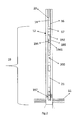
- Figure 1 illustrates an artificial simultaneous production and maintenance system assisted by mechanical pumping with flexible tubing for fluid extraction (100).
- Figure 1 shows a well (10) extending from the soil surface through the ground to connect with the reservoir (11).
- Oil or hydrocarbon of the reservoir (11) is extracted through the well (10).
- the artificial simultaneous production and maintenance system assisted by mechanical pumping with flexible tubing for fluid extraction (100) of the present invention is installed inside the well (10).
- This system includes a casing (12) extending across the well (10) from the surface until the reservoir (11).
- the artificial simultaneous production and maintenance system assisted by mechanical pumping with flexible tubing for fluid extraction (100) of the present invention works along with equipment mounted on the well surface by means of a surface assembly (30) which for that purpose includes a sub-base (513) and an hydraulic drive head (50).
- the equipment forms part of the state of the art and it is responsible to support the weight of the tubing for fluid circulation to the surface and downhole.
- the surface assembly (30) that forms part of the artificial simultaneous production and maintenance system assisted by mechanical pumping with flexible tubing for fluid extraction (100) includes: a stuffing box system (510) to control production fluids outside, as well as a preventer (511) with O-ring seals, an a wedge preventer (512) to hold flexible tubing.
- a connection and splicing means (15) is found; it consists of a flange (bridle) joining the surface assembly (30) with a production tubing (16).
- the connection and spicing means (15) allows holding and locking the production tubing (16).
- the production tubing (16) extends vertically downwards inside the casing (12), being production tubing (16) inside the casing (12) concentrically one to each other. Likewise, from surface equipment a flexible tubing (14) extends vertically downwards, from there it is projected again to continue its original direction downwards inside the well bore (10).
- Flexible tubing (14) is located directly inside the production tubing (16), all along its length, being then the casing (12), production tubing (16) and flexible tubing concentric (14) to each other.
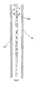
- FIG (2 ) sows a pump assembly (19) according to the present invention.
- Pump assembly (19) is fastened to the lower end of the flexible tubing (14), seated and anchored through a shoe connector (197) of the production tubing (16).
- Fastening between the pump assembly (19) and flexible tubing (14) is performed by a connector (17), link element located on the upper part of the pump assembly (19).
- the check valve (192) that prevents the extracted fluids to flow within the flexible tubing (14).
- the check valve (192) in turn is connected to a cleaning tool (194).
- the cleaning tool (194) includes on its surface a plurality of circulation ports (1941). These circulation ports (1941) consist of outlet holes for fluid and chemicals that will be pumped from the surface within the flexible tubing (14).
- the cleaning tool (194) is the element from the pump assembly (19) where the pumped liquids flow from the surface.
- This cleaning tool (194) is coupled by a blind connection (195) directly to the standing pump (21) of the pump assembly (19).
- the blind connection (195) is the only element of the pump assembly (19) where no fluid flows, whether from surface or directly extracted from the reservoir (11).
- Blind connection (195) is thread connected to the plunger pump (21) that allows, through the production holes (200), the exit of production fluid from the reservoir (11), to be pumped through the annular space (20) to the surface.
- the well extraction system is programmed for preventive and corrective maintenance, requiring disassembling the entire system for cleaning, changing pump, pipes, couples or other fixtures, which implies losses for stopping productive process and production times.
- FIG. 4 shows circulation pattern of chemicals and fluids inside the artificial simultaneous production and maintenance system (100) assisted by mechanical pumping with flexible tubing for fluid extraction. Fluids are pumped from the well surface by the surface equipment through the flexible tubing (14) until the cleaning tool (194), where the pumped fluid will exit through the circulation ports (1941). Such as we can observe from arrows representing fluid circulation in Figure 4 , the flow pumped inside the flexible tubing (14) returns again to the surface by flowing through the annular area (20) formed by both the flexible tubing (14) and production tubing (16).
- fluids to be pumped for well maintenance may be among others: necessary fluids for cleaning and desanding the well, chemicals to dissolve paraffin deposits, asphalts and scaling caused by carbonates, chemical fluids to modify several parameters of fluids coming from the reservoir as viscosity, density, etc.
- the artificial simultaneous production and maintenance system assisted by mechanical pumping with flexible tubing for fluid extraction (100) allows continuous injection of viscosity reducer agents to improve production during pump (21) operation. It is important to mention that pumping any of the above chemicals can be made during oil or hydrocarbon extraction from reservoir (11). In this way maintenance to the artificial simultaneous production and maintenance system assisted by mechanical pumping with flexible tubing for fluid extraction (100) can be applied in well (10), by pumping chemicals from the surface equipment to clean, dissolve paraffin, asphalt deposits, descaling mineral salts and reduce viscosity. Chemicals flow inside the flexible tubing (14) no needing to extract the mechanical pumping apparel, including the pump, which implies important savings in dead time of equipment of well (10).
- the artificial simultaneous production and maintenance system assisted by mechanical pumping with flexible tubing for fluid extraction (100) is a novel system requiring less installation and extraction time than any other conventional mechanical pumping system.
- the flexible tubing string (14) can be designed according to deepness, pressure and expected loads during operation, varying diameter, wall thickness and stiffness of the material.
- flexible tubing (14) bends or plies easily and is continuous, without connections or links, its installation and /or extraction is notably faster than a rod or coupling piping system.
- Figure (5 ) illustrates fluid circulation from reservoir (11) inside the artificial simultaneous production and maintenance system assisted by mechanical pumping with flexible tubing for fluid extraction.
- the fluid is pumped from the reservoir (11) to the oilwell surface through the pump assembly (19).
- Fluid production from reservoir (11) enters through the plunger pump (21), located on the lower portion of the pump assembly (19), and exits trough production holes (200) towards the annular space (20) for subsequent flow to the surface through the annular space (20) formed between the interior of production tubing (16) and flexible tubing (14).
- the plunger pump located on the lower portion of the pump assembly (19)
- trough production holes (200) towards the annular space (20) for subsequent flow to the surface through the annular space (20) formed between the interior of production tubing (16) and flexible tubing (14).
- the artificial simultaneous production and maintenance system assisted by mechanical pumping with flexible tubing for fluid extraction (100) including a flexible tubing (14) substantially reduces maintenance costs in the well (10), due to easiness to pump chemicals and reduce frequency of interventions to repair the well.
- suspension of operation times of the well for cleaning and desanding are very reduced, because it is possible to add chemicals, like any of those herein mentioned above, during functioning of mechanical pumping; allowing thus optimization of production of well (10), and consequently saving costs when operating the well.
- the artificial simultaneous production and maintenance system assisted by mechanical pumping with flexible tubing for fluid extraction (100) of the present invention could vary in length, thickness and/or capacity of each element conforming the artificial simultaneous production and maintenance system assisted by mechanical pumping with flexible tubing for fluid extraction (100).
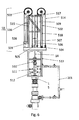
- Figure 6 shows the purpose for this head, which is to transfer the mechanical movement produced by an hydraulic power unit to the flexible tubing (14) to have an ascending and descending movement while the production tubing remains static inside the well. At the same time it is used to support all the weight of the flexible tubing (14) and the bottom assembly (19) shown in Figure 2 .
- Ascending movement produced by the hydraulic drive head (50) is originated by hydraulic flow received from a power unit not shown in the figures. Hydraulic flow is received through hydraulic connections (501); said hydraulic flow extends the hydraulic pistons (502) lengthwise making the steel cables (514) to go through a pulley set (503) and lift a guide car (505), which in turn lifts the flexible tubing (14); this later is fastened to the guide car by a clamp set (506).
- Descending movement produced by the hydraulic drive head (50) is originated by emptying the hydraulic fluid of hydraulic pistons (502) in a controlled way by the same hydraulic power unit. This movement is performed in reverse to the ascending movement previously described.
- Another function of the hydraulic head (50) is to permit introduction of fluid or chemical to the well by the flexible tubing (14). This happens by pumping the fluids or chemicals through a pumping connection (504) known as type (1502), the fluid is transferred to a fixed metal pipe (518) fastened to the metallic structure (515). This pipe is connected to a flexible hose by a rotary connection (517) and the other end of the hose (509) is connected to the flexible tubing (14) by another rotary connection (508) and a high pressure connector (507), and signaling as a basic element the discharge tubing (201), where the final product circulates (derived from the flow obtained in the well).
- a pumping connection known as type (1502
- This pipe is connected to a flexible hose by a rotary connection (517) and the other end of the hose (509) is connected to the flexible tubing (14) by another rotary connection (508) and a high pressure connector (507), and signaling as a basic element the discharge tubing (201), where the final product circulates (
Landscapes
- Engineering & Computer Science (AREA)
- Life Sciences & Earth Sciences (AREA)
- Geology (AREA)
- Mining & Mineral Resources (AREA)
- Physics & Mathematics (AREA)
- Environmental & Geological Engineering (AREA)
- Fluid Mechanics (AREA)
- General Life Sciences & Earth Sciences (AREA)
- Geochemistry & Mineralogy (AREA)
- Chemical Kinetics & Catalysis (AREA)
- Chemical & Material Sciences (AREA)
- General Chemical & Material Sciences (AREA)
- Mechanical Engineering (AREA)
- Details Of Reciprocating Pumps (AREA)
- Prostheses (AREA)
- Extraction Or Liquid Replacement (AREA)
- Jet Pumps And Other Pumps (AREA)
- Pipeline Systems (AREA)
- Loading And Unloading Of Fuel Tanks Or Ships (AREA)
- Cleaning In General (AREA)
- External Artificial Organs (AREA)
Applications Claiming Priority (2)
| Application Number | Priority Date | Filing Date | Title |
|---|---|---|---|
| MX2010012619A MX2010012619A (es) | 2010-11-19 | 2010-11-19 | Sistema artificial de produccion y mantenimientio simultaneo asistido por bombeo mecanico para extraccion de fluidos. |
| PCT/IB2011/055187 WO2012066514A1 (fr) | 2010-11-19 | 2011-11-18 | Système artificiel de production et d'entretien simultané assisté par pompage mécanique à conduite flexible pour l'extraction de fluides |
Publications (2)
| Publication Number | Publication Date |
|---|---|
| EP2642068A1 true EP2642068A1 (fr) | 2013-09-25 |
| EP2642068A4 EP2642068A4 (fr) | 2018-01-10 |
Family
ID=46027463
Family Applications (1)
| Application Number | Title | Priority Date | Filing Date |
|---|---|---|---|
| EP11842369.8A Withdrawn EP2642068A4 (fr) | 2010-11-19 | 2011-11-18 | Système artificiel de production et d'entretien simultané assisté par pompage mécanique à conduite flexible pour l'extraction de fluides |
Country Status (11)
| Country | Link |
|---|---|
| US (1) | US9410404B2 (fr) |
| EP (1) | EP2642068A4 (fr) |
| CN (1) | CN103221633B (fr) |
| AR (1) | AR083930A1 (fr) |
| BR (1) | BR112013012345A2 (fr) |
| CA (1) | CA2818101C (fr) |
| CO (1) | CO7230335A2 (fr) |
| EA (1) | EA026845B1 (fr) |
| MX (1) | MX2010012619A (fr) |
| RU (1) | RU2013127628A (fr) |
| WO (1) | WO2012066514A1 (fr) |
Cited By (1)
| Publication number | Priority date | Publication date | Assignee | Title |
|---|---|---|---|---|
| CN114914075A (zh) * | 2022-06-17 | 2022-08-16 | 扬州大恒电气科技有限公司 | 一种变压器套管维护辅助设备 |
Families Citing this family (3)
| Publication number | Priority date | Publication date | Assignee | Title |
|---|---|---|---|---|
| US10005950B2 (en) * | 2013-12-13 | 2018-06-26 | Halliburton Energy Services, Inc. | Methods and systems for removing geothermal scale |
| CN109339741B (zh) * | 2018-09-12 | 2021-03-19 | 中国石油天然气股份有限公司 | 一种适用于三元复合驱抽油机井中性不返排循环清垢工艺流程 |
| CN119933538A (zh) * | 2023-11-03 | 2025-05-06 | 中国石油天然气股份有限公司 | 一种抽油机井液压举升更换光杆装置 |
Family Cites Families (20)
| Publication number | Priority date | Publication date | Assignee | Title |
|---|---|---|---|---|
| US3939910A (en) * | 1974-12-23 | 1976-02-24 | Gar Industries Ltd. | Stuffing box and blow out preventing device for polish rods of oil well pumping units |
| US4418609A (en) * | 1981-03-16 | 1983-12-06 | Wickline | Well pumping system |
| US4681167A (en) * | 1984-06-08 | 1987-07-21 | Soderberg Research & Development, Inc. | Apparatus and method for automatically and periodically introducing a fluid into a producing oil well |
| US5095976A (en) | 1988-11-08 | 1992-03-17 | Appleton Billy D | Tubing sand pump |
| FR2678021B1 (fr) * | 1991-06-21 | 1999-01-15 | Inst Francais Du Petrole | Appareil et installation pour le nettoyage de drains, notamment dans un puits de production petroliere. |
| AU3277495A (en) * | 1995-07-25 | 1997-02-26 | Downhole Systems Technology Canada | Safeguarded method and apparatus for fluid communication usig coiled tubing, with application to drill stem testing |
| US5865249A (en) * | 1997-04-11 | 1999-02-02 | Atlantic Richfield Company | Method and apparatus for washing a horizontal wellbore with coiled tubing |
| US5924490A (en) * | 1997-09-09 | 1999-07-20 | Stone; Roger K. | Well treatment tool and method of using the same |
| US6298917B1 (en) * | 1998-08-03 | 2001-10-09 | Camco International, Inc. | Coiled tubing system for combination with a submergible pump |
| US6220358B1 (en) * | 1999-05-19 | 2001-04-24 | Humberto F. Leniek, Sr. | Hollow tubing pumping system |
| US6520260B1 (en) * | 1999-10-27 | 2003-02-18 | Roger Stone | Well treatment tool and method of treating a well |
| US6298927B1 (en) * | 2000-03-17 | 2001-10-09 | Laibe Corporation | Pipe storage and handling system for a drilling rig |
| US6607607B2 (en) * | 2000-04-28 | 2003-08-19 | Bj Services Company | Coiled tubing wellbore cleanout |
| US6585049B2 (en) | 2001-08-27 | 2003-07-01 | Humberto F. Leniek, Sr. | Dual displacement pumping system suitable for fluid production from a well |
| CA2465111C (fr) * | 2001-10-22 | 2008-10-21 | Ion Peleanu | Procede de conditionnement de fluides de puits de forage et tige de pompage associee |
| US7475731B2 (en) | 2004-04-15 | 2009-01-13 | Production Control Services, Inc. | Sand plunger |
| US7195070B2 (en) * | 2004-07-15 | 2007-03-27 | Weatherford/Lamb, Inc. | Method and apparatus for downhole artificial lift system protection |
| EP1852571A1 (fr) | 2006-05-03 | 2007-11-07 | Services Pétroliers Schlumberger | Nettoyage d'un puits de forage à l'aide de pompes de fond |
| GB2440725B (en) * | 2006-08-11 | 2011-06-08 | Hydropath Holdings Ltd | Treating liquids in oil extraction |
| GB0701061D0 (en) * | 2007-01-19 | 2007-02-28 | Head Phillip | Wireline or coiled tubing deployed electric submersible pump |
-
2010
- 2010-11-19 MX MX2010012619A patent/MX2010012619A/es active IP Right Grant
-
2011
- 2011-11-16 US US13/297,990 patent/US9410404B2/en not_active Expired - Fee Related
- 2011-11-18 EA EA201300597A patent/EA026845B1/ru not_active IP Right Cessation
- 2011-11-18 RU RU2013127628/03A patent/RU2013127628A/ru not_active Application Discontinuation
- 2011-11-18 WO PCT/IB2011/055187 patent/WO2012066514A1/fr not_active Ceased
- 2011-11-18 EP EP11842369.8A patent/EP2642068A4/fr not_active Withdrawn
- 2011-11-18 BR BR112013012345A patent/BR112013012345A2/pt not_active Application Discontinuation
- 2011-11-18 CA CA2818101A patent/CA2818101C/fr not_active Expired - Fee Related
- 2011-11-18 AR ARP110104321A patent/AR083930A1/es not_active Application Discontinuation
- 2011-11-18 CN CN201180055773.4A patent/CN103221633B/zh not_active Expired - Fee Related
-
2013
- 2013-06-17 CO CO13143983A patent/CO7230335A2/es unknown
Cited By (1)
| Publication number | Priority date | Publication date | Assignee | Title |
|---|---|---|---|---|
| CN114914075A (zh) * | 2022-06-17 | 2022-08-16 | 扬州大恒电气科技有限公司 | 一种变压器套管维护辅助设备 |
Also Published As
| Publication number | Publication date |
|---|---|
| US20120125599A1 (en) | 2012-05-24 |
| MX2010012619A (es) | 2012-03-06 |
| CA2818101A1 (fr) | 2012-05-24 |
| EP2642068A4 (fr) | 2018-01-10 |
| EA201300597A1 (ru) | 2013-12-30 |
| CN103221633B (zh) | 2016-08-24 |
| CN103221633A (zh) | 2013-07-24 |
| AU2011330738A1 (en) | 2013-07-11 |
| RU2013127628A (ru) | 2014-12-27 |
| CO7230335A2 (es) | 2015-03-31 |
| BR112013012345A2 (pt) | 2016-08-23 |
| AU2011330738A8 (en) | 2016-08-25 |
| AU2011330738B2 (en) | 2016-08-11 |
| CA2818101C (fr) | 2019-05-21 |
| AR083930A1 (es) | 2013-04-10 |
| EA026845B1 (ru) | 2017-05-31 |
| US9410404B2 (en) | 2016-08-09 |
| WO2012066514A1 (fr) | 2012-05-24 |
| WO2012066514A4 (fr) | 2012-08-16 |
Similar Documents
| Publication | Publication Date | Title |
|---|---|---|
| US8985221B2 (en) | System and method for production of reservoir fluids | |
| CA2738500C (fr) | Systeme d'entrainement continu de pompe a tiges | |
| US6089832A (en) | Through-tubing, retrievable downhole pump system | |
| CA2415446C (fr) | Mecanisme d'entrainement hydraulique de tete de puits | |
| US8708040B2 (en) | Double string pump for hydrocarbon wells | |
| US7647962B2 (en) | Assembly and method of alternative pumping using hollow rods without tubing | |
| US10760347B2 (en) | System and method for offline suspension or cementing of tubulars | |
| US9410404B2 (en) | Artificial simultaneous production and maintenance system assisted by mechanical pumping with flexible tubing for fluid extraction | |
| CA2778018C (fr) | Tige polie pourvue d'une section de verrouillage | |
| AU2011330738B8 (en) | Artificial system for simultaneous production and maintenance with mechanical pumping with flexible pipe for fluid extraction | |
| Alfarge | The Performance of Sucker Rod Pump Based Artificial Lift System in Oil Reservoirs: A Review | |
| US20200347876A1 (en) | Foldable Walking Beam for Sucker Rod Pumping Systems | |
| CA2551315A1 (fr) | Ensemble de pompage alternatif et methode avec tiges de pompage creuses et colonne de tubage a sec | |
| OA16702A (en) | System and method for production of reservoir fluids. | |
| OA21231A (en) | A Continuous Rod Pump Drive System. |
Legal Events
| Date | Code | Title | Description |
|---|---|---|---|
| PUAI | Public reference made under article 153(3) epc to a published international application that has entered the european phase |
Free format text: ORIGINAL CODE: 0009012 |
|
| 17P | Request for examination filed |
Effective date: 20130522 |
|
| AK | Designated contracting states |
Kind code of ref document: A1 Designated state(s): AL AT BE BG CH CY CZ DE DK EE ES FI FR GB GR HR HU IE IS IT LI LT LU LV MC MK MT NL NO PL PT RO RS SE SI SK SM TR |
|
| DAX | Request for extension of the european patent (deleted) | ||
| RIN1 | Information on inventor provided before grant (corrected) |
Inventor name: HAMMOND BRAVO, WILLIAM, ANTHONY |
|
| RA4 | Supplementary search report drawn up and despatched (corrected) |
Effective date: 20171207 |
|
| RIC1 | Information provided on ipc code assigned before grant |
Ipc: E21B 41/02 20060101ALI20171201BHEP Ipc: E21B 37/06 20060101AFI20171201BHEP Ipc: E21B 43/12 20060101ALI20171201BHEP |
|
| GRAP | Despatch of communication of intention to grant a patent |
Free format text: ORIGINAL CODE: EPIDOSNIGR1 |
|
| INTG | Intention to grant announced |
Effective date: 20181113 |
|
| RIN1 | Information on inventor provided before grant (corrected) |
Inventor name: HAMMOND BRAVO, WILLIAM ANTHONY |
|
| STAA | Information on the status of an ep patent application or granted ep patent |
Free format text: STATUS: THE APPLICATION IS DEEMED TO BE WITHDRAWN |
|
| 18D | Application deemed to be withdrawn |
Effective date: 20190326 |