EP2642145A1 - Wälzlager und verfahren zur herstellung eines wälzlagers - Google Patents
Wälzlager und verfahren zur herstellung eines wälzlagers Download PDFInfo
- Publication number
- EP2642145A1 EP2642145A1 EP11840850.9A EP11840850A EP2642145A1 EP 2642145 A1 EP2642145 A1 EP 2642145A1 EP 11840850 A EP11840850 A EP 11840850A EP 2642145 A1 EP2642145 A1 EP 2642145A1
- Authority
- EP
- European Patent Office
- Prior art keywords
- bearing
- raceway
- rolling
- rolling bearing
- rolling elements
- Prior art date
- Legal status (The legal status is an assumption and is not a legal conclusion. Google has not performed a legal analysis and makes no representation as to the accuracy of the status listed.)
- Withdrawn
Links
Images









Classifications
-
- C—CHEMISTRY; METALLURGY
- C23—COATING METALLIC MATERIAL; COATING MATERIAL WITH METALLIC MATERIAL; CHEMICAL SURFACE TREATMENT; DIFFUSION TREATMENT OF METALLIC MATERIAL; COATING BY VACUUM EVAPORATION, BY SPUTTERING, BY ION IMPLANTATION OR BY CHEMICAL VAPOUR DEPOSITION, IN GENERAL; INHIBITING CORROSION OF METALLIC MATERIAL OR INCRUSTATION IN GENERAL
- C23C—COATING METALLIC MATERIAL; COATING MATERIAL WITH METALLIC MATERIAL; SURFACE TREATMENT OF METALLIC MATERIAL BY DIFFUSION INTO THE SURFACE, BY CHEMICAL CONVERSION OR SUBSTITUTION; COATING BY VACUUM EVAPORATION, BY SPUTTERING, BY ION IMPLANTATION OR BY CHEMICAL VAPOUR DEPOSITION, IN GENERAL
- C23C8/00—Solid state diffusion of only non-metal elements into metallic material surfaces; Chemical surface treatment of metallic material by reaction of the surface with a reactive gas, leaving reaction products of surface material in the coating, e.g. conversion coatings, passivation of metals
- C23C8/06—Solid state diffusion of only non-metal elements into metallic material surfaces; Chemical surface treatment of metallic material by reaction of the surface with a reactive gas, leaving reaction products of surface material in the coating, e.g. conversion coatings, passivation of metals using gases
- C23C8/28—Solid state diffusion of only non-metal elements into metallic material surfaces; Chemical surface treatment of metallic material by reaction of the surface with a reactive gas, leaving reaction products of surface material in the coating, e.g. conversion coatings, passivation of metals using gases more than one element being applied in one step
- C23C8/30—Carbo-nitriding
- C23C8/32—Carbo-nitriding of ferrous surfaces
-
- C—CHEMISTRY; METALLURGY
- C21—METALLURGY OF IRON
- C21D—MODIFYING THE PHYSICAL STRUCTURE OF FERROUS METALS; GENERAL DEVICES FOR HEAT TREATMENT OF FERROUS OR NON-FERROUS METALS OR ALLOYS; MAKING METAL MALLEABLE, e.g. BY DECARBURISATION OR TEMPERING
- C21D1/00—General methods or devices for heat treatment, e.g. annealing, hardening, quenching or tempering
- C21D1/06—Surface hardening
-
- C—CHEMISTRY; METALLURGY
- C21—METALLURGY OF IRON
- C21D—MODIFYING THE PHYSICAL STRUCTURE OF FERROUS METALS; GENERAL DEVICES FOR HEAT TREATMENT OF FERROUS OR NON-FERROUS METALS OR ALLOYS; MAKING METAL MALLEABLE, e.g. BY DECARBURISATION OR TEMPERING
- C21D1/00—General methods or devices for heat treatment, e.g. annealing, hardening, quenching or tempering
- C21D1/74—Methods of treatment in inert gas, controlled atmosphere, vacuum or pulverulent material
- C21D1/76—Adjusting the composition of the atmosphere
-
- C—CHEMISTRY; METALLURGY
- C21—METALLURGY OF IRON
- C21D—MODIFYING THE PHYSICAL STRUCTURE OF FERROUS METALS; GENERAL DEVICES FOR HEAT TREATMENT OF FERROUS OR NON-FERROUS METALS OR ALLOYS; MAKING METAL MALLEABLE, e.g. BY DECARBURISATION OR TEMPERING
- C21D9/00—Heat treatment, e.g. annealing, hardening, quenching or tempering, adapted for particular articles; Furnaces therefor
- C21D9/40—Heat treatment, e.g. annealing, hardening, quenching or tempering, adapted for particular articles; Furnaces therefor for rings; for bearing races
-
- C—CHEMISTRY; METALLURGY
- C23—COATING METALLIC MATERIAL; COATING MATERIAL WITH METALLIC MATERIAL; CHEMICAL SURFACE TREATMENT; DIFFUSION TREATMENT OF METALLIC MATERIAL; COATING BY VACUUM EVAPORATION, BY SPUTTERING, BY ION IMPLANTATION OR BY CHEMICAL VAPOUR DEPOSITION, IN GENERAL; INHIBITING CORROSION OF METALLIC MATERIAL OR INCRUSTATION IN GENERAL
- C23C—COATING METALLIC MATERIAL; COATING MATERIAL WITH METALLIC MATERIAL; SURFACE TREATMENT OF METALLIC MATERIAL BY DIFFUSION INTO THE SURFACE, BY CHEMICAL CONVERSION OR SUBSTITUTION; COATING BY VACUUM EVAPORATION, BY SPUTTERING, BY ION IMPLANTATION OR BY CHEMICAL VAPOUR DEPOSITION, IN GENERAL
- C23C8/00—Solid state diffusion of only non-metal elements into metallic material surfaces; Chemical surface treatment of metallic material by reaction of the surface with a reactive gas, leaving reaction products of surface material in the coating, e.g. conversion coatings, passivation of metals
- C23C8/06—Solid state diffusion of only non-metal elements into metallic material surfaces; Chemical surface treatment of metallic material by reaction of the surface with a reactive gas, leaving reaction products of surface material in the coating, e.g. conversion coatings, passivation of metals using gases
- C23C8/08—Solid state diffusion of only non-metal elements into metallic material surfaces; Chemical surface treatment of metallic material by reaction of the surface with a reactive gas, leaving reaction products of surface material in the coating, e.g. conversion coatings, passivation of metals using gases only one element being applied
- C23C8/24—Nitriding
- C23C8/26—Nitriding of ferrous surfaces
-
- F—MECHANICAL ENGINEERING; LIGHTING; HEATING; WEAPONS; BLASTING
- F16—ENGINEERING ELEMENTS AND UNITS; GENERAL MEASURES FOR PRODUCING AND MAINTAINING EFFECTIVE FUNCTIONING OF MACHINES OR INSTALLATIONS; THERMAL INSULATION IN GENERAL
- F16C—SHAFTS; FLEXIBLE SHAFTS; ELEMENTS OR CRANKSHAFT MECHANISMS; ROTARY BODIES OTHER THAN GEARING ELEMENTS; BEARINGS
- F16C33/00—Parts of bearings; Special methods for making bearings or parts thereof
- F16C33/30—Parts of ball or roller bearings
- F16C33/58—Raceways; Race rings
- F16C33/62—Selection of substances
-
- F—MECHANICAL ENGINEERING; LIGHTING; HEATING; WEAPONS; BLASTING
- F16—ENGINEERING ELEMENTS AND UNITS; GENERAL MEASURES FOR PRODUCING AND MAINTAINING EFFECTIVE FUNCTIONING OF MACHINES OR INSTALLATIONS; THERMAL INSULATION IN GENERAL
- F16C—SHAFTS; FLEXIBLE SHAFTS; ELEMENTS OR CRANKSHAFT MECHANISMS; ROTARY BODIES OTHER THAN GEARING ELEMENTS; BEARINGS
- F16C19/00—Bearings with rolling contact, for exclusively rotary movement
-
- F—MECHANICAL ENGINEERING; LIGHTING; HEATING; WEAPONS; BLASTING
- F16—ENGINEERING ELEMENTS AND UNITS; GENERAL MEASURES FOR PRODUCING AND MAINTAINING EFFECTIVE FUNCTIONING OF MACHINES OR INSTALLATIONS; THERMAL INSULATION IN GENERAL
- F16C—SHAFTS; FLEXIBLE SHAFTS; ELEMENTS OR CRANKSHAFT MECHANISMS; ROTARY BODIES OTHER THAN GEARING ELEMENTS; BEARINGS
- F16C2202/00—Solid materials defined by their properties
- F16C2202/02—Mechanical properties
- F16C2202/04—Hardness
-
- F—MECHANICAL ENGINEERING; LIGHTING; HEATING; WEAPONS; BLASTING
- F16—ENGINEERING ELEMENTS AND UNITS; GENERAL MEASURES FOR PRODUCING AND MAINTAINING EFFECTIVE FUNCTIONING OF MACHINES OR INSTALLATIONS; THERMAL INSULATION IN GENERAL
- F16C—SHAFTS; FLEXIBLE SHAFTS; ELEMENTS OR CRANKSHAFT MECHANISMS; ROTARY BODIES OTHER THAN GEARING ELEMENTS; BEARINGS
- F16C2204/00—Metallic materials; Alloys
- F16C2204/60—Ferrous alloys, e.g. steel alloys
- F16C2204/66—High carbon steel, i.e. carbon content above 0.8 wt%, e.g. through-hardenable steel
-
- F—MECHANICAL ENGINEERING; LIGHTING; HEATING; WEAPONS; BLASTING
- F16—ENGINEERING ELEMENTS AND UNITS; GENERAL MEASURES FOR PRODUCING AND MAINTAINING EFFECTIVE FUNCTIONING OF MACHINES OR INSTALLATIONS; THERMAL INSULATION IN GENERAL
- F16C—SHAFTS; FLEXIBLE SHAFTS; ELEMENTS OR CRANKSHAFT MECHANISMS; ROTARY BODIES OTHER THAN GEARING ELEMENTS; BEARINGS
- F16C2204/00—Metallic materials; Alloys
- F16C2204/60—Ferrous alloys, e.g. steel alloys
- F16C2204/70—Ferrous alloys, e.g. steel alloys with chromium as the next major constituent
-
- F—MECHANICAL ENGINEERING; LIGHTING; HEATING; WEAPONS; BLASTING
- F16—ENGINEERING ELEMENTS AND UNITS; GENERAL MEASURES FOR PRODUCING AND MAINTAINING EFFECTIVE FUNCTIONING OF MACHINES OR INSTALLATIONS; THERMAL INSULATION IN GENERAL
- F16C—SHAFTS; FLEXIBLE SHAFTS; ELEMENTS OR CRANKSHAFT MECHANISMS; ROTARY BODIES OTHER THAN GEARING ELEMENTS; BEARINGS
- F16C2223/00—Surface treatments; Hardening; Coating
- F16C2223/10—Hardening, e.g. carburizing, carbo-nitriding
- F16C2223/14—Hardening, e.g. carburizing, carbo-nitriding with nitriding
Definitions
- the present invention relates to rolling bearings and methods of manufacturing the rolling bearings.
- rolling bearings will be operated under increasingly severe conditions in the future, such as a condition in which water penetration occurs, a condition in which a slip occurs, or a condition in which an electric current is passed. It is thus expected that rolling bearings highly resistant to hydrogen embrittlement will be required.
- Patent Document 1 discloses forming a Cr (chromium) oxide film as a passivation film to a prescribed thickness by setting a chromium content in a steel material to a prescribed value, thereby suppressing the penetration of hydrogen into the steel material.
- Non-Patent Document 1 discloses estimation of a dent-originating flaking life of steel having an accurately controlled nitrogen concentration.
- PTD 1 Japanese Patent Laying-Open No. 2000-282178
- NPD 1 Ohki et al., "Estimation of Scratched Contact Fatigue Life with Artificial Dent of SUJ2 Steel Carbonitrided to Controlled Surface Nitrogen Content," Tetsu-to-Hagané, October 2009, Vol. 95, No. 10, pp. 695-703
- the passivation film has the effect of delaying the diffusion of hydrogen, but also has the effect of facilitating the adsorption of produced hydrogen to the surface of steel. Therefore, for a rolling bearing used intermittently in which the hydrogen is dissipated when the bearing comes to a stop, delaying the penetration of hydrogen into the steel by the passivation film is considered effective in suppressing premature flaking. For a rolling bearing used successively, however, the passivation film adsorbs a large amount of hydrogen to increase the amount of hydrogen entering the steel, thus raising the possibility of premature flaking. It is expected that an increasing number of rolling bearings will be operated successively without human intervention in the future. Premature flaking particularly in such applications cannot be sufficiently suppressed by the conventional technique.
- a shaft When a bearing generates heat, a shaft is thermally expanded to contribute to deterioration of working accuracy.
- a machine tool main shaft rolling bearing used at high-speed rotation in a machine tool such as a machining center, it is important to reduce torque to avoid heat generation during the high-speed rotation. For this reason, the machine tool main shaft rolling bearing has a minimum amount of lubricant in order to reduce friction torque of the bearing that causes heat generation.
- an oil film has a smaller thickness than when a sufficient amount of lubricant is supplied, thus increasing a shear stress of the lubricant due to a slip. It is thus expected that hydrogen is readily produced.
- An angular contact ball bearing in particular is commonly used for a machine tool main shaft rolling bearing.
- the present invention was made in view of the aforementioned problems, and an object of the present invention is to provide a rolling bearing capable of suppressing premature flaking caused by hydrogen embrittlement.
- the present inventors found that, after extensive study, by nitriding a raceway surface of at least one bearing member of raceway members and rolling elements and by optimizing a tempering temperature of the bearing member to increase plastic deformation resistance and resistance to production of atomic vacancy, the hydrogen embrittlement resistance of a rolling bearing is improved.
- the at least one bearing member of the raceway members and the rolling elements the present inventors selected high-carbon chromium bearing steel SUJ2 (JIS standard) which is most commonly used for a rolling bearing, in view of material cost and availability.
- the present inventors nitrided and quenched the raceway surface of the bearing member, and then optimized the tempering temperature in order to improve the hydrogen embrittlement resistance. Nitriding the raceway surface of the bearing member increases the plastic deformation resistance of the bearing member. The present inventors found that nitriding the raceway surface of the bearing member increases the plastic deformation resistance of the bearing member, thereby improving the hydrogen embrittlement resistance of the bearing member.
- the basis for the optimization of the tempering temperature is a hydrogen-enhanced strain-induced vacancy theory, which is a leading hydrogen embrittlement mechanism. Plastic deformation increases atomic vacancy. This theory is based on a finding from scientific experiments that an increase in atomic vacancy density is enhanced when hydrogen is involved. Focusing on this theory, the present inventors found that the hydrogen embrittlement resistance is improved by optimization of the tempering temperature.
- One rolling bearing of the present invention includes a raceway member having an annular raceway, and a plurality of rolling elements being in contact with the raceway member and arranged on the annular raceway in a rollable manner. At least one bearing member of the raceway member and the rolling elements is made of JIS standard SUJ2. The bearing member has been quenched. The bearing member has a nitrided raceway surface. When a standard rolling bearing steel ball made of SUJ2 and having a diameter of 19.05 mm is pressed against the bearing member at a load of 3.18 kN and held for 10 seconds before the load is removed, a dent is formed in the bearing member at a depth of not more than 0.2 ⁇ m.
- the raceway surface has a Rockwell C scale hardness of not less than HRC 61.2 and not more than HRC 63.3.
- Nitriding the raceway surface of the bearing member increases the plastic deformation resistance of the bearing member. Nitriding the raceway surface of the bearing member increases the plastic deformation resistance of the bearing member, thereby improving the hydrogen embrittlement resistance of the bearing member.
- Plastic deformation increases atomic vacancy density.
- a dent depth shows a degree of plastic deformation resistance.
- a shallower dent depth means higher plastic deformation resistance.
- the plastic deformation resistance is high when a dent depth is not more than 0.2 ⁇ m.
- the raceway surface of the bearing member has a Rockwell C scale hardness of not less than HRC 61.2 and not more than HRC 63.3 when the tempering temperature is within a range of not less than 240°C and not more than 300°C.
- the bearing member having the nitrided raceway surface at a tempering temperature of not less than 240°C and not more than 300°C, the plastic deformation resistance and resistance to production of atomic vacancy can be increased.
- the hydrogen embrittlement resistance can be improved to suppress premature flaking caused by hydrogen embrittlement.
- the raceway surface has a surface-nitrided concentration of not less than 0.05% by mass and not more than 0.4% by mass.
- raceway surface has a surface-nitrided concentration of less than 0.05% by mass, a sufficient effect of extended life by the nitriding cannot be obtained. If the raceway surface has a surface-nitrided concentration of more than 0.4% by mass, a large amount of Cr carbonitrides is produced, resulting in lack of the amount of Cr contributing to hardenability. Thus, sufficient hardenability cannot be ensured. Accordingly, by setting the surface-nitrided concentration of the raceway surface to not less than 0.05% by mass and not more than 0.4% by mass, a sufficient effect of extended life by the nitriding can be obtained, to ensure sufficient hardenability.
- the present inventors selected non-nitrided JIS standard SUJ2 as the rolling elements in view of productivity.
- the plastic deformation resistance is high when a dent depth is not more than 0.2 ⁇ m.
- the entire rolling elements have a Rockwell C scale hardness of not less than HRC 57.0 and not more than HRC 58.9.
- the entire rolling elements have a Rockwell C scale hardness of not less than HRC 57.0 and not more than HRC 58.9 when the tempering temperature is within a range of not less than 240°C and not more than 280°C.
- the rolling elements are made of a material containing ceramic.
- the rolling elements are made of a material containing ceramic that does not exhibit hydrogen embrittlement.
- the hydrogen embrittlement resistance can be improved to suppress premature flaking caused by hydrogen embrittlement.
- the aforementioned one rolling bearing further includes a cage for holding the rolling elements, the cage being made of a material containing metal.
- the cage being made of a material containing metal.
- One method of manufacturing a rolling bearing of the present invention including a raceway member having an annular raceway, and a plurality of rolling elements being in contact with the raceway member and arranged on the annular raceway in a rollable manner, includes the following steps. At least one bearing member of the raceway member and the rolling elements which is made of a material of JIS standard SUJ2 is prepared. A raceway surface of the bearing member is nitrided and quenched. The quenched bearing member is tempered at not less than 240°C and not more than 300°C.
- Nitriding and quenching the raceway surface of the bearing member increases the plastic deformation resistance of the bearing member. Nitriding the raceway surface of the bearing member increases the plastic deformation resistance of the bearing member, thereby improving the hydrogen embrittlement resistance of the bearing member.
- the plastic deformation resistance of the bearing member and resistance to production of atomic vacancy in the bearing member can be increased.
- the hydrogen embrittlement resistance can be improved to suppress premature flaking caused by hydrogen embrittlement.
- the nitriding is performed at a temperature of 850°C in an atmosphere ofRX gas with ammonia gas introduced therein.
- the raceway surface of the bearing member is nitrided to a sufficient degree to increase the plastic deformation resistance of the bearing member, thereby improving the hydrogen embrittlement resistance of the bearing member.
- At least one bearing member of the raceway member and the rolling elements may be made of JIS standard SUJ3.
- the present inventors found that, after extensive study, by nitriding a raceway surface of at least one bearing member of raceway members and rolling elements and by optimizing a tempering temperature of the bearing member to increase plastic deformation resistance and resistance to production of atomic vacancy, the hydrogen embrittlement resistance of a rolling bearing is improved.
- the at least one bearing member of the raceway member and the rolling elements the present inventors selected high-carbon chromium bearing steel SUJ3 (JIS standard) which is commonly used for a rolling bearing, in view of material cost.
- the present inventors nitrided and quenched the raceway surface of the bearing member, and then optimized the tempering temperature in order to improve the hydrogen embrittlement resistance. Nitriding the raceway surface of the bearing member increases the plastic deformation resistance of the bearing member. The present inventors found that nitriding the raceway surface of the bearing member increases the plastic deformation resistance of the bearing member, thereby improving the hydrogen embrittlement resistance of the bearing member.
- the basis for the optimization of the tempering temperature is a hydrogen-enhanced strain-induced vacancy theory, which is a leading hydrogen embrittlement mechanism. Plastic deformation increases atomic vacancy. This theory is based on a finding from scientific experiments that an increase in atomic vacancy density is enhanced when hydrogen is involved. Focusing on this theory, the present inventors found that the hydrogen embrittlement resistance is improved by optimization of the tempering temperature.
- Another rolling bearing of the present invention includes a raceway member having an annular raceway, and a plurality of rolling elements being in contact with the raceway member and arranged on the annular raceway in a rollable manner.
- At least one bearing member of the raceway member and the rolling elements is made of JIS standard SUJ3.
- the bearing member has been quenched.
- the bearing member has a nitrided raceway surface.
- a standard rolling bearing steel ball made of SUJ2 and having a diameter of 19.05 mm is pressed against the bearing member at a load of 3.18 kN and held for 10 seconds before the load is removed, a dent is formed in the bearing member at a depth of not more than 0.1 ⁇ m.
- the raceway surface has a Rockwell C scale hardness of not less than HRC 60.5 and not more than HRC 62.1.
- Nitriding the raceway surface of the bearing member increases the plastic deformation resistance of the bearing member. Nitriding the raceway surface of the bearing member increases the plastic deformation resistance of the bearing member, thereby improving the hydrogen embrittlement resistance of the bearing member.
- Plastic deformation increases atomic vacancy density.
- a dent depth shows a degree of plastic deformation resistance.
- a shallow dent depth means high plastic deformation resistance.
- the plastic deformation resistance is high when a dent depth is not more than 0.1 ⁇ m.
- the raceway surface of the bearing member has a Rockwell C scale hardness of not less than HRC 60.5 and not more than HRC 62.1 when the tempering temperature is within a range of not less than 280°C and not more than 320°C.
- the bearing member having the nitrided raceway surface at a tempering temperature of not less than 280°C and not more than 320°C, the plastic deformation resistance and resistance to production of atomic vacancy can be increased.
- the hydrogen embrittlement resistance can be improved to suppress premature flaking caused by hydrogen embrittlement.
- the raceway surface has a surface-nitrided concentration of not less than 0.05% by mass and not more than 0.4% by mass.
- raceway surface has a surface-nitrided concentration of less than 0.05% by mass, a sufficient effect of extended life by the nitriding cannot be obtained. If the raceway surface has a surface-nitrided concentration of more than 0.4% by mass, a large amount of Cr carbonitrides is produced, resulting in lack of the amount of Cr contributing to hardenability. Thus, sufficient hardenability cannot be ensured. Accordingly, by setting the surface-nitrided concentration of the raceway surface to not less than 0.05% by mass and not more than 0.4% by mass, a sufficient effect of extended life by the nitriding can be obtained, to ensure sufficient hardenability.
- the present inventors selected high-carbon chromium bearing steel SUJ2 (JIS standard) as the rolling elements in view of material cost and availability.
- the present inventors nitrided and quenched the raceway surfaces of the rolling elements made of SUJ2, and then optimized the tempering temperature in order to improve the hydrogen embrittlement resistance.
- the rolling elements are made of JIS standard SUJ2.
- the rolling elements have been quenched.
- the rolling elements each have a nitrided raceway surface.
- a standard rolling bearing steel ball made of SUJ2 and having a diameter of 19.05 mm is pressed against the rolling elements at a load of 3.18 kN and held for 10 seconds before the load is removed, a dent is formed in the rolling elements at a depth of not more than 0.2 ⁇ m.
- the raceway surface has a Rockwell C scale hardness of not less than HRC 61.2 and not more than HRC 63.3.
- the plastic deformation resistance is high when a dent depth is not more than 0.2 ⁇ m.
- tempering is performed at not less than 240°C and not more than 300°C, when a standard rolling bearing steel ball made of SUJ2 and having a diameter of 19.05 mm is pressed against the rolling elements at a load of 3.18 kN and held for 10 seconds before the load is removed, a dent is formed in the rolling elements at a depth of not more than 0.2 ⁇ m.
- raceway surfaces of the rolling elements have a Rockwell C scale hardness of not less than HRC 61.2 and not more than HRC 63.3 when the tempering temperature is within a range of not less than 240°C and not more than 300°C
- the plastic deformation resistance and resistance to production of atomic vacancy can be increased.
- the hydrogen embrittlement resistance can be improved to suppress premature flaking caused by hydrogen embrittlement.
- the raceway surfaces of the rolling elements have a surface-nitrided concentration of not less than 0.05% by mass and not more than 0.4% by mass.
- raceway surfaces of the rolling elements have a surface-nitrided concentration of less than 0.05% by mass, a sufficient effect of extended life by the nitriding cannot be obtained. If the raceway surfaces of the rolling elements have a surface-nitrided concentration of more than 0.4% by mass, a large amount of Cr carbonitrides is produced, resulting in lack of the amount of Cr contributing to hardenability. Thus, sufficient hardenability cannot be ensured. Accordingly, by setting the surface-nitrided concentration of the raceway surfaces of the rolling elements to not less than 0.05% by mass and not more than 0.4% by mass, a sufficient effect of extended life by the nitriding can be obtained, to ensure sufficient hardenability.
- the present inventors selected non-nitrided JIS standard SUJ2 as the rolling elements in view of productivity.
- the plastic deformation resistance is high when a dent depth is not more than 0.2 ⁇ m.
- the entire rolling elements have a Rockwell C scale hardness of not less than HRC 57.0 and not more than HRC 58.9.
- the entire rolling elements have a Rockwell C scale hardness of not less than HRC 57.0 and not more than HRC 58.9 when the tempering temperature is within a range of not less than 240°C and not more than 280°C.
- the rolling elements are made of a material containing ceramic.
- the rolling elements are made of a material containing ceramic that does not exhibit hydrogen embrittlement.
- the hydrogen embrittlement resistance can be improved to suppress premature flaking caused by hydrogen embrittlement.
- the aforementioned another rolling bearing further includes a cage for holding the rolling elements, the cage being made of a material containing metal.
- the cage being made of a material containing metal.
- Another method of manufacturing a rolling bearing of the present invention including a raceway member having an annular raceway, and a plurality of rolling elements being in contact with the raceway member and arranged on the annular raceway in a rollable manner, includes the following steps. At least one bearing member of the raceway member and the rolling elements which is made of a material of JIS standard SUJ3 is prepared. A raceway surface of the bearing member is nitrided and quenched. The quenched bearing member is tempered at not less than 280°C and not more than 320°C.
- Nitriding and quenching the raceway surface of the bearing member increases the plastic deformation resistance of the bearing member. Nitriding the raceway surface of the bearing member increases the plastic deformation resistance of the bearing member, thereby improving the hydrogen embrittlement resistance of the bearing member.
- the plastic deformation resistance of the bearing member and resistance to production of atomic vacancy in the bearing member can be increased.
- the hydrogen embrittlement resistance can be improved to suppress premature flaking caused by hydrogen embrittlement.
- the nitriding is performed at a temperature of 850°C in an atmosphere ofRX gas with ammonia gas introduced therein.
- the raceway surface of the bearing member is nitrided to a sufficient degree to increase the plastic deformation resistance of the bearing member, thereby improving the hydrogen embrittlement resistance of the bearing member.
- the aforementioned one and another rolling bearings further include a main shaft of a motor and a housing arranged to be opposed to the outer peripheral surface of the main shaft, and supports the main shaft to be rotatable relative to the housing.
- the rolling bearing of the present invention premature flaking caused by hydrogen embrittlement can be suppressed, to provide a long-life motor rolling bearing under severe operating conditions such as a condition in which water penetrates the bearing, a condition in which a slip occurs, or a condition in which an electric current is passed.
- the aforementioned one and another rolling bearings further include a main shaft of a machine tool and a housing arranged to be opposed to the outer peripheral surface of the main shaft, and supports the main shaft to be rotatable relative to the housing.
- a long-life machine tool main shaft rolling bearing under severe operating conditions such as a condition in which water penetrates the bearing, a condition in which a slip occurs, or a condition in which an electric current is passed.
- a long-life machine tool main shaft rolling bearing can also be provided under an operating condition in which an oil film of lubricant has a reduced thickness in order to reduce friction torque of the bearing that causes heat generation during high-speed rotation.
- the aforementioned one and another rolling bearings further include a rotating-side member of a wheel and a fixed-side member arranged to be opposed to the outer peripheral surface of the rotating-side member, and supports the rotating-side member to be rotatable relative to the fixed-side member.
- premature flaking caused by hydrogen embrittlement can be suppressed, to provide a long-life wheel rolling bearing under severe operating conditions such as a condition in which water penetrates the bearing, a condition in which a slip occurs, or a condition in which an electric current is passed. Furthermore, premature flaking caused by hydrogen embrittlement can also be suppressed under a condition in which the bearing vibrates, to provide a long-life wheel rolling bearing.
- the aforementioned one and another rolling bearings further include a main shaft of an alternator and a housing arranged to be opposed to the outer peripheral surface of the main shaft, and supports the main shaft to be rotatable relative to the housing.
- premature flaking caused by hydrogen embrittlement can be suppressed, to provide a long-life alternator rolling bearing under severe operating conditions such as a condition in which water penetrates the bearing, a condition in which a slip occurs, or a condition in which an electric current is passed.
- Premature flaking caused by hydrogen embrittlement can be suppressed particularly under an operating condition in which premature flaking caused by hydrogen embrittlement readily occurs due to a slip between contact elements from rapid acceleration and deceleration, to provide a long-life alternator rolling bearing.
- premature flaking caused by hydrogen embrittlement can also be suppressed under a condition in which a slip is induced more readily than before due to an increase in applied load and an increase in load variation as a result of serpentinization, to provide a long-life alternator rolling bearing.
- the aforementioned one and another rolling bearings further include a main shaft and a pulley body arranged to be opposed to the outer peripheral surface of the main shaft, and supports the main shaft to be rotatable relative to the pulley body.
- premature flaking caused by hydrogen embrittlement can be suppressed, to provide a long-life pulley rolling bearing under severe operating conditions such as a condition in which water penetrates the bearing, a condition in which a slip occurs, or a condition in which an electric current is passed. Furthermore, premature flaking caused by hydrogen embrittlement can also be suppressed under a condition in which a slip is induced more readily than before due to an increase in applied load and an increase in load variation as a result of serpentinization, to provide a long-life pulley rolling bearing.
- the aforementioned one and another rolling bearings further include a car air conditioner electromagnetic clutch pulley and a pulley bearing support member arranged to be opposed to the inner peripheral surface of the car air conditioner electromagnetic clutch pulley, and supports the car air conditioner electromagnetic clutch pulley to be rotatable relative to the pulley bearing support member.
- premature flaking caused by hydrogen embrittlement can be suppressed, to provide a long-life car air conditioner electromagnetic clutch pulley rolling bearing under severe operating conditions such as a condition in which water penetrates the bearing, a condition in which a slip occurs, or a condition in which an electric current is passed. Furthermore, premature flaking caused by hydrogen embrittlement can also be suppressed under a condition in which a slip is induced more readily than before due to an increase in applied load and an increase in load variation as a result of serpentinization, to provide a long-life car air conditioner electromagnetic clutch pulley rolling bearing.
- the aforementioned one and another rolling bearings further include a pulley shaft of a continuously variable transmission and a housing arranged to be opposed to the outer peripheral surface of the pulley shaft, and supports the pulley shaft to be rotatable relative to the housing.
- premature flaking caused by hydrogen embrittlement can be suppressed, to provide a long-life continuously variable transmission rolling bearing under severe operating conditions such as a condition in which water penetrates the bearing, a condition in which a slip occurs, or a condition in which an electric current is passed. Furthermore, premature flaking caused by hydrogen embrittlement can also be suppressed under a condition in which a differential slip increases during bearing operation by setting a small curvature of groove of inner and outer rings of the bearing in order to reduce an axial clearance of the bearing, to provide a long-life continuously variable transmission rolling bearing.
- the rolling bearing is a shell type needle roller bearing.
- a slip occurs such as rapid acceleration and deceleration, particularly when used to support an air compressor of a vehicle rapidly accelerated and decelerated by switching of an electromagnetic clutch, when used to support an ABS (Antilock Brake System) pump rapidly accelerated during startup, or when used at a big end of a con rod of a versatile engine, a slip occurs readily in rolling elements, which may cause premature flaking caused by hydrogen embrittlement.
- the rolling bearing is a solid type needle roller bearing.
- a slip occurs such as rapid acceleration and deceleration, particularly when used to support an air compressor of a vehicle rapidly accelerated and decelerated by switching of an electromagnetic clutch, when used to support a transmission rapidly accelerated during startup, or when used at a big end of a con rod of a versatile engine, a slip occurs readily between contact elements, which may cause premature flaking caused by hydrogen embrittlement.
- the rolling bearing is a needle roller thrust bearing.
- a slip occurs constantly between rolling elements and rolling rings during operation due to the difference in peripheral speed between the inner and outer sides of the rolling elements, which may cause premature flaking caused by hydrogen embrittlement.
- premature flaking caused by hydrogen embrittlement may also occur under a condition in which a slip occurs such as rapid acceleration and deceleration. According to the rolling bearing of the present invention, premature flaking caused by hydrogen embrittlement can be suppressed under such conditions, to provide a long-life needle roller thrust bearing.
- the rolling bearing includes a cage.
- a slip occurs readily in rolling elements, which may cause premature flaking caused by hydrogen embrittlement.
- premature flaking caused by hydrogen embrittlement can be suppressed under such conditions, to provide a long-life needle roller bearing with a cage.
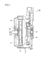
- a motor 90 in one embodiment of the present invention includes a rotor 91 having a discoidal shape and including a coil, a frame (housing) 93 arranged to enclose rotor 91, and a main shaft 92 connected to a part including the center (rotation axis) of rotor 91 while passing through frame 93, and constituted to be axially rotatable along with rotor 91.
- a grease-sealed deep groove ball bearing 1 as a motor rolling bearing is fitted between an outer peripheral surface 92A of main shaft 92 and a portion of frame 93 opposed to outer peripheral surface 92A of main shaft 92.
- grease-sealed deep groove ball bearing 1 is a motor rolling bearing supporting main shaft 92 of motor 90 to be rotatable relative to frame 93 arranged to be opposed to outer peripheral surface 92A of main shaft 92.
- Motor 90 further includes a stator 96 having a magnet arranged to be fixed to frame 93 to be opposed to the outer peripheral surface of rotor 91 in frame 93, a commutator 94 connected to a part of rotor 91 opposite to the side where main shaft 92 projects from frame 93 when viewed from rotor 91, and constituted to be rotatable along with rotor 91, and a brush 95 arranged to be fixed to frame 93 to be in contact with commutator 94.
- stator 96 having a magnet arranged to be fixed to frame 93 to be opposed to the outer peripheral surface of rotor 91 in frame 93
- a commutator 94 connected to a part of rotor 91 opposite to the side where main shaft 92 projects from frame 93 when viewed from rotor 91, and constituted to be rotatable along with rotor 91
- a brush 95 arranged to be fixed to frame 93 to be in contact with commutator 94.
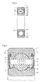
- grease-sealed deep groove ball bearing 1 includes an outer ring 11 as a first raceway member, an inner ring 12 as a second raceway member, balls 13 as a plurality of rolling elements, a cage 14, and sealing members 15.
- An outer ring raceway surface 11A as an annular first raceway surface is formed on the inner circumferential surface of outer ring 11.
- An inner ring raceway surface 12A as an annular second raceway surface opposed to outer ring raceway surface 11A is formed on the outer circumferential surface of inner ring 12.
- Ball raceway surfaces 13A (surfaces of balls 13) as rolling element raceway surfaces are formed on the plurality of balls 13.
- Balls 13 come into contact with outer ring raceway surface 11A and inner ring raceway surface 12A on ball raceway surfaces 13A, and are circumferentially arranged at a prescribed pitch by annular cage 14 to be held on an annular raceway in a rollable manner.
- the pair of sealing members 15 are arranged on opposite end portions in a width direction of outer ring 11 and inner ring 12, respectively, between outer ring 11 and inner ring 12, to close a space between outer ring 11 and inner ring 12, more specifically a raceway space which is a space between outer ring raceway surface 11A and inner ring raceway surfaces 12A.
- outer ring 11 and inner ring 12 of grease-sealed deep groove ball bearing 1 are rotatable relative to each other.
- a grease composition 16 is sealed in the aforementioned raceway space.
- At least one bearing member of outer ring 11, inner ring 12 as raceway members and balls 13 as rolling elements is made of JIS standard SUJ2.
- the at least one bearing member of outer ring 11, inner ring 12 as raceway members and balls 13 as rolling elements has been quenched.
- the at least one bearing member of outer ring 11, inner ring 12 as raceway members and balls 13 as rolling elements has a nitrided raceway surface 11A, 12A, 13A.
- a nitrided region NR is formed inward from the surfaces of outer ring 11, inner ring 12 and balls 13 as rolling elements. Although nitrided region NR is not illustrated in the following drawings, it is similarly formed inward from the surfaces of outer ring 11, inner ring 12 and balls 13 as rolling elements.
- Raceway surface 11A, 12A, 13A of the at least one bearing member of outer ring 11, inner ring 12 as raceway members and balls 13 as rolling elements has a surface-nitrided concentration of not less than 0.05% by mass and not more than 0.4% by mass.
- Non-nitrided JIS standard SUJ2 may be selected for balls 13 as rolling elements.
- a standard rolling bearing steel ball made of SUJ2 and having a diameter of 19.05 mm is pressed against balls 13 at a load of 1.97 kN and held for 10 seconds before the load is removed, a dent is formed in the bearing members at a depth of not more than 0.2 ⁇ m.
- the entire rolling elements have a Rockwell C scale hardness of not less than HRC 57.0 and not more than HRC 58.9.
- balls 13 as rolling elements be made of a material containing ceramic. Silicon nitride, sialon or the like may be adopted as the ceramic.
- the ceramic is a sintered body mainly composed of ⁇ sialon which is one sialon, the ceramic is sintered under low pressure (e.g., not more than 1 MPa), and can therefore be manufactured at lower cost than a sintered body mainly composed of silicon nitride which is pressured and sintered under a pressure of not less than 10 MPa.
- low pressure e.g., not more than 1 MPa
- the sintered body mainly composed of ⁇ sialon is a sintered body containing the ⁇ sialon as a main component and having a remainder formed of an impurity.
- the sialon is expressed in the composition formula of Si 6-Z AL Z N 8-Z , and composed such that Z satisfies the range of 0.1 ⁇ Z ⁇ 3.5.
- the impurity includes those derived from a source material or entering during the production process, and also includes an unavoidable impurity.
- As a sintering additive at least one of an oxide, a nitride and an oxynitride of magnesium (Mg), aluminum (Al), silicon (Si), titanium (Ti) and a rare earth element can be adopted. It is desirable that the sintering additive hold not more than 20% by mass of the sintered body.
- cage 14 for holding balls 13 as rolling elements be made of a material containing metal.
- a current supplied to brush 95 from a not-shown power source via wiring flows through the coil of rotor 91 through commutator 94.
- rotor 91 rotates around the axis of main shaft 92 relative to frame 93.
- the direction of the current flowing through the coil of rotor 91 is reversed by the action of commutator 94 and brush 95, causing further rotation of rotor 91.
- rotor 91 continuously rotates relative to the housing, and the rotation is taken out by main shaft 92.
- a steel material preparing step of preparing a steel material made of JIS standard SUJ2 is performed. Specifically, for example, steel bars and steel wires made of JIS standard SUJ2 are prepared.
- a forming step of preparing steel members formed into rough shapes of the bearing members of the motor rolling bearing is performed by forming the aforementioned steel material. Specifically, steel members formed into rough shapes of outer ring 11, inner ring 12 and balls 13 shown in Figs. 2 and 3 are prepared by performing working such as forging and machining on the aforementioned steel bars and steel wires.
- the aforementioned steps (S100) and (S200) constitute a steel member preparing step of preparing the steel members formed into rough shapes of the bearing members of the motor rolling bearing.
- a quench hardening step of quench hardening the steel members is performed by cooling the steel members from a temperature of not less than a point A1 to a temperature of not more than a point MS.
- a tempering step of tempering the quench hardened steel members is performed by heating the steel members to a temperature range of not less than 240°C and not more than 300°C.
- the aforementioned steps (S300) and (S400) constitute a heat treatment step of heat-treating the steel members. The details of this heat treatment step will be described later.
- a finishing step is performed. Specifically, finishing such as grinding is performed on the steel members subjected to the heat treatment step, whereby outer ring 11, inner ring 12 and balls 13 are finished.
- finishing such as grinding is performed on the steel members subjected to the heat treatment step, whereby outer ring 11, inner ring 12 and balls 13 are finished.
- an assembling step is performed. Specifically, outer ring 11, inner ring 12 and balls 13 prepared in the steps (S100) to (S500) are combined with separately prepared cage 14 and the like and assembled into grease-sealed deep groove ball bearing 1 as a motor rolling bearing in one embodiment of the present invention.
- the method of manufacturing the motor rolling bearing in one embodiment of the present invention is completed, and grease-sealed deep groove ball bearing 1 as a motor rolling bearing is completed.
- the transverse direction shows time, and indicates that the time elapses rightward.
- the vertical direction shows temperature, and indicates that the temperature increases upward.
- the steel members prepared in the step (S200) are first heated to a temperature T1 of not less than point A1, and held for a time t1. At this time, the steel members are heated in an atmosphere of RX gas with ammonia gas introduced therein, for example. Thus, the surfaces of the steel members to serve as the raceway surfaces of the bearing members are nitrided. Then, the steel members are dipped into oil (oil cooling), for example, to be cooled from the temperature of not less than point A1 to the temperature of not more than point MS. Thus, quenching is completed. The quench hardening step is completed through the aforementioned steps.
- the tempering step is performed by heating the quench hardened steel members to a temperature T2 of not more than point A1, holding the steel members for t2 and then air-cooling (standing to cool) the steel members to room temperature, for example.
- the heat treatment step in one embodiment of the present invention is completed through the aforementioned steps.
- Temperature T1 is a temperature of 850°C, for example. Time t1 is 180 minutes, for example.
- Temperature T2 is a temperature of not less than 240°C and not more than 300°C, for example. Time t2 is 120 minutes, for example.
- Point A1 denotes a point corresponding to a temperature at which the structure of steel starts transforming from ferrite to austenite when the steel is heated.
- Point MS denotes a point corresponding to a temperature at which the structure of steel starts transforming to martensite when austenited steel is cooled.
- the bearing members of the motor rolling bearing in one embodiment of the present invention in the steel member preparing step, steel members made of JIS standard SUJ2 are prepared in view of material cost and availability. Then, in the quench hardening step, quenching is performed as nitriding at a temperature of 850°C in an atmosphere of RX gas with ammonia gas introduced therein. Then, in the tempering step, tempering is performed by heating the steel members to not less than 240°C and not more than 300°C. Consequently, according to the aforementioned method of manufacturing the bearing members of the motor rolling bearing in one embodiment of the present invention, the plastic deformation resistance of the steel constituting the bearing members of the motor rolling bearing and resistance to production of atomic vacancy in the steel can be increased.
- the rolling elements may be made of non-nitrided JIS standard SUJ2 in view of productivity.
- a method of manufacturing a motor rolling bearing including rolling elements made of non-nitrided JIS standard SUJ2 will now be described.
- a steel material preparing step of preparing a steel material made of JIS standard SUJ2 is performed. Specifically, for example, steel bars and steel wires made of JIS standard SUJ2 are prepared.
- a forming step of preparing steel members formed into rough shapes of the rolling elements of the motor rolling bearing is performed by forming the aforementioned steel material. Specifically, steel members formed into rough shapes of balls 13 shown in Figs. 2 and 3 are prepared by performing working such as forging and machining on the aforementioned steel bars and steel wires.
- the aforementioned steps (S100) and (S200) constitute a steel member preparing step of preparing the steel members formed into rough shapes of the bearing members of the motor rolling bearing.
- a quench hardening step of quench hardening the steel members is performed by cooling the steel members from a temperature of not less than a point A1 to a temperature of not more than a point MS.
- a tempering step of tempering the quench hardened steel members is performed by heating the steel members to a temperature range of not less than 240°C and not more than 280°C.
- the aforementioned steps (S300) and (S400) constitute a heat treatment step of heat-treating the steel members. The details of this heat treatment step will be described later.
- a finishing step is performed. Specifically, finishing such as grinding is performed on the steel members subjected to the heat treatment step, whereby balls 13 are finished. Thus, balls 13 of the motor rolling bearing in one embodiment of the present invention are completed.
- a step (S600) an assembling step is performed. Specifically, balls 13 prepared in the steps (S100) to (S500) are combined with separately prepared outer ring 11, inner ring 12, cage 14 and the like and assembled into grease-sealed deep groove ball bearing 1 as a motor rolling bearing in one embodiment of the present invention.
- the method of manufacturing the motor rolling bearing including the rolling elements made of non-nitrided JIS standard SUJ2 in one embodiment of the present invention is completed, and grease-sealed deep groove ball bearing 1 as a motor rolling bearing is completed.
- the transverse direction shows time, and indicates that the time elapses rightward.
- the vertical direction shows temperature, and indicates that the temperature increases upward.
- the steel members prepared in the step (S200) are first heated to a temperature T1 of not less than point A1, and held for a time t1. At this time, the steel members are heated in an RX gas atmosphere, for example. Then, the steel members are dipped into oil (oil cooling), for example, to be cooled from the temperature of not less than point A1 to the temperature of not more than point MS. Thus, through hardening is completed. The quench hardening step is completed through the aforementioned steps.
- the tempering step is performed by heating the quench hardened steel members to a temperature T2 of not more than point A1, holding the steel members for t2 and then air-cooling (standing to cool) the steel members to room temperature, for example.
- the heat treatment step in one embodiment of the present invention is completed through the aforementioned steps.
- Temperature T1 is a temperature of 850°C, for example. Time t1 is 80 minutes, for example.
- Temperature T2 is a temperature of not less than 240°C and not more than 280°C, for example. Time t2 is 120 minutes, for example.
- a grease-sealed deep groove ball bearing has been described above as an example of the rolling bearing in one embodiment of the present invention.
- a motor has been described as an example of a device to which the rolling bearing in one embodiment of the present invention is applied.
- the rolling bearing in one embodiment of the present invention is not limited to the above description, but may be an angular contact ball bearing, a cylindrical roller bearing or the like.
- the rolling bearing in one embodiment of the present invention may be applied to a machine tool main shaft rolling bearing.
- An angular contact ball bearing and a cylindrical roller bearing will now be described as other examples of the rolling bearing in one embodiment of the present invention, and the structures of machine tolls including these bearings will be described.
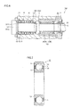
- a machine tool 100 in one embodiment of the present invention includes a main shaft 101 having a cylindrical shape, a housing 102 enclosing the outer peripheral surface of main shaft 101, and angular contact ball bearings 10 (front bearings) and a cylindrical roller bearing 20 (rear bearing) as machine tool main shaft rolling bearings arranged to be fitted between main shaft 101 and housing 102 such that the outer circumferential surfaces of their outer rings are in contact with an inner wall 102A of the housing and the inner circumferential surfaces of their inner rings are in contact with an outer peripheral surface 101A of main shaft 101.
- main shaft 101 is supported to be axially rotatable relative to housing 102.
- a motor rotor 103B is set on main shaft 101 to enclose part of outer peripheral surface 101A, while a motor stator 103A is set on inner wall 102A of housing 102 in a position opposed to motor rotor 103B.
- Motor stator 103A and motor rotor 103B constitute a motor 103 (built-in motor).
- main shaft 101 is rotatable relative to housing 102 due to power of motor 103.
- angular contact ball bearings 10 and cylindrical roller bearing 20 are machine tool main shaft rolling bearings supporting rotationally driven main shaft 101 to be rotatable relative to housing 102 which is a member arranged adjacently to main shaft 101 in machine tool 100 working a workpiece by rotation of main shaft 101.
- each angular contact ball bearing 10 includes an outer ring 11 as a first raceway member which is a bearing member of a machine tool main shaft rolling bearing, an inner ring 12 as a second raceway member, balls 13 as a plurality of rolling elements, and a cage 14.
- An outer ring raceway surface 11A as an annular first raceway surface is formed on outer ring 11.
- An inner ring raceway surface 12A as an annular second raceway surface opposed to outer ring raceway surface 11A is formed on inner ring 12.
- Ball raceway surfaces 13A (surfaces of balls 13) as rolling element raceway surfaces are formed on the plurality of balls 13.
- Balls 13 come into contact with outer ring raceway surface 11A and inner ring raceway surface 12A on ball raceway surfaces 13A, and are circumferentially arranged at a prescribed pitch by annular cage 14 to be held on an annular raceway in a rollable manner.
- outer ring 11 and inner ring 12 are rotatable relative to each other.
- two angular contact ball bearings 10 of the same direction are arranged on a front side (side of a tip 101B of main shaft 101) while two angular contact ball bearings 10 of a direction opposite to the front side are arranged on a rear side (side of motor rotor 103B) in machine tool 100 in one embodiment of the present invention, thereby canceling the component of force.
- cylindrical roller bearing 20 basically has a structure similar to that of the aforementioned angular contact ball bearing 10, and has a similar effect. In the structures of raceway members and rolling elements, however, cylindrical roller bearing 20 is different from angular contact ball bearing 10.
- cylindrical roller bearing 20 includes an outer ring 11 as a first raceway member which is a bearing member of a machine tool main shaft rolling bearing, an inner ring 12 as a second raceway member, cylindrical rollers 23 as a plurality of rolling elements, and a cage 14.
- An outer ring raceway surface 11A as an annular first raceway surface is formed on outer ring 11.
- An inner ring raceway surface 12A as an annular second raceway surface opposed to outer ring raceway surface 11A is formed on inner ring 12.
- Roller raceway surfaces 23A outer circumferential surfaces of cylindrical rollers 23) as rolling element raceway surfaces are formed on the plurality of cylindrical rollers 23.
- Cylindrical rollers 23 come into contact with outer ring raceway surface 11A and inner ring raceway surface 12A on roller raceway surfaces 23A, and are circumferentially arranged at a prescribed pitch by annular cage 14 to be held on an annular raceway in a rollable manner.
- outer ring 11 and inner ring 12 are rotatable relative to each other.
- a method of manufacturing the machine tool main shaft rolling bearing in one embodiment of the present invention is similar to the aforementioned method of manufacturing the motor rolling bearing except for the forming step.
- steel members formed into rough shapes of outer ring 11, inner ring 12, balls 13 and cylindrical rollers 13 shown in Figs. 7 and 8 are prepared. The description of the remaining steps of the manufacturing method will not be repeated.
- a lubrication device including a rolling bearing lubricated with a small amount of lubricant will be described as another example of the machine tool main shaft rolling bearing in one embodiment of the present invention.
- a lubrication device 40 mainly includes an angular contact ball bearing 30, a lubricant introducing member 31, a lid member 32, and an inner ring spacer 33.
- Fig. 9 shows a part around a portion where the lubricant is introduced and does not show a main shaft, a housing and the like to which lubrication device 40 is applied.
- Inner ring 12 of angular contact ball bearing 30 includes an oil receiving circumferential groove 34 for receiving lubricant discharged from lubricant introducing member 31.
- Oil receiving circumferential groove 34 is provided at an end surface adjacent to lubricant introducing member 31.
- a slope portion 12B having a larger diameter on the inner ring raceway surface 12A side is formed on an outer diameter surface of inner ring 12. Slope portion 12B is formed to guide the lubricant accumulated in oil receiving circumferential groove 34 to inner ring raceway surface 12A of inner ring 12 by centrifugal force acting on the lubricant and surface tension.
- Lubricant introducing member 31 includes a rib-shaped portion 31a extending axially from its side surface toward angular contact ball bearing 30.
- a sealing portion 31b is formed at the tip of rib-shaped portion 31a. Sealing portion 31b is arranged in the vicinity of ball 13 between the inner diameter surface of cage 14 and inner ring 12. Sealing portion 31b has an inner diameter surface formed as an inclined surface at an angle ⁇ the same as that of slope portion 12B of inner ring 12. Sealing portion 31b is arranged with a gap ⁇ from slope portion 12B of inner ring 12.
- Lubricant introducing member 31 includes a lubricant supply path 31c and a discharge outlet 31d. Lubricant supply path 31c is in communication with discharge outlet 31d. Discharge outlet 31d opens to be opposed to oil receiving circumferential groove 34 of inner ring 12.
- a drain oil circumferential groove 31e is formed to open to the inner diameter side. Drain oil circumferential groove 31e is in communication with a not-shown drain oil collection path, through which drain oil is collected.
- lubrication device 40 In lubrication device 40, a very small amount of the oil discharged from discharge outlet 31d of lubricant introducing member 31 is used as the lubricant for angular contact ball bearing 30, while most of the oil is supplied to cool inner ring 12.
- the very small amount of the oil discharged to oil receiving circumferential groove 34 of inner ring 12 is introduced into angular contact ball bearing 30 along slope portion 12B by centrifugal force associated with rotation of inner ring 12 and surface tension of the oil, to be used as the lubricant.
- a lubricant having very low viscosity corresponding to ISO VG2 is used, for example.
- a method of manufacturing this rolling bearing lubricated with a small amount of lubricant is similar to the aforementioned method of manufacturing the motor rolling bearing except for the forming step.
- steel members formed into rough shapes of outer ring 11, inner ring 12 and balls 13 shown in Fig. 9 are prepared. The description of the remaining steps of the manufacturing method will not be repeated.
- lubrication device 40 In lubrication device 40, a reduced amount of oil is used and further the low viscosity lubricant is utilized, thereby attaining reduced torque.
- a lubrication device including another rolling bearing lubricated with a small amount of lubricant will be further described.
- a lubrication device 60 mainly includes an angular contact ball bearing 50, a spacer 61, and a grease reservoir forming member 62.
- Fig. 10 shows a part around a portion where the lubricant is introduced and does not show a main shaft, a housing and the like to which lubrication device 60 is applied.
- Outer ring 11 of angular contact ball bearing 50 is provided with a stepped surface 11b extending away from ball 13 toward the outer diameter of outer ring 11.
- Grease reservoir forming member 62 is a ring-shaped member having a grease reservoir 63 for accumulating grease therein.
- An internal space between spacer 61 and grease reservoir forming member 62 constitutes grease reservoir 63.
- grease reservoir forming member 62 is positioned in the direction of the axis of a not-shown main shaft relative to spacer 61.
- a not-shown sealing member is interposed between spacer 61 and grease reservoir forming member 62. This sealing member prevents leakage of grease.
- a tip portion 62a of grease reservoir forming member 62 is arranged along the inner diameter surface of outer ring 11.
- the tip of tip portion 62a is arranged to be opposed to stepped surface 11b.
- a flow path 64 and a gap 65 are formed between tip portion 62a and outer ring 11.
- a peripheral wall of tip portion 62a and a portion of the inner diameter surface of outer ring 11 opposed to the peripheral surface form flow path 64.
- An end surface of tip portion 62a and stepped surface 11b opposed to the end surface form gap 65 having a minute amount of gap ⁇ in the direction of the axis of a not-shown main shaft.
- Gap 65 is in communication with flow path 64, and opens to an edge portion of the outer ring raceway surface.
- the amount of gap ⁇ of gap 65 is set to 0.05 to 0.1 mm, for example.
- An inner diameter surface continuous with the end surface of tip portion 62a has a tapered surface 66 adjacent to ball 13, to facilitate the accumulation of lubricant between tapered surface 66 and ball 13.
- the distance between tapered surface 66 and ball 13 is preferably a minimum gap having a size that allows the oil adhered to tapered surface 66 to be transferred to the surface of ball 13, and is set to not more than 0.2 mm, for example.
- a method of manufacturing this another rolling bearing lubricated with a small amount of lubricant is similar to the aforementioned method of manufacturing the motor rolling bearing except for the forming step.
- steel members formed into rough shapes of outer ring 11, inner ring 12 and balls 13 shown in Fig. 10 are prepared. The description of the remaining steps of the manufacturing method will not be repeated.
- lubrication device 60 In lubrication device 60, a small amount of base oil is introduced into angular contact ball bearing 50 from grease reservoir 63 by utilizing a capillary phenomenon. In this method, torque is not generated by stirring of a thickening agent of the grease by cage 14 and the like. Therefore, only a small amount of heat is generated, thereby allowing high-speed operation.
- the rolling bearing in one embodiment of the present invention may be applied to a wheel rolling bearing.
- a wheel rolling bearing will be described as another example of the rolling bearing in one embodiment of the present invention, and the structure of a wheel including this bearing will be described.
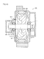
- a double row angular contact ball bearing 110 as a wheel rolling bearing supports a rotating-side member such as a hub wheel 113, which supports a wheel 120 (driving wheel) formed of a wheel 111 and a tire 112, to be rotatable relative to a fixed-side member such as a knuckle 114.
- Double row angular contact ball bearing 110 mainly includes an outer ring 11, an inner ring 12, balls 13, a cage 14, sealing members 15, and a magnetic encoder 115.
- Inner ring 12 fits on the outer peripheral surface of hub wheel 113, and outer ring 11 fits on the inner peripheral surface of knuckle 114.
- Outer ring 11 is formed of one member.
- Inner ring 12 is formed of two members.
- the plurality of balls 13 are arranged in double rows. The plurality of balls 13 come in contact with an outer ring raceway surface 11A and an inner ring raceway surface 12A at ball raceway surfaces 13A, and are circumferentially arranged at a prescribed pitch by comb-shaped cage 14 to be held on an annular raceway in a rollable manner.
- outer ring 11 and inner ring 12 are rotatable relative to each other.
- Straight lines connecting contact points between balls 13 and outer ring 11 and contact points between balls 13 and inner ring 12 form angles relative to a radial direction (direction perpendicular to a rotation axis of double row angular contact ball bearing 110).
- a component of force in an axial direction (direction of the rotation axis of double row angular contact ball bearing 110) is produced.
- Straight lines connecting contact points between ball 13 and outer ring 11 and contact points between adjacent ball 13 and inner ring 12 are arranged in opposite directions to cancel the component of force.
- Sealing members 15 are inserted between the inner diameter of outer ring 11 and the outer diameter of inner ring 12. Sealing members 15 can prevent leakage of oil from inside of the double row angular contact ball bearing, or penetration of foreign objects and water from outside of the double row angular contact ball bearing.
- Magnetic encoder 115 is press-fit into an outer diameter end portion of inner ring 12, and has a magnetic member, which is circumferentially multipolar magnetized in such state, closely confronting a magnetic sensor 116 fixed to knuckle 114. Thus, the rotational speed of the wheel can be accurately detected.
- Wheel 120 rotates by rotation of the rotating-side member such as hub wheel 113 relative to the fixed-side member such as knuckle 114.
- a method of manufacturing the wheel rolling bearing in one embodiment of the present invention is similar to the aforementioned method of manufacturing the motor rolling bearing except for the forming step.
- steel members formed into rough shapes of outer ring 11, inner ring 12 and balls 13 shown in Fig. 12 are prepared. The description of the remaining steps of the manufacturing method will not be repeated.
- a motor rolling bearing a machine tool main shaft rolling bearing, a wheel rolling bearing, a grease-sealed deep groove ball bearing, an angular contact ball bearing, a cylindrical roller bearing, a double row angular contact ball bearing, and raceway members and rolling elements included in these bearings have been described as examples.
- the rolling bearing and its bearing members of the present invention are not limited as such, but may be a rolling bearing and its raceway members and rolling elements.
- the rolling bearing in another embodiment may be a radial bearing or a thrust bearing.
- the raceway members include an outer ring, an inner ring and the like.
- the rolling elements may form raceway surfaces between themselves and the inner ring, the outer ring and a raceway washer.
- the rolling elements include balls, cylindrical rollers, tapered rollers and the like.
- JIS standard SUJ2 JIS standard SUJ2
- 52100 AISI or SAE standard
- 100Cr6 DIN standard
- GCr15 GBB standard
- the rolling bearing in one embodiment of the present invention may be applied to an alternator rolling bearing.
- an alternator rolling bearing will be described as another example of the rolling bearing in one embodiment of the present invention, and the structure of an alternator including this bearing will be described.
- an alternator 200 in one embodiment of the present invention includes a shaft (main shaft) 201, a rotor 202, a stator 203, a pulley 204, a housing 205, and a grease-sealed deep groove ball bearing 1 as an alternator rolling bearing.
- Housing 205 is arranged to enclose rotor 202.
- Shaft 201 is arranged to pass through a central portion of rotor 202 and to pass through a wall surface of housing 205.
- Stator 203 is arranged to be opposed to the outer peripheral surface of rotor 202 in housing 205.
- Housing 205 is arranged to be opposed to part of the outer peripheral surface of one end portion of shaft 201.
- Grease-sealed deep groove ball bearing 1 as an alternator rolling bearing is arranged between shaft 201 and housing 205.
- Grease-sealed deep groove ball bearing 1 supports shaft 201 to be rotatable relative to housing 205.
- Annular pulley 204 is attached, outside of housing 205, to a tip portion of the one end portion of shaft 201.
- the outer peripheral surface of pulley 204 is provided with an engagement groove 206 around which a not-shown transmission belt is provided.
- This grease-sealed deep groove ball bearing 1 as an alternator rolling bearing has a structure similar to that of the aforementioned grease-sealed deep groove ball bearing 1 as a motor rolling bearing in one embodiment of the present invention.
- Grease-sealed deep groove ball bearing 1 as an alternator rolling bearing is an automotive electrical and auxiliary component rolling bearing, for example.
- alternator 200 operated with power generated by a power source such as a not-shown engine
- grease-sealed deep groove ball bearing 1 supports shaft 201 rotationally driven by this power to be rotatable relative to adjacently arranged housing 205.
- grease-sealed deep groove ball bearing 1 arranged at one end portion of shaft 201 between rotor 202 and pulley 204 is referred to as a front bearing.
- Grease-sealed deep groove ball bearing 1 arranged at the other end portion of shaft 201 is referred to as a rear bearing.
- Hydrogen embrittlement flaking occurs more readily in grease-sealed deep groove ball bearing 1 as the front bearing which is subjected to large stress such a bending moment, than in grease-sealed deep groove ball bearing 1 as the rear bearing.
- alternator 200 The operation of alternator 200 is now described.
- the not-shown transmission belt rotated by power from a power source such as a not-shown engine is provided around the outer peripheral surface of pulley 204 provided with engagement groove 206.
- pulley 204 rotates, along with shaft 201 pivotally supported by grease-sealed deep groove ball bearings 1 relative to housing 205, around the axis of shaft 201.
- Rotor 202 rotates along with shaft 201 around the axis of shaft 201.
- rotor 202 rotates relative to stator 203 opposed to the outer peripheral surface of rotor 202 and arranged to be fixed to housing 205. Consequently, an electromotive force is generated in the coil of stator 203 due to electromagnetic induction between rotor 202 and stator 203.
- a method of manufacturing this grease-sealed deep groove ball bearing 1 as an alternator rolling bearing is similar to the aforementioned method of manufacturing grease-sealed deep groove ball bearing 1 as a motor rolling bearing in one embodiment of the present invention.
- a belt for driving electrical and auxiliary components including an alternator has been serpentinized with the recent trend for space saving.
- the serpentinization as used herein refers to driving a plurality of auxiliary components with one belt.
- the serpentinization eliminates the need the provide a belt for each auxiliary component, thereby saving space.
- the serpentinization tends to increase an applied load and load variation, causing a slip to be induced more readily than before.
- Grease-sealed deep groove ball bearing 1 as an alternator rolling bearing is used for rotation of the inner ring, thus increasing load rotation of part of outer ring 11. Accordingly, premature flaking caused by hydrogen embrittlement readily occurs in that part of outer ring 11. It is thus preferable to apply the bearing member in one embodiment of the present invention to outer ring 11.
- the rolling bearing in one embodiment of the present invention may be applied to a pulley rolling bearing.
- a pulley rolling bearing will be described as another example of the rolling bearing in one embodiment of the present invention, and the structure of a pulley including this bearing will be described.
- a pulley 210 in one embodiment of the present invention includes a pulley body 211, and a grease-sealed deep groove ball bearing 1 as a pulley rolling bearing.
- Pulley body 211 has an annular shape.
- the outer peripheral surface of pulley body 211 is provided with a transmission belt provision portion 212 around which a not-shown transmission belt is provided.
- a central portion on the inner diameter side of pulley body 211 is provided with a through hole 213 through which a shaft (main shaft) 218 passes.
- Grease-sealed deep groove ball bearing 1 is fitted into pulley body 211 such that the inner peripheral surface of through hole 213 is in contact with an outer ring 11 of grease-sealed deep groove ball bearing 1.
- pulley body 211 includes a cylindrical inner peripheral cylindrical portion 214 having an inner peripheral surface provided with the through hole, a flange portion 215 extending radially outward from one end portion in a width direction (axial direction) of inner peripheral cylindrical portion 214, an outer peripheral cylindrical portion 216 extending in the width direction (axial direction) from flange portion 215, and a rib portion 217 extending radially inward from the other end portion in the width direction (axial direction) of inner peripheral cylindrical portion 214.
- Outer ring 11 of grease-sealed deep groove ball bearing 1 is fitted to be in contact with inner peripheral cylindrical portion 214 and rib portion 217 of pulley body 211.
- Shaft 218 is fitted and attached to an inner ring 12 of grease-sealed deep groove ball bearing 1.
- This grease-sealed deep groove ball bearing 1 as a pulley rolling bearing has a structure similar to that of the aforementioned grease-sealed deep groove ball bearing 1 as a motor rolling bearing in one embodiment of the present invention.
- Grease-sealed deep groove ball bearing 1 as a pulley rolling bearing is an automotive electrical and auxiliary component rolling bearing, for example.
- pulley 210 operated with power generated by a power source such as a not-shown engine
- grease-sealed deep groove ball bearing 1 supports pulley body 211 rotationally driven by this power to be rotatable relative to shaft 218 passing through pulley 210.
- pulley 210 The operation of pulley 210 is now described.
- the not-shown transmission belt rotated by power from a power source such as a not-shown engine is provided around the outer peripheral surface of pulley body 211 provided with transmission belt provision portion 212.
- pulley 210 rotates, along with shaft 218 pivotally supported by grease-sealed deep groove ball bearings 1, around the axis of shaft 218.
- pulley 210 can function as a tensioner for providing the transmission belt with tension when the distance is fixed between shafts around which the transmission belt is provided.
- pulley 210 can function as an idler for changing a traveling direction of the transmission belt in order to avoid contact with various devices that are obstacles in an engine room.
- a method of manufacturing this grease-sealed deep groove ball bearing 1 as a pulley rolling bearing is similar to the method of manufacturing the aforementioned grease-sealed deep groove ball bearing 1 as a motor rolling bearing in one embodiment of the present invention.
- a belt for driving electrical and auxiliary components including a pulley has been serpentinized with the recent trend for space saving.
- the serpentinization tends to increase an applied load and load variation, causing a slip to be induced more readily than before.
- Grease-sealed deep groove ball bearing 1 as a pulley rolling bearing is used for rotation of the outer ring, thus increasing load rotation of part of inner ring 12. Accordingly, premature flaking caused by hydrogen embrittlement readily occurs in that part of inner ring 12. It is thus preferable to apply the bearing member in one embodiment of the present invention to inner ring 12.
- the rolling bearing in one embodiment of the present invention may be applied to a car air conditioner electromagnetic clutch pulley rolling bearing.
- a car air conditioner electromagnetic clutch pulley rolling bearing will be described as another example of the rolling bearing in one embodiment of the present invention, and a compressor with a car air conditioner electromagnetic clutch pulley mechanism including this bearing will be described.
- this compressor includes a single swash plate-type swash plate compressor 220 and a compressor pulley mechanism 230.
- Single swash plate-type swash plate compressor 220 is first described.
- Single swash plate-type swash plate compressor 220 includes a housing 221, a pulley bearing support member 234, for example, fixedly screwed to housing 221, a main shaft 223, a rotating member 225 attached to main shaft 223, a swash plate 222 swinging according to rotation of rotating member 225, a piston rod 226 coupled to swash plate 222, and a piston 224 coupled to the opposite side of piston rod 226.
- a rotating member/pulley support member bearing 231 formed of a double row needle roller thrust bearing is arranged as a support structure for receiving a thrust load.
- a swash plate support bearing 233 formed of a double row needle roller thrust bearing is arranged as a support structure for receiving a thrust load.
- rotating member 225 rotates according to rotation of main shaft 223, whereby swash plate 222 swings. This swing motion of swash plate 222 causes piston rod 2226 to reciprocate to allow piston 224 coupled to piston rod 226 to reciprocate in a cylinder.
- Compressor pulley mechanism 230 is now described.
- Pulley bearing support member 234 is fixedly screwed to housing 221 of compressor 220. Furthermore, a clutch electromagnet 235 is fixedly attached to pulley bearing support member 234. On the other hand, a power transmitting member 236 fits on the end of main shaft 223. A car air conditioner electromagnetic clutch pulley 237 fits on the outer periphery of grease-sealed deep groove ball bearing 1 as a pulley rolling bearing.
- a main shaft support bearing 232 is arranged between main shaft 223 and pulley bearing support member 234. Furthermore, grease-sealed deep groove ball bearing 1 as a car air conditioner electromagnetic clutch pulley rolling bearing is arranged between the inner peripheral surface of car air conditioner electromagnetic clutch pulley 237 and pulley bearing support member 234.
- This grease-sealed deep groove ball bearing 1 as a car air conditioner electromagnetic clutch pulley rolling bearing has a structure similar to that of the aforementioned grease-sealed deep groove ball bearing 1 as a motor rolling bearing in one embodiment of the present invention.
- pulley mechanism 230 by exciting or not exciting clutch electromagnet 235, a rotary driving force of car air conditioner electromagnetic clutch pulley 237 rotated by a not-shown driving force is transmitted to main shaft 223 to operate the compressor, or the rotary driving force of car air conditioner electromagnetic clutch pulley 237 is not transmitted to main shaft 223 to terminate the operation of the compressor.
- a compressor bearing is broadly divided into a compressor bearing for use in compressor 220 and a compressor bearing for use in pulley mechanism 230.
- the compressor bearing for use in compressor 220 includes swash plate support bearing 233 rotatably supporting swash plate 222 and rotating member 225, and rotating member/pulley support member bearing 231 rotatably supporting rotating member 225 and pulley bearing support member 234.
- the compressor bearing for use in pulley mechanism 230 includes main shaft support bearing 232 rotatably supporting main shaft 223 and pulley bearing support member 234, and grease-sealed deep groove ball bearing 1 as a car air conditioner electromagnetic clutch pulley rolling bearing rotatably supporting car air conditioner electromagnetic clutch pulley 237 and pulley bearing support member 234.
- a needle roller thrust bearing is used for rotating member/pulley support member bearing 231 and swash plate support bearing 233.
- a needle roller thrust bearing 270 shown in Fig. 19 which will be described later may be used.
- a needle roller bearing or a cylindrical roller bearing is used for main shaft support bearing 232.
- a cylindrical roller bearing 20 shown in Fig. 8 may be used.
- the grease-sealed deep groove ball bearing shown in Fig. 2 is used for grease-sealed deep groove ball bearing 1 as a car air conditioner electromagnetic clutch pulley rolling bearing.
- a double row angular contact ball bearing may be used for the car air conditioner electromagnetic clutch pulley rolling bearing.
- double row angular contact ball bearing 110 shown in Fig. 12 may be used.
- the compressor bearing for use in compressor 220 employs a needle roller thrust bearing having a large roller diameter in order to endure impact from piston 224.
- the needle roller thrust bearing is structured such that needle rollers are in line contact with a raceway surface. On the raceway surface in rolling line contact with the needle rollers, the larger the distance from the rotation center of the bearing toward the outer diameter, the higher the peripheral speed.
- the needle roller thrust bearing as a compressor bearing for use in compressor 220 does not have a raceway washer as with a normal bearing, and therefore a plurality of needle rollers are held by a cage and rotate in line contact with the raceway surface.
- swash plate support bearing 233 each of swash plate 222 and rotating member 225 serves as a member having a raceway surface.
- rotating member/pulley support member bearing 231 each of rotating member 225 and pulley bearing support member 234 serves as a member having a raceway surface.
- a method of manufacturing this grease-sealed deep groove ball bearing 1 as a car air conditioner electromagnetic clutch pulley rolling bearing is similar to the method of manufacturing the aforementioned grease-sealed deep groove ball bearing 1 as a motor rolling bearing in one embodiment of the present invention.
- Grease-sealed deep groove ball bearing 1 as a car air conditioner electromagnetic clutch pulley rolling bearing is used for rotation of the outer ring, thus increasing load rotation of part of inner ring 12. Accordingly, premature flaking caused by hydrogen embrittlement readily occurs in that part of inner ring 12. It is thus preferable to apply the bearing member in one embodiment of the present invention to inner ring 12.
- the rolling bearing in one embodiment of the present invention may be applied to a continuously variable transmission rolling bearing.
- a continuously variable transmission rolling bearing will be described as another example of the rolling bearing in one embodiment of the present invention, and the structure of a continuously variable transmission including this bearing will be described.
- Belt type continuously variable transmission 240 mainly includes a primary pulley shaft (pulley shaft) 241, a primary pulley 242, a secondary pulley shaft 243, a secondary pulley (pulley shaft) 244, an endless belt 245, a casing (housing) 246, and grease-sealed deep groove ball bearing 1 as a continuously variable transmission rolling bearing.
- Primary pulley shaft 241 is provided with primary pulley 242.
- Primary pulley 242 includes a primary pulley fixed sheave 242a and a primary pulley movable sheave 242b.
- Primary pulley fixed sheave 242a is formed integrally with primary pulley shaft 241.
- Primary pulley shaft 241 passes through primary pulley movable sheave 242b, which is structured to be slidable in the direction of the axis of primary pulley shaft 241.
- Primary pulley shaft 241 has one end connected to a not-shown clutch.
- Primary pulley shaft 241 has the other end rotatably supported by grease-sealed deep groove ball bearing 1 as a continuously variable transmission rolling bearing fixed to casing 246.
- Secondary pulley shaft 243 is provided with secondary pulley 244.
- Secondary pulley 244 includes a secondary pulley fixed sheave 244a and a secondary pulley movable sheave 244b.
- Secondary pulley fixed sheave 244a is formed integrally with secondary pulley shaft 243.
- Secondary pulley shaft 243 passes through secondary pulley movable sheave 244b, which is structured to be slidable in the direction of the axis of secondary pulley shaft 243.
- Secondary pulley shaft 243 has one end, to which a gear of a not-shown gear mechanism is attached, supported by another bearing.
- Secondary pulley shaft 243 has the other end rotatably supported by grease-sealed deep groove ball bearing 1 as a continuously variable transmission rolling bearing fixed to casing 246.
- V-shaped endless belt 245 is extended between primary pulley 242 and secondary pulley 244.
- Primary pulley 242 is structured such that the length between primary pulley fixed sheave 242a and primary pulley movable sheave 242b (primary pulley width) can be varied by sliding of primary pulley movable sheave 242b.
- Secondary pulley 244 is structured such that the length between secondary pulley fixed sheave 244a and secondary pulley movable sheave 244b (secondary pulley width) can be varied by sliding of secondary pulley movable sheave 244b.
- Primary pulley 242 and secondary pulley 244 are structured such that their respective positions in a radial direction in which endless belt 245 is extended are varied by variations in the primary pulley width and the secondary pulley width.
- belt type continuously variable transmission 240 The operation of belt type continuously variable transmission 240 is now described.
- a driving force is transmitted to primary pulley shaft 241 from a not-shown engine through a clutch.
- the respective portions in the radial direction in which endless belt 245 is extended are varied by variations in the primary pulley width and the secondary pulley width.
- the driving force of primary pulley shaft 241 is continuously variably transmitted to secondary pulley shaft 243.
- the driving force is transmitted from secondary pulley shaft 243 to an axle through the gear mechanism and a differential gear. Continuously variable transmission is thus achieved.
- a method of manufacturing this grease-sealed deep groove ball bearing 1 as a continuously variable transmission rolling bearing is similar to the method of manufacturing the aforementioned grease-sealed deep groove ball bearing 1 as a motor rolling bearing in one embodiment of the present invention.
- Grease-sealed deep groove ball bearing 1 as a continuously variable transmission rolling bearing is used for rotation of the inner ring, thus increasing load rotation of part of outer ring 11. Accordingly, premature flaking caused by hydrogen embrittlement readily occurs in that part of outer ring 11. It is thus preferable to apply the bearing member in one embodiment of the present invention to outer ring 11.
- the rolling bearing in one embodiment of the present invention may be applied to a needle roller bearing.
- the needle roller bearing When the needle roller bearing is used under a condition in which a slip occurs such as rapid acceleration and deceleration, hydrogen is produced by the separation of lubricant and may enter steel to cause premature flaking.
- needle roller bearings will be operated under increasingly severe conditions in the future. It is thus expected that needle roller bearings highly resistant to hydrogen embrittlement will be required.
- a shell type needle roller bearing will be described as one example of the needle roller bearing which is another example of the rolling bearing in one embodiment of the present invention.
- a shell type needle roller bearing 250 includes a shell outer ring 251 as a raceway member, needle rollers 252 as a plurality of rolling elements, and a cage 253.
- Shell outer ring 251 has a raceway surface on its inner diameter surface.
- Shell outer ring 251 includes a rib portion 251a projecting radially inward, at each of opposing end portions in an axial direction.
- Needle rollers 252 are arranged along the raceway surface.
- Cage 253 is structured to retain a space between needle rollers 252 adjacent to each other.
- Cage 253 is arranged on the inner side of rib portions 251a of shell outer ring 251 in an axial direction.
- Shell outer ring 251 may have an open-end shape or a closed-end shape.
- a method of manufacturing shell type needle roller bearing 250 in one embodiment of the present invention is similar to the method of manufacturing the aforementioned motor rolling bearing in one embodiment of the present invention except for the forming step.
- steel members formed into rough shapes of shell outer ring 251, needle rollers 252 and cage 253 shown in Fig. 17 are prepared. The description of the remaining steps of the manufacturing method will not be repeated.
- the shell type needle roller bearing is used particularly to support an air compressor of a vehicle rapidly accelerated and decelerated by switching of an electromagnetic clutch, when used to support an ABS pump rapidly accelerated during startup, or when used at a big end of a con rod of a versatile engine, a slip occurs readily in rolling elements, which may cause premature flaking caused by hydrogen embrittlement.
- a solid type needle roller bearing will be described as one example of the needle roller bearing which is another example of the rolling bearing in one embodiment of the present invention.
- a solid type needle roller bearing 260 includes an outer ring 261 as a raceway member, needle rollers 252 as a plurality of rolling elements, and a cage 253.
- Outer ring 261 is formed to have a large thickness, and includes a rib portion 261a projecting radially inward, at each of opposing end portions in an axial direction.
- Cage 253 is arranged on the inner side of rib portions 261a of outer ring 261 in a radial direction.
- a method of manufacturing solid type needle roller bearing 260 in one embodiment of the present invention is similar to the method of manufacturing the aforementioned motor rolling bearing in one embodiment of the present invention except for the forming step.
- steel members formed into rough shapes of outer ring 261, needle rollers 252 and cage 253 shown in Fig. 18 are prepared. The description of the remaining steps of the manufacturing method will not be repeated.
- solid type needle roller bearing When the solid type needle roller bearing is used particularly to support an air compressor of a vehicle rapidly accelerated and decelerated by switching of an electromagnetic clutch, when used to support a transmission rapidly accelerated during startup, or when used at a big end of a con rod of a versatile engine, a slip occurs readily between contact elements, which may cause premature flaking caused by hydrogen embrittlement.
- a needle roller thrust bearing will be described as one example of the needle roller bearing which is another example of the rolling bearing in one embodiment of the present invention.
- a needle roller thrust bearing 270 includes a raceway washer 271 as a raceway member, needle rollers 252 as a plurality of rolling elements, and a cage 253.
- a raceway washer outer diameter portion 271a on which needle rollers 252 roll is formed on the outer diameter side of raceway washer 271.
- a raceway washer projecting portion 271b projecting radially inward is formed at a tip portion of raceway washer 271.
- a method of manufacturing needle roller thrust bearing 270 in one embodiment of the present invention is similar to the method of manufacturing the aforementioned motor rolling bearing in one embodiment of the present invention except for the forming step.
- steel members formed into rough shapes of raceway washer 271, needle rollers 252 and cage 253 shown in Fig. 19 are prepared. The description of the remaining steps of the manufacturing method will not be repeated.
- the needle roller bearing in one embodiment of the present invention may be a needle roller bearing with a cage.
- cage 253 of a needle roller bearing 280 with a cage may be made of a metal material.
- Cage 253 made of a metal material has high strength.
- cage 253 of needle roller bearing 280 with a cage maybe made of a polymeric material.
- Cage 253 made of a polymeric material has a high degree of freedom in shape and can be readily incorporated.
- the needle roller bearing with a cage is used particularly as an idler bearing of a transmission of a vehicle rapidly accelerated during startup, when used as a planetary pinion support bearing of a CVT, or when used as a big end bearing of a con rod of a two-wheel engine or a versatile engine, a slip occurs readily in rolling elements, which may cause premature flaking caused by hydrogen embrittlement.
- At least one bearing member of the raceway members and the rolling elements has been described as being made of JIS standard SUJ2 in the above description, at least one bearing member of the raceway members and the rolling elements may be made of JIS standard SUJ3 in the present invention.
- JIS standard SUJ3 JIS standard SUJ3
- the structure is similar to the aforementioned one except for the at least one bearing member of the raceway members and the rolling elements being made of JIS standard SUJ3.
- At least one bearing member of outer ring 11, inner ring 12 as raceway members and balls 13 as rolling elements is made of JIS standard SUJ3.
- the at least one bearing member of outer ring 11, inner ring 12 as raceway members and balls 13 as rolling elements has been quenched.
- the at least one bearing member of outer ring 11, inner ring 12 as raceway members and balls 13 as rolling elements has a nitrided raceway surface 11A, 12A, 13A.
- a nitrided region NR is formed inward from the surfaces of outer ring 11, inner ring 12 and balls 13 as rolling elements. Although nitrided region NR is not illustrated in the following drawings, it is similarly formed inward from the surfaces of outer ring 11, inner ring 12 and balls 13 as rolling elements.
- Raceway surface 11A, 12A, 13A of the at least one bearing member of outer ring 11, inner ring 12 as raceway members and balls 13 as rolling elements has a surface-nitrided concentration of not less than 0.05% by mass and not more than 0.4% by mass.
- Nitrided JIS standard SUJ2 may be selected for balls 13 as rolling elements. In this case, balls 13 have been quenched. Each ball 13 has nitrided raceway surface 13A.
- Raceway surfaces 13A of balls 13 as rolling elements have a Rockwell C scale hardness of not less than HRC 61.2 and not more than HRC 63.3.
- Raceway surfaces 13A of balls 13 as rolling elements have a surface-nitrided concentration of not less than 0.05% by mass and not more than 0.4% by mass.
- Non-nitrided JIS standard SUJ2 may be selected for balls 13 as rolling elements.
- a standard rolling bearing steel ball made of SUJ2 and having a diameter of 19.05 mm is pressed against balls 13 at a load of 1.97 kN and held for 10 seconds before the load is removed, a dent is formed in the bearing members at a depth of not more than 0.2 ⁇ m.
- the entire rolling elements have a Rockwell C scale hardness of not less than HRC 57.0 and not more than HRC 58.9.
- balls 13 as rolling elements be made of a material containing ceramic. Silicon nitride, sialon or the like may be adopted as the ceramic.
- cage 14 for holding balls 13 as rolling elements be made of a material containing metal.
- a steel material preparing step of preparing a steel material made of JIS standard SUJ3 is performed. Specifically, for example, steel bars and steel wires made of JIS standard SUJ3 are prepared.
- a forming step of preparing steel members formed into rough shapes of the bearing members of the motor rolling bearing is performed by forming the aforementioned steel material. Specifically, steel members formed into rough shapes of outer ring 11, inner ring 12 and balls 13 shown in Figs. 2 and 3 are prepared by performing working such as forging and machining on the aforementioned steel bars and steel wires.
- the aforementioned steps (S100) and (S200) constitute a steel member preparing step of preparing the steel members formed into rough shapes of the bearing members of the motor rolling bearing.
- a quench hardening step of quench hardening the steel members is performed by cooling the steel members from a temperature of not less than a point A1 to a temperature of not more than a point MS.
- a tempering step of tempering the quench hardened steel members is performed by heating the steel members to a temperature range of not less than 280°C and not more than 320°C.
- the aforementioned steps (S300) and (S400) constitute a heat treatment step of heat-treating the steel members. The details of this heat treatment step will be described later.
- a finishing step is performed. Specifically, finishing such as grinding is performed on the steel members subjected to the heat treatment step, whereby outer ring 11, inner ring 12 and balls 13 are finished.
- finishing such as grinding is performed on the steel members subjected to the heat treatment step, whereby outer ring 11, inner ring 12 and balls 13 are finished.
- an assembling step is performed. Specifically, outer ring 11, inner ring 12 and balls 13 prepared in the steps (S100) to (S500) are combined with separately prepared cage 14 and the like and assembled into grease-sealed deep groove ball bearing 1 as a motor rolling bearing in one embodiment of the present invention.
- the method of manufacturing the motor rolling bearing in one embodiment of the present invention is completed, and grease-sealed deep groove ball bearing 1 as a motor rolling bearing is completed.
- the transverse direction shows time, and indicates that the time elapses rightward.
- the vertical direction shows temperature, and indicates that the temperature increases upward.
- the steel members prepared in the step (S200) are first heated to a temperature T1 of not less than point A1, and held for a time t1. At this time, the steel members are heated in an atmosphere of RX gas with ammonia gas introduced therein, for example. Thus, the surfaces of the steel members to serve as the raceway surfaces of the bearing members are nitrided. Then, the steel members are dipped into oil (oil cooling), for example, to be cooled from the temperature of not less than point A1 to the temperature of not more than point MS. Thus, quenching is completed. The quench hardening step is completed through the aforementioned steps.
- the tempering step is performed by heating the quench hardened steel members to a temperature T2 of not more than point A1, holding the steel members for t2 and then air-cooling (standing to cool) the steel members to room temperature, for example.
- the heat treatment step in one embodiment of the present invention is completed through the aforementioned steps.
- Temperature T1 is a temperature of 850°C, for example. Time T1 is 180 minutes, for example.
- Temperature T2 is a temperature of not less than 280°C and not more than 320°C, for example. Time t2 is 120 minutes, for example.
- the bearing members of the motor rolling bearing in one embodiment of the present invention in the steel member preparing step, steel members made of JIS standard SUJ3 are prepared in view of material cost. Then, in the quench hardening step, quenching is performed as nitriding at a temperature of 850°C in an atmosphere of RX gas with ammonia gas introduced therein. Then, in the tempering step, tempering is performed by heating the steel members to not less than 280°C and not more than 320°C. Consequently, according to the aforementioned method of manufacturing the bearing members of the motor rolling bearing in one embodiment of the present invention, the plastic deformation resistance of the steel constituting the bearing members of the motor rolling bearing and resistance to production of atomic vacancy in the steel can be increased.
- the rolling elements may be made of JIS standard SUJ2 in view of material cost and availability.
- a method of manufacturing a motor rolling bearing including rolling elements made of nitrided JIS standard SUJ2 is similar to the aforementioned manufacturing method in which the bearing member is made of JIS standard SUJ2, and therefore the description thereof will not be repeated.
- the rolling elements may be made of non-nitrided JIS standard SUJ2 in view of productivity.
- a method of manufacturing a motor rolling bearing including rolling elements made of non-nitrided JIS standard SUJ2 is similar to the aforementioned manufacturing method in which the bearing member is made of non-nitrided JIS standard SUJ2, and therefore the description thereof will not be repeated.
- the aforementioned another rolling bearing in one embodiment of the present invention can be applied similarly to the aforementioned case where JIS standard SUJ2 is employed, as a motor rolling bearing ( Fig. 2 ), a machine tool main shaft rolling bearing ( Fig. 6 ), a wheel rolling bearing ( Fig. 11 ), an alternator rolling bearing ( Fig. 13 ), a pulley rolling bearing ( Fig. 14 ), a car air conditioner electromagnetic clutch pulley rolling bearing ( Fig. 15 ), a continuously variable transmission rolling bearing ( Fig. 16 ), a shell type needle roller bearing ( Fig. 17 ), a solid type needle roller bearing ( Fig. 18 ), a needle roller thrust bearing ( Fig. 19 ) and a needle roller bearing with a cage ( Figs. 20, 21 ).
- One rolling bearing in one embodiment of the present invention includes outer ring 11, inner ring 12 as raceway members having an annular raceway, and balls 13 as a plurality of rolling elements being in contact with outer ring 11, inner ring 12 as raceway members and arranged on the annular raceway in a rollable manner.
- At least one bearing member of outer ring 11, inner ring 12 as raceway members and balls 13, cylindrical rollers 14 as rolling elements is made of JIS standard SUJ2.
- the at least one bearing member of outer ring 11, inner ring 12 as raceway members and balls 13 as rolling elements has been quenched.
- the at least one bearing member of outer ring 11, inner ring 12 as raceway members and balls 13 as rolling elements has nitrided raceway surface 11A, 12A, 13A.
- Nitriding raceway surface 11A, 12A, 13A of the bearing member increases the plastic deformation resistance of the bearing member.
- Nitriding raceway surface 11A, 12A, 13A of the bearing member increases the plastic deformation resistance of the bearing member, thereby improving the hydrogen embrittlement resistance of the bearing member.
- a dent is formed in the bearing member at a depth of not more than 0.2 ⁇ m.
- the plastic deformation resistance is high when a dent depth is not more than 0.2 ⁇ m.
- the raceway surface of the at least one bearing member of outer ring 11, inner ring 12 as raceway members and balls 13 as rolling elements has a Rockwell C scale hardness of not less than HRC 61.2 and not more than HRC 63.3. It was found that the raceway surface of the bearing member has a Rockwell C scale hardness of not less than HRC 61.2 and not more than HRC 63.3 when the tempering temperature is within a range of not less than 240°C and not more than 300°C.
- the bearing member having nitrided raceway surface 11A, 12A, 13A at a tempering temperature of not less than 240°C and not more than 300°C, the plastic deformation resistance and resistance to production of atomic vacancy can be increased.
- the hydrogen embrittlement resistance can be improved to suppress premature flaking caused by hydrogen embrittlement.
- raceway surface 11A, 12A, 13A has a surface-nitrided concentration of not less than 0.05% by mass and not more than 0.4% by mass.
- raceway surface 11A, 12A, 13A has a surface-nitrided concentration of less than 0.05% by mass, a sufficient effect of extended life by the nitriding cannot be obtained. If raceway surface 11A, 12A, 13A has a surface-nitrided concentration of more than 0.4% by mass, a large amount of Cr carbonitrides is produced, resulting in lack of the amount of Cr contributing to hardenability. Thus, sufficient hardenability cannot be ensured. By setting the surface-nitrided concentration of raceway surface 11A, 12A, 13A to not less than 0.05% by mass and not more than 0.4% by mass, a sufficient effect of extended life by the nitriding can be obtained, to ensure sufficient hardenability.
- balls 13 as rolling elements may be non-nitrided JIS standard SUJ2.
- a standard rolling bearing steel ball made of SUJ2 and having a diameter of 19.05 mm is pressed against balls 13 at a load of 1.97 kN and held for 10 seconds before the load is removed, a dent is formed in balls 13 at a depth of not more than 0.2 ⁇ m.
- the plastic deformation resistance is high when a dent depth is not more than 0.2 ⁇ m.
- the plastic deformation resistance and resistance to production of atomic vacancy can be increased.
- the hydrogen embrittlement resistance can be improved to suppress premature flaking caused by hydrogen embrittlement.
- the entire rolling elements may have a Rockwell C scale hardness of not less than HRC 57.0 and not more than HRC 58.9.
- the entire rolling elements have a Rockwell C scale hardness of not less than HRC 57.0 and not more than HRC 58.9 when the tempering temperature is within a range of not less than 240°C and not more than 280°C.
- the rolling elements may be made of a material containing ceramic.
- the rolling elements are made of a material containing ceramic that does not exhibit hydrogen embrittlement.
- the hydrogen embrittlement resistance can be improved to suppress premature flaking caused by hydrogen embrittlement.
- the one rolling bearing in one embodiment of the present invention may further include a cage for holding the rolling elements, the cage being made of a material containing metal. Under a condition in which an electric current is passed, premature flaking caused by hydrogen embrittlement is less likely to occur with a metal cage than with a resin cage. Therefore, premature flaking caused by hydrogen embrittlement can be suppressed.
- the method of manufacturing the one rolling bearing in one embodiment of the present invention including outer ring 11, inner ring 12 as raceway members having an annular raceway, and balls 13 as a plurality of rolling elements being in contact with outer ring 11, inner ring 12 as raceway members and arranged on the annular raceway in a rollable manner includes the following steps. At least one bearing member of outer ring 11, inner ring 12 as raceway members and balls 13 as rolling elements which is made of a material of JIS standard SUJ2 is prepared. Raceway surface 11A, 12A, 13A of the bearing member is nitrided and quenched. The quenched bearing member is tempered at not less than 240°C and not more than 300°C.
- Nitriding and quenching raceway surface 11A, 12A, 13A of the bearing member increases the plastic deformation resistance of outer ring 11, inner ring 12 and balls 13 as the rolling member.
- Nitriding raceway surface 11A, 12A, 13A of the bearing member increases the plastic deformation resistance of the bearing member, thereby improving the hydrogen embrittlement resistance of the bearing member.
- the plastic deformation resistance of the bearing member and resistance to production of atomic vacancy in the bearing member can be increased.
- the hydrogen embrittlement resistance can be improved to suppress premature flaking caused by hydrogen embrittlement.
- the nitriding is performed at a temperature of 850°C in an atmosphere of RX gas with ammonia gas introduced therein.
- nitriding raceway surface 11A, 12A, 13A of the bearing member increases the plastic deformation resistance of the bearing member, thereby improving the hydrogen embrittlement resistance of the bearing member.
- At least one bearing member of the raceway members and the rolling elements is made of JIS standard SUJ3.
- Another rolling bearing in one embodiment of the present invention includes outer ring 11, inner ring 12 as raceway members having an annular raceway, and balls 13 as a plurality of rolling elements being in contact with outer ring 11, inner ring 12 as raceway members and arranged on the annular raceway in a rollable manner.
- At least one bearing member of outer ring 11, inner ring 12 as raceway members and balls 13, cylindrical rollers 14 as rolling elements is made of JIS standard SUJ3.
- the at least one bearing member of outer ring 11, inner ring 12 as raceway members and balls 13 as rolling elements has been quenched.
- the at least one bearing member of outer ring 11, inner ring 12 as raceway members and balls 13 as rolling elements has nitrided raceway surface 11A, 12A, 13A.
- Nitriding raceway surface 11A, 12A, 13A of the bearing member increases the plastic deformation resistance of the bearing member.
- Nitriding raceway surface 11A, 12A, 13A of the bearing member increases the plastic deformation resistance of the bearing member, thereby improving the hydrogen embrittlement resistance of the bearing member.
- a dent is formed in the bearing member at a depth of not more than 0.1 ⁇ m
- the plastic deformation resistance is high when a dent depth is not more than 0.1 ⁇ m.
- the raceway surface of the at least one bearing member of outer ring 11, inner ring 12 as raceway members and balls 13 as rolling elements has a Rockwell C scale hardness of not less than HRC 60.5 and not more than HRC 62.1. It was found that the raceway surface of the bearing member has a Rockwell C scale hardness of not less than HRC 60.5 and not more than HRC 62.1 when the tempering temperature is within a range of not less than 280°C and not more than 320°C.
- the bearing member having nitrided raceway surface 11A, 12A, 13A at a tempering temperature of not less than 280°C and not more than 320°C, the plastic deformation resistance and resistance to production of atomic vacancy can be increased.
- the hydrogen embrittlement resistance can be improved to suppress premature flaking caused by hydrogen embrittlement.
- raceway surface 11A, 12A, 13A has a surface-nitrided concentration of not less than 0.05% by mass and not more than 0.4% by mass.
- raceway surface 11A, 12A, 13A has a surface-nitrided concentration of less than 0.05% by mass, a sufficient effect of extended life by the nitriding cannot be obtained. If raceway surface 11A, 12A, 13A has a surface-nitrided concentration of more than 0.4% by mass, a large amount of Cr carbonitrides is produced, resulting in lack of the amount of Cr contributing to hardenability. Thus, sufficient hardenability cannot be ensured. By setting the surface-nitrided concentration of raceway surface 11A, 12A, 13A to not less than 0.05% by mass and not more than 0.4% by mass, a sufficient effect of extended life by the nitriding can be obtained, to ensure sufficient hardenability.
- balls 13 as rolling elements may be nitrided JIS standard SUJ2. In this case, balls 13 have been quenched.
- Each ball 13 has nitrided raceway surface 13A.
- Nitriding raceway surfaces 13A increases the plastic deformation resistance of balls 13.
- Nitriding raceway surfaces 13A of balls 13 increases the plastic deformation resistance of balls 13, thereby improving the hydrogen embrittlement resistance.
- Raceway surfaces 13A of balls 13 have a Rockwell C scale hardness of not less than HRC 61.2 and not more than HRC 63.3. It was found that the raceway surfaces of balls 13 have a Rockwell C scale hardness of not less than HRC 61.2 and not more than HRC 63.3 when the tempering temperature is within a range of not less than 240°C and not more than 300°C.
- the plastic deformation resistance and resistance to production of atomic vacancy can be increased.
- the hydrogen embrittlement resistance can be improved to suppress premature flaking caused by hydrogen embrittlement.
- raceway surfaces 13A of balls 13 have a surface-nitrided concentration of not less than 0.05% by mass and not more than 0.4% by mass.
- raceway surfaces 13A of balls 13 have a surface-nitrided concentration of less than 0.05% by mass, a sufficient effect of extended life by the nitriding cannot be obtained. If raceway surfaces 13A of balls 13 have a surface-nitrided concentration of more than 0.4% by mass, a large amount of Cr carbonitrides is produced, resulting in lack of the amount of Cr contributing to hardenability. Thus, sufficient hardenability cannot be ensured.
- the surface-nitrided concentration of raceway surfaces 13A of balls 13 By setting the surface-nitrided concentration of raceway surfaces 13A of balls 13 to not less than 0.05% by mass and not more than 0.4% by mass, a sufficient effect of extended life by the nitriding can be obtained, to ensure sufficient hardenability.
- balls 13 as rolling elements may be non-nitrided JIS standard SUJ2
- JIS standard SUJ2 JIS standard SUJ2
- a dent is formed in the bearing members at a depth of not more than 0.2 ⁇ m.
- the plastic deformation resistance is high when a dent depth is not more than 0.2 ⁇ m.
- the plastic deformation resistance and resistance to production of atomic vacancy can be increased.
- the hydrogen embrittlement resistance can be improved to suppress premature flaking caused by hydrogen embrittlement.
- the entire rolling elements have a Rockwell C scale hardness of not less than HRC 57.0 and not more than HRC 58.9.
- the entire rolling elements have a Rockwell C scale hardness of not less than HRC 57.0 and not more than HRC 58.9 when the tempering temperature is within a range of not less than 240°C and not more than 280°C.
- the rolling elements may be made of a material containing ceramic.
- the rolling elements contain ceramic that does not exhibit hydrogen embrittlement.
- the hydrogen embrittlement resistance can be improved to suppress premature flaking caused by hydrogen embrittlement.
- the another rolling bearing in one embodiment of the present invention may further include a cage for holding the rolling elements, the cage being made of a material containing metal. Under a condition in which an electric current is passed, premature flaking caused by hydrogen embrittlement is less likely to occur with a metal cage than with a resin cage. Therefore, premature flaking caused by hydrogen embrittlement can be suppressed.
- the method of manufacturing the another rolling bearing in one embodiment of the present invention including outer ring 11, inner ring 12 as raceway members having an annular raceway, and balls 13 as a plurality of rolling elements being in contact with outer ring 11, inner ring 12 as raceway members and arranged on the annular raceway in a rollable manner includes the following steps. At least one bearing member of outer ring 11, inner ring 12 as raceway members and balls 13 as rolling elements which is made of a material of JIS standard SUJ3 is prepared. Raceway surface 11A, 12A, 13A of the bearing member is nitrided and quenched. The quenched bearing member is tempered at not less than 280°C and not more than 320°C.
- Nitriding and quenching raceway surface 11A, 12A, 13A of the bearing member increases the plastic deformation resistance of outer ring 11, inner ring 12 and balls 13 as the rolling member.
- Nitriding raceway surface 11A, 12A, 13A of the bearing member increases the plastic deformation resistance of the bearing member, thereby improving the hydrogen embrittlement resistance of the bearing member.
- the plastic deformation resistance of the bearing member and resistance to production of atomic vacancy in the bearing member can be increased.
- the hydrogen embrittlement resistance can be improved to suppress premature flaking caused by hydrogen embrittlement.
- the nitriding is performed at a temperature of 850°C in an atmosphere of RX gas with ammonia gas introduced therein.
- nitriding raceway surface 11A, 12A, 13A of the bearing member increases the plastic deformation resistance of the bearing member, thereby improving the hydrogen embrittlement resistance of the bearing member.
- the one and another rolling bearings in one embodiment of the present invention may further include main shaft 92 of motor 90, and housing 93 arranged to be opposed to the outer peripheral surface of main shaft 92, as shown in Fig. 1 , with shaft 92 being supported to be rotatable relative to housing 93.
- main shaft 92 of motor 90 and housing 93 arranged to be opposed to the outer peripheral surface of main shaft 92, as shown in Fig. 1 , with shaft 92 being supported to be rotatable relative to housing 93.
- the one and another rolling bearings in one embodiment of the present invention may further include main shaft 101 of machine tool 100, and housing 102 arranged to be opposed to the outer peripheral surface of main shaft 101, as shown in Fig. 6 , with shaft 101 being supported to be rotatable relative to housing 102.
- main shaft 101 of machine tool 100 and housing 102 arranged to be opposed to the outer peripheral surface of main shaft 101, as shown in Fig. 6 , with shaft 101 being supported to be rotatable relative to housing 102.
- a long-life machine tool main shaft rolling bearing under severe operating conditions such as a condition in which water penetrates the bearing, a condition in which a slip occurs, or a condition in which an electric current is passed.
- a long-life machine tool main shaft rolling bearing can also be provided under an operating condition in which an oil film of lubricant has a reduced thickness in order to reduce friction torque of the bearing that causes heat generation during high-speed rotation.
- the one and another rolling bearings in one embodiment of the present invention are effective for common grease lubrication and air oil lubrication, they are particularly effective when an oil film between the raceway members and the rolling elements has a small thickness since they can be lubricated with a small amount of lubricant.
- Lubrication device 40 in which the aforementioned amount of oil is reduced and low viscosity lubricant is further used, is operated at higher speed than in air oil lubrication generally used for a machine tool main shaft rolling bearing rotating at high speed. Accordingly, starvation readily occurs in lubrication device 40. Therefore, an oil film has a smaller thickness than that for air oil lubrication. Accordingly, hydrogen penetration readily occurs, thus raising the possibility of premature flaking caused by hydrogen embrittlement in lubrication device 40. By applying the rolling bearing in one embodiment of the present invention, the premature flaking caused by hydrogen embrittlement can be suppressed.
- the one and another rolling bearings in one embodiment of the present invention may further include the rotating-side member of wheel 120 and the fixed-side member arranged to be opposed to the outer peripheral surface of the rotating-side member, as shown in Fig. 11 , with the rotating-side member being supported to be rotatable relative to the fixed-side member.
- premature flaking caused by hydrogen embrittlement can be suppressed, to provide a long-life wheel rolling bearing under severe operating conditions such as a condition in which water penetrates the bearing, a condition in which a slip occurs, or a condition in which an electric current is passed.
- premature flaking caused by hydrogen embrittlement can also be suppressed under a condition in which the bearing vibrates, to provide a long-life wheel rolling bearing.
- the one and another rolling bearings in one embodiment of the present invention may further include main shaft 201 of alternator 200, and housing 205 arranged to be opposed to the outer peripheral surface of main shaft 201, as shown in Fig. 13 , with main shaft 201 being supported to be rotatable relative to housing 205.
- main shaft 201 being supported to be rotatable relative to housing 205.
- Premature flaking caused by hydrogen embrittlement can be suppressed particularly under an operating condition in which premature flaking caused by hydrogen embrittlement readily occurs due to a slip between contact elements from rapid acceleration and deceleration, to provide a long-life alternator rolling bearing. Furthermore, premature flaking caused by hydrogen embrittlement can also be suppressed under a condition in which a slip is induced more readily than before due to an increase in applied load and an increase in load variation as a result of serpentinization, to provide a long-life alternator rolling bearing.
- the one and another rolling bearings in one embodiment of the present invention may further include main shaft 218 and pulley body 211 arranged to be opposed to the outer peripheral surface of main shaft 218, as shown in Fig. 14 , with main shaft 218 being supported to be rotatable relative to pulley body 211.
- main shaft 218 being supported to be rotatable relative to pulley body 211.
- premature flaking caused by hydrogen embrittlement can also be suppressed under a condition in which a slip is induced more readily than before due to an increase in applied load and an increase in load variation as a result of serpentinization, to provide a long-life pulley rolling bearing.
- the one and another rolling bearings in one embodiment of the present invention may further include car air conditioner electromagnetic clutch pulley 237 and pulley bearing support member 234 arranged to be opposed to the inner peripheral surface of car air conditioner electromagnetic clutch pulley 237, with car air conditioner electromagnetic clutch pulley 237 being supported to be rotatable relative to pulley bearing support member 234.
- car air conditioner electromagnetic clutch pulley 237 being supported to be rotatable relative to pulley bearing support member 234.
- premature flaking caused by hydrogen embrittlement can also be suppressed under a condition in which a slip is induced more readily than before due to an increase in applied load and an increase in load variation as a result of serpentinization, to provide a long-life car air conditioner electromagnetic clutch pulley rolling bearing.
- the one and another rolling bearings in one embodiment of the present invention may further include pulley shaft 241 of continuously variable transmission 240, and housing 246 arranged to be opposed to the outer peripheral surface of pulley shaft 241, as shown in Fig. 16 , with pulley shaft 241 being supported to be rotatable relative to housing 246.
- pulley shaft 241 being supported to be rotatable relative to housing 246.
- premature flaking caused by hydrogen embrittlement can also be suppressed under a condition in which a differential slip increases during bearing operation by setting a small curvature of groove of inner and outer rings of the bearing in order to reduce an axial clearance of the bearing, to provide a long-life continuously variable transmission rolling bearing.
- the one and another rolling bearings in one embodiment of the present invention may be shell type needle roller bearing 250, as shown in Fig. 17 .
- a slip occurs readily in rolling elements, which may cause premature flaking caused by hydrogen embrittlement.
- premature flaking caused by hydrogen embrittlement can be suppressed under such conditions, to provide long-life shell type needle roller bearing 250.
- the one and another rolling bearings in one embodiment of the present invention may be solid type needle roller bearing 260, as shown in Fig. 18 .
- a slip occurs readily between contact elements, which may cause premature flaking caused by hydrogen embrittlement.
- premature flaking caused by hydrogen embrittlement can be suppressed under such conditions, to provide long-life solid type needle roller bearing 260.
- the one and another rolling bearings in one embodiment of the present invention may be needle roller thrust bearing 270, as shown in Fig. 19 .
- a slip occurs constantly between rolling elements and rolling rings during operation due to the difference in peripheral speed between the inner and outer sides of the rolling elements, which may cause premature flaking caused by hydrogen embrittlement.
- premature flaking caused by hydrogen embrittlement may also occur under a condition in which a slip occurs such as rapid acceleration and deceleration. According to the rolling bearing in one embodiment of the present invention, premature flaking caused by hydrogen embrittlement can be suppressed under such conditions, to provide long-life needle roller thrust bearing 270.
- the one and another rolling bearings in one embodiment of the present invention may include cage 253, as shown in Figs. 20 and 21 .
- a slip occurs readily in rolling elements, which may cause premature flaking caused by hydrogen embrittlement.
- premature flaking caused by hydrogen embrittlement can be suppressed under such conditions, to provide long-life needle roller bearing 280 with a cage.
- SUJ2 of the present invention should contain the chemical components of JIS standard SUJ2.
- SUJ2 containing chemical components shown in Table 1 was used by way of example for test pieces.
- SUJ2 of this example contained C (carbon), Si (silicon), Mn (manganese), P (phosphorus), S (sulfur), Cr (chromium), Mo (molybdenum), Ni (nickel), Cu (copper), A1 (aluminum), Ti (titanium) and O (oxygen) as chemical components.
- [Table 1] (Unit: % by mass) C Si Mn P S Cr 1.00 0.17 0.38 0.014 0.005 1.37 Mo Ni Cu A1 Ti O 0.03 0.07 0.12 0.012 0.0018 0.0004
- a plurality of circular plate-shaped test pieces were prepared, each having a diameter of 12 mm, a width of 2 mm, and a width surface having a particle size of 1 ⁇ m, and mirror-finished with a diamond paste.
- Heat treatment was performed by heating, nitriding and quenching the plurality of test pieces for 180 minutes at 850°C in an atmosphere of RX gas with ammonia gas introduced therein. Then, the test pieces were tempered for 120 minutes at a plurality of tempering temperatures between 180°C and 320°C, respectively.
- a standard rolling bearing steel ball made of SUJ2 and having a diameter of 19.05 mm was pressed against a flat surface portion of the width surface of each test piece at a load of 3.18 kN with a maximum contact pressure of 4.4 GPa in calculation of Hertz elastic contact, and held for 10 seconds before the load was removed. The depth of a resultant dent formed in the test piece was measured.
- a Young's modulus of 204 GPa and a Poisson's ratio of 0.3 were used for the SUJ2, which were not dependent on the tempering temperature in actual measured values.
- the dent had the smallest depth around 260°C during the tempering.
- the plastic deformation resistance is the highest around a tempering temperature of 260°C.
- the plastic deformation resistance is high when the tempering temperature is within a range of not less than 240°C and not more than 300°C where the dent depth is not more than 0.2 ⁇ m.
- Atomic vacancy is produced by plastic deformation, that is, by interaction of dislocations. Accordingly, the higher the plastic deformation resistance, the higher the hydrogen embrittlement resistance. It was therefore found that the hydrogen embrittlement resistance is high within the range of not less than 240°C and not more than 300°C.
- the HRC hardness was not less than HRC 61.2 and not more than HRC 63.3 when the tempering temperature was within a range of not less than 240°C and not more than 300°C.
- the surface-nitrided concentration was measured by an Electron Probe Micro Analyzer (EPMA). Specifically, the measurement was taken under measurement conditions shown in Table 4. Namely, the measurement was taken using EPMA-1600 manufactured by Shimadzu Corporation as a model of measurement instrument, with an acceleration voltage of 15 kV, a spot diameter of 2 ⁇ m, a measurement interval of 2 ⁇ m, and a measurement time of 1 sec (second).
- EPMA-1600 manufactured by Shimadzu Corporation Acceleration voltage 15 kV Spot diameter 2 ⁇ m Measurement interval 2 ⁇ m Measurement time 1 sec
- a test piece having the same dimensions and having been subjected to heat treatment under the same conditions as in the aforementioned (1) dent forming test was cut to expose its surface and the cross section of its inside.
- a cut test piece TP was embedded in resin RE as shown in Fig. 24 , and mirror-polished.
- the polished surface was subsequently degreased.
- nitrogen concentration distribution in steel was determined by the EPMA in the direction of an arrow in Fig. 24 (direction inward from a surface side TPS of the test piece).
- the nitrogen concentration distribution in a depth direction from the surface was determined in the test piece corresponding to a raceway surface.
- the test results are shown in Table 5 and Fig. 25 , which illustrate relation between the nitrogen concentration and the depth from the surface.
- the nitrogen concentration in the surface of this test piece was about 0.4% by mass.
- the surface as used herein refers to an area having a depth of 0 to 0.01 mm from the surface.
- the nitrogen concentration decreases as the depth from the surface increases.
- the nitrided concentration was about 0.2% by mass at a depth of 0.048 mm from the surface, significantly decreased to 0.0097% by mass at a depth of 0.31 mm of from the surface, and was substantially 0 at a depth of 0.41 mm or more from the surface.
- a tapered outer ring test piece 80 was prepared.
- Tapered outer ring test piece 80 had the following dimensions. A width W of 14 mm (tolerance: +0, -0.01 mm), an outer diameter OD ⁇ of 72 mm (tolerance: +0, -0.01 mm), an inner diameter ID1 ⁇ of 51.19 mm (tolerance: ⁇ 0.025 mm) on the narrow side of the tapered shape, an inner diameter ID2 ⁇ of 67.12 mm (tolerance: ⁇ 0.025 mm) on the wide side of the tapered shape, and an angle A of 59.3°(tolerance: ⁇ 0.5°) between the opposite sides of the tapered shape.
- Heat treatment was followed by grinding finishing.
- An inner diameter raceway surface was super-finished to have a surface roughness Rq (root-mean-square roughness) of 0.03 ⁇ m.
- the heat treatment was performed by heating, nitriding and quenching for 180 minutes at 850°C in an atmosphere ofRX gas with ammonia gas introduced therein. Then, in the example, tempering was performed for 120 minutes at a tempering temperature of 260°C at which it was mot difficult to form a dent in the aforementioned (1) dent forming test. On the other hand, in a comparative example for the purpose of comparison with the example, quenching was performed for 120 minutes at a normal quenching temperature of 180°C.
- Fig. 27 the test was conducted with tapered outer ring test piece 80 combined with an inner ring 81, 13 steel balls 82, and a cage 83 of an angular contact ball bearing (JIS standard 7306B).
- Inner ring 81 and steel balls 82 of the angular contact ball bearing were SUJ2 standard quenched and tempered components.
- the water-contaminated oil was prepared by contaminating additive-free turbine oil of ISO VG100 (density: 0.887 g/cm 3 , kinematic viscosity at 40°C: 100.9 mm 2 /s, kinematic viscosity at 100°C: 11.68 mm 2 /s) with 7% by mass (tolerance: ⁇ 0.01% by mass) of pure water.
- the water-contaminated oil thus prepared was sealed with a food packaging thin film to prevent water evaporation, and stirred with a stirrer for at least two hours. Subsequently, the test was conducted with the water-contaminated oil. Sixty mL of the water-contaminated oil was injected. As shown in Fig.
- the water-contaminated oil flows in the direction of an arrow Y in the figure due to the tapered shape.
- the water-contaminated oil was circulated by connecting, with a nylon tube, an inlet and an outlet of the water-contaminated oil provided in a not-shown housing.
- a single piece of tapered outer ring test piece 80 had a calculated life L 10h of 2611 hours when calculated as transformed into a two-cylinder model. The effect of a slip was ignored. Flaking was detected with a vibrometer. The test was conducted for 20 hours. If flaking did not occur during that period of time, the water-contaminated oil was replaced with newly prepared water-contaminated oil. The 20-hour test and the replacement of water-contaminated oil was repeated until flaking occurred.
- L 10 in the comparative example was 42.8 hours, which was about a sixtieth of calculated life L 10h of 2611 hours.
- L 10 in the example was 560.3 hours, which fell short of calculated life L 10h but was about 13 times longer than in the comparative example. It was therefore found that the effect of increasing the resistance to premature flaking caused by hydrogen embrittlement was provided in the example.
- a plurality of circular plate-shaped test pieces were prepared, each having a diameter of 12 mm, a width of 2 mm, and a width surface having a particle size of 1 ⁇ m, and mirror-finished with a diamond paste.
- Heat treatment was performed by heating and through hardening the plurality of test pieces for 80 minutes at 850°C in an RX gas atmosphere. Then, the test pieces were tempered for 120 minutes at a plurality of tempering temperatures between 180°C and 350°C, respectively.
- a standard rolling bearing steel ball made of SUJ2 and having a diameter of 19.05 mm was pressed against a flat surface portion of the width surface of each test piece at a load of 1.97 kN with a maximum contact pressure of 3.8 GPa in calculation of Hertz elastic contact, and held for 10 seconds before the load was removed. The depth of a resultant dent formed in the test piece was measured.
- a Young's modulus of 204 GPa and a Poisson's ratio of 0.3 were used for the SUJ2, which were not dependent on the tempering temperature in actual measured values.
- the dent had the smallest depth around 260°C during the tempering.
- the plastic deformation resistance is the highest around a tempering temperature of 260°C.
- the plastic deformation resistance is high when the tempering temperature is within a range of not less than 240°C and not more than 280°C where the dent depth is not more than 0.2 ⁇ m.
- Atomic vacancy is produced by plastic deformation, that is, by interaction of dislocations. Accordingly, the higher the plastic deformation resistance, the higher the hydrogen embrittlement resistance. It was therefore found that the hydrogen embrittlement resistance is high within the range of not less than 240°C and not more than 280°C.
- the HRC hardness was not less than HRC 57.0 and not more than HRC 58.9 when the tempering temperature was within a range of not less than 240°C and not more than 280°C.
- Tapered outer ring test piece 80 shown in Fig. 26 was prepared. Heat treatment different from that in Example 1 was performed. The heat treatment was performed by heating and through hardening for 80 minutes at 850°C in an RX gas atmosphere. Then, in the example, tempering was performed for 120 minutes at a tempering temperature of 260°C at which it was mot difficult to form a dent in the aforementioned (1) dent forming test. On the other hand, in a comparative example for the purpose of comparison with the example, quenching was performed for 120 minutes at a normal quenching temperature of 180°C.
- Example 2 As in Example 1, referring to Fig. 27 , the test was conducted with tapered outer ring test piece 80 combined with an inner ring 81, 13 steel balls 82, and a cage 83 of an angular contact ball bearing (JIS standard 7306B). A test similar to that in Example 1 was conducted with these components. In this example, water-contaminated oil was prepared by contaminating oil with 5% by mass (tolerance: ⁇ 0.01% by mass) of pure water. The conditions for the test were otherwise similar to those of Example 1.
- L 10 in the comparative example was 33.7 hours, which was about a hundredth of calculated life L 10h of 2611 hours.
- L 10 in the example was 517.3 hours, which fell short of calculated life L 10h but was about 15 times longer than in the comparative example. It was therefore found that the effect of increasing the resistance to premature flaking caused by hydrogen embrittlement was provided in the example.
- Example 2 It was confirmed that test results similar to those in Example 1 and Example 2 were obtained with SUJ2 containing the chemical components as defined by JIS standard SUJ2.
- SUJ3 of the present invention should contain the chemical components of JIS standard SUJ3.
- SUJ3 containing chemical components shown in Table 10 was used by way of example for test pieces.
- SUJ3 of this example contained C (carbon), Si (silicon), Mn (manganese), P (phosphorus), S (sulfur), Cr (chromium), Mo (molybdenum), Ni (nickel), Cu (copper), A1 (aluminum), Ti (titanium) and O (oxygen) as chemical components.
- [Table 10] (Unit: % by mass) C Si Mn P S Cr 0.98 0.53 1.05 0.014 0.007 1.05 Mo Ni Cu A1 Ti O 0.04 0.09 0.12 0.009 0.0017 0.0005
- a plurality of circular plate-shaped test pieces were prepared, each having a diameter of 12 mm, a width of 2 mm, and a width surface having a particle size of 1 ⁇ m, and mirror-finished with a diamond paste.
- Heat treatment was performed by nitriding and quenching the plurality of test pieces for 180 minutes at 850°C in an atmosphere of RX gas with ammonia gas introduced therein. Then, the test pieces were tempered for 120 minutes at a plurality of tempering temperatures between 180°C and 340°C, respectively.
- a standard rolling bearing steel ball made of SUJ2 and having a diameter of 19.05 mm was pressed against a flat surface portion of the width surface of each test piece at a load of 3.18 kN with a maximum contact pressure of 4.4 GPa in calculation of Hertz elastic contact, and held for 10 seconds before the load was removed. The depth of a resultant dent formed in the test piece was measured.
- a Young's modulus of 204 GPa and a Poisson's ratio of 0.3 were used for the SUJ3, which were not dependent on the tempering temperature in actual measured values.
- the dent had the smallest depth around 300°C during the tempering.
- the plastic deformation resistance is the highest around a tempering temperature of 300°C.
- the plastic deformation resistance is high when the tempering temperature is within a range of not less than 280°C and not more than 320°C where the dent depth is not more than 0.1 ⁇ m.
- Atomic vacancy is produced by plastic deformation, that is, by interaction of dislocations. Accordingly, the higher the plastic deformation resistance, the higher the hydrogen embrittlement resistance. It was therefore found that the hydrogen embrittlement resistance is high within the range of not less than 280°C and not more than 320°C.
- the HRC hardness was not less than HRC 60.5 and not more than HRC 62.1 when the tempering temperature was within a range of not less than 280°C and not more than 320°C.
- the surface-nitrided concentration was measured in a manner similar to Example 1.
- Table 13 and Fig. 32 illustrate relation between the nitrogen concentration and the depth from the surface.
- Table 13 and Fig. 32 only show part of the measured values.
- the nitrogen concentration in the surface of this test piece was about 0.4% by mass.
- the surface as used herein refers to an area having a depth of 0 to 0.01 mm from the surface.
- the nitrogen concentration was about 0.1% by mass at a depth of about 0.05 mm from the surface, significantly decreased to 0.0097% by mass at a depth of 0.37 mm of from the surface, and was substantially 0 at a depth of 0.41 mm or more from the surface.
- Example 2 A rolling fatigue test in water-contaminated oil was conducted in a manner similar to Example 1. Heat treatment different from that in Example 1 was performed.
- tapered outer ring test piece 80 shown in Fig. 26 was prepared.
- the heat treatment was performed by nitriding and quenching for 180 minutes at 850°C in an atmosphere of RX gas with ammonia gas introduced therein.
- tempering was performed for 120 minutes at a tempering temperature of 300°C at which it was mot difficult to form a dent in the aforementioned (1) dent forming test.
- quenching was performed for 120 minutes at a normal quenching temperature of 180°C.
- Example 1 As in Example 1, referring to Fig. 27 , the test was conducted with tapered outer ring test piece 80 combined with an inner ring 81, 13 steel balls 82, and a cage 83 of an angular contact ball bearing (JIS standard 7306B). The test was conducted with these components under conditions similar to those of Example 1.
- L 10 in the comparative example was 43.7 hours, which was about a sixtieth of calculated life L 10h of 2611 hours.
- L 10 in this example was 725.1 hours, which fell short of calculated life L 10h but was about 16 times longer than in the comparative example. It was therefore found that the effect of increasing the resistance to premature flaking caused by hydrogen embrittlement was provided in the example.
- the present invention can be applied particularly advantageously to a rolling bearing and a method of manufacturing the rolling bearing.
Landscapes
- Chemical & Material Sciences (AREA)
- Engineering & Computer Science (AREA)
- Mechanical Engineering (AREA)
- Materials Engineering (AREA)
- Metallurgy (AREA)
- Organic Chemistry (AREA)
- Physics & Mathematics (AREA)
- Thermal Sciences (AREA)
- Crystallography & Structural Chemistry (AREA)
- Chemical Kinetics & Catalysis (AREA)
- General Engineering & Computer Science (AREA)
- Rolling Contact Bearings (AREA)
Applications Claiming Priority (3)
| Application Number | Priority Date | Filing Date | Title |
|---|---|---|---|
| JP2010255901A JP2012107676A (ja) | 2010-11-16 | 2010-11-16 | 転がり軸受および転がり軸受の製造方法 |
| JP2010255900A JP2012107675A (ja) | 2010-11-16 | 2010-11-16 | 転がり軸受および転がり軸受の製造方法 |
| PCT/JP2011/074642 WO2012066913A1 (ja) | 2010-11-16 | 2011-10-26 | 転がり軸受および転がり軸受の製造方法 |
Publications (2)
| Publication Number | Publication Date |
|---|---|
| EP2642145A1 true EP2642145A1 (de) | 2013-09-25 |
| EP2642145A4 EP2642145A4 (de) | 2015-10-21 |
Family
ID=46083852
Family Applications (1)
| Application Number | Title | Priority Date | Filing Date |
|---|---|---|---|
| EP11840850.9A Withdrawn EP2642145A4 (de) | 2010-11-16 | 2011-10-26 | Wälzlager und verfahren zur herstellung eines wälzlagers |
Country Status (2)
| Country | Link |
|---|---|
| EP (1) | EP2642145A4 (de) |
| WO (1) | WO2012066913A1 (de) |
Cited By (6)
| Publication number | Priority date | Publication date | Assignee | Title |
|---|---|---|---|---|
| US20160153495A1 (en) * | 2013-06-10 | 2016-06-02 | Ntn Corporation | Tapered roller bearing |
| US10087989B2 (en) | 2013-06-06 | 2018-10-02 | Ntn Corporation | Bearing component and rolling bearing |
| US10094422B2 (en) | 2013-06-06 | 2018-10-09 | Ntn Corporation | Bearing component and rolling bearing |
| US10107335B2 (en) | 2013-06-06 | 2018-10-23 | Ntn Corporation | Bearing component and rolling bearing |
| US10156259B2 (en) | 2013-06-06 | 2018-12-18 | Ntn Corporation | Bearing component and rolling bearing |
| WO2019186374A1 (en) * | 2018-03-29 | 2019-10-03 | Atlas Copco Airpower, Naamloze Vennootschap | Screw compressor element and machine |
Families Citing this family (4)
| Publication number | Priority date | Publication date | Assignee | Title |
|---|---|---|---|---|
| NO2398912T3 (de) | 2009-02-18 | 2018-02-10 | ||
| EP4083455A1 (de) | 2019-11-05 | 2022-11-02 | Roller Bearing Company of America, Inc. | Zweireihiges nadellager mit einem axiallasttragenden kugellager |
| CN120060627B (zh) * | 2025-02-12 | 2025-09-16 | 邳州市东兴耐磨材料有限公司 | 一种球磨机用耐磨球生产控油装置 |
| CN120366537A (zh) * | 2025-06-30 | 2025-07-25 | 温州为尚机械有限公司 | 用于提高GCr15组织性能的热处理方法 |
Family Cites Families (13)
| Publication number | Priority date | Publication date | Assignee | Title |
|---|---|---|---|---|
| JP2992731B2 (ja) * | 1993-11-16 | 1999-12-20 | 光洋精工株式会社 | 自動車用オルタネータ |
| JP2000282178A (ja) | 1998-10-22 | 2000-10-10 | Nsk Ltd | 転がり軸受 |
| JP2001074053A (ja) * | 1999-04-01 | 2001-03-23 | Nsk Ltd | 転がり軸受 |
| JP2001280348A (ja) * | 2000-03-28 | 2001-10-10 | Nsk Ltd | 転がり軸受 |
| JP2003049841A (ja) * | 2001-08-07 | 2003-02-21 | Nsk Ltd | 転動装置および転動装置用保持器 |
| CN101400809B (zh) * | 2006-05-19 | 2011-11-09 | 日本精工株式会社 | 滚动设备 |
| JP5202978B2 (ja) * | 2008-02-07 | 2013-06-05 | Ntn株式会社 | スラストころ軸受 |
| JP5045491B2 (ja) * | 2008-02-26 | 2012-10-10 | 日本精工株式会社 | 大型転がり軸受 |
| JP5029427B2 (ja) * | 2008-02-28 | 2012-09-19 | 日本精工株式会社 | 転がり軸受 |
| JP2009235448A (ja) * | 2008-03-26 | 2009-10-15 | Ntn Corp | 製紙機械用軸受部品、製紙機械用転がり軸受および製紙機械 |
| JP2009287636A (ja) * | 2008-05-28 | 2009-12-10 | Ntn Corp | グリース封入軸受 |
| JP2009287703A (ja) * | 2008-05-30 | 2009-12-10 | Ntn Corp | グリース封入転がり軸受 |
| JP2010185548A (ja) * | 2009-02-13 | 2010-08-26 | Nsk Ltd | 転がり軸受 |
-
2011
- 2011-10-26 EP EP11840850.9A patent/EP2642145A4/de not_active Withdrawn
- 2011-10-26 WO PCT/JP2011/074642 patent/WO2012066913A1/ja not_active Ceased
Cited By (11)
| Publication number | Priority date | Publication date | Assignee | Title |
|---|---|---|---|---|
| US10087989B2 (en) | 2013-06-06 | 2018-10-02 | Ntn Corporation | Bearing component and rolling bearing |
| US10094422B2 (en) | 2013-06-06 | 2018-10-09 | Ntn Corporation | Bearing component and rolling bearing |
| US10107335B2 (en) | 2013-06-06 | 2018-10-23 | Ntn Corporation | Bearing component and rolling bearing |
| US10156259B2 (en) | 2013-06-06 | 2018-12-18 | Ntn Corporation | Bearing component and rolling bearing |
| US20160153495A1 (en) * | 2013-06-10 | 2016-06-02 | Ntn Corporation | Tapered roller bearing |
| US9816557B2 (en) | 2013-06-10 | 2017-11-14 | Ntn Corporation | Tapered roller bearing |
| WO2019186374A1 (en) * | 2018-03-29 | 2019-10-03 | Atlas Copco Airpower, Naamloze Vennootschap | Screw compressor element and machine |
| BE1026119B1 (nl) * | 2018-03-29 | 2020-01-07 | Atlas Copco Airpower Nv | Schroefcompressorelement en machine |
| CN112424476A (zh) * | 2018-03-29 | 2021-02-26 | 阿特拉斯·科普柯空气动力股份有限公司 | 螺杆压缩机元件和机器 |
| CN112424476B (zh) * | 2018-03-29 | 2022-11-11 | 阿特拉斯·科普柯空气动力股份有限公司 | 螺杆压缩机元件和机器 |
| US11828284B2 (en) | 2018-03-29 | 2023-11-28 | Atlas Copco Airpower, Naamloze Vennootschap | Screw compressor element and machine |
Also Published As
| Publication number | Publication date |
|---|---|
| EP2642145A4 (de) | 2015-10-21 |
| WO2012066913A1 (ja) | 2012-05-24 |
Similar Documents
| Publication | Publication Date | Title |
|---|---|---|
| EP2642145A1 (de) | Wälzlager und verfahren zur herstellung eines wälzlagers | |
| US9206490B2 (en) | Bearing part, rolling bearing, and methods of manufacturing them | |
| US8535457B2 (en) | Rolling member, rolling bearing and process for manufacturing rolling member | |
| JP5194532B2 (ja) | 転がり軸受 | |
| KR100827578B1 (ko) | 롤링 베어링 | |
| JP4423754B2 (ja) | 転動軸の製造方法 | |
| JP4348964B2 (ja) | ベルト式無段変速機用転がり軸受及びその製造方法 | |
| JP5529526B2 (ja) | 転がり軸受 | |
| JP2012107675A (ja) | 転がり軸受および転がり軸受の製造方法 | |
| JP5538877B2 (ja) | 転がり軸受 | |
| EP3042977A1 (de) | Rollenkomponente | |
| JP2004011712A (ja) | 転がり軸受、これを用いたベルト式無段変速機 | |
| JP6368271B2 (ja) | 転がり軸受の製造方法 | |
| JP2005314794A (ja) | 転がり軸受 | |
| JP2012107676A (ja) | 転がり軸受および転がり軸受の製造方法 | |
| WO2011040267A1 (ja) | 転がり軸受 | |
| JP6308971B2 (ja) | 転がり軸受および転がり軸受の製造方法 | |
| JP2009001848A (ja) | 自動車電装・補機用転動部材および自動車電装・補機用転がり軸受 | |
| JP7599460B2 (ja) | 機械部品、転がり軸受及びボールねじ | |
| JP4345417B2 (ja) | 転がり軸受 | |
| JP2014020394A (ja) | プラネタリギヤ装置 | |
| JP6101014B2 (ja) | 転がり軸受 | |
| JP5263862B2 (ja) | 工作機械 | |
| JP5263863B2 (ja) | 自動車電装・補機 | |
| JP2009041744A (ja) | ベルト式無段変速機用転がり軸受 |
Legal Events
| Date | Code | Title | Description |
|---|---|---|---|
| PUAI | Public reference made under article 153(3) epc to a published international application that has entered the european phase |
Free format text: ORIGINAL CODE: 0009012 |
|
| 17P | Request for examination filed |
Effective date: 20130604 |
|
| AK | Designated contracting states |
Kind code of ref document: A1 Designated state(s): AL AT BE BG CH CY CZ DE DK EE ES FI FR GB GR HR HU IE IS IT LI LT LU LV MC MK MT NL NO PL PT RO RS SE SI SK SM TR |
|
| DAX | Request for extension of the european patent (deleted) | ||
| RA4 | Supplementary search report drawn up and despatched (corrected) |
Effective date: 20150917 |
|
| RIC1 | Information provided on ipc code assigned before grant |
Ipc: C21D 9/40 20060101ALI20150911BHEP Ipc: C23C 8/32 20060101ALI20150911BHEP Ipc: F16C 33/32 20060101ALI20150911BHEP Ipc: C23C 8/80 20060101ALI20150911BHEP Ipc: F16C 33/64 20060101ALI20150911BHEP Ipc: C23C 8/26 20060101AFI20150911BHEP |
|
| 17Q | First examination report despatched |
Effective date: 20160520 |
|
| STAA | Information on the status of an ep patent application or granted ep patent |
Free format text: STATUS: EXAMINATION IS IN PROGRESS |
|
| STAA | Information on the status of an ep patent application or granted ep patent |
Free format text: STATUS: THE APPLICATION HAS BEEN WITHDRAWN |
|
| 18W | Application withdrawn |
Effective date: 20171208 |
|
| R18W | Application withdrawn (corrected) |
Effective date: 20171228 |