EP2642255A2 - Messgerät - Google Patents
Messgerät Download PDFInfo
- Publication number
- EP2642255A2 EP2642255A2 EP20130158799 EP13158799A EP2642255A2 EP 2642255 A2 EP2642255 A2 EP 2642255A2 EP 20130158799 EP20130158799 EP 20130158799 EP 13158799 A EP13158799 A EP 13158799A EP 2642255 A2 EP2642255 A2 EP 2642255A2
- Authority
- EP
- European Patent Office
- Prior art keywords
- housing
- contacting element
- measuring device
- electronic devices
- plane
- Prior art date
- Legal status (The legal status is an assumption and is not a legal conclusion. Google has not performed a legal analysis and makes no representation as to the accuracy of the status listed.)
- Granted
Links
Images



Classifications
-
- G—PHYSICS
- G01—MEASURING; TESTING
- G01R—MEASURING ELECTRIC VARIABLES; MEASURING MAGNETIC VARIABLES
- G01R1/00—Details of instruments or arrangements of the types included in groups G01R5/00 - G01R13/00 and G01R31/00
- G01R1/02—General constructional details
-
- G—PHYSICS
- G01—MEASURING; TESTING
- G01D—MEASURING NOT SPECIALLY ADAPTED FOR A SPECIFIC VARIABLE; ARRANGEMENTS FOR MEASURING TWO OR MORE VARIABLES NOT COVERED IN A SINGLE OTHER SUBCLASS; TARIFF METERING APPARATUS; MEASURING OR TESTING NOT OTHERWISE PROVIDED FOR
- G01D11/00—Component parts of measuring arrangements not specially adapted for a specific variable
- G01D11/24—Housings ; Casings for instruments
-
- G—PHYSICS
- G01—MEASURING; TESTING
- G01D—MEASURING NOT SPECIALLY ADAPTED FOR A SPECIFIC VARIABLE; ARRANGEMENTS FOR MEASURING TWO OR MORE VARIABLES NOT COVERED IN A SINGLE OTHER SUBCLASS; TARIFF METERING APPARATUS; MEASURING OR TESTING NOT OTHERWISE PROVIDED FOR
- G01D11/00—Component parts of measuring arrangements not specially adapted for a specific variable
- G01D11/24—Housings ; Casings for instruments
- G01D11/245—Housings for sensors
-
- G—PHYSICS
- G01—MEASURING; TESTING
- G01R—MEASURING ELECTRIC VARIABLES; MEASURING MAGNETIC VARIABLES
- G01R31/00—Arrangements for testing electric properties; Arrangements for locating electric faults; Arrangements for electrical testing characterised by what is being tested not provided for elsewhere
Definitions
- the invention relates to a measuring device with at least one housing and at least two electronic devices.
- kits or modular systems are occasionally used.
- the affected measuring devices are constructed in a similar way and, if possible, put together from interchangeable components.
- this has the advantage of a uniform and recognizable appearance.
- this reduces the cost of manufacturing or gives greater flexibility for the adaptation of the measuring devices to specific requirements.
- the measuring devices are usually divided into individual components that can be combined with each other, which in turn can be modular in design.
- a possible separation is that between a sensor unit in which the measuring principle for the actual measurement of the process variable is realized, and an electronic unit which serves for the evaluation or processing of the raw or measured value which the sensor unit generates. If necessary, the sensor unit can also have its own electronic components which serve for the measurement or the conversion or conversion of the raw values.
- Both the sensor and the electronic unit are usually arranged in a respective housing, wherein the housing of the sensor unit, if necessary, an opening for a direct contact with the measured medium to be measured and the housing of the electronic unit at least one opening for a power supply or a transmission the measured values z. B. to a parent unit.
- the two housings are usually designed such that they can be connected to one another and that it can also lead to an energy or signal transmission between the sensor and the electronics unit.
- An electronics unit can be further divided into several modules, which can be optionally interchangeable or combined with each other. separations are possible in a central unit which serves the power supply, the control, the measurement and the processing of the signals of the sensor unit in output signals, in a connection or converter unit, which serves the connection of the measuring device, and in possibly to a display or operating unit which serves to display the measured values or to operate the measuring instrument locally.
- any ports for different bus systems can be combined with any display units and different sensor types.
- a modular design of the electronics unit is shown for example in the published patent application DE 10 2006 009 827 A1 or DE 10 2009 054 649 A1 or in the patent DE 197 82 057 B4 .
- the publication DE 101 26 654 A1 describes a housing of a measuring device with a display and a separate terminal space for receiving a display or a connection module.
- a similar structure discloses the patent EP 0 775 292 B1 with a housing that has two rooms separated by a wall with a breakthrough. The electronic components in the rooms are contacted by signal pins, which are arranged in the breakthrough potted.
- intrinsic safety is required of the measuring devices.
- the type of protection "intrinsic safety" is based, in particular, on a limitation of the electrical energy within the electronics of the measuring device or within sections thereof and the electrical energy of connecting lines to a level below the level at which ignition can be caused in contact with an explosive atmosphere .
- An essential requirement resulting from the relevant standards is the maintenance of separation distances between conductive ones Components.
- the separation distance is the shortest distance between two such components.
- a distinction is made according to the type of medium through which the path of the shortest distance leads, so that different separation distances for air gaps, distances in the encapsulation, distances result by solid insulation, creepage distances in air or creepage distances under a protective layer.
- the separation distances to be maintained depend on the maximum occurring voltages between the conductive components.
- the invention has for its object to propose a meter whose electronics are modular and allows easy adaptation to the intrinsic safety.
- the indicated object is inventively achieved first and foremost in the case of the present invention in that at least one encapsulated contacting element is provided.
- the contacting element is configured separately from the electronic devices and the housing and arranged between the two electronic devices. Furthermore, the contacting element has at least one electronic transmission element for generating an electrical connection between the two electronic devices.
- Such already ready-to-use contacting allows not only the simplified applicability and the easier adaptation to the housing used or the versions of the electronics.
- the distance between the electronic devices can be easily adjusted by the height of each contacting element used between them. Since the contacting element is already encapsulated and there is no need for encapsulation in the housing, defective components can also be exchanged more easily in the measuring device according to the invention since, in the simplest case, only the plug connection between an electronic device and the contacting element has to be canceled.
- relatively different arrangements of a plurality of transmission elements which may also have more complex structures, are produced, without requiring, for example, a support in the housing before casting as in the prior art.
- the contacting element has a suitable angle.
- the contacting of more than two electronic devices can be realized by the contacting element has a plurality of transmission elements in different solid angles. Since the contacting element is separate and already encapsulated, it can significantly simplify the combination of different electronic devices or housings as part of a modular system.
- Such an inventive measuring device is connected, for example, with different sensor units, the z.
- the flow measurement, the level measurement, the pH or the oxygen content measurement serve and are given for example as Coriolis, MID or radar level indicator.
- the transmission element is a contacting pin.
- a plurality of transmission elements are provided, which are all or partially designed asmaschine michslashe. By such justify michs foreste the connection between the electronic devices is easy to implement by the appropriate sockets are provided there.
- the contacting element has contacting pins on both sides facing the electronic devices, or continuous contacting pins are present.
- the contacting element has contact pins on one side and sockets on the other side. There are also any combinations with other transmission elements, such. As plugs or cables possible.
- the transmission element is encapsulated and / or glazed within an outer wall of the contacting element.
- This encapsulation or the blowing serves in particular the setting of the required for the type of protection minimum distances between the current-carrying conductors and contacting elements.
- a plurality of transmission elements are provided, which are all encapsulated within the outer wall of the contacting and / or glazed.
- the outer wall as part of the outer shell of the contacting element may be at least partially made of stainless steel or a plastic.
- the contacting element is substantially designed plug or grafted.
- the basic cross section is in particular preferably circular, but there is no restriction to this form.
- the cross-section of the contacting element is asymmetrical, so that the contacting element can be inserted into the housing only in a defined orientation, which automatically leads to defined installation and contacting positions - also of the connected electronic devices.
- the contacting element and the two electronic devices are designed and matched to one another in such a way that the contacting element and the two electronic devices are connected to each other substantially without a gap.
- the dimensions of the electronic devices or their housing and the contacting element are therefore such that they are gap-free after being connected to each other. This is preferably done without additional sealing or Vergussiata. To increase the safety, however, an additional potting or additional sealing elements around the contacting element or the two electronic devices around is possible.
- the housing has at least two chambers, between which there is a passage.
- one of the two electronic devices and the contacting element is arranged in the passage in each chamber.
- the contacting element is already encapsulated in the measuring device according to the invention and does not arise - as in the prior art - only by the casting of, for example, contact pins which are passed through such a passage.
- the contacting element is arranged accurately in the passage.
- the separation between the two electronic devices or between the two chambers is amplified. It is provided in one embodiment that the contacting element is potted in the passage in addition to its encapsulation. Alternatively or additionally, it is provided that the transition between at least one electronic device and the contacting element is encapsulated. In addition, is also complementary or alternative between at least one electronic device and the contacting element and / or between the contacting element and the passage at least one sealing device - in particular an O-ring - arranged. Alternatively, the entire interior of the housing may be potted.
- measuring devices in the application z For example, as part of process automation, they are sometimes exposed to heavy mechanical loads. If a measuring device, for example, attached to a container - a silo or tank - a medium with the sensor unit, the filling of the container or an agitator in the container to vibrations of the meter and thereby to a load on the electronic components or the contacts in the meter to lead. The same applies if the meter on a pipe z. B. is appropriate for the measurement of the flow. In order to reduce the effects of such vibrations on the electronic components, the following embodiment is provided, which is also independent of the above type of embodiment of the contacting element, but nevertheless forms a very good combination with it, in order to realize the most optimal measuring device.
- the embodiment consists in that the housing has at least one electronics access to at least one of the two electronic devices.
- the housing therefore has an access or an opening, via which at least one electronic device can be reached, in particular can be introduced.
- the electronics access in particular extends a first longitudinal axis. If, for example, the section of the housing which adjoins the electronics access and which preferably comprises an electronic device has a substantially cylindrical shape, for example with a circular base surface, then said first longitudinal axis is the longitudinal axis of this cylindrical section. If the electronics access generally leads to an access plane, ie if the housing terminates in such an access plane, the first longitudinal axis is in particular the normal on this access plane, which extends centrally through the electronics access. Furthermore, the housing has a sensor access for connecting a sensor unit.
- the sensor unit serves the actual measurement or monitoring, for example, a process variable such as level or flow and supplies mostly raw values resulting from a dependence of a measurable variable on the process variable used for the measurement or monitoring.
- a sensor access ie an opening for the sensor unit is provided.
- the sensor access opens into a connection plane. Since in many applications the connection of the measuring device to a container or to a pipe, etc. occurs via a flange, such a connection plane can also be referred to as a flange plane.
- a second longitudinal axis extends through the sensor access.
- this section of the housing which adjoins the sensor access and which may also be configured for contacting with the sensor unit, is substantially cylindrical-if necessary also with a circular base surface-the second longitudinal axis is also the longitudinal axis of this cylindrical, the transition to the sensor unit serving part of the housing.
- the second longitudinal axis is in particular perpendicular to the connection plane.
- first longitudinal axis and the second longitudinal axis are perpendicular to one another, so that the housing is configured at least partially L- or T-shaped.
- the angle between the first and the second longitudinal axis may also have a different value, so that possibly results in a Y-shape, if at least a third section is provided in the housing.
- the access plane and the connection plane are arranged differently from one another in a parallel arrangement.
- the first and the second longitudinal axis clamp an orientation plane which is in particular perpendicular to the access and the connection plane.
- At least one electronic device has at least one printed circuit board.
- Boards are mostly used to carry the respective electronic components.
- the board is essentially located in a platinum level.
- the board is arranged in the housing such that the board plane is arranged at an angle to the orientation plane, which differs from an integer multiple of 90 °. If the electronics access is a circular opening and the connecting plane serves as the default of an imaginary south pole, the board in this embodiment is oriented neither in north-south nor in an east-west direction.
- the Board level along the bisectors of the quadrant, so arranged in northeast / southwest or northwest / southeast direction.
- the board plane is also arranged at an angle to the connection plane, which also differs from an integer multiple of 90 °.
- the board plane is therefore preferably not arranged perpendicular to the connection plane or parallel thereto in this embodiment.
- the board plane is preferably arranged at a 45 ° angle to the connection plane.
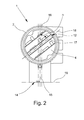
- FIG. 1 is a section through a part of a schematically illustrated inventive measuring device 1 and in the Fig. 2 a plan view is shown.
- the Fig. 3 provides a spatial view of a housing 2 of a measuring device 1.
- Another variant of a housing 2 as part of a measuring device 1 shows in a spatial representation of the Fig. 4 ,
- Fig. 1 is a part of a measuring device according to the invention 1 shown and that the housing 2, in which the electronic unit is located.
- the housing 2 In order to obtain a complete, functional measuring device 1, only a corresponding sensor unit is to be connected to the lower region of the housing 2, in which the respectively used measuring principle is implemented in order to preferably determine the process variable to be measured (eg flow or level) to gain an electrical parameter.
- the housing 2 In the housing 2 are here two electronic devices 3, 4, which are arranged one behind the other in the illustrated implementation of the invention.
- a guide structure can be seen on the wall, through which the electronic device 4 is more easily and safely introduced into the housing 2 during assembly and thus incorrect assembly or damage of individual parts can be prevented.
- the other electronic device 3 has, for example, a plurality of terminal contacts, which are arranged in the direction of the inner wall of the housing 2 and allow it by their partially multiple and in particular redundant configuration that, for example, a display or control unit can be placed and contacted with a selectable orientation.
- the contacting element 5 is arranged that is encapsulated in itself and in particular designed separately from the two electronic devices 3, 4.
- the contacting element 5 serves the electrical connection between the electronic devices 3, 4 and also the separation of the two electronic devices 3, 4, for example, to ensure intrinsic safety.
- connection transmission elements 6 are provided, which are realized here as pins in both directions.
- the transmission elements 6 are encapsulated or glazed within the outer wall 7, which is made of stainless steel here, of the contacting element 5, wherein care is taken for the intrinsic protection to the required distances between the individual transmission elements 6.
- the outer wall 7 is made of a plastic or of a composite material.
- the contacting element 5 is configured plug-shaped.
- the interior of the housing 2 is here divided into two chambers 8, 9, in each of which an electronic unit 3, 4 is located. Separately, the two chambers 8, 9 through a wall having a passage 10 which houses the contacting element 5.
- the passage 10 and the contacting element 5 are designed and matched to one another in such a way that the contacting element 5 is arranged in a precise fit in the passage 10.
- the respective sensor unit is attached, for. B. fixed by a screw.
- a bayonet closure By using, for example, a bayonet closure, however, a variant can be realized in which the sensor unit and the housing are partially against each other rotatable or pivotable.
- the lower neck allows, for example, the introduction of cables or z. B. flexible circuit boards, which emanate from the - not shown here - sensor unit and which are to be connected to the electronic devices 3, 4.
- the electronic devices 3, 4 and the contacting element 5 are introduced into the housing 2 and inserted into one another. If, in particular, the contacting element 5 and the respective electronic device 3, 4 connect with one another without a gap, the encapsulation of the contacting element 5 does not require any further encapsulation as in the prior art.
- the connection by plugging in particular is reversible, so that even when installed still individual components can be replaced, for example.
- Fig. 1 further threaded sleeves 11 can be seen, which are inserted into the housing 2, z. B. are pressed.
- These sleeves 11 are presently made of stainless steel and can be incorporated into a housing 2 made of aluminum or plastic, z. B. screw or press.
- the Fig. 2 allows a view of the electronics access 12 in the measuring device 1.
- the first longitudinal axis of this section extends in the illustrated variant perpendicular to the plane of the drawing.
- the electronics device 4 to be seen has a plurality of circuit boards or printed circuit boards, of which a circuit board 17 is located in a board plane 18. It can be seen that the other boards are also in planes parallel to the platinum level 18.
- a sensor access 14 is provided which serves the connection and contacting with a - not shown here - sensor unit.
- the end of the housing 2 opens into a connecting plane 19, on which the second longitudinal axis 15 of this portion of the housing 2 is perpendicular.
- an orientation plane 16 is spanned, which here also extends perpendicular to the plane of the drawing.
- other angles ⁇ are realized in other embodiments not shown here.
- the angle ⁇ differs from an integer multiple of 90 °, ie. H.
- the board plane 18 is arranged neither parallel to the orientation plane 16 nor perpendicular thereto.
- the circuit board 17 is also arranged at a 45 ° angle to the connection plane 19. Even with this relative orientation of the board 17 or circuit board to the connection plane 19 other angles are possible, each leading to an inclined position of the board 17.
- the housing 2 still has three further lateral accesses, for example for cable connections.
- the Fig. 3 shows a housing 2, in which the first longitudinal axis 13 of the electronics access 12 and the second longitudinal axis 15 of the sensor access 14 are located.
- the two longitudinal axes 13, 15 a right angle with each other and thus define an orientation plane, which can be considered in accordance with the symmetry plane of the housing 2 with respect to the two considered sections.
- the here indicated with respect to their position board 17 is visible relative to the plane formed by the two longitudinal axes 13, 14 inclined.
- Below the electronics access 12 is still the shape to recognize, which allows to attach a cover on a screw on the housing 2 and even attach a seal.
- the measuring device 1 of Fig. 4 consists of the housing 2 and the sensor unit 20. Both are connected to each other, for example via a screw.
- the sensor unit 20 shown concretely is only an example, and any other types of sensor units 20 for the different measuring principles can be connected to such a housing 2.
- Essential for the combination of the different component groups is that the sections coming into contact with each other are matched, so for example, for the connection between the housing 2 and sensor unit 20 to pay attention to matching neck geometries. If, in particular, a connection via a thread exists between housing 2 and sensor unit 20, the requirements of different explosion protection standards can also be met by way of a corresponding pitch or a corresponding number of threads between the two.
- the housing 2 is closed in the variant shown with a lid, through which a display and control element can be seen.
- a display and control element For the operation, for example, mechanical buttons are provided with a special film.
- Hall sensors are provided in the housing 2, which can be operated by means of magnetic pins by a closed lid and thus also comply with the explosion protection requirement.
- pins or sockets can be varied in the display unit or the associated electronic unit.
- the contacting takes place via cable, so that only the storage of the display or operating unit must allow different relative setting.
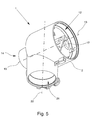
- the housing 2 of the measuring device 1 of the Fig. 5 fall the first longitudinal axis 13 of the electronics access 12 and the second longitudinal axis 15 of the sensor access 14 together, since in this variant both approaches 12, 14 are arranged in alignment one behind the other, wherein between the components of the measuring device 1 within the housing 2, a compound as in the Fig. 1 represented exists.
- a board 17 occasionally highlighted graphically to better recognize its orientation.
- the housing 2 additionally has an electrical connecting space 21 with a third longitudinal axis 22, which is arranged substantially perpendicular to the first 13 and second longitudinal axis 15.
- the third 22 and the first 13 and second longitudinal axis 15 span a plane to which the board plane of the board 17 is arranged at an angle different from an integer multiple of 90 °.
Landscapes
- Physics & Mathematics (AREA)
- General Physics & Mathematics (AREA)
- Arrangements For Transmission Of Measured Signals (AREA)
- Testing Or Calibration Of Command Recording Devices (AREA)
- Casings For Electric Apparatus (AREA)
- Keying Circuit Devices (AREA)
- Measuring Fluid Pressure (AREA)
Abstract
Description
- Die Erfindung betrifft ein Messgerät mit mindestens einem Gehäuse und mindestens zwei Elektronikeinrichtungen.
- Für die Realisierung einer in Bezug auf die Messprinzipien und auch auf die Dimensionierungen oder Schutzklassen usw. großen Bandbreite von unterschiedlichen Messgeräten werden gelegentlich sogenannte Baukästen oder Baukastensysteme verwendet. Dabei werden die betroffenen Messgeräte ähnlich konstruiert und möglichst aus untereinander austauschbaren Komponenten zusammengestellt. Dies hat zum einen den Vorteil eines einheitlichen und einen Wiedererkennungswert aufweisenden Aussehens. Zum anderen reduzieren sich dadurch die Kosten bei der Herstellung bzw. ergibt sich eine größere Flexibilität für die Anpassung der Messgeräte an konkrete Anforderungen. Hierfür werden die Messgeräte zumeist in einzelne miteinander kombinierbare Komponenten aufgeteilt, die selbst wiederum modular aufgebaut sein können.
- Bei Messgeräten ist dabei eine mögliche Trennung diejenige zwischen einer Sensoreinheit, in der das Messprinzip für die eigentliche Messung der Prozessgröße realisiert ist, und einer Elektronikeinheit, die der Auswertung oder Verarbeitung des Roh- oder Messwertes dient, den die Sensoreinheit erzeugt. Dabei kann die Sensoreinheit ggf. auch über eigene Elektronikkomponenten verfügen, die der Messung oder der Aus- bzw. Umwandlung der Rohwerte dienen. Sowohl die Sensor- als auch die Elektronikeinheit sind dabei üblicherweise in einem jeweiligen Gehäuse angeordnet, wobei das Gehäuse der Sensoreinheit ggf. eine Öffnung für einen direkten Kontakt mit dem zu messenden Messmedium und das Gehäuse der Elektronikeinheit wenigstens eine Öffnung für eine Energieversorgung bzw. eine Übermittlung der Messwerte z. B. an eine übergeordnete Einheit aufweisen. Weiterhin sind die beiden Gehäuse üblicherweise derartig ausgestaltet, dass sie sich miteinander verbinden lassen und dass es auch zu einer Energie- bzw. Signalübertragung zwischen der Sensor- und der Elektronikeinheit kommen kann.
- Eine Elektronikeinheit lässt sich weiterhin in mehrere Module aufteilen, die ggf. auch beliebig miteinander austauschbar oder kombinierbar sind. Unterteilungen sind dabei möglich in eine zentrale Einheit, die der Energieversorgung, der Steuerung, der Messung und der Verarbeitung der Signale der Sensoreinheit in Ausgebesignale dient, in eine Anschluss- oder Konvertereinheit, die dem Anschluss des Messgerätes dient, und in ggf. an eine Anzeige- oder Bedieneinheit, die der Anzeige der Messwerte bzw. dem Bedienen des Messgerätes vor Ort dient.
- Je nach Grad der Modularisierung können beliebige Anschlüsse für unterschiedliche Bussysteme mit beliebigen Anzeigeeinheiten und unterschiedlichen Sensortypen kombiniert werden. Eine modulare Ausgestaltung der Elektronikeinheit wird beispielsweise gezeigt in den Offenlegungsschrift
DE 10 2006 009 827 A1 oderDE 10 2009 054 649 A1 oder in der PatentschriftDE 197 82 057 B4 . Die OffenlegungsschriftDE 101 26 654 A1 beschreibt ein Gehäuse eines Messgerätes mit einem Anzeige- und einem davon separaten Anschlussraum für die Aufnahme eines Anzeige- bzw. eines Anschlussmoduls. Einen ähnlichen Aufbau offenbart die PatentschriftEP 0 775 292 B1 mit einem Gehäuse, das über zwei durch eine Wand mit einem Durchbruch getrennte Räume verfügt. Die Elektronikkomponenten in den Räumen sind durch Signalstifte miteinander kontaktiert, die in dem Durchbruch vergossen angeordnet sind. In der GebrauchsmusterschriftDE 203 14 618 U1 befindet sich eine Stiftleiste vergossen innerhalb eines Durchführungsraums zwischen zwei Teilräumen des Gehäuses. Eine weitere Ausgestaltung eines Gehäuses und der darin befindlichen modularen Elektronikkomponenten nennt das DokumentWO 2011/160949 A1 . Steckkontakte innerhalb eines vergossenen Messgerätes, die direkt an eine Elektronikkomponente anschließen und der Verbindung zu anderen Elektronikelementen dienen, offenbart beispielsweise die OffenlegungsschriftDE 102 33 296 A1 . - In vielen Anwendungen wird von den Messgeräten Eigensicherheit gefordert. Die Zündschutzart "Eigensicherheit" beruht insbesondere auf einer Begrenzung der elektrischen Energie innerhalb der Elektronik des Messgerätes bzw. innerhalb von Abschnitten davon und der elektrischen Energie von Verbindungsleitungen auf ein Niveau unterhalb des Niveaus, bei dem im Kontakt mit einer explosionsfähigen Atmosphäre eine Zündung hervorgerufen werden kann. Eine wesentliche Anforderung, die sich aus den relevanten Normen ergibt, ist dabei die Einhaltung von Trennabständen zwischen leitfähigen Komponenten. Der Trennabstand ist dabei der kürzeste Abstand zwischen zwei solchen Komponenten. Unterschieden wird nach der Art des Mediums, durch das der Weg des kürzesten Abstandes führt, so dass sich unterschiedliche Trennabstände für Luftstrecken, Abstände im Verguss, Abstände durch feste Isolierung, Kriechstrecken in Luft oder Kriechstrecken unter einer Schutzschicht ergeben. Zudem hängen die einzuhaltenden Trennabstände von den maximal auftretenden Spannungen zwischen den leitfähigen Komponenten ab.
- Details zur Ausgestaltung von modularen Elektronikkomponenten und deren Gehäusen für einen möglichen Einsatz in einem Baukasten für Messgeräte finden sich ebenfalls im Stand der Technik. So beschreibt die Offenlegungsschrift
DE 10 2010 033 470 A1 ein Bedienfeld für Messgeräte und die OffenlegungsschriftDE 41 09 475 A1 ein drehbares Display. Eine drehbare mechanische Verbindung zwischen der Sensoreinheit und dem Gehäuse der Elektronikeinheit zeigt die OffenlegungsschriftDE 10 2004 044 890 A1 . Eine wechselbare Verbindung zwischen der Sensoreinheit über eine Art Stecker mit einem Feldbus oder alternativ mit einem Programmiergerät ist der OffenlegungsschriftDE 103 27 013 A1 zu entnehmen. Weitere Einzelheiten wie das erleichterte Einführen eines Kabels in ein Gehäuse (z. B. die PatentschriftDE 10 2007 036 484 B3 ), das Erzeugen eines hartmetallischen Gewindes innerhalb eines Aluminiumgehäuses (z. B. die PatentschriftUS 3,462,539 ), das Umgeben von Anschlussdrähten in einem Gerät mit Keramik- oder Glashülsen (z. B. die GebrauchsmusterschriftDE 20 2010 007 043 U1 ), das Fixieren von Elektronikbauteilen über konische Schrägen im Gehäuse (z. B. die OffenlegungsschriftDE 10 2005 024 259 A1 ) oder besondere Vorrichtungen an der Außenseite des Gehäuses für Plombierungen (z. B. die OffenlegungsschriftDE 10 2010 003 743 A1 ) lassen sich ebenfalls schon im Stand der Technik finden und können zur Ausgestaltung von Messgeräten und deren Gehäusen beitragen. - Der Erfindung liegt die Aufgabe zugrunde, ein Messgerät vorzuschlagen, dessen Elektronik modular aufgebaut ist und eine einfache Anpassung an den Eigenschutz erlaubt.
- Die aufgezeigte Aufgabe ist erfindungsgemäß zunächst und im Wesentlichen bei dem in Rede stehenden Messgerät dadurch gelöst, dass mindestens ein verkapseltes Kontaktierungselement vorgesehen ist. Das Kontaktierungselement ist dabei von den Elektronikeinrichtungen und dem Gehäuse separat ausgestaltet und zwischen den zwei Elektronikeinrichtungen angeordnet. Weiterhin weist das Kontaktierungselement mindestens ein elektronisches Übertragungselement zur Erzeugung einer elektrischen Verbindung zwischen den zwei Elektronikeinrichtungen auf.
- Im Stand der Technik ist es bekannt, dass sich Elektronikeinrichtungen in durch eine Wand getrennten Kammern eines Gehäuses befinden und dass die Elektronikeinrichtungen durch Übertragungselemente wie z. B. Kontaktstifte miteinander kontaktiert werden, die in einem Durchbruch der Wand angeordnet und dort vergossen sind. D. h. ein solches Kontaktierungselement ist quasi Bestandteil der Wand des Gehäuses. Weiterhin ist es bekannt, dass einzelne Elektronikeinrichtungen über entsprechende Übertragungselemente verfügen und dass für den Explosionsschutz die gesamte Elektronikeinheit vergossen wird. Im erfindungsgemäßen Messgerät ist jedoch ein separates Kontaktierungselement als eigenständiges Bauteil vorgesehen, das insbesondere bereits verkapselt ist - also an sich und für sich selbst verkapselt ist - und nicht erst innerhalb des Gehäuses verkapselt werden muss wie im Stand der Technik.
- Ein solches bereits fertig einsetzbares Kontaktierungselement erlaubt neben der vereinfachten Anwendbarkeit auch die leichtere Anpassung an die verwendeten Gehäuse bzw. die Ausführungen der Elektroneinrichtungen. So kann der Abstand zwischen den Elektronikeinrichtungen leicht durch die Höhe des jeweils zwischen ihnen verwendeten Kontaktierungselements eingestellt werden. Da das Kontaktierungselement bereits verkapselt ist und es einer Verkapselung im Gehäuse nicht bedarf, lassen sich beim erfindungsgemäßen Messgerät auch defekte Komponenten leichter austauschen, da im einfachsten Fall nur die Steckverbindung zwischen einer Elektronikeinrichtung und dem Kontaktierungselement aufgehoben werden muss. Auch können relativ einfach unterschiedliche Anordnungen von mehreren Übertragungselementen, die ggf. auch komplexere Strukturen aufweisen, erzeugt werden, ohne dass es beispielsweise einer Abstützung im Gehäuse vor dem Vergießen wie im Stand der Technik bedürfte.
- Weiterhin kann so auch eine abgewinkelte Anordnung der Elektronikeinrichtungen realisiert werden, indem das Kontaktierungselement einen passenden Winkel aufweist. Auch die Kontaktierung von mehr als zwei Elektronikeinrichtungen lässt sich realisieren, indem das Kontaktierungselement mehrere Übertragungselemente in unterschiedlichen Raumwinkeln aufweist. Da das Kontaktierungselement separat und bereits verkapselt ist, kann es als Teil eines Baukastensystem die Kombination von unterschiedlichen Elektronikeinrichtungen bzw. Gehäusen deutlich vereinfachen. Ein solches erfindungsgemäßes Messgerät ist dabei beispielsweise mit unterschiedlichen Sensoreinheiten verbunden, die z. B. der Durchflussmessung, der Füllstandsmessung, der pH-Wert- oder der Sauerstoffgehaltmessung dienen und beispielsweise als Coriolis-, als MID- oder als Radarfüllstandmessgerät gegeben sind.
- In einer Ausgestaltung ist vorgesehen, dass das Übertragungselement ein Kontaktierungsstift ist. Vorzugsweise sind mehrere Übertragungselemente vorgesehen, die alle oder teilweise als Kontaktierungsstifte ausgestaltet sind. Durch solche Kontaktierungsstifte ist die Verbindung zwischen den Elektronikeinrichtungen einfach zu realisieren, indem dort die passenden Buchsen vorgesehen sind. In einer Ausgestaltung weist das Kontaktierungselement an beiden den Elektronikeinrichtungen zugewandten Seiten Kontaktierungsstifte auf bzw. es liegen durchgehende Kontaktierungsstifte vor. Alternativ weist das Kontaktierungselement an einer Seite Kontaktierungsstifte und an der anderen Seite Buchsen auf. Es sind auch beliebige Kombinationen mit anderen Übertragungselementen, wie z. B. Steckern oder Kabeln möglich.
- In einer weiteren Variante ist das Übertragungselement innerhalb einer Außenwandung des Kontaktierungselements vergossen und/oder eingeglast. Diese Verkapselung bzw. das Einglasen dient dabei insbesondere der Einstellung der für die Zündschutzart erforderlichen minimalen Abstände zwischen den stromführenden Leitern bzw. Kontaktierungselementen. In einer Ausgestaltung sind insbesondere mehrere Übertragungselemente vorgesehen, die alle innerhalb der Außenwandung des Kontaktierungselements vergossen und/oder eingeglast sind. Die Außenwandung als Teil der äußeren Hülle des Kontaktierungselements kann dabei zumindest teilweise aus Edelstahl oder einem Kunststoff bestehen. In einer Variante ist das Kontaktierungselement im Wesentlichen stopfen- oder pfropfenförmig ausgestaltet. Der Grundquerschnitt ist dabei insbesondere vorzugsweise kreisförmig, wobei jedoch keine Beschränkung auf diese Form besteht. In einer weiteren Ausgestaltung ist der Querschnitt des Kontaktierungselements asymmetrisch, so dass das Kontaktierungselement nur in einer definierten Orientierung in das Gehäuse einsetzbar ist, was automatisch zu definierten Einbau- und Kontaktierungspositionen - auch der verbundenen Elektronikeinrichtungen - führt.
- Vorteilhafterweise sind das Kontaktierungselement und die zwei Elektronikeinrichtungen derartig ausgestaltet und aufeinander abgestimmt, dass das Kontaktierungselement und die zwei Elektronikeinrichtungen im Wesentlichen spaltfrei miteinander verbunden sind. Die Abmessungen der Elektronikeinrichtungen bzw. deren Gehäuse und des Kontaktierungselements sind daher derart, dass sie nach einer Verbindung untereinander spaltfrei sind. Vorzugsweise geschieht dies ohne zusätzliche Dicht- oder Vergusselemente. Für die Erhöhung der Sicherheit ist jedoch ein zusätzlicher Verguss bzw. sind zusätzliche Dichtelemente um das Kontaktierungselement bzw. die zwei Elektronikeinrichtungen herum möglich.
- In einer vorteilhaften Ausgestaltung weist das Gehäuse mindestens zwei Kammern auf, zwischen denen ein Durchgang besteht. Dabei ist in jeder Kammer eine der zwei Elektronikeinrichtungen und das Kontaktierungselement in dem Durchgang angeordnet. Das Kontaktierungselement ist dabei im erfindungsgemäßen Messgerät bereits verkapselt und entsteht nicht - wie im Stand der Technik - erst durch das Vergießen von beispielweise Kontaktstiften, die durch einen solchen Durchgang hindurchgeführt sind. In einer Ausgestaltung ist das Kontaktierungselement passgenau in dem Durchgang angeordnet.
- In weiteren Ausgestaltungen wird die Trennung zwischen den zwei Elektronikeinrichtungen bzw. zwischen den zwei Kammern verstärkt. Dabei ist in einer Ausgestaltung vorgesehen, dass das Kontaktierungselement im Durchgang zusätzlich zu seiner Verkapselung vergossen ist. Alternativ oder ergänzend ist vorgesehen, dass der Übergang zwischen mindestens einer Elektronikeinrichtung und dem Kontaktierungselement vergossen ist. Zusätzlich ist ebenfalls ergänzend oder alternativ zwischen mindestens einer Elektronikeinrichtung und dem Kontaktierungselement und/oder zwischen dem Kontaktierungselement und dem Durchgang mindestens eine Dichteinrichtung - insbesondere ein O-Ring - angeordnet. Alternativ kann auch der gesamte Innenraum des Gehäuses vergossen sein.
- In einer Ausgestaltung wird insbesondere darauf eingegangen, dass Messgeräte in der Anwendung z. B. als Teil der Prozessautomatisierung manchmal starken mechanischen Belastungen ausgesetzt sind. Ist ein Messgerät beispielsweise an einem Behälter - ein Silo oder Tank - eines Mediums mit der Sensoreinheit angebracht, so kann das Befüllen des Behälters oder ein Rührwerk im Behälter zu Erschütterungen des Messgerätes und dadurch auch zu einer Belastung der elektronischen Bauteile bzw. der Kontaktierungen im Messgerät führen. Entsprechendes gilt, wenn das Messgerät an einem Rohr z. B. für die Messung des Durchflusses angebracht ist. Um die Auswirkungen solcher Schwingungen auf die Elektronikkomponenten herabzusetzen, ist die folgende Ausgestaltung vorgesehen, die jedoch auch unabhängig von der obigen Art der Ausgestaltung des Kontaktierungselements ist, gleichwohl aber eine sehr gute Kombination damit bildet, um ein möglichst optimales Messgerät zu realisieren.
- Die Ausgestaltung besteht darin, dass das Gehäuse mindestens einen Elektronikzugang zu mindestens einer der zwei Elektronikeinrichtungen aufweist. Das Gehäuse verfügt daher über einen Zugang oder eine Öffnung, über die mindestens eine Elektronikeinrichtung erreichbar, insbesondere einbringbar ist. Durch den Elektronikzugang erstreckt sich insbesondere eine erste Längsachse. Ist beispielsweise der Abschnitt des Gehäuses, der sich an den Elektronikzugang anschließt und der vorzugsweise eine Elektronikeinrichtung umfasst, im Wesentlichen zylinderförmig - beispielweise mit einer kreisförmigen Grundfläche - ausgestaltet, so ist besagte erste Längsachse die Längsachse dieses zylindrischen Abschnitts. Mündet der Elektronikzugang allgemein auf eine Zugangsebene, d. h. schließt das Gehäuse in einer solchen Zugangsebene ab, so ist die erste Längsachse insbesondere die Normale auf dieser Zugangsebene, die sich mittig durch den Elektronikzugang erstreckt. Weiterhin verfügt das Gehäuse über einen Sensorzugang zur Anbindung einer Sensoreinheit. Die Sensoreinheit dient dabei der eigentlichen Messung oder Überwachung beispielsweise einer Prozessgröße wie Füllstand oder Durchfluss und liefert zumeist Rohwerte, die aus einer für die Messung bzw. Überwachung verwendeten Abhängigkeit einer messbaren Größe von der Prozessgröße entstehen. Für den Anschluss einer solchen Sensoreinheit an das Gehäuse ist ein Sensorzugang, also eine Öffnung für die Sensoreinheit vorgesehen. Dabei mündet der Sensorzugang in eine Anschlussebene. Da in vielen Anwendungen die Anbindung des Messgerätes an einen Behälter oder an ein Rohr usw. über einen Flansch geschieht, lässt sich eine solche Anschlussebene auch als Flanschebene bezeichnen. Durch den Sensorzugang erstreckt sich insbesondere eine zweite Längsachse. Ist auch dieser Abschnitt des Gehäuses, der sich an den Sensorzugang anschließt und der ggf. auch für die Kontaktierung mit der Sensoreinheit ausgestaltet ist, im Wesentlichen zylindrisch - ggf. ebenfalls mit einer kreisförmigen Grundfläche - ausgestaltet, so ist auch die zweite Längsachse die Längsachse dieses zylindrischen, dem Übergang zur Sensoreinheit dienenden Teils des Gehäuses. Die zweite Längsachse steht dabei insbesondere senkrecht auf der Anschlussebene.
- In einer besonderen Ausgestaltung stehen die erste Längsachse und die zweite Längsachse senkrecht aufeinander, so dass das Gehäuse zumindest teilweise L- oder T-förmig ausgestaltet ist. Der Winkel zwischen der ersten und der zweiten Längsachse kann jedoch auch einen anderen Wert haben, so dass sich ggf. eine Y-Form ergibt, falls noch zumindest ein dritter Abschnitt im Gehäuse vorgesehen ist. In einer weiteren beispielhaften Ausgestaltung sind die Zugangsebene und die Anschlussebene abweichend zu einer parallelen Anordnung zueinander angeordnet. Die erste und die zweite Längsachse spannen insbesondere eine Orientierungsebene auf, die insbesondere senkrecht auf der Zugangs- und der Anschlussebene steht.
- Weiterhin weist mindestens eine Elektronikeinrichtung mindestens eine Platine auf. Platinen werden zumeist zum Tragen der jeweiligen Elektronikbauteile verwendet. Die Platine liegt dabei im Wesentlichen in einer Platinenebene. Die Platine ist derartig im Gehäuse angeordnet, dass die Platinenebene in einem Winkel zur Orientierungsebene angeordnet ist, der sich von einem ganzzahligen Vielfachen von 90° unterscheidet. Handelt es sich bei dem Elektronikzugang um eine kreisförmige Öffnung und dient die Anschlussebene als Vorgabe eines gedachten Südpols, so ist die Platine in dieser Ausgestaltung weder in Nord-Süd- noch ein Ost-West-Richtung ausgerichtet. In einer Ausgestaltung ist die Platinenebene entlang den Winkelhalbierenden der Quadranten, also in Nordost-/Südwest- oder in Nordwest-/Südost-Richtung angeordnet. In einer weiteren Ausgestaltung ist zudem die Platinenebene in einem Winkel zur Anschlussebene angeordnet, der sich ebenfalls von einem ganzzahligen Vielfachen von 90° unterscheidet. Die Platinenebene ist daher vorzugsweise in dieser Ausgestaltung weder senkrecht zur Anschlussebene noch parallel dazu angeordnet. In einer weiteren Ausgestaltung ist die Platinenebene vorzugsweise in einem 45°-Winkel zur Anschlussebene angeordnet. Durch eine solche "schräge" Anordnung der Platine relativ zur Ebene des Anschlusses wird die bei Erschütterungen auf die Platine und deren Bestandteile wirkende Kraft vermindert, insbesondere durch die vektorielle Aufteilung wirkender Kräfte in die Platinenebene.
- Im Einzelnen gibt es eine Vielzahl von Möglichkeiten, das erfindungsgemäße Messgerät auszugestalten und weiterzubilden. Dazu wird verwiesen einerseits auf die dem Patentanspruch 1 nachgeordneten Patentansprüche, andererseits auf die folgende Beschreibung von Ausführungsbeispielen in Verbindung mit der Zeichnung. In der Zeichnung zeigen
- Fig. 1
- eine schematische, im Wesentlichen die grundlegende Anordnung verdeutlichende Darstellung eines Teils eines Messgerätes im Schnitt,
- Fig. 2
- eine Draufsicht auf das Messgerät der
Fig. 1 , - Fig. 3
- eine räumliche Darstellung eines Gehäuses eines Messgerätes,
- Fig. 4
- eine räumliche Darstellung eines Messgerätes und
- Fig. 5
- eine räumliche Darstellung einer weiteren Variante des Gehäuses eines Messgerätes.
- In der
Fig. 1 ist ein Schnitt durch einen Teil eines schematisch dargestellten erfindungsgemäßen Messgerätes 1 und in derFig. 2 eine Draufsicht darauf dargestellt. DieFig. 3 bietet einen räumlichen Blick auf ein Gehäuse 2 eines Messgeräts 1. Eine andere Variante eines Gehäuses 2 als Teil eines Messgerätes 1 zeigt in räumlicher Darstellung dieFig. 4 . - In der
Fig. 1 ist ein Teil eines erfindungsgemäßen Messgerätes 1 dargestellt und zwar das Gehäuse 2, in dem sich die Elektronikeinheit befindet. Um ein vollständiges, funktionsfähiges Messgerät 1 zu erhalten, ist an den unteren Bereich des Gehäuses 2 lediglich noch eine entsprechende Sensoreinheit anzuschließen, in der das jeweils verwendete Messprinzip umgesetzt wird, um aus der zu messenden Prozessgröße (z. B. Durchfluss oder Füllstand) vorzugsweise eine elektrische Messgröße zu gewinnen. In dem Gehäuse 2 befinden sich hier zwei Elektronikeinrichtungen 3, 4, die in der dargestellten Umsetzung der Erfindung hintereinander angeordnet sind. Bei der größeren Elektronikeinrichtung 4 ist an der Wandung eine Führungsstruktur zu erkennen, durch die die Elektronikeinrichtung 4 leichter und sicher in das Gehäuse 2 bei der Montage eingebracht und wodurch eine Fehlmontage oder eine Beschädigung von Einzelteilen verhindert werden kann. Hierzu gehört auch, dass die Elektronikeinrichtung 4 bzw. die Innenwand des Gehäuses 2 konisch ausgestaltet sind. Die andere Elektronikeinrichtung 3 verfügt beispielsweise über mehrere Klemmenkontakte, die in Richtung der Innenwand des Gehäuses 2 angeordnet sind und es durch ihre teilweise mehrfache und insbesondere redundante Ausgestaltung erlauben, dass beispielsweise eine Anzeige- oder Bedieneinheit mit einer wählbaren Orientierung aufgesetzt und kontaktiert werden kann. - Zwischen den zwei Elektronikeinrichtungen 3, 4 ist das Kontaktierungselement 5 angeordnet, dass in sich gekapselt und insbesondere separat von den zwei Elektronikeinrichtungen 3, 4 ausgestaltet ist. Das Kontaktierungselement 5 dient dabei der elektrischen Verbindung zwischen den Elektronikeinrichtungen 3, 4 und auch der Trennung beider Elektronikeinrichtungen 3, 4, beispielsweise für die Gewährleistung der Eigensicherheit.
- Für die Verbindung sind Übertragungselemente 6 vorgesehen, die hier in beide Richtungen als Stifte realisiert sind. Die Übertragungselemente 6 sind dabei innerhalb der Außenwandung 7, die hier aus Edelstahl besteht, des Kontaktierungselements 5 vergossen bzw. eingeglast, wobei für den Eigenschutz auf die erforderlichen Abstände zwischen den einzelnen Übertragungselementen 6 geachtet ist. In einer alternativen Ausgestaltung besteht die Außenwandung 7 aus einem Kunststoff bzw. aus einem Verbundwerkstoff. In der hier gezeigten Ausführung ist das Kontaktierungselement 5 stopfenförmig ausgestaltet.
- Der Innenraum des Gehäuses 2 ist hier in zwei Kammern 8, 9 unterteilt, in denen sich jeweils eine Elektronikeinheit 3, 4 befindet. Getrennt sind die zwei Kammern 8, 9 durch eine Wand, die einen Durchgang 10 aufweist, der das Kontaktierungselement 5 beherbergt. Vorliegend sind der Durchgang 10 und das Kontaktierungselement 5 derartig ausgestaltet und aufeinander abgestimmt, dass das Kontaktierungselement 5 passgenau im Durchgang 10 angeordnet ist.
- Am hier nach unten ragenden Hals des Gehäuses 2 wird insbesondere die jeweilige Sensoreinheit angebracht, z. B. durch eine Schraube fixiert. Durch die Anwendung von beispielsweise einem Bajonettverschluss kann jedoch auch eine Variante realisiert werden, in der die Sensoreinheit und das Gehäuse teilweise gegeneinander dreh- bzw. schwenkbar sind. Der untere Hals erlaubt beispielsweise auch das Einbringen von Kabeln oder z. B. flexiblen Leiterplatten, die von der - hier nicht dargestellten - Sensoreinheit ausgehen und die mit den Elektronikeinrichtungen 3, 4 zu verbinden sind.
- Bei einer Montage eines erfindungsgemäßen Messgerätes 1 werden die Elektronikeinrichtungen 3, 4 und das Kontaktierungselement 5 in das Gehäuse 2 eingebracht und ineinander gesteckt. Verbinden sich dabei insbesondere das Kontaktierungselement 5 und die jeweilige Elektronikeinrichtung 3, 4 spaltfrei miteinander, so ist durch die Verkapselung des Kontaktierungselements 5 kein weiterer Verguss wie im Stand der Technik erforderlich. Die Verbindung durch das Stecken ist insbesondere reversibel, so dass auch im eingebauten Zustand noch einzelne Komponenten beispielsweise ausgetauscht werden können.
- In der
Fig. 1 sind weiterhin Gewindehülsen 11 zu erkennen, die in das Gehäuse 2 eingefügt, z. B. eingepresst sind. Diese Hülsen 11 sind vorliegend aus Edelstahl und lassen sich in ein Gehäuse 2 aus Aluminium oder Kunststoff einbringen, z. B. eindrehen oder einpressen. - Die
Fig. 2 erlaubt einen Blick über den Elektronikzugang 12 in das Messgerät 1. Die erste Längsachse dieses Abschnitts erstreckt sich dabei bei der dargestellten Variante senkrecht in die Zeichnungsebene hinein. Die zu sehende Elektronikeinrichtung 4 weist mehrere Platinen oder Leiterplatten auf, von denen eine Platine 17 sich in einer Platinenebene 18 befindet. Dabei ist zu erkennen, dass sich auch die anderen Platinen in Ebenen parallel der Platinenebene 18 befinden. Am unteren Hals des Gehäuses 2 ist ein Sensorzugang 14 vorgesehen, der der Verbindung und Kontaktierung mit einer - hier nicht dargestellten - Sensoreinheit dient. Das Ende des Gehäuses 2 mündet dabei in einer Anschlussebene 19, auf der die zweite Längsachse 15 dieses Abschnitts des Gehäuses 2 senkrecht steht. - Von der ersten Längsachse und der zweiten Längsachse 15 wird eine Orientierungsebene 16 aufgespannt, die hier ebenfalls senkrecht zur Zeichnungsebene verläuft. Wie zu erkennen, ist die Platinenebene 18 in einem Winkel α = 45° gegenüber der Orientierungsebene 16 geneigt. Dabei sind jedoch auch andere Winkel α, in anderen hier nicht dargestellten Ausgestaltungen realisiert. Gemein ist allen Varianten, dass der Winkel α, sich von einem ganzzahligen Vielfachen von 90° unterscheidet, d. h. die Platinenebene 18 ist weder parallel zur Orientierungsebene 16 noch senkrecht dazu angeordnet. Die Platine 17 ist weiterhin auch in einem 45°-Winkel zur Anschlussebene 19 angeordnet. Auch bei dieser relativen Orientierung der Platine 17 oder Leiterplatte zur Anschlussebene 19 sind andere Winkel möglich, die jeweils zu einer Schräglage der Platine 17 führen. Diese Neigung gegenüber der Anschlussebene 19, über die zumeist die Anbringung des Messgerätes 1 an einem Behälter oder einem Rohr erfolgt, werden die Auswirkungen von Erschütterungen auf die Platine 17 bzw. deren Bauteile oder der Kontaktierungen der Bauteile reduziert.
- In der dargestellten Variante ist weiterhin zu erkennen, dass das Gehäuse 2 noch drei weitere seitliche Zugänge beispielsweise für Kabelverbindungen aufweist.
- Die
Fig. 3 zeigt ein Gehäuse 2, in dem die erste Längsachse 13 des Elektronikzugangs 12 und die zweite Längsachse 15 des Sensorzugangs 14 eingezeichnet sind. In der dargestellten Variante bilden die beiden Längsachsen 13, 15 einen rechten Winkel miteinander und definieren folglich eine Orientierungsebene, die entsprechend als Symmetrieebene des Gehäuses 2 in Bezug auf die beiden betrachteten Abschnitte aufgefasst werden kann. Die hier bezüglich ihrer Lage angedeutete Platine 17 ist sichtbar gegenüber der von den beiden Längsachsen 13, 14 gebildeten Ebene geneigt. Unterhalb des Elektronikzugangs 12 ist noch die Ausformung zu erkennen, die es erlaubt, einen Deckel über eine Schraube am Gehäuse 2 zu befestigen und sogar eine Plombierung anzubringen. - Das Messgerät 1 der
Fig. 4 besteht aus dem Gehäuse 2 und der Sensoreinheit 20. Beide sind beispielsweise über eine Verschraubung miteinander verbunden. Die konkret gezeigte Sensoreinheit 20 ist dabei nur ein Beispiel, und es lassen sich beliebige andere Arten von Sensoreinheiten 20 für die unterschiedlichen Messprinzipien an ein solches Gehäuse 2 anschließen. Wesentlich für die Kombination der unterschiedlichen Bauteilegruppen ist, dass die miteinander in Kontakt tretenden Abschnitte aufeinander abgestimmt sind, so ist beispielsweise für die Verbindung zwischen Gehäuse 2 und Sensoreinheit 20 auf passende Halsgeometrien zu achten. Besteht insbesondere zwischen Gehäuse 2 und Sensoreinheit 20 eine Verbindung über ein Gewinde, so kann über eine entsprechende Steigung bzw. eine entsprechende Anzahl von Gewindegängen zwischen beiden auch den Forderungen unterschiedlicher Explosionsschutznormen entsprochen werden. - Das Gehäuse 2 ist in der gezeigten Variante mit einem Deckel verschlossen, durch den hindurch ein Anzeige- und Bedienelement zu sehen ist. Für die Bedienung sind beispielsweise mechanische Tasten mit einer speziellen Folie vorgesehen. Alternativ lässt sich jedoch auch eine kapazitive oder induktive Tastatur realisieren, die auf die Näherung eines Fingers oder eines Stiftes reagiert. In einer weiteren Variante sind Hallsensoren im Gehäuse 2 vorgesehen, die mittels Magnetstiften durch einen geschlossenen Deckel bedient werden können und dadurch auch der Explosionsschutzanforderung entsprechen. Werden zwischen einem Display-Modul und der dahinterliegenden Elektroneinrichtung Kontaktstifte verwendet, so ist auch das Befestigen des Display-Moduls vereinfacht und es kann ggf. auch ein Drehen der Anzeigeeinheit gegenüber dem Gehäuse 2 einfach umgesetzt werden, indem beispielsweise die Anzahl der Kontaktstifte erhöht und die Kontaktstifte unter unterschiedlichen Raumwinkeln redundant ausgeführt werden. Dabei können bei der Anzeigeeinheit bzw. der zugeordneten Elektronikeinheit auch Stifte oder Buchsen variiert werden. Alternativ erfolgt die Kontaktierung über Kabel, so dass lediglich die Lagerung der Anzeige- bzw. Bedieneinheit unterschiedliche relative Einstellung erlauben muss.
- Im Gehäuse 2 des Messgeräts 1 der
Fig. 5 fallen die erste Längsachse 13 des Elektronikzugangs 12 und die zweite Längsachse 15 des Sensorzugangs 14 zusammen, da in dieser Variante beide Zugänge 12, 14 fluchtend hintereinander angeordnet sind, wobei zwischen den Komponenten des Messgerätes 1 innerhalb des Gehäuses 2 eine Verbindung wie in derFig. 1 dargestellt besteht. Von einer Elektronikeinrichtung ist hier eine Platine 17 vereinzelt zeichnerisch hervorgehoben, um dessen Orientierung besser zu erkennen. Das Gehäuse 2 verfügt zusätzlich über einen elektrischen Anschlussraum 21 mit einer dritten Längsachse 22, die im Wesentlichen senkrecht auf der ersten 13 bzw. zweiten Längsachse 15 angeordnet ist. Die dritte 22 und die erste 13 bzw. zweite Längsachse 15 spannen eine Ebene auf, zu der die Platinenebene der Platine 17 in einem Winkel unterschiedlich zu einem ganzzahligen Vielfachen von 90° angeordnet ist.
Claims (10)
- Messgerät (1), mit mindestens einem Gehäuse (2) und mit mindestens zwei Elektronikeinrichtungen (3, 4),
dadurch gekennzeichnet,
dass mindestens ein verkapseltes Kontaktierungselement (5) vorgesehen ist, dass das Kontaktierungselement (5) von den Elektronikeinrichtungen (3, 4) und dem Gehäuse (2) separat ausgestaltet ist, dass das Kontaktierungselement (5) zwischen den zwei Elektronikeinrichtungen (3, 4) angeordnet ist, und dass das Kontaktierungselement (5) mindestens ein elektronisches Übertragungselement (6) zur Erzeugung einer elektrischen Verbindung zwischen den zwei Elektronikeinrichtungen (3, 4) aufweist. - Messgerät (1) nach Anspruch 1, dadurch gekennzeichnet, dass das Übertragungselement (6) ein Kontaktierungsstift ist.
- Messgerät (1) nach Anspruch 1 oder 2, dadurch gekennzeichnet, dass das Übertragungselement (6) innerhalb einer Außenwandung (7) des Kontaktierungselements (5) vergossen und/oder eingeglast ist.
- Messgerät (1) nach Anspruch 3, dadurch gekennzeichnet, dass die Außenwandung (7) zumindest teilweise aus Edelstahl oder einem Kunststoff besteht.
- Messgerät (1) nach einem der Ansprüche 1 bis 4, dadurch gekennzeichnet, dass das Kontaktierungselement (5) im Wesentlichen stopfenförmig ausgestaltet ist.
- Messgerät (1) nach einem der Ansprüche 1 bis 5, dadurch gekennzeichnet, dass das Kontaktierungselement (5) und die zwei Elektronikeinrichtungen (3, 4) derartig ausgestaltet und aufeinander abgestimmt sind, dass das Kontaktierungselement (5) und die zwei Elektronikeinrichtungen (3, 4) im Wesentlichen spaltfrei miteinander verbunden sind.
- Messgerät (1) nach einem der Ansprüche 1 bis 6, dadurch gekennzeichnet, dass das Gehäuse (2) mindestens zwei Kammern (8, 9) aufweist, zwischen denen ein Durchgang (10) besteht, dass in jeder Kammer (8, 9) eine der zwei Elektronikeinrichtungen (3, 4) angeordnet ist, und dass das Kontaktierungselement (5) in dem Durchgang (10) angeordnet ist.
- Messgerät (1) nach Anspruch 7, dadurch gekennzeichnet, dass das Kontaktierungselement (5) im Durchgang (10) vergossen ist, und/oder dass der Übergang zwischen mindestens einer Elektronikeinrichtung (3, 4) und dem Kontaktierungselement (5) vergossen ist, und/oder dass zwischen mindestens einer Elektronikeinrichtung (3, 4) und dem Kontaktierungselement (5) und/oder zwischen dem Kontaktierungselement (5) und dem Durchgang (10) mindestens eine Dichteinrichtung - insbesondere ein O-Ring - angeordnet ist.
- Messgerät (1) nach einem der Ansprüche 1 bis 8, dadurch gekennzeichnet, dass das Gehäuse (2) mindestens einen Elektronikzugang (12) zu mindestens einem der zwei Elektronikeinrichtungen (3, 4) aufweist, wobei sich durch den Elektronikzugang (12) eine erste Längsachse (13) erstreckt, dass das Gehäuse (2) einen Sensorzugang (14) zur Anbindung einer Sensoreinheit (20) aufweist, wobei sich durch den Sensorzugang (14) eine zweite Längsachse (15) erstreckt, und wobei die erste Längsachse (13) und die zweite Längsachse (15) eine Orientierungsebene (16) aufspannen, dass mindestens eine Elektronikeinrichtung (4) mindestens eine Platine (17) aufweist, dass die Platine (17) im Wesentlichen in einer Platinenebene (18) liegt, und dass die Platine (17) derartig im Gehäuse (2) angeordnet ist, dass die Platinenebene (18) in einem Winkel (α) zur Orientierungsebene (16) angeordnet ist, der sich von einem ganzzahligen Vielfachen von 90° unterscheidet.
- Messgerät (1) nach Anspruch 9, dadurch gekennzeichnet, dass der Sensorzugang (14) in einer Anschlussebene (19) mündet, und dass die Platine (17) derartig im Gehäuse (2) angeordnet ist, dass die Platinenebene (18) in einem Winkel zur Anschlussebene (19) angeordnet ist, der sich von einem ganzzahligen Vielfachen von 90° unterscheidet.
Applications Claiming Priority (1)
| Application Number | Priority Date | Filing Date | Title |
|---|---|---|---|
| DE102012005637.0A DE102012005637B4 (de) | 2012-03-22 | 2012-03-22 | Messgerät |
Publications (3)
| Publication Number | Publication Date |
|---|---|
| EP2642255A2 true EP2642255A2 (de) | 2013-09-25 |
| EP2642255A3 EP2642255A3 (de) | 2016-08-03 |
| EP2642255B1 EP2642255B1 (de) | 2023-06-14 |
Family
ID=47845837
Family Applications (1)
| Application Number | Title | Priority Date | Filing Date |
|---|---|---|---|
| EP13158799.0A Revoked EP2642255B1 (de) | 2012-03-22 | 2013-03-12 | Messgerät |
Country Status (8)
| Country | Link |
|---|---|
| US (1) | US9030190B2 (de) |
| EP (1) | EP2642255B1 (de) |
| JP (1) | JP6335431B2 (de) |
| KR (1) | KR101998708B1 (de) |
| CN (1) | CN103411636B (de) |
| BR (1) | BR102013006714B1 (de) |
| CA (1) | CA2810864C (de) |
| DE (1) | DE102012005637B4 (de) |
Cited By (4)
| Publication number | Priority date | Publication date | Assignee | Title |
|---|---|---|---|---|
| EP3326269A4 (de) * | 2015-06-01 | 2018-10-10 | Prime Datum Development Company, LLC | Lru-sensorsysteme für motoren und andere maschinen |
| WO2019046526A1 (en) | 2017-08-30 | 2019-03-07 | Nidec Motor Corporation | INTRINSIC SECURITY ANTI-DEFLAGRANT ENCODER |
| US10670433B2 (en) | 2015-12-21 | 2020-06-02 | Endress + Hauser Flowtec Ag | Housing for a field device |
| WO2021004754A1 (de) * | 2019-07-11 | 2021-01-14 | Endress+Hauser Flowtec Ag | Gehäusemodul und feldgerät |
Families Citing this family (21)
| Publication number | Priority date | Publication date | Assignee | Title |
|---|---|---|---|---|
| JP3045022B2 (ja) | 1994-11-15 | 2000-05-22 | ブラザー工業株式会社 | 複数ブロック印刷可能なテープ印刷装置 |
| DE102012108415A1 (de) * | 2012-09-10 | 2014-06-12 | Endress + Hauser Flowtec Ag | Schnittstelle zwischen einer Sensoreinheit und einem explosionsfesten Gehäuse |
| US10663931B2 (en) | 2013-09-24 | 2020-05-26 | Rosemount Inc. | Process variable transmitter with dual compartment housing |
| US9642273B2 (en) * | 2013-09-25 | 2017-05-02 | Rosemount Inc. | Industrial process field device with humidity-sealed electronics module |
| EP3052899B1 (de) | 2013-09-30 | 2020-10-28 | Rosemount Inc. | Prozessvariablensender mit doppelkammergehäuse |
| JP6135936B2 (ja) * | 2014-06-11 | 2017-05-31 | 横河電機株式会社 | 変換器 |
| DE102014111805B4 (de) | 2014-08-19 | 2023-07-20 | Krohne Messtechnik Gmbh | Vorrichtung zur Ermittlung einer Messgröße |
| US10369642B2 (en) * | 2015-03-12 | 2019-08-06 | Robert Bosch Tool Corporation | Power tool with protected circuit board orientation |
| US10015899B2 (en) | 2015-06-29 | 2018-07-03 | Rosemount Inc. | Terminal block with sealed interconnect system |
| GB2535556B (en) * | 2015-07-14 | 2017-06-28 | Longvale Ltd | Electrical Process Control Sensor Assemblies |
| EP3176547B1 (de) * | 2015-12-02 | 2018-09-19 | Siemens Aktiengesellschaft | Gehäuseteil für eine messvorrichtung mit einem mikrowellendurchlässigen glas oder keramikfenster |
| DE102016104739A1 (de) | 2016-03-15 | 2017-09-21 | Endress + Hauser Flowtec Ag | Feldgerät der Mess- und Automatisierungstechnik |
| JP6483050B2 (ja) * | 2016-06-02 | 2019-03-13 | 長野計器株式会社 | 物理量測定装置 |
| DE102018002977A1 (de) * | 2017-05-11 | 2018-11-15 | Wika Alexander Wiegand Se & Co. Kg | Messgerät |
| DE102017115259B4 (de) | 2017-07-07 | 2026-01-15 | Krohne Messtechnik Gmbh | Messgerät und Verfahren zur Herstellung eines Messgeräts |
| DE102017115260A1 (de) * | 2017-07-07 | 2019-01-10 | Krohne Messtechnik Gmbh | Messgerät und Verfahren zur Herstellung eines Messgeräts |
| US11894643B2 (en) | 2021-05-12 | 2024-02-06 | E.J. Brooks Company | Meter block adaptor and method |
| USD1008832S1 (en) * | 2021-06-10 | 2023-12-26 | E.J. Brooks Company | Meter block adaptor |
| DE102022130669A1 (de) * | 2022-11-21 | 2024-05-23 | Endress+Hauser SE+Co. KG | Einschraubbares Verbindungselement zur Ex-i und Ex-d konformen Durchführung von elektrischen Signalen |
| DE102023130288A1 (de) | 2023-11-02 | 2025-05-08 | Thermokon-Sensortechnik GmbH | Messeinheit und Verfahren zum Messen eines Mediendrucks |
| DE102024126789A1 (de) * | 2024-09-17 | 2026-03-19 | Endress+Hauser Flowtec Ag | Kabelschnittstelle für ein Feldgerät und Feldgerät |
Citations (17)
| Publication number | Priority date | Publication date | Assignee | Title |
|---|---|---|---|---|
| US3462539A (en) | 1966-07-15 | 1969-08-19 | Jerrold Electronics Corp | Ground bushing |
| DE4109475A1 (de) | 1991-03-22 | 1992-09-24 | Bosch Gmbh Robert | An einer wand eines geraetegehaeuses bewegbar angeordnetes display |
| EP0775292B1 (de) | 1994-08-11 | 2001-12-19 | Rosemount Inc. | Messwertgeber mit feuchtigkeitsableitendem gehäuse und verbessertes verfahren zur montage von rfi filtern |
| DE10126654A1 (de) | 2001-06-01 | 2002-12-05 | Endress & Hauser Gmbh & Co Kg | Gehäuse für ein elektronisches Gerät |
| DE20314618U1 (de) | 2003-09-19 | 2003-11-20 | Endress + Hauser GmbH + Co. KG, 79689 Maulburg | Strom- und Signaldurchführung zwischen Kammern des Gehäuses eines Feldgerätes |
| DE10233296A1 (de) | 2002-07-22 | 2004-02-12 | Endress + Hauser Gmbh + Co. Kg | Verfahren zur Herstellung eines Gehäuses für einen gekapselten Sensor und entsprechendes Gehäuse |
| DE10327013A1 (de) | 2003-06-12 | 2004-12-30 | Endress + Hauser Wetzer Gmbh + Co Kg | Steckkupplungssystem zum lösbaren elektrischen Verbinden eines programmierbaren Feldgeräts mit einem Feldbus oder mit einem Programmiergerät |
| DE102004044890A1 (de) | 2004-09-14 | 2006-03-30 | Endress + Hauser Gmbh + Co. Kg | Vorrichtung zur Bestimmung und/oder Überwachung mindestens einer Prozessgröße eines Mediums |
| DE19782057B4 (de) | 1996-10-04 | 2006-10-26 | Rosemount Inc., Eden Prairie | Prozeßsteuerungsmeßumformer mit elektrischer Durchführungsanordnung |
| DE102005024259A1 (de) | 2005-05-27 | 2006-11-30 | Continental Aktiengesellschaft | Anordnung zum Befestigen eines Elektronikbauteils oder einer Batterie an der Innenseite eines Fahrzeugluftreifens |
| DE102006009827A1 (de) | 2006-03-01 | 2007-09-06 | KROHNE Meßtechnik GmbH & Co. KG | Nichteigensicher gespeistes Meßgerät |
| DE102007036484B3 (de) | 2007-08-01 | 2009-02-05 | Endress + Hauser Wetzer Gmbh + Co. Kg | Vorrichtung zur Bestimmung und/oder Überwachung der Temperatur |
| DE202010007043U1 (de) | 2010-04-15 | 2010-09-30 | Micro-Epsilon Messtechnik Gmbh & Co. Kg | Sensor |
| DE102009054649A1 (de) | 2009-12-15 | 2011-06-16 | Endress + Hauser Wetzer Gmbh + Co. Kg | Modularer Messumformer |
| DE102010003743A1 (de) | 2010-04-08 | 2011-10-13 | Endress + Hauser Wetzer Gmbh + Co Kg | Messgerätgehäuse mit Spannverschluss |
| WO2011160949A1 (de) | 2010-06-21 | 2011-12-29 | Endress+Hauser Flowtec Ag | Elektronik-gehäuse für ein elektronisches gerät bzw. damit gebildetes gerät |
| DE102010033470A1 (de) | 2010-08-05 | 2012-02-09 | Krohne Messtechnik Gmbh | Bedienfeld für ein Messgerät |
Family Cites Families (30)
| Publication number | Priority date | Publication date | Assignee | Title |
|---|---|---|---|---|
| DE1944198B2 (de) | 1969-08-30 | 1974-01-10 | Licentia Patent-Verwaltungs-Gmbh, 6000 Frankfurt | Elektrisches Gerät oder elektrische Einrichtung |
| DE2530157A1 (de) | 1975-07-05 | 1977-02-03 | Bosch Gmbh Robert | Elektronisches steuergeraet |
| JPS5992720U (ja) * | 1982-12-14 | 1984-06-23 | 新明和工業株式会社 | 路面清掃車 |
| US4465743A (en) * | 1982-12-15 | 1984-08-14 | Medtronic, Inc. | Electrochemical cells having lithium tetrachloroiodate cathodes |
| JPS618824U (ja) * | 1984-06-21 | 1986-01-20 | 株式会社 金門製作所 | ガスメ−タ |
| JPS6212081A (ja) * | 1985-07-10 | 1987-01-21 | 株式会社 明王化成 | ピンコネクタ−及びその製造方法 |
| EP0705183B1 (de) | 1993-06-26 | 1997-03-05 | Robert Bosch Gmbh | Anbausteuergerät |
| CN1155329A (zh) * | 1994-08-11 | 1997-07-23 | 罗斯蒙德公司 | 具有排水槽以及改进安装rfi滤波器方法的变送器 |
| DE19733353C1 (de) * | 1997-08-01 | 1998-12-10 | Nico Pyrotechnik | Zündeinrichtung für eine Insassenschutzvorrichtung eines Kraftfahrzeuges |
| US6109979A (en) * | 1997-10-31 | 2000-08-29 | Micro Motion, Inc. | Explosion proof feedthrough connector |
| DK0945714T3 (da) | 1998-03-17 | 2011-01-31 | Endress & Hauser Deutschland Ag & Co Kg | Elektronisk udstyr til brug i eksplosionsudsatte områder |
| US6508131B2 (en) | 1999-05-14 | 2003-01-21 | Rosemount Inc. | Process sensor module having a single ungrounded input/output conductor |
| EP1130363A1 (de) * | 2000-03-01 | 2001-09-05 | Endress + Hauser Flowtec AG | Elektronische Vorrichtung mit einem Gehäuse |
| US6556447B2 (en) | 2000-03-01 | 2003-04-29 | Endress + Hauser Flowtec Ag | Electronic apparatus with an enclosure |
| US6778389B1 (en) | 2003-07-03 | 2004-08-17 | Visteon Global Technologies, Inc. | Microelectronic package with tubular housing |
| DE202005017626U1 (de) | 2005-11-09 | 2006-01-05 | Aktiv-Sensor Gmbh | Drucksensor-Bauteil |
| DE202006012815U1 (de) | 2006-08-17 | 2007-12-20 | Mts Sensor Technologie Gmbh & Co. Kg | Weglängensensor |
| US7816772B2 (en) | 2007-03-29 | 2010-10-19 | Allegro Microsystems, Inc. | Methods and apparatus for multi-stage molding of integrated circuit package |
| DE202007006794U1 (de) | 2007-05-11 | 2007-08-02 | Bürkert Werke GmbH & Co. KG | Anschlußvorrichtung zum Anschließen einer Meßzelle an eine Auswerteelektronik |
| WO2009086435A2 (en) | 2007-12-28 | 2009-07-09 | Emerson Electric Co. | Hermetic feed-through with hybrid seal structure |
| US8773864B2 (en) | 2008-06-18 | 2014-07-08 | Lockheed Martin Corporation | Enclosure assembly housing at least one electronic board assembly and systems using same |
| DE102008056817A1 (de) * | 2008-10-10 | 2010-04-15 | KROHNE Meßtechnik GmbH & Co. KG | Gehäuse für ein elektrisches oder elektronisches Gerät |
| DE202009011951U1 (de) | 2009-09-03 | 2011-01-20 | Pepperl + Fuchs Gmbh | Aufnahmegehäuse für eine Spule oder ein Spulensystem eines Sensors, wie induktiver oder kapazitiver Näherungsschalter |
| US8487187B2 (en) * | 2009-09-09 | 2013-07-16 | Emerson Electric Co. | Solid core glass bead seal with stiffening rib |
| DE202009013919U1 (de) | 2009-10-14 | 2010-06-24 | Keller AG für Druckmeßtechnik | Drucktransmitter |
| DE102009060872A1 (de) * | 2009-12-30 | 2011-08-18 | Baumer Innotec Ag | Sensor mit Gehäuse und Verfahren zu dessen Herstellung |
| JP2011146436A (ja) * | 2010-01-12 | 2011-07-28 | Yamatake Corp | 電子機器の基板組付け方法および電子機器 |
| DE102011004914A1 (de) | 2011-03-01 | 2012-09-06 | Ifm Electronic Gmbh | Sensor |
| EP2549243A3 (de) | 2011-07-14 | 2017-08-23 | Hirschmann Automotive GmbH | Linearweg- und Drehwinkelsensorsysteme in Leadframe-Ausführung |
| DE102012005638C5 (de) | 2012-03-22 | 2018-03-29 | Krohne Messtechnik Gmbh | Messgerät |
-
2012
- 2012-03-22 DE DE102012005637.0A patent/DE102012005637B4/de not_active Revoked
- 2012-10-08 US US13/646,982 patent/US9030190B2/en active Active
-
2013
- 2013-03-12 EP EP13158799.0A patent/EP2642255B1/de not_active Revoked
- 2013-03-22 CA CA2810864A patent/CA2810864C/en active Active
- 2013-03-22 KR KR1020130030802A patent/KR101998708B1/ko active Active
- 2013-03-22 CN CN201310343705.9A patent/CN103411636B/zh active Active
- 2013-03-22 BR BR102013006714-8A patent/BR102013006714B1/pt active IP Right Grant
- 2013-03-22 JP JP2013060657A patent/JP6335431B2/ja active Active
Patent Citations (17)
| Publication number | Priority date | Publication date | Assignee | Title |
|---|---|---|---|---|
| US3462539A (en) | 1966-07-15 | 1969-08-19 | Jerrold Electronics Corp | Ground bushing |
| DE4109475A1 (de) | 1991-03-22 | 1992-09-24 | Bosch Gmbh Robert | An einer wand eines geraetegehaeuses bewegbar angeordnetes display |
| EP0775292B1 (de) | 1994-08-11 | 2001-12-19 | Rosemount Inc. | Messwertgeber mit feuchtigkeitsableitendem gehäuse und verbessertes verfahren zur montage von rfi filtern |
| DE19782057B4 (de) | 1996-10-04 | 2006-10-26 | Rosemount Inc., Eden Prairie | Prozeßsteuerungsmeßumformer mit elektrischer Durchführungsanordnung |
| DE10126654A1 (de) | 2001-06-01 | 2002-12-05 | Endress & Hauser Gmbh & Co Kg | Gehäuse für ein elektronisches Gerät |
| DE10233296A1 (de) | 2002-07-22 | 2004-02-12 | Endress + Hauser Gmbh + Co. Kg | Verfahren zur Herstellung eines Gehäuses für einen gekapselten Sensor und entsprechendes Gehäuse |
| DE10327013A1 (de) | 2003-06-12 | 2004-12-30 | Endress + Hauser Wetzer Gmbh + Co Kg | Steckkupplungssystem zum lösbaren elektrischen Verbinden eines programmierbaren Feldgeräts mit einem Feldbus oder mit einem Programmiergerät |
| DE20314618U1 (de) | 2003-09-19 | 2003-11-20 | Endress + Hauser GmbH + Co. KG, 79689 Maulburg | Strom- und Signaldurchführung zwischen Kammern des Gehäuses eines Feldgerätes |
| DE102004044890A1 (de) | 2004-09-14 | 2006-03-30 | Endress + Hauser Gmbh + Co. Kg | Vorrichtung zur Bestimmung und/oder Überwachung mindestens einer Prozessgröße eines Mediums |
| DE102005024259A1 (de) | 2005-05-27 | 2006-11-30 | Continental Aktiengesellschaft | Anordnung zum Befestigen eines Elektronikbauteils oder einer Batterie an der Innenseite eines Fahrzeugluftreifens |
| DE102006009827A1 (de) | 2006-03-01 | 2007-09-06 | KROHNE Meßtechnik GmbH & Co. KG | Nichteigensicher gespeistes Meßgerät |
| DE102007036484B3 (de) | 2007-08-01 | 2009-02-05 | Endress + Hauser Wetzer Gmbh + Co. Kg | Vorrichtung zur Bestimmung und/oder Überwachung der Temperatur |
| DE102009054649A1 (de) | 2009-12-15 | 2011-06-16 | Endress + Hauser Wetzer Gmbh + Co. Kg | Modularer Messumformer |
| DE102010003743A1 (de) | 2010-04-08 | 2011-10-13 | Endress + Hauser Wetzer Gmbh + Co Kg | Messgerätgehäuse mit Spannverschluss |
| DE202010007043U1 (de) | 2010-04-15 | 2010-09-30 | Micro-Epsilon Messtechnik Gmbh & Co. Kg | Sensor |
| WO2011160949A1 (de) | 2010-06-21 | 2011-12-29 | Endress+Hauser Flowtec Ag | Elektronik-gehäuse für ein elektronisches gerät bzw. damit gebildetes gerät |
| DE102010033470A1 (de) | 2010-08-05 | 2012-02-09 | Krohne Messtechnik Gmbh | Bedienfeld für ein Messgerät |
Cited By (9)
| Publication number | Priority date | Publication date | Assignee | Title |
|---|---|---|---|---|
| EP3326269A4 (de) * | 2015-06-01 | 2018-10-10 | Prime Datum Development Company, LLC | Lru-sensorsysteme für motoren und andere maschinen |
| US10804770B2 (en) | 2015-06-01 | 2020-10-13 | Prime Datum Development Company, Llc | Line replaceable unit (LRU) sensor systems for motors and other machines |
| US11990798B2 (en) | 2015-06-01 | 2024-05-21 | Prime Datum Development Company, Llc | Line replaceable unit (LRU) sensor systems for motors and other machines |
| US12266982B2 (en) | 2015-06-01 | 2025-04-01 | Prime Datum Development Company, Llc | Line replaceable unit (LRU) sensor systems for motors and other machines |
| US10670433B2 (en) | 2015-12-21 | 2020-06-02 | Endress + Hauser Flowtec Ag | Housing for a field device |
| WO2019046526A1 (en) | 2017-08-30 | 2019-03-07 | Nidec Motor Corporation | INTRINSIC SECURITY ANTI-DEFLAGRANT ENCODER |
| EP3676916A4 (de) * | 2017-08-30 | 2021-04-28 | Nidec Motor Corporation | Eigensicherer explosionsgeschützter codierer |
| WO2021004754A1 (de) * | 2019-07-11 | 2021-01-14 | Endress+Hauser Flowtec Ag | Gehäusemodul und feldgerät |
| US12114449B2 (en) | 2019-07-11 | 2024-10-08 | Endress+Hauser Flowtec Ag | Housing module and field device |
Also Published As
| Publication number | Publication date |
|---|---|
| CA2810864C (en) | 2017-10-10 |
| JP2013195434A (ja) | 2013-09-30 |
| EP2642255B1 (de) | 2023-06-14 |
| DE102012005637A1 (de) | 2013-09-26 |
| JP6335431B2 (ja) | 2018-05-30 |
| CN103411636B (zh) | 2017-04-12 |
| CN103411636A (zh) | 2013-11-27 |
| US20130249534A1 (en) | 2013-09-26 |
| BR102013006714A2 (pt) | 2015-06-23 |
| EP2642255A3 (de) | 2016-08-03 |
| KR101998708B1 (ko) | 2019-07-10 |
| BR102013006714B1 (pt) | 2020-11-24 |
| DE102012005637B4 (de) | 2019-02-21 |
| US9030190B2 (en) | 2015-05-12 |
| KR20130108179A (ko) | 2013-10-02 |
| CA2810864A1 (en) | 2013-09-22 |
Similar Documents
| Publication | Publication Date | Title |
|---|---|---|
| DE102012005637B4 (de) | Messgerät | |
| EP2893299B1 (de) | Schnittstelle zwischen einer sensoreinheit und einem explosionsfesten gehäuse | |
| DE112013000659B4 (de) | Energieumwandlungsvorrichtung | |
| EP3560044B1 (de) | Transmittergehäuse mit darin eingesetzten verbindungselement | |
| EP1746698B1 (de) | Kabeldurchführung mit Membranventil | |
| EP4135168A1 (de) | Elektrische schnittstelleneinrichtung für einen elektromotor | |
| DE102012005638C5 (de) | Messgerät | |
| EP3231043B1 (de) | Wanddurchführung für steckverbinder | |
| DE102012014519B3 (de) | Verteilerbox | |
| DE102012012528A1 (de) | Messvorrichtung zum Bestimmen einer Prozessgröße | |
| DE102013002852B4 (de) | Verteilerbox | |
| DE202006016545U1 (de) | Elektrische Verbindungsanordnung | |
| EP2047484B1 (de) | Anschlussstück zum anbringen an einem sicherungsgehäuse | |
| DE10256374B3 (de) | Kontakteinsatz zum Anschließen der Leiter eines mehradrigen Kabels und Sensor-Aktor-Verteiler | |
| DE10219880B4 (de) | Rotationssensor | |
| EP3479073A1 (de) | Messumformer für die hochvolt-messtechnik | |
| EP1320290A2 (de) | Verteilerkasten | |
| EP3874919B1 (de) | Gehäuse für einen switch für bahnanwendungen | |
| EP2905854B1 (de) | Kapazitive Spannungsmessvorrichtung und eine Sammelschienenanordnung einer Schaltanlage und Schaltanlage | |
| EP3164919B1 (de) | Kabelendverschluss zur anbindung einer schaltanlage an ein hochspannungskabel | |
| DE102005005252B4 (de) | Kontakteinrichtung | |
| DE202014003281U1 (de) | Bausatz für Kabelendverschlüsse zur Anbindung einer Schaltanlage an ein Hochspannungskabel | |
| EP1173910B1 (de) | Befestigungsadapter für befehls- bzw. meldegeräte | |
| DE102006047474B4 (de) | Druckmessgerät für die Prozessmesstechnik | |
| DE202010008934U1 (de) | Anschluss-System mit Bodenanschluss |
Legal Events
| Date | Code | Title | Description |
|---|---|---|---|
| PUAI | Public reference made under article 153(3) epc to a published international application that has entered the european phase |
Free format text: ORIGINAL CODE: 0009012 |
|
| AK | Designated contracting states |
Kind code of ref document: A2 Designated state(s): AL AT BE BG CH CY CZ DE DK EE ES FI FR GB GR HR HU IE IS IT LI LT LU LV MC MK MT NL NO PL PT RO RS SE SI SK SM TR |
|
| AX | Request for extension of the european patent |
Extension state: BA ME |
|
| PUAL | Search report despatched |
Free format text: ORIGINAL CODE: 0009013 |
|
| AK | Designated contracting states |
Kind code of ref document: A3 Designated state(s): AL AT BE BG CH CY CZ DE DK EE ES FI FR GB GR HR HU IE IS IT LI LT LU LV MC MK MT NL NO PL PT RO RS SE SI SK SM TR |
|
| AX | Request for extension of the european patent |
Extension state: BA ME |
|
| RIC1 | Information provided on ipc code assigned before grant |
Ipc: G01D 11/24 20060101AFI20160630BHEP |
|
| STAA | Information on the status of an ep patent application or granted ep patent |
Free format text: STATUS: REQUEST FOR EXAMINATION WAS MADE |
|
| 17P | Request for examination filed |
Effective date: 20170203 |
|
| RBV | Designated contracting states (corrected) |
Designated state(s): AL AT BE BG CH CY CZ DE DK EE ES FI FR GB GR HR HU IE IS IT LI LT LU LV MC MK MT NL NO PL PT RO RS SE SI SK SM TR |
|
| GRAP | Despatch of communication of intention to grant a patent |
Free format text: ORIGINAL CODE: EPIDOSNIGR1 |
|
| STAA | Information on the status of an ep patent application or granted ep patent |
Free format text: STATUS: GRANT OF PATENT IS INTENDED |
|
| TPAC | Observations filed by third parties |
Free format text: ORIGINAL CODE: EPIDOSNTIPA |
|
| GRAS | Grant fee paid |
Free format text: ORIGINAL CODE: EPIDOSNIGR3 |
|
| INTG | Intention to grant announced |
Effective date: 20180219 |
|
| GRAJ | Information related to disapproval of communication of intention to grant by the applicant or resumption of examination proceedings by the epo deleted |
Free format text: ORIGINAL CODE: EPIDOSDIGR1 |
|
| GRAL | Information related to payment of fee for publishing/printing deleted |
Free format text: ORIGINAL CODE: EPIDOSDIGR3 |
|
| STAA | Information on the status of an ep patent application or granted ep patent |
Free format text: STATUS: REQUEST FOR EXAMINATION WAS MADE |
|
| GRAP | Despatch of communication of intention to grant a patent |
Free format text: ORIGINAL CODE: EPIDOSNIGR1 |
|
| STAA | Information on the status of an ep patent application or granted ep patent |
Free format text: STATUS: GRANT OF PATENT IS INTENDED |
|
| INTC | Intention to grant announced (deleted) | ||
| INTG | Intention to grant announced |
Effective date: 20180824 |
|
| TPAC | Observations filed by third parties |
Free format text: ORIGINAL CODE: EPIDOSNTIPA |
|
| 17Q | First examination report despatched |
Effective date: 20181012 |
|
| GRAJ | Information related to disapproval of communication of intention to grant by the applicant or resumption of examination proceedings by the epo deleted |
Free format text: ORIGINAL CODE: EPIDOSDIGR1 |
|
| GRAL | Information related to payment of fee for publishing/printing deleted |
Free format text: ORIGINAL CODE: EPIDOSDIGR3 |
|
| STAA | Information on the status of an ep patent application or granted ep patent |
Free format text: STATUS: EXAMINATION IS IN PROGRESS |
|
| INTC | Intention to grant announced (deleted) | ||
| GRAP | Despatch of communication of intention to grant a patent |
Free format text: ORIGINAL CODE: EPIDOSNIGR1 |
|
| STAA | Information on the status of an ep patent application or granted ep patent |
Free format text: STATUS: GRANT OF PATENT IS INTENDED |
|
| TPAC | Observations filed by third parties |
Free format text: ORIGINAL CODE: EPIDOSNTIPA |
|
| GRAJ | Information related to disapproval of communication of intention to grant by the applicant or resumption of examination proceedings by the epo deleted |
Free format text: ORIGINAL CODE: EPIDOSDIGR1 |
|
| GRAL | Information related to payment of fee for publishing/printing deleted |
Free format text: ORIGINAL CODE: EPIDOSDIGR3 |
|
| STAA | Information on the status of an ep patent application or granted ep patent |
Free format text: STATUS: EXAMINATION IS IN PROGRESS |
|
| INTG | Intention to grant announced |
Effective date: 20191017 |
|
| INTC | Intention to grant announced (deleted) | ||
| GRAP | Despatch of communication of intention to grant a patent |
Free format text: ORIGINAL CODE: EPIDOSNIGR1 |
|
| STAA | Information on the status of an ep patent application or granted ep patent |
Free format text: STATUS: GRANT OF PATENT IS INTENDED |
|
| INTG | Intention to grant announced |
Effective date: 20230125 |
|
| GRAS | Grant fee paid |
Free format text: ORIGINAL CODE: EPIDOSNIGR3 |
|
| GRAA | (expected) grant |
Free format text: ORIGINAL CODE: 0009210 |
|
| STAA | Information on the status of an ep patent application or granted ep patent |
Free format text: STATUS: THE PATENT HAS BEEN GRANTED |
|
| AK | Designated contracting states |
Kind code of ref document: B1 Designated state(s): AL AT BE BG CH CY CZ DE DK EE ES FI FR GB GR HR HU IE IS IT LI LT LU LV MC MK MT NL NO PL PT RO RS SE SI SK SM TR |
|
| REG | Reference to a national code |
Ref country code: GB Ref legal event code: FG4D Free format text: NOT ENGLISH |
|
| REG | Reference to a national code |
Ref country code: CH Ref legal event code: EP |
|
| REG | Reference to a national code |
Ref country code: DE Ref legal event code: R096 Ref document number: 502013016409 Country of ref document: DE |
|
| REG | Reference to a national code |
Ref country code: AT Ref legal event code: REF Ref document number: 1579528 Country of ref document: AT Kind code of ref document: T Effective date: 20230715 |
|
| P01 | Opt-out of the competence of the unified patent court (upc) registered |
Effective date: 20230816 |
|
| REG | Reference to a national code |
Ref country code: NL Ref legal event code: FP |
|
| REG | Reference to a national code |
Ref country code: LT Ref legal event code: MG9D |
|
| PG25 | Lapsed in a contracting state [announced via postgrant information from national office to epo] |
Ref country code: SE Free format text: LAPSE BECAUSE OF FAILURE TO SUBMIT A TRANSLATION OF THE DESCRIPTION OR TO PAY THE FEE WITHIN THE PRESCRIBED TIME-LIMIT Effective date: 20230614 Ref country code: NO Free format text: LAPSE BECAUSE OF FAILURE TO SUBMIT A TRANSLATION OF THE DESCRIPTION OR TO PAY THE FEE WITHIN THE PRESCRIBED TIME-LIMIT Effective date: 20230914 Ref country code: ES Free format text: LAPSE BECAUSE OF FAILURE TO SUBMIT A TRANSLATION OF THE DESCRIPTION OR TO PAY THE FEE WITHIN THE PRESCRIBED TIME-LIMIT Effective date: 20230614 |
|
| PG25 | Lapsed in a contracting state [announced via postgrant information from national office to epo] |
Ref country code: RS Free format text: LAPSE BECAUSE OF FAILURE TO SUBMIT A TRANSLATION OF THE DESCRIPTION OR TO PAY THE FEE WITHIN THE PRESCRIBED TIME-LIMIT Effective date: 20230614 Ref country code: LV Free format text: LAPSE BECAUSE OF FAILURE TO SUBMIT A TRANSLATION OF THE DESCRIPTION OR TO PAY THE FEE WITHIN THE PRESCRIBED TIME-LIMIT Effective date: 20230614 Ref country code: LT Free format text: LAPSE BECAUSE OF FAILURE TO SUBMIT A TRANSLATION OF THE DESCRIPTION OR TO PAY THE FEE WITHIN THE PRESCRIBED TIME-LIMIT Effective date: 20230614 Ref country code: HR Free format text: LAPSE BECAUSE OF FAILURE TO SUBMIT A TRANSLATION OF THE DESCRIPTION OR TO PAY THE FEE WITHIN THE PRESCRIBED TIME-LIMIT Effective date: 20230614 Ref country code: GR Free format text: LAPSE BECAUSE OF FAILURE TO SUBMIT A TRANSLATION OF THE DESCRIPTION OR TO PAY THE FEE WITHIN THE PRESCRIBED TIME-LIMIT Effective date: 20230915 |
|
| PG25 | Lapsed in a contracting state [announced via postgrant information from national office to epo] |
Ref country code: FI Free format text: LAPSE BECAUSE OF FAILURE TO SUBMIT A TRANSLATION OF THE DESCRIPTION OR TO PAY THE FEE WITHIN THE PRESCRIBED TIME-LIMIT Effective date: 20230614 |
|
| PG25 | Lapsed in a contracting state [announced via postgrant information from national office to epo] |
Ref country code: SK Free format text: LAPSE BECAUSE OF FAILURE TO SUBMIT A TRANSLATION OF THE DESCRIPTION OR TO PAY THE FEE WITHIN THE PRESCRIBED TIME-LIMIT Effective date: 20230614 |
|
| PG25 | Lapsed in a contracting state [announced via postgrant information from national office to epo] |
Ref country code: IS Free format text: LAPSE BECAUSE OF FAILURE TO SUBMIT A TRANSLATION OF THE DESCRIPTION OR TO PAY THE FEE WITHIN THE PRESCRIBED TIME-LIMIT Effective date: 20231014 |
|
| PG25 | Lapsed in a contracting state [announced via postgrant information from national office to epo] |
Ref country code: SM Free format text: LAPSE BECAUSE OF FAILURE TO SUBMIT A TRANSLATION OF THE DESCRIPTION OR TO PAY THE FEE WITHIN THE PRESCRIBED TIME-LIMIT Effective date: 20230614 Ref country code: SK Free format text: LAPSE BECAUSE OF FAILURE TO SUBMIT A TRANSLATION OF THE DESCRIPTION OR TO PAY THE FEE WITHIN THE PRESCRIBED TIME-LIMIT Effective date: 20230614 Ref country code: RO Free format text: LAPSE BECAUSE OF FAILURE TO SUBMIT A TRANSLATION OF THE DESCRIPTION OR TO PAY THE FEE WITHIN THE PRESCRIBED TIME-LIMIT Effective date: 20230614 Ref country code: PT Free format text: LAPSE BECAUSE OF FAILURE TO SUBMIT A TRANSLATION OF THE DESCRIPTION OR TO PAY THE FEE WITHIN THE PRESCRIBED TIME-LIMIT Effective date: 20231016 Ref country code: IS Free format text: LAPSE BECAUSE OF FAILURE TO SUBMIT A TRANSLATION OF THE DESCRIPTION OR TO PAY THE FEE WITHIN THE PRESCRIBED TIME-LIMIT Effective date: 20231014 Ref country code: EE Free format text: LAPSE BECAUSE OF FAILURE TO SUBMIT A TRANSLATION OF THE DESCRIPTION OR TO PAY THE FEE WITHIN THE PRESCRIBED TIME-LIMIT Effective date: 20230614 Ref country code: CZ Free format text: LAPSE BECAUSE OF FAILURE TO SUBMIT A TRANSLATION OF THE DESCRIPTION OR TO PAY THE FEE WITHIN THE PRESCRIBED TIME-LIMIT Effective date: 20230614 |
|
| PG25 | Lapsed in a contracting state [announced via postgrant information from national office to epo] |
Ref country code: PL Free format text: LAPSE BECAUSE OF FAILURE TO SUBMIT A TRANSLATION OF THE DESCRIPTION OR TO PAY THE FEE WITHIN THE PRESCRIBED TIME-LIMIT Effective date: 20230614 |
|
| REG | Reference to a national code |
Ref country code: DE Ref legal event code: R026 Ref document number: 502013016409 Country of ref document: DE |
|
| PLBI | Opposition filed |
Free format text: ORIGINAL CODE: 0009260 |
|
| PLAX | Notice of opposition and request to file observation + time limit sent |
Free format text: ORIGINAL CODE: EPIDOSNOBS2 |
|
| 26 | Opposition filed |
Opponent name: ENDRESS+HAUSER GROUP SERVICES (DEUTSCHLAND) AG+CO. KG Effective date: 20240312 |
|
| PG25 | Lapsed in a contracting state [announced via postgrant information from national office to epo] |
Ref country code: DK Free format text: LAPSE BECAUSE OF FAILURE TO SUBMIT A TRANSLATION OF THE DESCRIPTION OR TO PAY THE FEE WITHIN THE PRESCRIBED TIME-LIMIT Effective date: 20230614 |
|
| PG25 | Lapsed in a contracting state [announced via postgrant information from national office to epo] |
Ref country code: SI Free format text: LAPSE BECAUSE OF FAILURE TO SUBMIT A TRANSLATION OF THE DESCRIPTION OR TO PAY THE FEE WITHIN THE PRESCRIBED TIME-LIMIT Effective date: 20230614 |
|
| PG25 | Lapsed in a contracting state [announced via postgrant information from national office to epo] |
Ref country code: SI Free format text: LAPSE BECAUSE OF FAILURE TO SUBMIT A TRANSLATION OF THE DESCRIPTION OR TO PAY THE FEE WITHIN THE PRESCRIBED TIME-LIMIT Effective date: 20230614 Ref country code: IT Free format text: LAPSE BECAUSE OF FAILURE TO SUBMIT A TRANSLATION OF THE DESCRIPTION OR TO PAY THE FEE WITHIN THE PRESCRIBED TIME-LIMIT Effective date: 20230614 |
|
| PLBB | Reply of patent proprietor to notice(s) of opposition received |
Free format text: ORIGINAL CODE: EPIDOSNOBS3 |
|
| PG25 | Lapsed in a contracting state [announced via postgrant information from national office to epo] |
Ref country code: BG Free format text: LAPSE BECAUSE OF FAILURE TO SUBMIT A TRANSLATION OF THE DESCRIPTION OR TO PAY THE FEE WITHIN THE PRESCRIBED TIME-LIMIT Effective date: 20230614 |
|
| PG25 | Lapsed in a contracting state [announced via postgrant information from national office to epo] |
Ref country code: LU Free format text: LAPSE BECAUSE OF NON-PAYMENT OF DUE FEES Effective date: 20240312 |
|
| PG25 | Lapsed in a contracting state [announced via postgrant information from national office to epo] |
Ref country code: MC Free format text: LAPSE BECAUSE OF FAILURE TO SUBMIT A TRANSLATION OF THE DESCRIPTION OR TO PAY THE FEE WITHIN THE PRESCRIBED TIME-LIMIT Effective date: 20230614 |
|
| PG25 | Lapsed in a contracting state [announced via postgrant information from national office to epo] |
Ref country code: MC Free format text: LAPSE BECAUSE OF FAILURE TO SUBMIT A TRANSLATION OF THE DESCRIPTION OR TO PAY THE FEE WITHIN THE PRESCRIBED TIME-LIMIT Effective date: 20230614 Ref country code: LU Free format text: LAPSE BECAUSE OF NON-PAYMENT OF DUE FEES Effective date: 20240312 Ref country code: BG Free format text: LAPSE BECAUSE OF FAILURE TO SUBMIT A TRANSLATION OF THE DESCRIPTION OR TO PAY THE FEE WITHIN THE PRESCRIBED TIME-LIMIT Effective date: 20230614 |
|
| REG | Reference to a national code |
Ref country code: BE Ref legal event code: MM Effective date: 20240331 |
|
| PG25 | Lapsed in a contracting state [announced via postgrant information from national office to epo] |
Ref country code: BE Free format text: LAPSE BECAUSE OF NON-PAYMENT OF DUE FEES Effective date: 20240331 |
|
| PG25 | Lapsed in a contracting state [announced via postgrant information from national office to epo] |
Ref country code: IE Free format text: LAPSE BECAUSE OF NON-PAYMENT OF DUE FEES Effective date: 20240312 |
|
| PLAB | Opposition data, opponent's data or that of the opponent's representative modified |
Free format text: ORIGINAL CODE: 0009299OPPO |
|
| PG25 | Lapsed in a contracting state [announced via postgrant information from national office to epo] |
Ref country code: IE Free format text: LAPSE BECAUSE OF NON-PAYMENT OF DUE FEES Effective date: 20240312 Ref country code: BE Free format text: LAPSE BECAUSE OF NON-PAYMENT OF DUE FEES Effective date: 20240331 |
|
| R26 | Opposition filed (corrected) |
Opponent name: ENDRESS+HAUSER GROUP SERVICES (DEUTSCHLAND)AG+CO. KG Effective date: 20240312 |
|
| PGFP | Annual fee paid to national office [announced via postgrant information from national office to epo] |
Ref country code: NL Payment date: 20250319 Year of fee payment: 13 |
|
| PGFP | Annual fee paid to national office [announced via postgrant information from national office to epo] |
Ref country code: FR Payment date: 20250325 Year of fee payment: 13 |
|
| PGFP | Annual fee paid to national office [announced via postgrant information from national office to epo] |
Ref country code: GB Payment date: 20250321 Year of fee payment: 13 |
|
| REG | Reference to a national code |
Ref country code: AT Ref legal event code: MM01 Ref document number: 1579528 Country of ref document: AT Kind code of ref document: T Effective date: 20240312 |
|
| REG | Reference to a national code |
Ref country code: DE Ref legal event code: R064 Ref document number: 502013016409 Country of ref document: DE Ref country code: DE Ref legal event code: R103 Ref document number: 502013016409 Country of ref document: DE |
|
| RDAF | Communication despatched that patent is revoked |
Free format text: ORIGINAL CODE: EPIDOSNREV1 |
|
| PGFP | Annual fee paid to national office [announced via postgrant information from national office to epo] |
Ref country code: DE Payment date: 20250515 Year of fee payment: 13 |
|
| PGFP | Annual fee paid to national office [announced via postgrant information from national office to epo] |
Ref country code: CH Payment date: 20250401 Year of fee payment: 13 |
|
| PG25 | Lapsed in a contracting state [announced via postgrant information from national office to epo] |
Ref country code: AT Free format text: LAPSE BECAUSE OF NON-PAYMENT OF DUE FEES Effective date: 20240312 |
|
| PG25 | Lapsed in a contracting state [announced via postgrant information from national office to epo] |
Ref country code: CY Free format text: LAPSE BECAUSE OF FAILURE TO SUBMIT A TRANSLATION OF THE DESCRIPTION OR TO PAY THE FEE WITHIN THE PRESCRIBED TIME-LIMIT; INVALID AB INITIO Effective date: 20130312 |
|
| PG25 | Lapsed in a contracting state [announced via postgrant information from national office to epo] |
Ref country code: HU Free format text: LAPSE BECAUSE OF FAILURE TO SUBMIT A TRANSLATION OF THE DESCRIPTION OR TO PAY THE FEE WITHIN THE PRESCRIBED TIME-LIMIT; INVALID AB INITIO Effective date: 20130312 |
|
| RDAG | Patent revoked |
Free format text: ORIGINAL CODE: 0009271 |
|
| STAA | Information on the status of an ep patent application or granted ep patent |
Free format text: STATUS: PATENT REVOKED |
|
| REG | Reference to a national code |
Ref country code: CH Ref legal event code: N12 Free format text: ST27 STATUS EVENT CODE: U-0-0-N10-N12 (AS PROVIDED BY THE NATIONAL OFFICE) Effective date: 20251008 |
|
| 27W | Patent revoked |
Effective date: 20250527 |
|
| GBPR | Gb: patent revoked under art. 102 of the ep convention designating the uk as contracting state |
Effective date: 20250527 |
|
| PG25 | Lapsed in a contracting state [announced via postgrant information from national office to epo] |
Ref country code: TR Free format text: LAPSE BECAUSE OF FAILURE TO SUBMIT A TRANSLATION OF THE DESCRIPTION OR TO PAY THE FEE WITHIN THE PRESCRIBED TIME-LIMIT Effective date: 20230614 |
|
| REG | Reference to a national code |
Ref country code: AT Ref legal event code: MA03 Ref document number: 1579528 Country of ref document: AT Kind code of ref document: T Effective date: 20250527 |