EP2642573B1 - Sekundärbatterie - Google Patents
Sekundärbatterie Download PDFInfo
- Publication number
- EP2642573B1 EP2642573B1 EP11841468.9A EP11841468A EP2642573B1 EP 2642573 B1 EP2642573 B1 EP 2642573B1 EP 11841468 A EP11841468 A EP 11841468A EP 2642573 B1 EP2642573 B1 EP 2642573B1
- Authority
- EP
- European Patent Office
- Prior art keywords
- joint
- joint parts
- battery
- parts
- electrolytic solution
- Prior art date
- Legal status (The legal status is an assumption and is not a legal conclusion. Google has not performed a legal analysis and makes no representation as to the accuracy of the status listed.)
- Active
Links
Images






Classifications
-
- H—ELECTRICITY
- H01—ELECTRIC ELEMENTS
- H01M—PROCESSES OR MEANS, e.g. BATTERIES, FOR THE DIRECT CONVERSION OF CHEMICAL ENERGY INTO ELECTRICAL ENERGY
- H01M50/00—Constructional details or processes of manufacture of the non-active parts of electrochemical cells other than fuel cells, e.g. hybrid cells
- H01M50/20—Mountings; Secondary casings or frames; Racks, modules or packs; Suspension devices; Shock absorbers; Transport or carrying devices; Holders
- H01M50/258—Modular batteries; Casings provided with means for assembling
-
- H—ELECTRICITY
- H01—ELECTRIC ELEMENTS
- H01M—PROCESSES OR MEANS, e.g. BATTERIES, FOR THE DIRECT CONVERSION OF CHEMICAL ENERGY INTO ELECTRICAL ENERGY
- H01M10/00—Secondary cells; Manufacture thereof
- H01M10/05—Accumulators with non-aqueous electrolyte
- H01M10/052—Li-accumulators
- H01M10/0525—Rocking-chair batteries, i.e. batteries with lithium insertion or intercalation in both electrodes; Lithium-ion batteries
-
- H—ELECTRICITY
- H01—ELECTRIC ELEMENTS
- H01M—PROCESSES OR MEANS, e.g. BATTERIES, FOR THE DIRECT CONVERSION OF CHEMICAL ENERGY INTO ELECTRICAL ENERGY
- H01M50/00—Constructional details or processes of manufacture of the non-active parts of electrochemical cells other than fuel cells, e.g. hybrid cells
- H01M50/10—Primary casings; Jackets or wrappings
- H01M50/102—Primary casings; Jackets or wrappings characterised by their shape or physical structure
- H01M50/105—Pouches or flexible bags
-
- H—ELECTRICITY
- H01—ELECTRIC ELEMENTS
- H01M—PROCESSES OR MEANS, e.g. BATTERIES, FOR THE DIRECT CONVERSION OF CHEMICAL ENERGY INTO ELECTRICAL ENERGY
- H01M50/00—Constructional details or processes of manufacture of the non-active parts of electrochemical cells other than fuel cells, e.g. hybrid cells
- H01M50/60—Arrangements or processes for filling or topping-up with liquids; Arrangements or processes for draining liquids from casings
- H01M50/673—Containers for storing liquids; Delivery conduits therefor
- H01M50/682—Containers for storing liquids; Delivery conduits therefor accommodated in battery or cell casings
-
- H—ELECTRICITY
- H01—ELECTRIC ELEMENTS
- H01M—PROCESSES OR MEANS, e.g. BATTERIES, FOR THE DIRECT CONVERSION OF CHEMICAL ENERGY INTO ELECTRICAL ENERGY
- H01M2220/00—Batteries for particular applications
- H01M2220/20—Batteries in motive systems, e.g. vehicle, ship, plane
-
- H—ELECTRICITY
- H01—ELECTRIC ELEMENTS
- H01M—PROCESSES OR MEANS, e.g. BATTERIES, FOR THE DIRECT CONVERSION OF CHEMICAL ENERGY INTO ELECTRICAL ENERGY
- H01M50/00—Constructional details or processes of manufacture of the non-active parts of electrochemical cells other than fuel cells, e.g. hybrid cells
- H01M50/20—Mountings; Secondary casings or frames; Racks, modules or packs; Suspension devices; Shock absorbers; Transport or carrying devices; Holders
- H01M50/204—Racks, modules or packs for multiple batteries or multiple cells
- H01M50/207—Racks, modules or packs for multiple batteries or multiple cells characterised by their shape
- H01M50/211—Racks, modules or packs for multiple batteries or multiple cells characterised by their shape adapted for pouch cells
-
- Y—GENERAL TAGGING OF NEW TECHNOLOGICAL DEVELOPMENTS; GENERAL TAGGING OF CROSS-SECTIONAL TECHNOLOGIES SPANNING OVER SEVERAL SECTIONS OF THE IPC; TECHNICAL SUBJECTS COVERED BY FORMER USPC CROSS-REFERENCE ART COLLECTIONS [XRACs] AND DIGESTS
- Y02—TECHNOLOGIES OR APPLICATIONS FOR MITIGATION OR ADAPTATION AGAINST CLIMATE CHANGE
- Y02E—REDUCTION OF GREENHOUSE GAS [GHG] EMISSIONS, RELATED TO ENERGY GENERATION, TRANSMISSION OR DISTRIBUTION
- Y02E60/00—Enabling technologies; Technologies with a potential or indirect contribution to GHG emissions mitigation
- Y02E60/10—Energy storage using batteries
-
- Y—GENERAL TAGGING OF NEW TECHNOLOGICAL DEVELOPMENTS; GENERAL TAGGING OF CROSS-SECTIONAL TECHNOLOGIES SPANNING OVER SEVERAL SECTIONS OF THE IPC; TECHNICAL SUBJECTS COVERED BY FORMER USPC CROSS-REFERENCE ART COLLECTIONS [XRACs] AND DIGESTS
- Y02—TECHNOLOGIES OR APPLICATIONS FOR MITIGATION OR ADAPTATION AGAINST CLIMATE CHANGE
- Y02P—CLIMATE CHANGE MITIGATION TECHNOLOGIES IN THE PRODUCTION OR PROCESSING OF GOODS
- Y02P70/00—Climate change mitigation technologies in the production process for final industrial or consumer products
- Y02P70/50—Manufacturing or production processes characterised by the final manufactured product
Definitions
- the present invention relates to a secondary battery.
- a high-output and/or high-capacity battery module in which a plurality of flat batteries having electrodes led out of exterior members are stacked and electrically connected in series and/or parallel to each other.
- the non-aqueous electrolyte secondary battery is a battery in which a stacked electrode assembly is accommodated together with a non-aqueous electrolytic solution between exterior members.
- the stacked electrode assembly has a positive electrode, a negative electrode and a separator for preventing a short circuit between the positive and negative electrodes.
- aluminum laminate sheets are usable as the exterior members. Outer peripheral portions of the aluminum laminate sheets are sealed by fusion bonding to form a battery package such that the stacked electrode assembly can be accommodated in the battery package.
- Patent Document 1 There is known a technique for fusion bonding an outer peripheral portion of the separator with the seal portions of the aluminum laminate sheets in order to prevent a displacement of the stacked electrode assembly in the secondary battery (see Patent Document 1). Another battery known from prior art is disclosed in Patent Document 2.
- the present invention has been made to solve the above prior art problems. It is accordingly an object of the present invention to provide a secondary battery in which a separator of a stacked electrode assembly is joined at an outer peripheral portion thereof between exterior members so as to allow refilling of the stacked electrode assembly with an electrolytic solution, favorably prevent the separator from being broken from its joint part and thereby maintain battery performance during long-term use.
- a secondary battery comprising: a stacked electrode assembly having a positive electrode, a negative electrode and a separator; an electrolytic solution; and exterior members accommodating therebetween the stacked electrode assembly together with the electrolytic solution, wherein the secondary battery comprises: a plurality of joint parts at which an outer peripheral portion of the separator is joined with the exterior members; and a holding part formed at least between the joint parts so as to hold therein the electrolytic solution; and wherein a sum of perimeters of the joint parts is longer than a perimeter of a rectangle of minimum area enclosing therein all of the joint parts.
- the outer peripheral portion of the separator is joined with the exterior members by forming a plurality of separate joint parts, rather than by forming a continuous single joint part, while forming the holding part at least between the joint parts to hold therein the electrolyte solution.
- the stacked electrode assembly can be refilled with the electrolyte solution from the holding part between the joint parts.
- the sum of the perimeters of the joint parts is made longer than the perimeter of the rectangle of minimum area enclosing therein all of the joint parts so that, even though the separator becomes smaller in thickness at the joint parts, the occurrence of breakage in the joint parts can be prevented by improvement in strength against tensile force in the present invention. It is therefore possible to maintain the performance of the secondary battery during long-term use.
- battery module 100 includes cell unit 130 formed with a plurality of flat batteries 10 (as secondary batteries), insulating cover 140 having electrical insulating properties and case 120 accommodating therein cell unit 130 and insulating cover 140.
- battery module 100 can be used solely, it is feasible to provide an assembled battery with desired current, voltage and capacity characteristics by series and/or parallel connection of a plurality of battery modules 100.
- Case 120 has rectangular box-shaped lower case member 122 and lid-shaped upper case member 124. An edge portion of upper case member 124 is wound around and fixed by crimping to an edge portion of a peripheral wall of lower case member 122.
- Each of lower case member 122 and upper case member 124 is formed from a relatively thin steel plate or aluminum plate.
- Lower case member 122 and upper case member 124 have through holes 126 formed in respective four corner portions thereof such that stacked battery modules 100 can be maintained as the assembled battery by insertion of bolts (not shown) in through holes 126.
- reference numerals 131a and 131b designate output terminals arranged to protrude from front opening portions of lower case member 122.
- cell unit 130 has stacked body 132 in which a plurality of flat batteries 10 are electrically connected together and a plurality of spacers 160 and 161 supporting the batteries.
- spacers 160 and 161 has electrical insulating properties.
- Spacers 160 are arranged on a front side of stacked body 132, whereas spacers 161 (as a supporting member) are arranged on a back side of stacked body 132.
- spacers 161 on the back side of stacked body 132 are positioned insuch a manner to hold outer peripheral portions 32 of exterior members 30 of flat batteries 10 as shown in FIG. 3 .
- Spacers 161 have through holes 162 formed in longitudinally opposite end portions thereof such that through holes 162 can be aligned with through holes 126 on the back side of lower case member 122 and upper case member 124.
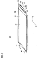
- flat battery 10 is configured as e.g. a lithium-ion secondary battery and has a structure that stacked electrode assembly 20 is accommodated together with an electrolytic solution between exterior members 30.
- Flat battery 10 includes electrodes 41 and 42 (referred to as "tabs") let to the outside from exterior members 30.
- electrodes 41 and 42 referred to as "tabs"
- FIG. 5 reference numeral 21 designates a positive electrode or a negative electrode. For purposes of clarity, only separators 22 are illustrated in FIG. 6 .
- Stacked electrode assembly 20 includes a positive electrode or electrodes, a negative electrode or electrodes and a separator or separators 22 stacked alternately together.
- the positive electrode has a positive electrode active material layer formed of e.g. a lithium-transition metal composite oxide such as LiMn 2 O 4
- the negative electrode has a negative electrode active material layer formed of e.g. a carbon material and a lithium-transition metal composite oxide.
- Separator 22 is formed of e.g. porous PE (polyethylene) having permeability to allow permeation of an electrolyte material.
- exterior members 30 are formed from sheets of e.g. polymer-metal laminate film in which a metal (or alloy) such as aluminum, stainless steel, nickel or cupper is coated with an insulating material such as propylene film.
- a metal or alloy
- Each of exterior members 30 includes body portion 31 covering stacked electrode assembly 20 and outer peripheral portion 32 extending along peripheral edge of body portion 31. Outer peripheral portions 32 are joined at part or the whole thereof by fusion bonding.
- Tabs 41 and 42 are adapted to take an electric current out of stacked electrode assembly 20 and arranged to extend on a front side of flat battery 10.
- Flat battery 10 has a plurality of joint parts 40 at which outer peripheral portions of separators 22 are joined with exterior members 30 in order to prevent a displacement of stacked electrode assembly 20.
- Flat battery 10 further includes holding part 50 formed at least between joint parts 40 to hold therein the electrolytic solution in such a manner that stacked electrode assembly 20 can be refilled with the electrolytic solution.
- the joining can be done by thermal fusion bonding, ultrasonic fusion bonding, welding etc.
- joint parts 40 are indicated by hatching for ease of understanding.
- the outer peripheral portions of separators 22 are joined with the exterior members 30 by forming a plurality of separate joint parts 40 as shown in FIGS. 5 , 6 and 7 rather than by forming a continuous single joint part.
- the continuous single joint part is hereinafter sometimes simply referred to as “continuous joint part" for the sake of simplicity.
- W1 (width) 2 mm
- W2 (distance) 1 mm
- W3 (length) 2 mm
- W4 distance from the fused joint (joint part 40) between the outer peripheral portions of separators 22 and exterior members 30 to the fused joint between outer peripheral portions 32 of exterior members 30
- 5 mm as shown in FIGS. 7(A) and (B) .
- the ratio of the sum of the areas of joint parts 40 to the total area of separator 22 can be set to 0.1% to 1%.
- the battery In the case of a battery in which separators are joined between exterior members by a continuous joint part, the battery has a so-called bag structure that an electrolytic solution is accumulated and sealed in a space between the continuous joint part and the joint between outer peripheral portions of the exterior members. In such a structure, it is not possible to make effective use of the sealed electrolytic solution.
- separators 22 are joined with the exterior member 30 by a plurality of joint parts 40 in the present embodiment.
- holding parts 50 are formed in a small space between separators 22 in this region so as to hold therein electrolytic solution 51 (see FIG. 6 ).
- Stacked electrode assembly 20 can be thus refilled with electrolytic solution 51 from holding part 50 under the action of capillarity when the amount of electrolytic solution 51 in stacked electrode assembly 20 becomes insufficient due to some reason.
- outer peripheral portion 32 of exterior member 30 includes a plurality of supporting parts 33 coupled by an adhesive to battery-supporting spacers 161 and extension part 34 located between supporting parts 33 and extending radially outwardly of the battery.
- the outer peripheral portion of separator 22 has tongue part 23 extending toward extension parts 34 of exterior members 30 such that joint parts 40 are formed on tongue part 23.
- Through holes 35 are formed in extension parts 34 such that pins in spacers 161 can be inserted in through holes 35 so as to restrict the supporting position of flat battery 10 relative to spacers 161.
- breakage line 61 that could be developed at or around joint parts 40 when a tensile force acts on separator 22 in the direction of outline arrow 60. Under such a tensile force, a tensile stress is exerted on each of joint parts 40 in the directions of solid-line arrows 62 as schematically indicated in FIG. 8(B) .
- breakage line 61 extends along the periphery (three sides) of each of joint parts 40, the battery is made able to withstand a larger tensile stress by increasing the sum of the perimeters of joint parts 40.
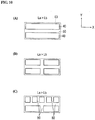
- the sum (La) of the perimeters of joint parts 40 is preferably made longer than the perimeter (Lb) of rectangle 63 of minimum area enclosing therein all of joint parts 40.
- the configuration of rectangle 63 can be defined as indicated by a broken line in FIGS. 9 and 10 .
- FIGS. 9(A) to (E) and FIGS. 10(A) to (C) examples of the shape and arrangement of a plurality of joint parts 40 and the relationship of La and Lb are schematically shown in FIGS. 9(A) to (E) and FIGS. 10(A) to (C) .
- joint parts 40 are all made the same in size and aligned in a line in the x-axis direction.
- the relationship of La and Lb is either La ⁇ Lb ( FIG. 9(C) ) or La > Lb ( FIG. 5 and FIG.9(A) ).
- the present invention is not limited to this example.
- joint parts 40 may be formed along the x-axis direction and arranged in two columns in the y-axis direction as shown in FIG. 10(A) .
- the condition of La > Lb is satisfied in this example.
- holding part 50 can be formed so as to hold therein electrolytic solution 51 and refill stacked electrode assembly 20 with electrolytic solution 51 as long as there are some spaces left at least between joint parts 40 in the vertical direction of the drawing.
- joint parts 40 may be arranged in two rows in the x-axis direction and in two columns in the y-axis direction.
- the condition of La > Lb is satisfied.
- joint parts 40 may be arranged in two columns in the y-axis direction with five joint parts 40 aligned in the x-axis direction in the upper column.
- the condition of La > Lb is satisfied in this example.
- the position of space between joint parts 40 in the upper column are displaced in the x-axis direction from the position of space between joint parts 40 in the lower column.
- holding part 50 can be formed so as to hold there in electrolytic solution 51 and refill stacked electrode assembly 20 with electrolytic solution 51.
- joint parts 40 is not limited to the direction parallel to the x-axis or y-axis direction. Although not shown in the drawings, it is feasible to arrange joint parts 40 in any direction inclined relative to the x-axis or y-axis direction.
- flat battery 10 has joint parts 40 at which the outer periphery of separator 22 is joined with exterior members 30 and holding part 50 formed at least between joint parts 40 so as to hold therein electrolytic solution 51 and refill stacked electrode assembly 20 with electrolytic solution 51. It is therefore possible to maintain the state in which stacked electrode assembly 20 contains a predetermined amount of electrolytic solution 51 over a long period of time by refilling stacked electrode assembly 20 with electrolytic solution 51 from holding part 50 between joint parts 40, whereby the secondary battery can secure battery performance during long-term use. Further, it is easier to release the gas accumulated between the stacked electrodes to outer peripheral portions 32 through the region between joint parts 40 and is possible to prevent a deterioration in power generating efficiency caused by the accumulated gas.
- separator 22 It is furthermore possible to improve the strength of separator 22 against tensile strength and prevent the occurrence of breakage in joint parts 40 in which separator 22 is made smaller in thickness by controlling the sum (La) of the perimeters of joint parts 40 to be longer than the perimeter of rectangle 63 of minimum area enclosing therein all of joint parts 40.
- each of outer peripheral portions 32 of exterior members 30 has a plurality of supporting parts 33 coupled to battery-supporting spacers 161 and extension part 34 located between supporting parts 33 and extending radially outwardly of the battery; and as the outer peripheral portion of separator 22 has tongue part 23 extending to between extension parts 34 of exterior members 30 such that joint parts 40 are formed on tongue part 23, it possible to make effective use of the dead space that is supported by spacers 161 and does not substantially contribute to power generation, increase the hold amount of electrolytic solution 51 and improve the operation lifetime of the battery.
- flat battery 10 includes a plurality of joint parts 40 at which outer peripheral portions of separators 22 are each joined with exterior members 30 and holding part 50 formed between joint parts 40 as shown in FIG. 11 .
- Joint parts 40 are arranged in joint regions 45, 46 and 47. In each of joint regions 45, 46 and 47, joint parts 40 are arranged adjacent to and at distance W2 away from each other.
- One joint region 44 is located at a distance that is longer than distance W2 away from the other joint region 46, 47.
- the sum of the perimeters of joint parts 40 is made longer than the perimeter of rectangle 65 of minimum area enclosing therein all of adjacent joint parts 40.
- the plurality of joint regions 45, 46 and 47 are provided on flat battery 10.
- Each of joint regions 45, 46 and 47 is defined as the region in which the plurality of joint parts 40 are arranged adjacent to each other. These joint regions 45, 46 and 47 are located at distance W5 from each other. Distance W5 is longer than distance W2 between adjacent joint parts 40.
- Holding portion 50 is formed between joint parts 40 and between joint regions 45, 46 and 47.
- joint parts 40 are formed so as to satisfy the condition of La (the sum of the perimeters of adjacent joint parts 40) > Lc (the perimeter of rectangle 65 of minimum area enclosing therein adjacent joint parts 40). This allows improvement in the tensile strength in joint region 45 as compared to the case forming a continuous joint in the region corresponding to joint region 45.
- joint parts 40 are formed so as to satisfy the condition of La > Lc in each of the other joint regions 46 and 47. This also allows improvement in the tensile strength in each of joint regions 46 and 47.
- the tensile strength of separator 22 can be improved throughout flat battery 10 by improving the tensile strength in each joint region 45, 46, 47.
- one joint region is constituted by four adjacent joint parts in the present another embodiment
- the number of joint parts in one joint region is not particularly limited and can be adjusted as appropriate.
- the number of joint regions in one flat battery is not also particularly limited and can be adjusted as appropriate although three joint regions are provided in one flat battery in the present another embodiment.
- positive and negative tabs 41 and 42 are provided on one side of exterior member 30 in flat battery 20 in the above embodiment, the present invention is applicable to the secondary battery in which positive and negative tabs are provided on different sides. It is alternatively feasible to provide holding part 50 and tabs on the same side.
- Example 1 Width W1 (mm) Length W3 (mm) Distance W2 (mm) Number of fused joints Fused joint area (mm 2 ) Perimeter (mm) Fused joint strength (N) Example 1 2 2 1 6 24 48 210 Example 2 1 1 1 12 12 48 212 Comparative Example 12 2 0 1 24 28 128
- flat battery 10 was provided to satisfy the condition: the sum of the perimeters of the fused joints (joint parts 40) (La) > the perimeter of rectangle 63 of minimum area enclosing all of fused joints 40.
- the fused joints of Example 1 and the fused joints of Example 2 are respectively schematically shown in FIGS. 12(A) and 12(B) .
- Examples 1 and 2 were different from each other in terms of the size of fused joints 40, the distance between fused joints 40 and the number of fused joints 40.
- the total area of fused joints 40 was made larger in Example 1 than in Example 2.
- holding part 50 was formed between the plurality of fused joints 40.
- Comparative Example a conventional flat battery with continuous fused joint 140 was provided (the number of fused joints was 1). In FIG. 12(C) , fused joint 140 of Comparative Example is shown. The total area of fused joint 140 was the same as that of Example 2.
- Flat batteries 10 of Examples 1 and 2 had a higher level of fused joint strength than that of the conventional flat battery of Comparative Example as is seen from TABLE 1. As is seen from comparison of Example 1 and Comparative Example, flat battery 10 of Example 1 had a higher fused joint strength than that of Comparative Example even though there was no difference in the total area of the fused joints. It has thus been shown by the above results that flat battery 10 according to the present invention can ensure improved strength against tensile force applied to fused joints 40 as compared to the conventional flat battery.
Landscapes
- Chemical & Material Sciences (AREA)
- Chemical Kinetics & Catalysis (AREA)
- Electrochemistry (AREA)
- General Chemical & Material Sciences (AREA)
- Engineering & Computer Science (AREA)
- Manufacturing & Machinery (AREA)
- Materials Engineering (AREA)
- Secondary Cells (AREA)
- Sealing Battery Cases Or Jackets (AREA)
- Cell Separators (AREA)
Claims (3)
- Sekundärbatterie (10), umfassend:- eine gestapelte Elektrodenanordnung (20) mit einer positiven Elektrode (41, 42), einer negativen Elektrode (41, 42) und einem Separator (22);- eine Elektrolytlösung (51), und- äußere Elemente (30), die die gestapelte Elektrodenanordnung (20) zusammen mit der Elektrolytlösung (51) dazwischen aufnehmen,- dadurch gekennzeichnet, dass die Sekundärbatterie (10) aufweist:- eine Mehrzahl von Verbindungsteilen (40), durch die ein Außenumfang des Separators (32) mit den äußeren Elementen (30) verbunden ist; und ein Halteteil (50), das zumindest zwischen den Verbindungsteilen (40) ausgebildet ist, um so darin die Elektrolytlösung (51) zu halten; und- wobei eine Summe von Umfängen der Verbindungsteile (40) größer als ein Umfang eines Rechtecks (63) eines minimalen Bereichs ist, der darin alle Verbindungsteile (40) umschließt.
- Sekundärbatterie gemäß Anspruch 1,
wobei die Sekundärbatterie (10) aufweist: einen ersten Verbindungsbereich (45, 46, 47), in dem die Mehrzahl von Verbindungsteilen (40) benachbart zu und an einem Abstand voneinander entfernt angeordnet ist; und einen zweiten Verbindungsbereich (45, 46, 47), der an einem Abstand angeordnet ist, der größer ist als der Abstand, der vom ersten Verbindungsbereich (45, 46, 47) entfernt ist, und in dem die Mehrzahl von Verbindungsteilen (40) benachbart zu und an einem Abstand voneinander entfernt angeordnet ist; und
wobei in jedem der ersten und zweiten Verbindungsbereiche (45, 46, 47) die Summe von Umfängen der benachbarten Verbindungsteile (40) größer als ein Umfang eines Rechtecks eines minimalen Bereichs ist, der darin alle benachbarten Verbindungsteile (40) umschließt. - Sekundärbatterie (10) gemäß Anspruch 1 oder 2,
wobei jeder der äußeren Umfangsbereiche (32) der äußeren Elemente (30) eine Mehrzahl von Abstützelementen (33), die mit einem Abstützelement (161) der Batterie (10) verbunden sind, und ein Verlängerungsteil (34) umfasst, das zwischen den Abstützteilen (33) angeordnet ist und sich nach außen von der Batterie (10) erstreckt; und
wobei der äußere Umfangsbereich des Separators (32) ein Zungenteil (23) umfasst, das sich zu den Verlängerungsteilen (34) der äußeren Elemente (30) erstreckt und auf dem die Verbindungsteile (40) ausgebildet sind.
Priority Applications (1)
| Application Number | Priority Date | Filing Date | Title |
|---|---|---|---|
| EP13194413.4A EP2704229B1 (de) | 2010-11-18 | 2011-10-05 | Sekundärbatterie |
Applications Claiming Priority (3)
| Application Number | Priority Date | Filing Date | Title |
|---|---|---|---|
| JP2010258365 | 2010-11-18 | ||
| JP2011185051A JP5397436B2 (ja) | 2010-11-18 | 2011-08-26 | 二次電池 |
| PCT/JP2011/072985 WO2012066863A1 (ja) | 2010-11-18 | 2011-10-05 | 二次電池 |
Related Child Applications (2)
| Application Number | Title | Priority Date | Filing Date |
|---|---|---|---|
| EP13194413.4A Division EP2704229B1 (de) | 2010-11-18 | 2011-10-05 | Sekundärbatterie |
| EP13194413.4A Division-Into EP2704229B1 (de) | 2010-11-18 | 2011-10-05 | Sekundärbatterie |
Publications (3)
| Publication Number | Publication Date |
|---|---|
| EP2642573A1 EP2642573A1 (de) | 2013-09-25 |
| EP2642573A4 EP2642573A4 (de) | 2014-04-09 |
| EP2642573B1 true EP2642573B1 (de) | 2017-06-28 |
Family
ID=46083805
Family Applications (2)
| Application Number | Title | Priority Date | Filing Date |
|---|---|---|---|
| EP13194413.4A Active EP2704229B1 (de) | 2010-11-18 | 2011-10-05 | Sekundärbatterie |
| EP11841468.9A Active EP2642573B1 (de) | 2010-11-18 | 2011-10-05 | Sekundärbatterie |
Family Applications Before (1)
| Application Number | Title | Priority Date | Filing Date |
|---|---|---|---|
| EP13194413.4A Active EP2704229B1 (de) | 2010-11-18 | 2011-10-05 | Sekundärbatterie |
Country Status (10)
| Country | Link |
|---|---|
| US (2) | US10763461B2 (de) |
| EP (2) | EP2704229B1 (de) |
| JP (1) | JP5397436B2 (de) |
| KR (2) | KR101451051B1 (de) |
| CN (2) | CN103594662B (de) |
| BR (2) | BR122014000560A2 (de) |
| MX (1) | MX2013002545A (de) |
| RU (2) | RU2529499C1 (de) |
| TW (2) | TWI478416B (de) |
| WO (1) | WO2012066863A1 (de) |
Families Citing this family (10)
| Publication number | Priority date | Publication date | Assignee | Title |
|---|---|---|---|---|
| JP5633932B2 (ja) * | 2011-02-23 | 2014-12-03 | Necエナジーデバイス株式会社 | 積層型の電池 |
| JP6102062B2 (ja) * | 2012-02-28 | 2017-03-29 | 株式会社Gsユアサ | 蓄電素子 |
| JP2013254629A (ja) * | 2012-06-06 | 2013-12-19 | Toyota Industries Corp | 蓄電装置及び二次電池 |
| CN104577004B (zh) * | 2014-12-25 | 2017-01-04 | 山东精工电子科技有限公司 | 一种固定隔膜的聚合物锂离子电池及其制作方法 |
| JP6659715B2 (ja) * | 2015-10-22 | 2020-03-04 | 株式会社エンビジョンAescジャパン | 組電池および組電池の製造方法 |
| WO2017098995A1 (ja) * | 2015-12-09 | 2017-06-15 | Necエナジーデバイス株式会社 | 電気化学デバイスとその製造方法 |
| US10367175B2 (en) | 2016-04-22 | 2019-07-30 | Bosch Bettery Systems LLC | Multicavity battery module |
| CN109309257A (zh) * | 2018-09-30 | 2019-02-05 | 联想(北京)有限公司 | 一种电池及电池生产方法 |
| JP2021039833A (ja) * | 2019-08-30 | 2021-03-11 | 積水化学工業株式会社 | 蓄電素子及び蓄電素子の製造方法 |
| KR102825293B1 (ko) * | 2020-01-15 | 2025-06-26 | 주식회사 엘지에너지솔루션 | 이차전지 |
Family Cites Families (27)
| Publication number | Priority date | Publication date | Assignee | Title |
|---|---|---|---|---|
| US4070528A (en) * | 1975-04-30 | 1978-01-24 | Esb Incorporated | Battery having porous inherently sealable separator |
| JPS6386268A (ja) * | 1986-09-29 | 1988-04-16 | Toshiba Battery Co Ltd | 扁平形電池 |
| JPH0636801A (ja) | 1992-07-13 | 1994-02-10 | Nippon Telegr & Teleph Corp <Ntt> | 角形非水電解液二次電池 |
| RU2105391C1 (ru) * | 1996-03-22 | 1998-02-20 | Куксенко Сергей Петрович | Литиевый источник тока |
| JP3511443B2 (ja) * | 1996-12-20 | 2004-03-29 | 株式会社リコー | 電池装置 |
| JPH11250873A (ja) | 1998-02-27 | 1999-09-17 | Japan Storage Battery Co Ltd | 非水電解質二次電池 |
| IL131842A (en) * | 1999-09-09 | 2007-03-08 | Unibat Ltd | Chargeable electrochemical cell |
| US6337154B1 (en) * | 1999-09-24 | 2002-01-08 | Electrofuel Inc. | Battery box with a metal plastic laminate end |
| JP3680744B2 (ja) * | 2001-02-23 | 2005-08-10 | 三菱マテリアル株式会社 | リチウムイオンポリマー二次電池 |
| JP3588338B2 (ja) * | 2001-05-31 | 2004-11-10 | 三洋電機株式会社 | 非水電解質二次電池 |
| JP3934888B2 (ja) * | 2001-06-28 | 2007-06-20 | Necトーキン株式会社 | 積層型二次電池 |
| JP2003142043A (ja) * | 2001-07-09 | 2003-05-16 | Hitachi Maxell Ltd | 電 池 |
| TW508857B (en) * | 2001-07-18 | 2002-11-01 | Enemax Internatiional Pte Ltd | Closed-type lead accumulator |
| JP2003092092A (ja) * | 2001-09-18 | 2003-03-28 | Matsushita Electric Ind Co Ltd | 二次電池とその製法 |
| TWM253909U (en) * | 2003-12-29 | 2004-12-21 | Fu-Chung Wu | Improved structure of battery |
| KR100645263B1 (ko) * | 2004-02-18 | 2006-11-14 | 주식회사 엘지화학 | 보호회로부가 구비된 일체형 캠 어셈블리 및 그것이구비되어 있는 이차전지 |
| JP4670275B2 (ja) * | 2004-08-12 | 2011-04-13 | 日産自動車株式会社 | バイポーラ電池および組電池 |
| CN100444430C (zh) * | 2005-06-16 | 2008-12-17 | 日产自动车株式会社 | 扁平型电池及采用该扁平型电池的电池组 |
| JP4920957B2 (ja) * | 2005-11-21 | 2012-04-18 | Necエナジーデバイス株式会社 | 積層型リチウムイオンポリマー電池 |
| JP4803360B2 (ja) * | 2005-12-02 | 2011-10-26 | 三菱自動車工業株式会社 | リチウムイオン二次電池 |
| JP2007250319A (ja) * | 2006-03-15 | 2007-09-27 | Nec Tokin Corp | 積層型電池 |
| JP2007287724A (ja) * | 2006-04-12 | 2007-11-01 | Nec Tokin Corp | 積層型電気化学デバイス |
| KR100894409B1 (ko) * | 2006-05-15 | 2009-04-24 | 주식회사 엘지화학 | 전지케이스에 분리막을 고정시켜 안전성을 향상시킨이차전지 |
| JP4925427B2 (ja) * | 2006-09-27 | 2012-04-25 | 日立マクセルエナジー株式会社 | ラミネート形非水二次電池 |
| JP5392809B2 (ja) * | 2008-07-18 | 2014-01-22 | Necエナジーデバイス株式会社 | リチウム二次電池 |
| JP5334162B2 (ja) * | 2008-09-08 | 2013-11-06 | Necエナジーデバイス株式会社 | 積層型二次電池 |
| JP2010153140A (ja) * | 2008-12-24 | 2010-07-08 | Nissan Motor Co Ltd | 非水電解質二次電池 |
-
2011
- 2011-08-26 JP JP2011185051A patent/JP5397436B2/ja active Active
- 2011-10-05 BR BR122014000560A patent/BR122014000560A2/pt not_active IP Right Cessation
- 2011-10-05 MX MX2013002545A patent/MX2013002545A/es active IP Right Grant
- 2011-10-05 CN CN201310589067.9A patent/CN103594662B/zh active Active
- 2011-10-05 KR KR1020137008645A patent/KR101451051B1/ko active Active
- 2011-10-05 EP EP13194413.4A patent/EP2704229B1/de active Active
- 2011-10-05 RU RU2013127512/07A patent/RU2529499C1/ru not_active IP Right Cessation
- 2011-10-05 US US13/885,572 patent/US10763461B2/en active Active
- 2011-10-05 BR BR112013005893A patent/BR112013005893A2/pt not_active IP Right Cessation
- 2011-10-05 EP EP11841468.9A patent/EP2642573B1/de active Active
- 2011-10-05 CN CN201180049188.3A patent/CN103155259B/zh active Active
- 2011-10-05 KR KR1020137032174A patent/KR101484437B1/ko active Active
- 2011-10-05 WO PCT/JP2011/072985 patent/WO2012066863A1/ja not_active Ceased
- 2011-11-17 TW TW102142688A patent/TWI478416B/zh not_active IP Right Cessation
- 2011-11-17 TW TW100142044A patent/TWI450430B/zh not_active IP Right Cessation
-
2013
- 2013-11-28 RU RU2013153085/07A patent/RU2560134C2/ru not_active IP Right Cessation
-
2014
- 2014-02-19 US US14/184,289 patent/US10763462B2/en active Active
Non-Patent Citations (1)
| Title |
|---|
| None * |
Also Published As
| Publication number | Publication date |
|---|---|
| TW201222916A (en) | 2012-06-01 |
| TWI478416B (zh) | 2015-03-21 |
| CN103594662B (zh) | 2016-01-13 |
| WO2012066863A1 (ja) | 2012-05-24 |
| BR122014000560A2 (pt) | 2016-05-17 |
| US10763461B2 (en) | 2020-09-01 |
| KR101451051B1 (ko) | 2014-10-15 |
| EP2642573A4 (de) | 2014-04-09 |
| RU2529499C1 (ru) | 2014-09-27 |
| BR112013005893A2 (pt) | 2016-05-10 |
| KR20130051002A (ko) | 2013-05-16 |
| MX2013002545A (es) | 2013-03-18 |
| KR20140013063A (ko) | 2014-02-04 |
| RU2013153085A (ru) | 2015-06-10 |
| TW201419627A (zh) | 2014-05-16 |
| TWI450430B (zh) | 2014-08-21 |
| EP2704229A1 (de) | 2014-03-05 |
| RU2560134C2 (ru) | 2015-08-20 |
| KR101484437B1 (ko) | 2015-01-19 |
| JP5397436B2 (ja) | 2014-01-22 |
| US10763462B2 (en) | 2020-09-01 |
| EP2642573A1 (de) | 2013-09-25 |
| EP2704229B1 (de) | 2018-03-07 |
| US20130236792A1 (en) | 2013-09-12 |
| CN103155259B (zh) | 2015-04-08 |
| JP2012124150A (ja) | 2012-06-28 |
| CN103155259A (zh) | 2013-06-12 |
| CN103594662A (zh) | 2014-02-19 |
| US20140170469A1 (en) | 2014-06-19 |
Similar Documents
| Publication | Publication Date | Title |
|---|---|---|
| EP2704229B1 (de) | Sekundärbatterie | |
| US9496542B2 (en) | Battery module of improved reliability and battery pack employed with the same | |
| KR102270266B1 (ko) | 버스바 어셈블리를 구비한 배터리 모듈 | |
| KR101509474B1 (ko) | 단일 전극단자 결합부를 가진 전지 조합체 | |
| KR101125592B1 (ko) | 수명 특성과 안전성이 우수한 고용량 전지셀 | |
| KR20180107569A (ko) | 배터리 팩 | |
| WO2019003928A1 (ja) | バスバー及び電池積層体 | |
| KR20140049654A (ko) | 내압성과 안정성이 향상된 전극리드를 포함하는 전지셀 | |
| JPWO2019124109A1 (ja) | バスバー及び電池積層体 | |
| US10892453B2 (en) | Battery pack and method of manufacturing battery pack | |
| KR102894082B1 (ko) | 전지셀 및 이를 포함하는 전지 모듈 | |
| KR102167431B1 (ko) | 두께가 상이한 단일 전극리드로 결합된 전지셀 어셈블리 | |
| JP2014212033A (ja) | 電池モジュール | |
| JP5382079B2 (ja) | 二次電池 | |
| JP6926509B2 (ja) | 蓄電装置 | |
| EP4517896B1 (de) | Wiederaufladbare batterie | |
| WO2021106516A1 (ja) | 蓄電モジュール | |
| KR20230008566A (ko) | 이차전지 및 그 제조방법 | |
| JP2010016307A (ja) | モジュール型蓄電装置 |
Legal Events
| Date | Code | Title | Description |
|---|---|---|---|
| PUAI | Public reference made under article 153(3) epc to a published international application that has entered the european phase |
Free format text: ORIGINAL CODE: 0009012 |
|
| 17P | Request for examination filed |
Effective date: 20130311 |
|
| AK | Designated contracting states |
Kind code of ref document: A1 Designated state(s): AL AT BE BG CH CY CZ DE DK EE ES FI FR GB GR HR HU IE IS IT LI LT LU LV MC MK MT NL NO PL PT RO RS SE SI SK SM TR |
|
| DAX | Request for extension of the european patent (deleted) | ||
| REG | Reference to a national code |
Ref country code: DE Ref legal event code: R079 Ref document number: 602011039202 Country of ref document: DE Free format text: PREVIOUS MAIN CLASS: H01M0010040000 Ipc: H01M0002020000 |
|
| A4 | Supplementary search report drawn up and despatched |
Effective date: 20140312 |
|
| RIC1 | Information provided on ipc code assigned before grant |
Ipc: H01M 2/10 20060101ALI20140306BHEP Ipc: H01M 2/02 20060101AFI20140306BHEP Ipc: H01M 2/36 20060101ALI20140306BHEP |
|
| GRAP | Despatch of communication of intention to grant a patent |
Free format text: ORIGINAL CODE: EPIDOSNIGR1 |
|
| INTG | Intention to grant announced |
Effective date: 20170317 |
|
| GRAS | Grant fee paid |
Free format text: ORIGINAL CODE: EPIDOSNIGR3 |
|
| GRAA | (expected) grant |
Free format text: ORIGINAL CODE: 0009210 |
|
| AK | Designated contracting states |
Kind code of ref document: B1 Designated state(s): AL AT BE BG CH CY CZ DE DK EE ES FI FR GB GR HR HU IE IS IT LI LT LU LV MC MK MT NL NO PL PT RO RS SE SI SK SM TR |
|
| REG | Reference to a national code |
Ref country code: GB Ref legal event code: FG4D |
|
| REG | Reference to a national code |
Ref country code: CH Ref legal event code: EP |
|
| REG | Reference to a national code |
Ref country code: AT Ref legal event code: REF Ref document number: 905558 Country of ref document: AT Kind code of ref document: T Effective date: 20170715 |
|
| REG | Reference to a national code |
Ref country code: IE Ref legal event code: FG4D |
|
| REG | Reference to a national code |
Ref country code: DE Ref legal event code: R096 Ref document number: 602011039202 Country of ref document: DE |
|
| REG | Reference to a national code |
Ref country code: FR Ref legal event code: PLFP Year of fee payment: 7 |
|
| PG25 | Lapsed in a contracting state [announced via postgrant information from national office to epo] |
Ref country code: NO Free format text: LAPSE BECAUSE OF FAILURE TO SUBMIT A TRANSLATION OF THE DESCRIPTION OR TO PAY THE FEE WITHIN THE PRESCRIBED TIME-LIMIT Effective date: 20170928 Ref country code: HR Free format text: LAPSE BECAUSE OF FAILURE TO SUBMIT A TRANSLATION OF THE DESCRIPTION OR TO PAY THE FEE WITHIN THE PRESCRIBED TIME-LIMIT Effective date: 20170628 Ref country code: GR Free format text: LAPSE BECAUSE OF FAILURE TO SUBMIT A TRANSLATION OF THE DESCRIPTION OR TO PAY THE FEE WITHIN THE PRESCRIBED TIME-LIMIT Effective date: 20170929 Ref country code: LT Free format text: LAPSE BECAUSE OF FAILURE TO SUBMIT A TRANSLATION OF THE DESCRIPTION OR TO PAY THE FEE WITHIN THE PRESCRIBED TIME-LIMIT Effective date: 20170628 Ref country code: FI Free format text: LAPSE BECAUSE OF FAILURE TO SUBMIT A TRANSLATION OF THE DESCRIPTION OR TO PAY THE FEE WITHIN THE PRESCRIBED TIME-LIMIT Effective date: 20170628 |
|
| REG | Reference to a national code |
Ref country code: NL Ref legal event code: MP Effective date: 20170628 |
|
| REG | Reference to a national code |
Ref country code: LT Ref legal event code: MG4D |
|
| REG | Reference to a national code |
Ref country code: AT Ref legal event code: MK05 Ref document number: 905558 Country of ref document: AT Kind code of ref document: T Effective date: 20170628 |
|
| PG25 | Lapsed in a contracting state [announced via postgrant information from national office to epo] |
Ref country code: NL Free format text: LAPSE BECAUSE OF FAILURE TO SUBMIT A TRANSLATION OF THE DESCRIPTION OR TO PAY THE FEE WITHIN THE PRESCRIBED TIME-LIMIT Effective date: 20170628 Ref country code: LV Free format text: LAPSE BECAUSE OF FAILURE TO SUBMIT A TRANSLATION OF THE DESCRIPTION OR TO PAY THE FEE WITHIN THE PRESCRIBED TIME-LIMIT Effective date: 20170628 Ref country code: RS Free format text: LAPSE BECAUSE OF FAILURE TO SUBMIT A TRANSLATION OF THE DESCRIPTION OR TO PAY THE FEE WITHIN THE PRESCRIBED TIME-LIMIT Effective date: 20170628 Ref country code: BG Free format text: LAPSE BECAUSE OF FAILURE TO SUBMIT A TRANSLATION OF THE DESCRIPTION OR TO PAY THE FEE WITHIN THE PRESCRIBED TIME-LIMIT Effective date: 20170928 Ref country code: SE Free format text: LAPSE BECAUSE OF FAILURE TO SUBMIT A TRANSLATION OF THE DESCRIPTION OR TO PAY THE FEE WITHIN THE PRESCRIBED TIME-LIMIT Effective date: 20170628 |
|
| PG25 | Lapsed in a contracting state [announced via postgrant information from national office to epo] |
Ref country code: EE Free format text: LAPSE BECAUSE OF FAILURE TO SUBMIT A TRANSLATION OF THE DESCRIPTION OR TO PAY THE FEE WITHIN THE PRESCRIBED TIME-LIMIT Effective date: 20170628 Ref country code: RO Free format text: LAPSE BECAUSE OF FAILURE TO SUBMIT A TRANSLATION OF THE DESCRIPTION OR TO PAY THE FEE WITHIN THE PRESCRIBED TIME-LIMIT Effective date: 20170628 Ref country code: CZ Free format text: LAPSE BECAUSE OF FAILURE TO SUBMIT A TRANSLATION OF THE DESCRIPTION OR TO PAY THE FEE WITHIN THE PRESCRIBED TIME-LIMIT Effective date: 20170628 Ref country code: SK Free format text: LAPSE BECAUSE OF FAILURE TO SUBMIT A TRANSLATION OF THE DESCRIPTION OR TO PAY THE FEE WITHIN THE PRESCRIBED TIME-LIMIT Effective date: 20170628 Ref country code: AT Free format text: LAPSE BECAUSE OF FAILURE TO SUBMIT A TRANSLATION OF THE DESCRIPTION OR TO PAY THE FEE WITHIN THE PRESCRIBED TIME-LIMIT Effective date: 20170628 |
|
| PG25 | Lapsed in a contracting state [announced via postgrant information from national office to epo] |
Ref country code: PL Free format text: LAPSE BECAUSE OF FAILURE TO SUBMIT A TRANSLATION OF THE DESCRIPTION OR TO PAY THE FEE WITHIN THE PRESCRIBED TIME-LIMIT Effective date: 20170628 Ref country code: IT Free format text: LAPSE BECAUSE OF FAILURE TO SUBMIT A TRANSLATION OF THE DESCRIPTION OR TO PAY THE FEE WITHIN THE PRESCRIBED TIME-LIMIT Effective date: 20170628 Ref country code: ES Free format text: LAPSE BECAUSE OF FAILURE TO SUBMIT A TRANSLATION OF THE DESCRIPTION OR TO PAY THE FEE WITHIN THE PRESCRIBED TIME-LIMIT Effective date: 20170628 Ref country code: IS Free format text: LAPSE BECAUSE OF FAILURE TO SUBMIT A TRANSLATION OF THE DESCRIPTION OR TO PAY THE FEE WITHIN THE PRESCRIBED TIME-LIMIT Effective date: 20171028 Ref country code: SM Free format text: LAPSE BECAUSE OF FAILURE TO SUBMIT A TRANSLATION OF THE DESCRIPTION OR TO PAY THE FEE WITHIN THE PRESCRIBED TIME-LIMIT Effective date: 20170628 |
|
| REG | Reference to a national code |
Ref country code: DE Ref legal event code: R097 Ref document number: 602011039202 Country of ref document: DE |
|
| PG25 | Lapsed in a contracting state [announced via postgrant information from national office to epo] |
Ref country code: DK Free format text: LAPSE BECAUSE OF FAILURE TO SUBMIT A TRANSLATION OF THE DESCRIPTION OR TO PAY THE FEE WITHIN THE PRESCRIBED TIME-LIMIT Effective date: 20170628 |
|
| PLBE | No opposition filed within time limit |
Free format text: ORIGINAL CODE: 0009261 |
|
| STAA | Information on the status of an ep patent application or granted ep patent |
Free format text: STATUS: NO OPPOSITION FILED WITHIN TIME LIMIT |
|
| PG25 | Lapsed in a contracting state [announced via postgrant information from national office to epo] |
Ref country code: MC Free format text: LAPSE BECAUSE OF FAILURE TO SUBMIT A TRANSLATION OF THE DESCRIPTION OR TO PAY THE FEE WITHIN THE PRESCRIBED TIME-LIMIT Effective date: 20170628 |
|
| REG | Reference to a national code |
Ref country code: CH Ref legal event code: PL |
|
| 26N | No opposition filed |
Effective date: 20180329 |
|
| REG | Reference to a national code |
Ref country code: IE Ref legal event code: MM4A |
|
| PG25 | Lapsed in a contracting state [announced via postgrant information from national office to epo] |
Ref country code: LI Free format text: LAPSE BECAUSE OF NON-PAYMENT OF DUE FEES Effective date: 20171031 Ref country code: CH Free format text: LAPSE BECAUSE OF NON-PAYMENT OF DUE FEES Effective date: 20171031 Ref country code: LU Free format text: LAPSE BECAUSE OF NON-PAYMENT OF DUE FEES Effective date: 20171005 |
|
| REG | Reference to a national code |
Ref country code: BE Ref legal event code: MM Effective date: 20171031 |
|
| PG25 | Lapsed in a contracting state [announced via postgrant information from national office to epo] |
Ref country code: SI Free format text: LAPSE BECAUSE OF FAILURE TO SUBMIT A TRANSLATION OF THE DESCRIPTION OR TO PAY THE FEE WITHIN THE PRESCRIBED TIME-LIMIT Effective date: 20170628 Ref country code: BE Free format text: LAPSE BECAUSE OF NON-PAYMENT OF DUE FEES Effective date: 20171031 |
|
| REG | Reference to a national code |
Ref country code: FR Ref legal event code: PLFP Year of fee payment: 8 |
|
| PG25 | Lapsed in a contracting state [announced via postgrant information from national office to epo] |
Ref country code: MT Free format text: LAPSE BECAUSE OF NON-PAYMENT OF DUE FEES Effective date: 20171005 |
|
| PG25 | Lapsed in a contracting state [announced via postgrant information from national office to epo] |
Ref country code: IE Free format text: LAPSE BECAUSE OF NON-PAYMENT OF DUE FEES Effective date: 20171005 |
|
| PG25 | Lapsed in a contracting state [announced via postgrant information from national office to epo] |
Ref country code: HU Free format text: LAPSE BECAUSE OF FAILURE TO SUBMIT A TRANSLATION OF THE DESCRIPTION OR TO PAY THE FEE WITHIN THE PRESCRIBED TIME-LIMIT; INVALID AB INITIO Effective date: 20111005 |
|
| REG | Reference to a national code |
Ref country code: DE Ref legal event code: R082 Ref document number: 602011039202 Country of ref document: DE Representative=s name: HOEFER & PARTNER PATENTANWAELTE MBB, DE Ref country code: DE Ref legal event code: R081 Ref document number: 602011039202 Country of ref document: DE Owner name: ENVISION AESC JAPAN LTD., ZAMA-SHI, JP Free format text: FORMER OWNER: NISSAN MOTOR CO., LTD., YOKOHAMA-SHI, KANAGAWA-KEN, JP |
|
| PG25 | Lapsed in a contracting state [announced via postgrant information from national office to epo] |
Ref country code: CY Free format text: LAPSE BECAUSE OF NON-PAYMENT OF DUE FEES Effective date: 20170628 |
|
| PG25 | Lapsed in a contracting state [announced via postgrant information from national office to epo] |
Ref country code: MK Free format text: LAPSE BECAUSE OF FAILURE TO SUBMIT A TRANSLATION OF THE DESCRIPTION OR TO PAY THE FEE WITHIN THE PRESCRIBED TIME-LIMIT Effective date: 20170628 |
|
| PG25 | Lapsed in a contracting state [announced via postgrant information from national office to epo] |
Ref country code: TR Free format text: LAPSE BECAUSE OF FAILURE TO SUBMIT A TRANSLATION OF THE DESCRIPTION OR TO PAY THE FEE WITHIN THE PRESCRIBED TIME-LIMIT Effective date: 20170628 |
|
| PG25 | Lapsed in a contracting state [announced via postgrant information from national office to epo] |
Ref country code: PT Free format text: LAPSE BECAUSE OF FAILURE TO SUBMIT A TRANSLATION OF THE DESCRIPTION OR TO PAY THE FEE WITHIN THE PRESCRIBED TIME-LIMIT Effective date: 20170628 |
|
| PG25 | Lapsed in a contracting state [announced via postgrant information from national office to epo] |
Ref country code: AL Free format text: LAPSE BECAUSE OF FAILURE TO SUBMIT A TRANSLATION OF THE DESCRIPTION OR TO PAY THE FEE WITHIN THE PRESCRIBED TIME-LIMIT Effective date: 20170628 |
|
| REG | Reference to a national code |
Ref country code: DE Ref legal event code: R079 Ref document number: 602011039202 Country of ref document: DE Free format text: PREVIOUS MAIN CLASS: H01M0002020000 Ipc: H01M0050100000 |
|
| P01 | Opt-out of the competence of the unified patent court (upc) registered |
Effective date: 20230330 |
|
| PGFP | Annual fee paid to national office [announced via postgrant information from national office to epo] |
Ref country code: GB Payment date: 20250821 Year of fee payment: 15 |
|
| PGFP | Annual fee paid to national office [announced via postgrant information from national office to epo] |
Ref country code: FR Payment date: 20250821 Year of fee payment: 15 |
|
| PGFP | Annual fee paid to national office [announced via postgrant information from national office to epo] |
Ref country code: DE Payment date: 20250827 Year of fee payment: 15 |