EP2642576B1 - Pile au lithium-ion et chargeur associé - Google Patents
Pile au lithium-ion et chargeur associé Download PDFInfo
- Publication number
- EP2642576B1 EP2642576B1 EP10859653.7A EP10859653A EP2642576B1 EP 2642576 B1 EP2642576 B1 EP 2642576B1 EP 10859653 A EP10859653 A EP 10859653A EP 2642576 B1 EP2642576 B1 EP 2642576B1
- Authority
- EP
- European Patent Office
- Prior art keywords
- hole
- plate
- positive
- positioning
- negative
- Prior art date
- Legal status (The legal status is an assumption and is not a legal conclusion. Google has not performed a legal analysis and makes no representation as to the accuracy of the status listed.)
- Not-in-force
Links
Images





Classifications
-
- H—ELECTRICITY
- H01—ELECTRIC ELEMENTS
- H01M—PROCESSES OR MEANS, e.g. BATTERIES, FOR THE DIRECT CONVERSION OF CHEMICAL ENERGY INTO ELECTRICAL ENERGY
- H01M10/00—Secondary cells; Manufacture thereof
- H01M10/42—Methods or arrangements for servicing or maintenance of secondary cells or secondary half-cells
- H01M10/46—Accumulators structurally combined with charging apparatus
-
- H—ELECTRICITY
- H01—ELECTRIC ELEMENTS
- H01M—PROCESSES OR MEANS, e.g. BATTERIES, FOR THE DIRECT CONVERSION OF CHEMICAL ENERGY INTO ELECTRICAL ENERGY
- H01M10/00—Secondary cells; Manufacture thereof
- H01M10/05—Accumulators with non-aqueous electrolyte
- H01M10/052—Li-accumulators
-
- H—ELECTRICITY
- H01—ELECTRIC ELEMENTS
- H01M—PROCESSES OR MEANS, e.g. BATTERIES, FOR THE DIRECT CONVERSION OF CHEMICAL ENERGY INTO ELECTRICAL ENERGY
- H01M10/00—Secondary cells; Manufacture thereof
- H01M10/05—Accumulators with non-aqueous electrolyte
- H01M10/052—Li-accumulators
- H01M10/0525—Rocking-chair batteries, i.e. batteries with lithium insertion or intercalation in both electrodes; Lithium-ion batteries
-
- H—ELECTRICITY
- H01—ELECTRIC ELEMENTS
- H01M—PROCESSES OR MEANS, e.g. BATTERIES, FOR THE DIRECT CONVERSION OF CHEMICAL ENERGY INTO ELECTRICAL ENERGY
- H01M50/00—Constructional details or processes of manufacture of the non-active parts of electrochemical cells other than fuel cells, e.g. hybrid cells
- H01M50/10—Primary casings; Jackets or wrappings
- H01M50/102—Primary casings; Jackets or wrappings characterised by their shape or physical structure
- H01M50/107—Primary casings; Jackets or wrappings characterised by their shape or physical structure having curved cross-section, e.g. round or elliptic
-
- H—ELECTRICITY
- H01—ELECTRIC ELEMENTS
- H01M—PROCESSES OR MEANS, e.g. BATTERIES, FOR THE DIRECT CONVERSION OF CHEMICAL ENERGY INTO ELECTRICAL ENERGY
- H01M50/00—Constructional details or processes of manufacture of the non-active parts of electrochemical cells other than fuel cells, e.g. hybrid cells
- H01M50/20—Mountings; Secondary casings or frames; Racks, modules or packs; Suspension devices; Shock absorbers; Transport or carrying devices; Holders
- H01M50/204—Racks, modules or packs for multiple batteries or multiple cells
- H01M50/207—Racks, modules or packs for multiple batteries or multiple cells characterised by their shape
- H01M50/213—Racks, modules or packs for multiple batteries or multiple cells characterised by their shape adapted for cells having curved cross-section, e.g. round or elliptic
-
- H—ELECTRICITY
- H01—ELECTRIC ELEMENTS
- H01M—PROCESSES OR MEANS, e.g. BATTERIES, FOR THE DIRECT CONVERSION OF CHEMICAL ENERGY INTO ELECTRICAL ENERGY
- H01M50/00—Constructional details or processes of manufacture of the non-active parts of electrochemical cells other than fuel cells, e.g. hybrid cells
- H01M50/50—Current conducting connections for cells or batteries
-
- H—ELECTRICITY
- H01—ELECTRIC ELEMENTS
- H01M—PROCESSES OR MEANS, e.g. BATTERIES, FOR THE DIRECT CONVERSION OF CHEMICAL ENERGY INTO ELECTRICAL ENERGY
- H01M50/00—Constructional details or processes of manufacture of the non-active parts of electrochemical cells other than fuel cells, e.g. hybrid cells
- H01M50/50—Current conducting connections for cells or batteries
- H01M50/543—Terminals
- H01M50/552—Terminals characterised by their shape
- H01M50/559—Terminals adapted for cells having curved cross-section, e.g. round, elliptic or button cells
-
- H—ELECTRICITY
- H02—GENERATION; CONVERSION OR DISTRIBUTION OF ELECTRIC POWER
- H02J—ELECTRIC POWER NETWORKS; CIRCUIT ARRANGEMENTS OR SYSTEMS FOR SUPPLYING OR DISTRIBUTING ELECTRIC POWER; SYSTEMS FOR STORING ELECTRIC ENERGY
- H02J7/00—Circuit arrangements for charging or discharging batteries or for supplying loads from batteries
- H02J7/70—Circuit arrangements for charging or discharging batteries or for supplying loads from batteries characterised by the mechanical construction
-
- H—ELECTRICITY
- H02—GENERATION; CONVERSION OR DISTRIBUTION OF ELECTRIC POWER
- H02J—ELECTRIC POWER NETWORKS; CIRCUIT ARRANGEMENTS OR SYSTEMS FOR SUPPLYING OR DISTRIBUTING ELECTRIC POWER; SYSTEMS FOR STORING ELECTRIC ENERGY
- H02J7/00—Circuit arrangements for charging or discharging batteries or for supplying loads from batteries
- H02J7/70—Circuit arrangements for charging or discharging batteries or for supplying loads from batteries characterised by the mechanical construction
- H02J7/751—Circuit arrangements for charging or discharging batteries or for supplying loads from batteries characterised by the mechanical construction concerning the insertion or the connection of the batteries
-
- Y—GENERAL TAGGING OF NEW TECHNOLOGICAL DEVELOPMENTS; GENERAL TAGGING OF CROSS-SECTIONAL TECHNOLOGIES SPANNING OVER SEVERAL SECTIONS OF THE IPC; TECHNICAL SUBJECTS COVERED BY FORMER USPC CROSS-REFERENCE ART COLLECTIONS [XRACs] AND DIGESTS
- Y02—TECHNOLOGIES OR APPLICATIONS FOR MITIGATION OR ADAPTATION AGAINST CLIMATE CHANGE
- Y02E—REDUCTION OF GREENHOUSE GAS [GHG] EMISSIONS, RELATED TO ENERGY GENERATION, TRANSMISSION OR DISTRIBUTION
- Y02E60/00—Enabling technologies; Technologies with a potential or indirect contribution to GHG emissions mitigation
- Y02E60/10—Energy storage using batteries
Definitions
- the present invention relates to a lithium ion battery and a charger of the lithium ion battery, especially to a portable lithium ion battery with features of easy-assembly, simple structure and high efficiency and a charger thereof. Moreover, the lithium ion battery is detached from the charger conveniently.
- the lithium ion battery available now consists of a shell, a locating seat, an end cover, a battery cell, a positive contact, a positive plate, a negative plate, a positive connecting plate and a negative connecting plate.
- the negative plate is disposed on the locating seat while the positive plate is arranged at the end cover.
- the shell is formed by two half housings. The two half housings are connected by ultrasonic welding. The locating seat and the end cover are disposed on the shell.
- the lithium ion battery has shortcomings of complicated assembly and low efficiency.
- the document US 2009/011286 A1 discloses the features mentionned in the pre-characterizing parts of the appended claim 1 and claim 6.
- a lithium ion battery that includes a shell, a locating seat, an end cover, a battery cell, a positive contact, a positive plate, a negative plate, a positive connecting plate and a negative connecting plate.
- the lithium ion battery features on that the shell is a cylinder having an upper opening and a contact extending hole on a center of a bottom plate of the shell.
- a mounting hole of the negative plate is arranged at an upper end face of the locating seat.
- the locating seat also includes a through hole for positive plate and a through hole for negative plate while the through hole for negative plate communicates with the mounting hole.
- An opening of a lower end face of the through hole for positive plate and an opening of a lower end face of the through hole for negative plate are respectively arranged with a positive guide block and a negative guide block.
- the positive guide block and the negative guide block are supported by and cooperated with an end part of the battery cell.
- a central hole is set on the cap cover and a positive plate slot around the central hole is located at an upper end face of the cap cover.
- a guide hole of the positive plate is penetrating the end cover and a lower end face of the end cover is tightly pressed on the negative plate and the locating seat.
- the end cover is detachably connected with the upper opening of the shell.
- a cover edge of the end cover cooperates with an end face of the upper opening of the shell.
- the positive plate is circular and is disposed in the positive plate slot of the end cover.
- a positive conductive plate of the positive plate is passed through the guide hole of the end cover, and the through hole for positive plate to cooperate with the positive connecting plate.
- the negative plate is mounted in the mounting hole of the locating seat and a negative conductive plate of the negative plate is passed through the through hole for negative plate to cooperate with the negative connecting plate.
- the positive contact extends out from a contact extending hole.
- the lower end face of the end cover is disposed with a circular groove while a positioning base is arranged radially outside the circular groove.
- the circular groove and the positive plate slot are communicated with each other by the guide hole of the positive plate.
- the upper end face of the locating seat is further disposed with a circular base around the mounting hole.
- Both the through hole for positive plate and the through hole for negative plate are mounted on the circular base.
- the through hole for negative plate communicates with the mounting hole.
- a lower end of an inner circular wall of the circular groove is leaning against the negative plate while a lower end of an outer circular wall of the circular groove cooperates with an end part of the locating seat disposed radially outside the circular base.
- the lower end face of the end cover is arranged with two hooks spaced evenly in a circle thereof.
- a periphery of the locating seat is disposed evenly with two positioning slots while a wall of the shell is arranged with locking holes.
- a rod part of the hook cooperates with the positioning slot and a hook part of the hook is locked with the locking hole.
- An outer surface of one end of the shell having the opening is disposed evenly with at least two projections in a circle thereof.
- An axial locking slot is located on the projection and the shell.
- a periphery of the cover edge of the end cover is disposed evenly with at least two connecting blocks. Locking blocks on a lower part of the cover edge of the end cover are integrated with the connecting block respectively.
- the projection and the connecting block are fastened with each other to form a positioning block.
- the locking block is mounted into the locking slot.
- the lower end face of the end cover is arranged with two hooks spaced evenly in a circle thereof.
- a periphery of the locating seat is disposed evenly with two positioning slots while a wall of the cylinder is arranged with locking holes.
- a rod part of the hook cooperates with the positioning slot and a hook part of the hook is locked with the locking hole.
- a charger of the lithium ion battery according to the present invention is composed of a charging circuit board, a charging socket and a housing.
- the charger features on that it further includes a positive spring and a negative spring.
- the housing includes a seat and a cap cover.
- An interface is disposed on an upper end of the seat and a curved locking slot is on the interface.
- a circular support base is set on an upper part of the interface while a limit base is at a part that connects the circular support base and the interface with each other.
- a receiving space is mounted on a lower end face of the seat.
- An insertion hole is on top of the cap cover.
- a stopper base and a curved locking protuberance are disposed in a space of the cap cover.
- the charging circuit board is disposed on the circular support base while the positive spring and the negative spring are arranged in the receiving space 915 and passed through the receiving space to connect to the charging circuit board.
- the negative spring is located in a space of the positive spring.
- the positive spring and the negative spring respectively cooperate with the positive plate and the negative plate.
- the charging socket is arranged at the charging circuit board and is corresponding to the insertion hole of the cap cover.
- the curved locking protuberance of the cap cover cooperates with the curved locking slot of the seat.
- the limit base and the stopper base cooperate with each other for stopping.
- the receiving space of the seat is mounted with a guide positioning slot and the guide positioning slot cooperates with the positioning block on the shell of the battery.
- the circular support base is disposed with a positioning pin while the charging circuit board is arranged with a positioning slot.
- the positioning slot cooperates with the positioning pin.
- the charger further includes a socket positioning seat that is disposed on top of the charging socket.
- a positioning blind hole is mounted on the insertion hole of the cap cover.
- the socket positioning seat cooperates with the positioning blind hole for positioning.
- the charger further includes an adaptor cable.
- One end of the adaptor cable cooperates with the charging socket while the other end thereof cooperates with a charging socket of appliances with charging batteries.
- the lithium ion battery of the present invention has an advantage of convenient assembly due to the structure mentioned above.
- the lithium ion battery of the present invention overcomes shortcomings of batteries available now including ultrasonic-welded shell, complicated assembly, and low efficiency.
- the lithium ion battery of the present invention is applied to both flashlights and chargers.
- the charger of the lithium ion battery is portable so as to charge DC powdered appliances all the time.
- the lithium ion battery is conveniently detachable with the charger thereof.
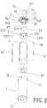
- a lithium ion battery of the present invention includes a shell 1, a locating seat 2, an end cover 3, a battery cell 4, a positive contact 51, a positive plate 52, a negative plate 53, a positive connecting plate 61 and a negative connecting plate 62.
- the shell 1 is a cylinder with an upper opening.
- a contact extending hole 11 is disposed on a center of a bottom plate of the shell 1.
- a mounting hole 21 of the negative plate 53 is arranged at an upper end face of the locating seat 2.
- the locating seat 2 also includes a through hole for positive plate 221 and a through hole for negative plate 222 while the through hole for negative plate 222 communicates with the mounting hole 21.
- An opening of a lower end face of the through hole for positive plate 221 and an opening of a lower end face of the through hole for negative plate 222 are respectively arranged with a positive guide block 2211 and a negative guide block 2221.
- the end cover 3 consists of a central hole 31, a positive plate slot 32 around the central hole 31 and located at an upper end face, a positive plate guide hole 33 penetrating the end cover 3, and a cover edge 34 cooperating with an end surface of the upper opening of the shell 1.
- a lower end face of the end cover 3 is tightly pressed on the negative plate 53 and the locating seat 2.
- the end cover 3 is detachably connected with the upper opening of the shell 1.
- An end part of the battery cell 4 is supporting and cooperating with the positive guide block 2211 and the negative guide block 2221 of the locating seat 2.
- the positive contact 51 extends out from the contact extending hole 11.
- the positive plate 52 is circular and is mounted in the positive plate slot 32 of the end cover 3.
- a positive conductive plate 521 of the positive plate 52 is passed through the positive plate guide hole 33 of the end cover 3, and the through hole for positive plate 221 to cooperate with the positive connecting plate 61.
- the negative plate 53 is arranged in the mounting hole 21 of the locating seat 2 and having a negative conductive plate 531 thereof passed through the through hole for negative plate 222 to cooperate with the negative connecting plate 62.
- the lithium ion battery of the present invention further includes a circular groove 35 on the lower end face of the end cover 3.
- a positioning base 36 is arranged radially outside the circular groove 35.
- the circular groove 35 and the positive plate slot 32 are communicated with each other by the positive plate guide hole 33.
- the upper end face of the locating seat 2 is further disposed with a circular base 23 around the mounting hole 21.
- Both the through hole for positive plate 221 and the through hole for negative plate 222 are located at the circular base 23.
- the through hole for negative plate 222 communicates with the mounting hole 21.
- a lower end of an inner circular wall of the circular groove 35 is leaning against the negative plate 53 while a lower end of an outer circular wall of the circular groove 35 is leaning against the circular base 23.
- the positioning base 36 cooperates with an end part of the locating seat 2 disposed radially outside the circular base 23.
- the lithium ion battery of the present invention further includes two hooks 37 spaced evenly in a circle on the lower end face of the end cover 3.
- Two positioning slots 24 are disposed evenly on a periphery of the locating seat 2 and a wall of the shell 1 is arranged with two locking holes 12.
- a rod part 371 of the hook 37 cooperates with the positioning slot 24 and a hook part 372 of the hook 37 is locked with the locking hole 12.
- At least two projections 13 are disposed evenly in a circle on an outer surface of one end of the shell 1 with the opening.
- An axial locking slot 131 is mounted on the projection 13 and the shell 1.
- Two connecting blocks 341 are disposed evenly on a periphery of the cover edge 34 of the end cover 3.
- Two locking blocks 342 are arranged at a lower part of the cover edge 34 of the end cover 3 and are integrated with the connecting block 341 respectively.
- the projection 13 and the connecting block 341 are fastened with each other to form a positioning block 38 and the locking block 342 is mounted into the locking slot 131.
- a charger consists of a charging circuit board 7, a charging socket 8 and a housing 9.
- the charger further includes a positive spring 101 and a negative spring 102.
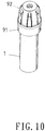
- the housing 9 includes a seat 91 and a cap cover 92.
- An interface 911 is disposed on an upper end of the seat 91 and a curved locking slot 912 is on the interface 911.
- a circular support base 913 is set on an upper part of the interface 911 and a limit base 914 is at a part that connects the circular support base 913 and the interface 911.
- a receiving space 915 is mounted on a lower end face of the seat 91.
- a stopper base 921 and a curved locking protuberance 922 are disposed in a space of the cap cover 92 while the curved locking protuberance 922 cooperates with the curved locking slot 912 of the seat 91.
- the limit base 914 and the stopper base 921 cooperate with each other for stopping.
- An insertion hole 923 is on a top of the cap cover 92.
- the charging circuit board 7 is disposed on the circular support base 913 while the positive spring 101 and the negative spring 102 are arranged in the receiving space 915 and penetrating the receiving space 915 to communicate with the charging circuit board 7.
- the negative spring 102 is located in a space of the positive spring 101.
- the positive spring 101 and the negative spring 102 respectively cooperate with the positive plate 52 and the negative plate 53.
- the charging socket 8 is disposed on the charging circuit board 7 and is corresponding to the insertion hole 923 of the cap cover 92.
- the receiving space 915 of the seat 91 is mounted with a guide positioning slot 916 and the guide positioning slot 916 cooperates with the positioning block 38 of the battery.
- the guide positioning slot 916 cooperates with the positioning block 38 of the battery.
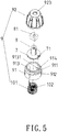
- the charger of the present invention further includes a positioning pin 9131 arranged at the circular support base 913 (with reference to Fig. 5 ).
- a positioning slot 71 is disposed on the charging circuit board 7. The positioning slot 71 cooperates with the positioning pin 9131.
- the charger of the present invention further includes a socket locating seat 81 (with reference to Fig. 5 and Fig. 6 ) disposed on top of the charging socket 8.
- a positioning blind hole 924 is mounted on the insertion hole 923 of the cap cover 92.
- the socket locating seat 81 cooperates with the positioning blind hole 924 for positioning.
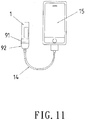
- the charger of the present invention further includes an adaptor cable 14.
- One end of the adaptor cable 14 is passed through the insertion hole 923 of the cap cover 92 to cooperate with the charging socket 8 (with reference to Fig. 5 ) while the other end thereof cooperates with a charging socket of a mobile phone 15.
- the lithium ion battery and the charger are assembled.
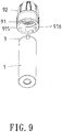
- the shell 1 of the lithium ion battery is mounted into the seat 91 of the charger.
- the positioning block 38 is first moved along the guide positioning slot 916.
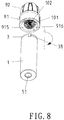
- the shell 11 is rotated counterclockwise as shown in Fig. 8 .
- the assembly of the lithium ion battery and the charger is completed.
- the positive and negative springs 101, 102 are respectively connected to and cooperated with the positive plate 52 and the negative plate 53.
Landscapes
- Chemical & Material Sciences (AREA)
- Chemical Kinetics & Catalysis (AREA)
- Electrochemistry (AREA)
- General Chemical & Material Sciences (AREA)
- Engineering & Computer Science (AREA)
- Manufacturing & Machinery (AREA)
- Power Engineering (AREA)
- Materials Engineering (AREA)
- Battery Mounting, Suspending (AREA)
- Secondary Cells (AREA)
- Charge And Discharge Circuits For Batteries Or The Like (AREA)
- Connection Of Batteries Or Terminals (AREA)
Claims (10)
- Une batterie comprenant une coque (1), un siège de positionnement (2), un couvercle d'extrémité (3), une cellule de batterie (4), un contact positif (51), une plaque positive (52), une plaque négative (53), une plaque de connexion positive (61) et une plaque de connexion négative (62) ;la coque (1) étant un cylindre ayant une ouverture supérieure et un trou (11) d'extension de contact sur un centre d'une plaque inférieure de la coque (1) ;une face d'extrémité supérieure du siège de positionnement (2) est agencée avec un trou de montage (21) de la plaque négative (53) ; le siège de positionnement (2) comprend en outre un trou traversant (221) pour la plaque positive et un trou traversant (222) pour la plaque négative, le trou traversant (222) pour la plaque négative communiquant avec le trou de montage (21) ;le couvercle d'extrémité (3) est monté avec un trou central (31) et une face d'extrémité supérieure de celui-ci est agencée avec une fente (32) de plaque positive autour du trou central (31) ; un trou de guidage (33) de plaque positive pénètre dans le couvercle d'extrémité (3) ; une face d'extrémité inférieure du couvercle d'extrémité (3) est pressée étroitement contre la plaque négative (53) et contre le siège de positionnement (2) ; le couvercle d'extrémité (3) est relié de manière détachable à l'ouverture supérieure de la coque (1) et un bord (34) de couvercle du couvercle d'extrémité (3) coopère avec une surface d'extrémité de l'ouverture supérieure de la coque (1) ;la plaque positive (52) est circulaire et est montée dans la fente (32) de plaque positive du couvercle d'extrémité (3) ;caractérisée en ce que:la batterie est une batterie au lithium-ion ;une face d'extrémité inférieure du trou traversant (221) pour plaque positive et une face d'extrémité inférieure du trou traversant (222) pour plaque négative sont respectivement agencées avec un bloc de guidage positif (2211) et un bloc de guidage négatif (2221) ; le bloc de guidage positif (2211) et le bloc de guidage négatif (2221) sont supportés par une partie d'extrémité de la cellule de batterie (4) et sont en coopération avec celle-ci ;une plaque conductrice positive (521) de la plaque positive (52) est passée à travers le trou de guidage (33) de plaque positive du couvercle d'extrémité (3) et le trou traversant (221) pour plaque positive afin de coopérer avec la plaque de connexion positive (61) ;la plaque négative (53) est disposée dans le trou de montage (21) du siège de positionnement (2) et a une plaque conductrice négative (531) engagée au travers du trou traversant (222) pour plaque négative afin de coopérer avec la plaque de connexion négative (62) ; le contact positif (51) s'étend à partir du trou (11) d'extension de contact.
- Le dispositif selon la revendication 1, dans lequel la face d'extrémité inférieure du couvercle d'extrémité (3) présente une rainure circulaire (35) tandis qu'une embase de positionnement (36) est aménagée radialement à l'extérieur de la rainure circulaire (35) ; la rainure circulaire (35) et la fente (32) de plaque positive sont en communication l'une avec l'autre par le trou de guidage (33) de plaque positif ; la face d'extrémité supérieure du siège de positionnement (2) présente en outre une embase circulaire (23) autour du trou de montage (21) ; le trou traversant (221) pour plaque positive et le trou traversant (222) pour plaque négative sont montés sur l'embase circulaire (23) ; le trou traversant (222) pour plaque négative communique avec le trou de montage (21) ; une extrémité inférieure d'une paroi circulaire intérieure de la rainure circulaire (35) s'appuie contre la plaque négative (53) tandis qu'une extrémité inférieure d'une paroi circulaire extérieure de la rainure circulaire (35) coopère avec une partie d'extrémité du siège de positionnement (2) disposés radialement à l'extérieur de l'embase circulaire (23).
- Le dispositif selon la revendication 1, dans lequel la face d'extrémité inférieure du couvercle d'extrémité (3) est agencée avec deux crochets (37) espacés uniformément dans un cercle de celui-ci ; une périphérie du siège de positionnement (2) présente avec deux fentes de positionnement (24) aménagées de manière homogène tandis qu'une paroi de la coque (1) est agencée avec des trous de verrouillage (12) ; une partie de tige (371) du crochet coopère avec la fente de positionnement (24) et une partie en crochet (372) du crochet est verrouillée avec le trou de verrouillage (12).
- Le dispositif selon la revendication 1, dans lequel une surface extérieure d'une extrémité de la coque (1) ayant l'ouverture présente au moins deux saillies (13) aménagées de façon uniforme dans un cercle de celle-ci ; une fente de verrouillage axial (131) est située sur la saillie (13) et la coque (1) ; une périphérie du bord de couvercle (34) du couvercle d'extrémité (3) est disposée uniformément avec au moins deux blocs de connexion (341) ; une partie inférieure du bord de couvercle (34) du couvercle d'extrémité (3) est agencée avec des blocs de verrouillage (342) qui sont intégrés aux blocs de connexion (341) ; la projection (13) et le bloc de connexion (341) sont fixés l'un avec l'autre pour former un bloc de positionnement (38) ; le bloc de verrouillage (342) est monté dans la fente de verrouillage (131).
- Le dispositif selon la revendication 4, dans lequel deux crochets (37) sont espacés uniformément dans un cercle situé sur la face d'extrémité inférieure du couvercle d'extrémité (3) et deux fentes de positionnement (24) sont disposées de manière uniforme sur une périphérie du siège de positionnement (2) ; une paroi du cylindre est agencée avec deux trous de verrouillage (12) ; une partie de tige (371) du crochet coopère avec la fente de positionnement (24) et une partie en crochet (372) du crochet est verrouillée avec le trou de verrouillage (12).
- Un chargeur de la batterie au lithium-ion tel que revendiqué de la revendication 1 à la revendication 5, caractérisé en ce qu'il comprend une carte de circuit de charge (7), une prise de charge (8) et un boîtier (9) ; le chargeur comprend en outre un ressort positif (101) et un ressort négatif (102) ;le boîtier (9) comprend un siège (91) et un couvercle formant capuchon (92) ;une interface (911) est disposée sur une extrémité supérieure du siège (91) et une fente de verrouillage courbe (912) est présente sur l'interface (911) ; une embase de support circulaire (913) est placée sur une partie supérieure de l'interface (911) et une embase de limitation (914) se trouve sur une partie qui relie l'embase de support circulaire (913) et l'interface (911) ; un espace de réception (915) est monté sur une face d'extrémité inférieure du siège (91) et le siège (91) est relié à la batterie ;un trou d'insertion (923) se trouve au-dessus du couvercle formant capuchon (92) tandis qu'une embase de butée (921) et une protubérance de verrouillage courbe (922) sont disposées dans un espace du couvercle formant capuchon (92) ; la protubérance de verrouillage incurvée (922) du couvercle formant capuchon (92) coopère avec la fente de verrouillage incurvée (912) du siège (91) ; l'embase de limitation (914) et l'embase de butée (921) coopèrent l'une avec l'autre pour arrêter ;la carte de circuit de charge (7) est disposée sur l'embase de support circulaire (913) ;le ressort positif (101) et le ressort négatif (102) sont agencés dans l'espace de réception (915) et passent à travers l'espace de réception (915) pour être connectés à la carte de circuit de charge (7) ; le ressort négatif (102) est situé dans un espace du ressort positif (101) ; le ressort positif (101) et le ressort négatif (102) coopèrent avec la plaque positive (52) et la plaque négative (53), respectivement ;la prise de charge (8) est agencée sur la carte de circuit de charge (7) et est en correspondance avec le trou d'insertion (923) du couvercle formant capuchon (92) ;l'espace de réception (915) du siège (91) est monté avec une fente de positionnement de guide (916) et la fente de positionnement de guide (916) coopère avec le bloc de positionnement (38) sur la coque (1) de la batterie.
- Le dispositif selon la revendication 6, dans lequel l'espace de réception (915) du siège (91) est monté avec la fente de positionnement de guide (916) et une surface extérieure d'une extrémité de la coque (1) ayant l'ouverture présente au moins deux saillies (13) disposées uniformément dans un cercle de celle-ci ; une fente de verrouillage axial (131) est située sur la saillie (13) et la coque (1) ; une périphérie du bord de couvercle (34) du couvercle d'extrémité (3) présente au moins deux blocs de connexion (341) disposés uniformément ; une partie inférieure du bord de couvercle (34) du couvercle d'extrémité (3) est agencée avec des blocs de verrouillage (342) qui sont intégrés aux blocs de connexion (341) ; le bloc de verrouillage (342) est monté dans la fente de verrouillage (131) tandis que la saillie (13) et le bloc de connexion (341) sont fixés l'un à l'autre pour former un bloc de positionnement (38), et le bloc de positionnement (38) coopère avec la fente de positionnement de guide (916).
- Le dispositif selon la revendication 6, dans lequel une broche de positionnement (9131) est agencée au niveau de l'embase de support circulaire (913) et une fente de positionnement (71) est disposée sur la carte de circuit de charge (7) ; la fente de positionnement (71) coopère avec la broche de positionnement (9131).
- Le dispositif selon la revendication 6, dans lequel le chargeur comprend en outre un siège de positionnement de prise (81) qui est disposé au-dessus de la prise de charge (8) ; un trou borgne de positionnement (924) est monté sur le trou d'insertion (923) du couvercle formant capuchon (92) et le siège de positionnement de prise (81) coopère avec le trou borgne de positionnement (924) pour le positionnement.
- Le dispositif selon la revendication 6, dans lequel le chargeur comprend en outre un câble adaptateur (14) ; une extrémité du câble adaptateur (14) coopère avec la prise de charge (8) tandis que l'autre extrémité de celle-ci coopère avec une prise de charge d'appareils avec des batteries rechargeables.
Applications Claiming Priority (2)
| Application Number | Priority Date | Filing Date | Title |
|---|---|---|---|
| TW099133027A TWI416781B (zh) | 2010-09-29 | 2010-09-29 | 鋰離子電池及應用該鋰離子電池的充電器 |
| PCT/CN2010/078733 WO2012065289A1 (fr) | 2010-09-29 | 2010-11-15 | Pile au lithium-ion et chargeur associé |
Publications (3)
| Publication Number | Publication Date |
|---|---|
| EP2642576A1 EP2642576A1 (fr) | 2013-09-25 |
| EP2642576A4 EP2642576A4 (fr) | 2015-03-04 |
| EP2642576B1 true EP2642576B1 (fr) | 2017-11-15 |
Family
ID=51845603
Family Applications (1)
| Application Number | Title | Priority Date | Filing Date |
|---|---|---|---|
| EP10859653.7A Not-in-force EP2642576B1 (fr) | 2010-09-29 | 2010-11-15 | Pile au lithium-ion et chargeur associé |
Country Status (8)
| Country | Link |
|---|---|
| US (1) | US9054346B2 (fr) |
| EP (1) | EP2642576B1 (fr) |
| JP (1) | JP5528638B2 (fr) |
| CN (2) | CN101944633B (fr) |
| AU (1) | AU2010364313B2 (fr) |
| CA (1) | CA2817386C (fr) |
| TW (1) | TWI416781B (fr) |
| WO (1) | WO2012065289A1 (fr) |
Cited By (1)
| Publication number | Priority date | Publication date | Assignee | Title |
|---|---|---|---|---|
| DE102021127935A1 (de) | 2021-10-27 | 2023-04-27 | Bayerische Motoren Werke Aktiengesellschaft | Batteriezelle, Energiespeicher und Verfahren zur Entlüftung einer Batteriezelle |
Families Citing this family (33)
| Publication number | Priority date | Publication date | Assignee | Title |
|---|---|---|---|---|
| CN101944633B (zh) * | 2010-09-29 | 2012-11-07 | 广东正飞移动照明有限公司 | 一种锂离子电池及应用该锂离子电池的充电器 |
| CN102013467B (zh) * | 2010-09-30 | 2013-01-02 | 广东正飞移动照明有限公司 | 一种多极电池供电装置及应用多极电池供电装置的手电筒 |
| TWI450470B (zh) * | 2011-02-18 | 2014-08-21 | 廣東正飛移動照明有限公司 | 移動充電器 |
| AU2015271930B2 (en) * | 2011-03-09 | 2016-12-15 | Guangdong Jetfast Portable Lighting Co., Ltd. | Mobile charger |
| CN102734755B (zh) * | 2011-03-31 | 2015-08-05 | 海洋王照明科技股份有限公司 | 导电结构及含有该导电结构的手电筒 |
| TW201331756A (zh) * | 2012-01-18 | 2013-08-01 | 廣東正飛移動照明有限公司 | Usb充電控制器 |
| CN103825319B (zh) * | 2013-12-09 | 2017-10-24 | 曾令文 | 一种充电器 |
| CN203723445U (zh) * | 2014-01-22 | 2014-07-23 | 刘秋明 | 一种电池杆及电子烟 |
| TWI493776B (zh) * | 2014-03-14 | 2015-07-21 | 廣東正飛移動照明有限公司 | 五極電池盒結構 |
| CN108232055B (zh) * | 2016-12-16 | 2020-08-14 | 航天科工惯性技术有限公司 | 地下钻孔内监测仪用电池容纳装置、供电装置及监测仪 |
| EP3382943B1 (fr) | 2017-03-28 | 2020-09-02 | Intraway R&D S.A. | Procédé et système de gestion d'une infrastructure de fournisseur de services |
| KR102203249B1 (ko) | 2017-10-10 | 2021-01-13 | 주식회사 엘지화학 | 접속 캡을 구비한 원통형 전지셀 |
| CN107859900A (zh) * | 2017-11-02 | 2018-03-30 | 倪梁程 | 一种多人合用的野外多功能手电 |
| CN109755988B (zh) * | 2017-11-08 | 2025-02-18 | 惠州志顺电子实业有限公司 | 充电装置及其充电方法 |
| CN108678914B (zh) * | 2018-05-15 | 2020-06-09 | 杭州指挥通讯设备有限公司 | 一种用于核能通讯检修电话的多功能储能装置 |
| CN109040877B (zh) * | 2018-09-04 | 2023-07-14 | 东莞精恒电子有限公司 | 一种可旋转音柱的连接结构及其使用方法 |
| CN109713749A (zh) * | 2018-12-28 | 2019-05-03 | 华勤通讯技术有限公司 | 可穿戴设备 |
| CN109560318B (zh) * | 2018-12-29 | 2024-01-26 | 桂林市啄木鸟医疗器械有限公司 | 可充电电池以及热熔牙胶笔 |
| CN109768212B (zh) * | 2019-01-03 | 2022-05-03 | 博科能源系统(深圳)有限公司 | 一种电池 |
| CN109980269A (zh) * | 2019-04-30 | 2019-07-05 | 深圳市兴鸿瑞科技有限公司 | 可充电电池及其充电器 |
| CN111432581B (zh) * | 2020-05-14 | 2025-03-07 | 成都肯保捷旭阳新能源电器有限公司 | 一种新型农用拖拉机中央电器控制盒 |
| CN111864171B (zh) * | 2020-08-26 | 2025-06-06 | 重庆北斗捷安新能源科技有限公司 | 一种电池连接用快拆座 |
| CN111864865A (zh) * | 2020-08-26 | 2020-10-30 | 东莞市佐奇电子有限公司 | 可产生天然负离子的车载充电器 |
| CN115241593B (zh) * | 2021-01-15 | 2024-05-24 | 深圳市九方电子科技有限公司 | 一种便于更换的无人机电池仓 |
| CN113097633B (zh) * | 2021-03-31 | 2025-08-12 | 蜂巢能源科技(无锡)有限公司 | 一种电池及其组装工艺 |
| CN113314799B (zh) * | 2021-06-07 | 2022-09-27 | 江苏天辉锂电池有限公司 | 一种锂电池 |
| CN113488728B (zh) * | 2021-07-02 | 2022-06-28 | 横店集团东磁股份有限公司 | 一种圆柱形电池 |
| US11876237B2 (en) * | 2021-07-05 | 2024-01-16 | Xiaofeng Zhang | Cylindrical waterproof battery box |
| USD1079601S1 (en) * | 2022-07-18 | 2025-06-17 | Xiamen Hithium Energy Storage Technology Co., Ltd. | Cylindrical battery |
| USD1079600S1 (en) * | 2022-08-29 | 2025-06-17 | Xiamen Hithium Energy Storage Technology Co., Ltd. | Cylindrical battery |
| CN221379671U (zh) * | 2023-11-23 | 2024-07-19 | 中山普纳斯能源科技有限公司 | 圆柱型锂离子电池 |
| CN118676546B (zh) * | 2024-06-28 | 2025-03-07 | 智泰新能源(东台)有限公司 | 一种电池负极结构及其锂离子电池组 |
| CN118763181B (zh) * | 2024-07-18 | 2025-03-07 | 智泰新能源(东台)有限公司 | 一种具有保护体系的锂离子电池组 |
Family Cites Families (20)
| Publication number | Priority date | Publication date | Assignee | Title |
|---|---|---|---|---|
| EP0144569B1 (fr) * | 1979-10-22 | 1991-01-23 | Hardigg Industries, Incorporated | Machine pour souder les bacs d'acculmulateurs |
| DE4213791A1 (de) * | 1991-04-26 | 1992-10-29 | Amphenol Tuchel Elect | Geschirmter steckverbinder |
| JP3060824B2 (ja) * | 1994-04-11 | 2000-07-10 | 松下電器産業株式会社 | 電 池 |
| US6164490A (en) * | 1999-05-03 | 2000-12-26 | Northeast Iowa Rehabilitation Agency | Storage and dispensing package for batteries and other objects |
| TW447153B (en) * | 1999-06-07 | 2001-07-21 | Matsushita Electric Industrial Co Ltd | Storage battery |
| US6359418B1 (en) * | 1999-06-18 | 2002-03-19 | Leupold & Stevens, Inc. | Replaceable battery module |
| US6844110B2 (en) * | 2000-05-24 | 2005-01-18 | Ngk Insulators, Ltd. | Lithium secondary cell and assembly thereof |
| CA2401915C (fr) * | 2001-09-11 | 2007-01-09 | Matsushita Electric Industrial Co., Ltd. | Pile a combustible a electrolyte polymere |
| JP4359100B2 (ja) * | 2003-08-04 | 2009-11-04 | 三洋電機株式会社 | 円筒型アルカリ蓄電池 |
| CN2663793Y (zh) * | 2003-08-22 | 2004-12-15 | 袁仕杰 | 笔形手持聚光灯和专用充电器插座 |
| US7220013B2 (en) * | 2003-12-19 | 2007-05-22 | Streamlight, Inc. | Rechargeable flashlight and battery assembly for single-handed intermittent and continuous operation |
| EP1714334B1 (fr) * | 2004-01-28 | 2017-11-08 | Lg Chem, Ltd. | Accumulateur a structure de type assemblage |
| KR100614372B1 (ko) * | 2004-06-25 | 2006-08-21 | 삼성에스디아이 주식회사 | 원통형 리튬 이차 전지 및 그의 제조 방법 |
| WO2006109549A1 (fr) * | 2005-04-06 | 2006-10-19 | Matsushita Electric Industrial Co., Ltd. | Accumulateur au plomb |
| JP2007280831A (ja) * | 2006-04-10 | 2007-10-25 | Matsushita Electric Ind Co Ltd | 電源装置 |
| CN201017947Y (zh) * | 2007-03-09 | 2008-02-06 | 刘允钊 | 连体式电芯 |
| US7785723B2 (en) * | 2007-07-05 | 2010-08-31 | Yun-Zhao Liu | Battery device with plural joined-together batteries |
| CN201117688Y (zh) * | 2007-10-29 | 2008-09-17 | 刘允钊 | 电芯 |
| JP5065353B2 (ja) * | 2009-09-16 | 2012-10-31 | 廣東正飛移動照明有限公司 | 充放電可能な懐中電灯 |
| CN101944633B (zh) * | 2010-09-29 | 2012-11-07 | 广东正飞移动照明有限公司 | 一种锂离子电池及应用该锂离子电池的充电器 |
-
2010
- 2010-08-20 CN CN2010102597292A patent/CN101944633B/zh not_active Expired - Fee Related
- 2010-08-20 CN CN2010205008774U patent/CN201781032U/zh not_active Expired - Fee Related
- 2010-09-29 TW TW099133027A patent/TWI416781B/zh not_active IP Right Cessation
- 2010-11-15 JP JP2013538024A patent/JP5528638B2/ja not_active Expired - Fee Related
- 2010-11-15 WO PCT/CN2010/078733 patent/WO2012065289A1/fr not_active Ceased
- 2010-11-15 AU AU2010364313A patent/AU2010364313B2/en not_active Ceased
- 2010-11-15 CA CA2817386A patent/CA2817386C/fr not_active Expired - Fee Related
- 2010-11-15 EP EP10859653.7A patent/EP2642576B1/fr not_active Not-in-force
- 2010-11-15 US US13/885,036 patent/US9054346B2/en not_active Expired - Fee Related
Non-Patent Citations (1)
| Title |
|---|
| None * |
Cited By (1)
| Publication number | Priority date | Publication date | Assignee | Title |
|---|---|---|---|---|
| DE102021127935A1 (de) | 2021-10-27 | 2023-04-27 | Bayerische Motoren Werke Aktiengesellschaft | Batteriezelle, Energiespeicher und Verfahren zur Entlüftung einer Batteriezelle |
Also Published As
| Publication number | Publication date |
|---|---|
| CN201781032U (zh) | 2011-03-30 |
| US9054346B2 (en) | 2015-06-09 |
| EP2642576A4 (fr) | 2015-03-04 |
| AU2010364313B2 (en) | 2015-06-11 |
| TW201214842A (en) | 2012-04-01 |
| CN101944633A (zh) | 2011-01-12 |
| CN101944633B (zh) | 2012-11-07 |
| CA2817386A1 (fr) | 2012-05-24 |
| CA2817386C (fr) | 2016-08-02 |
| AU2010364313A1 (en) | 2013-06-06 |
| TWI416781B (zh) | 2013-11-21 |
| US20130236774A1 (en) | 2013-09-12 |
| JP5528638B2 (ja) | 2014-06-25 |
| WO2012065289A1 (fr) | 2012-05-24 |
| EP2642576A1 (fr) | 2013-09-25 |
| JP2014502008A (ja) | 2014-01-23 |
Similar Documents
| Publication | Publication Date | Title |
|---|---|---|
| AU2010364313B2 (en) | Lithium ion battery and charger thereof | |
| US7457649B1 (en) | Headset charging station | |
| CN114156983A (zh) | 一种通用移动电源 | |
| CN214707215U (zh) | 磁吸式充电设备 | |
| KR101437948B1 (ko) | 축전지가 구비된 휴대용 충전기 | |
| CN204481506U (zh) | 车载手机保护与充电装置 | |
| CN221531012U (zh) | 一种充电宝及无线充电装置 | |
| CN209748765U (zh) | 一种与蓝牙耳机配套使用的充电收纳盒 | |
| TWM557932U (zh) | 行動充電裝置及其電源供應組件 | |
| EP3214703B1 (fr) | Ensemble comprenant un ensemble de ligne électrique et un dispositif électronique | |
| US9673649B2 (en) | Charger for lithium ion battery | |
| BR112014008740B1 (pt) | Base suporte de terminal de informação portátil e telefone de mesa | |
| CN217903304U (zh) | 一种电池固定结构、音频设备、照明设备及通信设备 | |
| CN216672657U (zh) | 一种组合式移动电源 | |
| KR101955772B1 (ko) | 휴대폰과 연결 가능한 결합부재를 갖는 보조배터리 | |
| CN211428933U (zh) | 一种多功能座充 | |
| CN216699590U (zh) | 电源设备和运载车辆 | |
| CN210608618U (zh) | 一种简易的充电座 | |
| CN219717951U (zh) | 一种无线充电主体件、配件和组件 | |
| CN223391124U (zh) | 一种多功能无线充电器 | |
| CN222896778U (zh) | 外置电池 | |
| CN219181648U (zh) | 一种保护壳、无线耳机及终端 | |
| CN205178562U (zh) | 一种多功能微型充电器 | |
| KR20150106576A (ko) | 휴대폰 거치장치 | |
| CN217985361U (zh) | 耳机充电装置以及无线耳机充电盒 |
Legal Events
| Date | Code | Title | Description |
|---|---|---|---|
| PUAI | Public reference made under article 153(3) epc to a published international application that has entered the european phase |
Free format text: ORIGINAL CODE: 0009012 |
|
| 17P | Request for examination filed |
Effective date: 20130524 |
|
| AK | Designated contracting states |
Kind code of ref document: A1 Designated state(s): AL AT BE BG CH CY CZ DE DK EE ES FI FR GB GR HR HU IE IS IT LI LT LU LV MC MK MT NL NO PL PT RO RS SE SI SK SM TR |
|
| DAX | Request for extension of the european patent (deleted) | ||
| A4 | Supplementary search report drawn up and despatched |
Effective date: 20150130 |
|
| RIC1 | Information provided on ipc code assigned before grant |
Ipc: H01M 2/10 20060101ALI20150126BHEP Ipc: H01M 2/04 20060101ALI20150126BHEP Ipc: H01M 10/0525 20100101AFI20150126BHEP Ipc: H01R 13/15 20060101ALI20150126BHEP Ipc: H01M 10/46 20060101ALI20150126BHEP Ipc: H01R 13/24 20060101ALI20150126BHEP Ipc: H01M 2/20 20060101ALI20150126BHEP Ipc: H01R 13/213 20060101ALI20150126BHEP Ipc: H01M 2/30 20060101ALI20150126BHEP Ipc: H01R 24/38 20110101ALI20150126BHEP Ipc: H02J 7/00 20060101ALI20150126BHEP Ipc: H01M 2/02 20060101ALI20150126BHEP Ipc: H01M 10/052 20100101ALI20150126BHEP |
|
| 17Q | First examination report despatched |
Effective date: 20160712 |
|
| GRAP | Despatch of communication of intention to grant a patent |
Free format text: ORIGINAL CODE: EPIDOSNIGR1 |
|
| RIC1 | Information provided on ipc code assigned before grant |
Ipc: H01R 24/38 20110101ALI20170615BHEP Ipc: H01M 2/20 20060101ALI20170615BHEP Ipc: H01M 2/30 20060101ALI20170615BHEP Ipc: H01M 2/10 20060101ALI20170615BHEP Ipc: H01M 10/0525 20100101AFI20170615BHEP Ipc: H01M 2/02 20060101ALI20170615BHEP Ipc: H01M 10/46 20060101ALI20170615BHEP Ipc: H01R 13/15 20060101ALI20170615BHEP Ipc: H01R 13/213 20060101ALI20170615BHEP Ipc: H01R 13/24 20060101ALI20170615BHEP Ipc: H02J 7/00 20060101ALI20170615BHEP |
|
| INTG | Intention to grant announced |
Effective date: 20170628 |
|
| GRAS | Grant fee paid |
Free format text: ORIGINAL CODE: EPIDOSNIGR3 |
|
| GRAA | (expected) grant |
Free format text: ORIGINAL CODE: 0009210 |
|
| AK | Designated contracting states |
Kind code of ref document: B1 Designated state(s): AL AT BE BG CH CY CZ DE DK EE ES FI FR GB GR HR HU IE IS IT LI LT LU LV MC MK MT NL NO PL PT RO RS SE SI SK SM TR |
|
| REG | Reference to a national code |
Ref country code: CH Ref legal event code: EP Ref country code: GB Ref legal event code: FG4D Ref country code: AT Ref legal event code: REF Ref document number: 947116 Country of ref document: AT Kind code of ref document: T Effective date: 20171115 |
|
| REG | Reference to a national code |
Ref country code: IE Ref legal event code: FG4D |
|
| REG | Reference to a national code |
Ref country code: FR Ref legal event code: PLFP Year of fee payment: 8 |
|
| REG | Reference to a national code |
Ref country code: DE Ref legal event code: R096 Ref document number: 602010046803 Country of ref document: DE |
|
| REG | Reference to a national code |
Ref country code: NL Ref legal event code: MP Effective date: 20171115 |
|
| REG | Reference to a national code |
Ref country code: LT Ref legal event code: MG4D |
|
| REG | Reference to a national code |
Ref country code: AT Ref legal event code: MK05 Ref document number: 947116 Country of ref document: AT Kind code of ref document: T Effective date: 20171115 |
|
| PG25 | Lapsed in a contracting state [announced via postgrant information from national office to epo] |
Ref country code: NO Free format text: LAPSE BECAUSE OF FAILURE TO SUBMIT A TRANSLATION OF THE DESCRIPTION OR TO PAY THE FEE WITHIN THE PRESCRIBED TIME-LIMIT Effective date: 20180215 Ref country code: NL Free format text: LAPSE BECAUSE OF FAILURE TO SUBMIT A TRANSLATION OF THE DESCRIPTION OR TO PAY THE FEE WITHIN THE PRESCRIBED TIME-LIMIT Effective date: 20171115 Ref country code: FI Free format text: LAPSE BECAUSE OF FAILURE TO SUBMIT A TRANSLATION OF THE DESCRIPTION OR TO PAY THE FEE WITHIN THE PRESCRIBED TIME-LIMIT Effective date: 20171115 Ref country code: LT Free format text: LAPSE BECAUSE OF FAILURE TO SUBMIT A TRANSLATION OF THE DESCRIPTION OR TO PAY THE FEE WITHIN THE PRESCRIBED TIME-LIMIT Effective date: 20171115 Ref country code: ES Free format text: LAPSE BECAUSE OF FAILURE TO SUBMIT A TRANSLATION OF THE DESCRIPTION OR TO PAY THE FEE WITHIN THE PRESCRIBED TIME-LIMIT Effective date: 20171115 Ref country code: SE Free format text: LAPSE BECAUSE OF FAILURE TO SUBMIT A TRANSLATION OF THE DESCRIPTION OR TO PAY THE FEE WITHIN THE PRESCRIBED TIME-LIMIT Effective date: 20171115 |
|
| PG25 | Lapsed in a contracting state [announced via postgrant information from national office to epo] |
Ref country code: HR Free format text: LAPSE BECAUSE OF FAILURE TO SUBMIT A TRANSLATION OF THE DESCRIPTION OR TO PAY THE FEE WITHIN THE PRESCRIBED TIME-LIMIT Effective date: 20171115 Ref country code: RS Free format text: LAPSE BECAUSE OF FAILURE TO SUBMIT A TRANSLATION OF THE DESCRIPTION OR TO PAY THE FEE WITHIN THE PRESCRIBED TIME-LIMIT Effective date: 20171115 Ref country code: BG Free format text: LAPSE BECAUSE OF FAILURE TO SUBMIT A TRANSLATION OF THE DESCRIPTION OR TO PAY THE FEE WITHIN THE PRESCRIBED TIME-LIMIT Effective date: 20180215 Ref country code: GR Free format text: LAPSE BECAUSE OF FAILURE TO SUBMIT A TRANSLATION OF THE DESCRIPTION OR TO PAY THE FEE WITHIN THE PRESCRIBED TIME-LIMIT Effective date: 20180216 Ref country code: AT Free format text: LAPSE BECAUSE OF FAILURE TO SUBMIT A TRANSLATION OF THE DESCRIPTION OR TO PAY THE FEE WITHIN THE PRESCRIBED TIME-LIMIT Effective date: 20171115 Ref country code: LV Free format text: LAPSE BECAUSE OF FAILURE TO SUBMIT A TRANSLATION OF THE DESCRIPTION OR TO PAY THE FEE WITHIN THE PRESCRIBED TIME-LIMIT Effective date: 20171115 |
|
| PG25 | Lapsed in a contracting state [announced via postgrant information from national office to epo] |
Ref country code: LI Free format text: LAPSE BECAUSE OF NON-PAYMENT OF DUE FEES Effective date: 20171130 Ref country code: SK Free format text: LAPSE BECAUSE OF FAILURE TO SUBMIT A TRANSLATION OF THE DESCRIPTION OR TO PAY THE FEE WITHIN THE PRESCRIBED TIME-LIMIT Effective date: 20171115 Ref country code: DK Free format text: LAPSE BECAUSE OF FAILURE TO SUBMIT A TRANSLATION OF THE DESCRIPTION OR TO PAY THE FEE WITHIN THE PRESCRIBED TIME-LIMIT Effective date: 20171115 Ref country code: CY Free format text: LAPSE BECAUSE OF FAILURE TO SUBMIT A TRANSLATION OF THE DESCRIPTION OR TO PAY THE FEE WITHIN THE PRESCRIBED TIME-LIMIT Effective date: 20171115 Ref country code: EE Free format text: LAPSE BECAUSE OF FAILURE TO SUBMIT A TRANSLATION OF THE DESCRIPTION OR TO PAY THE FEE WITHIN THE PRESCRIBED TIME-LIMIT Effective date: 20171115 Ref country code: CH Free format text: LAPSE BECAUSE OF NON-PAYMENT OF DUE FEES Effective date: 20171130 Ref country code: CZ Free format text: LAPSE BECAUSE OF FAILURE TO SUBMIT A TRANSLATION OF THE DESCRIPTION OR TO PAY THE FEE WITHIN THE PRESCRIBED TIME-LIMIT Effective date: 20171115 |
|
| REG | Reference to a national code |
Ref country code: DE Ref legal event code: R097 Ref document number: 602010046803 Country of ref document: DE |
|
| PG25 | Lapsed in a contracting state [announced via postgrant information from national office to epo] |
Ref country code: LU Free format text: LAPSE BECAUSE OF NON-PAYMENT OF DUE FEES Effective date: 20171115 Ref country code: SM Free format text: LAPSE BECAUSE OF FAILURE TO SUBMIT A TRANSLATION OF THE DESCRIPTION OR TO PAY THE FEE WITHIN THE PRESCRIBED TIME-LIMIT Effective date: 20171115 Ref country code: PL Free format text: LAPSE BECAUSE OF FAILURE TO SUBMIT A TRANSLATION OF THE DESCRIPTION OR TO PAY THE FEE WITHIN THE PRESCRIBED TIME-LIMIT Effective date: 20171115 Ref country code: RO Free format text: LAPSE BECAUSE OF FAILURE TO SUBMIT A TRANSLATION OF THE DESCRIPTION OR TO PAY THE FEE WITHIN THE PRESCRIBED TIME-LIMIT Effective date: 20171115 |
|
| REG | Reference to a national code |
Ref country code: BE Ref legal event code: MM Effective date: 20171130 |
|
| REG | Reference to a national code |
Ref country code: IE Ref legal event code: MM4A |
|
| PLBE | No opposition filed within time limit |
Free format text: ORIGINAL CODE: 0009261 |
|
| STAA | Information on the status of an ep patent application or granted ep patent |
Free format text: STATUS: NO OPPOSITION FILED WITHIN TIME LIMIT |
|
| PG25 | Lapsed in a contracting state [announced via postgrant information from national office to epo] |
Ref country code: MT Free format text: LAPSE BECAUSE OF NON-PAYMENT OF DUE FEES Effective date: 20171115 |
|
| 26N | No opposition filed |
Effective date: 20180817 |
|
| PG25 | Lapsed in a contracting state [announced via postgrant information from national office to epo] |
Ref country code: IE Free format text: LAPSE BECAUSE OF NON-PAYMENT OF DUE FEES Effective date: 20171115 |
|
| PG25 | Lapsed in a contracting state [announced via postgrant information from national office to epo] |
Ref country code: SI Free format text: LAPSE BECAUSE OF FAILURE TO SUBMIT A TRANSLATION OF THE DESCRIPTION OR TO PAY THE FEE WITHIN THE PRESCRIBED TIME-LIMIT Effective date: 20171115 Ref country code: BE Free format text: LAPSE BECAUSE OF NON-PAYMENT OF DUE FEES Effective date: 20171130 |
|
| PG25 | Lapsed in a contracting state [announced via postgrant information from national office to epo] |
Ref country code: HU Free format text: LAPSE BECAUSE OF FAILURE TO SUBMIT A TRANSLATION OF THE DESCRIPTION OR TO PAY THE FEE WITHIN THE PRESCRIBED TIME-LIMIT; INVALID AB INITIO Effective date: 20101115 Ref country code: MC Free format text: LAPSE BECAUSE OF FAILURE TO SUBMIT A TRANSLATION OF THE DESCRIPTION OR TO PAY THE FEE WITHIN THE PRESCRIBED TIME-LIMIT Effective date: 20171115 |
|
| PG25 | Lapsed in a contracting state [announced via postgrant information from national office to epo] |
Ref country code: MK Free format text: LAPSE BECAUSE OF FAILURE TO SUBMIT A TRANSLATION OF THE DESCRIPTION OR TO PAY THE FEE WITHIN THE PRESCRIBED TIME-LIMIT Effective date: 20171115 |
|
| PGFP | Annual fee paid to national office [announced via postgrant information from national office to epo] |
Ref country code: DE Payment date: 20191122 Year of fee payment: 10 |
|
| PGFP | Annual fee paid to national office [announced via postgrant information from national office to epo] |
Ref country code: IT Payment date: 20191120 Year of fee payment: 10 Ref country code: FR Payment date: 20191129 Year of fee payment: 10 |
|
| PG25 | Lapsed in a contracting state [announced via postgrant information from national office to epo] |
Ref country code: TR Free format text: LAPSE BECAUSE OF FAILURE TO SUBMIT A TRANSLATION OF THE DESCRIPTION OR TO PAY THE FEE WITHIN THE PRESCRIBED TIME-LIMIT Effective date: 20171115 |
|
| PGFP | Annual fee paid to national office [announced via postgrant information from national office to epo] |
Ref country code: GB Payment date: 20191127 Year of fee payment: 10 |
|
| PG25 | Lapsed in a contracting state [announced via postgrant information from national office to epo] |
Ref country code: PT Free format text: LAPSE BECAUSE OF FAILURE TO SUBMIT A TRANSLATION OF THE DESCRIPTION OR TO PAY THE FEE WITHIN THE PRESCRIBED TIME-LIMIT Effective date: 20171115 |
|
| PG25 | Lapsed in a contracting state [announced via postgrant information from national office to epo] |
Ref country code: AL Free format text: LAPSE BECAUSE OF FAILURE TO SUBMIT A TRANSLATION OF THE DESCRIPTION OR TO PAY THE FEE WITHIN THE PRESCRIBED TIME-LIMIT Effective date: 20171115 Ref country code: IS Free format text: LAPSE BECAUSE OF FAILURE TO SUBMIT A TRANSLATION OF THE DESCRIPTION OR TO PAY THE FEE WITHIN THE PRESCRIBED TIME-LIMIT Effective date: 20180315 |
|
| REG | Reference to a national code |
Ref country code: DE Ref legal event code: R119 Ref document number: 602010046803 Country of ref document: DE |
|
| GBPC | Gb: european patent ceased through non-payment of renewal fee |
Effective date: 20201115 |
|
| PG25 | Lapsed in a contracting state [announced via postgrant information from national office to epo] |
Ref country code: IT Free format text: LAPSE BECAUSE OF NON-PAYMENT OF DUE FEES Effective date: 20201115 Ref country code: FR Free format text: LAPSE BECAUSE OF NON-PAYMENT OF DUE FEES Effective date: 20201130 |
|
| PG25 | Lapsed in a contracting state [announced via postgrant information from national office to epo] |
Ref country code: GB Free format text: LAPSE BECAUSE OF NON-PAYMENT OF DUE FEES Effective date: 20201115 Ref country code: DE Free format text: LAPSE BECAUSE OF NON-PAYMENT OF DUE FEES Effective date: 20210601 |