EP2642613A2 - Système de montage de lampes - Google Patents
Système de montage de lampes Download PDFInfo
- Publication number
- EP2642613A2 EP2642613A2 EP20130158018 EP13158018A EP2642613A2 EP 2642613 A2 EP2642613 A2 EP 2642613A2 EP 20130158018 EP20130158018 EP 20130158018 EP 13158018 A EP13158018 A EP 13158018A EP 2642613 A2 EP2642613 A2 EP 2642613A2
- Authority
- EP
- European Patent Office
- Prior art keywords
- mounting
- mounting part
- centering
- contacting
- centering means
- Prior art date
- Legal status (The legal status is an assumption and is not a legal conclusion. Google has not performed a legal analysis and makes no representation as to the accuracy of the status listed.)
- Granted
Links
Images




Classifications
-
- H—ELECTRICITY
- H01—ELECTRIC ELEMENTS
- H01R—ELECTRICALLY-CONDUCTIVE CONNECTIONS; STRUCTURAL ASSOCIATIONS OF A PLURALITY OF MUTUALLY-INSULATED ELECTRICAL CONNECTING ELEMENTS; COUPLING DEVICES; CURRENT COLLECTORS
- H01R13/00—Details of coupling devices of the kinds covered by groups H01R12/70 or H01R24/00 - H01R33/00
- H01R13/62—Means for facilitating engagement or disengagement of coupling parts or for holding them in engagement
- H01R13/629—Additional means for facilitating engagement or disengagement of coupling parts, e.g. aligning or guiding means, levers, gas pressure electrical locking indicators, manufacturing tolerances
- H01R13/631—Additional means for facilitating engagement or disengagement of coupling parts, e.g. aligning or guiding means, levers, gas pressure electrical locking indicators, manufacturing tolerances for engagement only
- H01R13/6315—Additional means for facilitating engagement or disengagement of coupling parts, e.g. aligning or guiding means, levers, gas pressure electrical locking indicators, manufacturing tolerances for engagement only allowing relative movement between coupling parts, e.g. floating connection
-
- H—ELECTRICITY
- H01—ELECTRIC ELEMENTS
- H01R—ELECTRICALLY-CONDUCTIVE CONNECTIONS; STRUCTURAL ASSOCIATIONS OF A PLURALITY OF MUTUALLY-INSULATED ELECTRICAL CONNECTING ELEMENTS; COUPLING DEVICES; CURRENT COLLECTORS
- H01R13/00—Details of coupling devices of the kinds covered by groups H01R12/70 or H01R24/00 - H01R33/00
- H01R13/62—Means for facilitating engagement or disengagement of coupling parts or for holding them in engagement
- H01R13/627—Snap or like fastening
- H01R13/6277—Snap or like fastening comprising annular latching means, e.g. ring snapping in an annular groove
-
- F—MECHANICAL ENGINEERING; LIGHTING; HEATING; WEAPONS; BLASTING
- F21—LIGHTING
- F21V—FUNCTIONAL FEATURES OR DETAILS OF LIGHTING DEVICES OR SYSTEMS THEREOF; STRUCTURAL COMBINATIONS OF LIGHTING DEVICES WITH OTHER ARTICLES, NOT OTHERWISE PROVIDED FOR
- F21V21/00—Supporting, suspending, or attaching arrangements for lighting devices; Hand grips
- F21V21/02—Wall, ceiling, or floor bases; Fixing pendants or arms to the bases
- F21V21/03—Ceiling bases, e.g. ceiling roses
-
- F—MECHANICAL ENGINEERING; LIGHTING; HEATING; WEAPONS; BLASTING
- F21—LIGHTING
- F21V—FUNCTIONAL FEATURES OR DETAILS OF LIGHTING DEVICES OR SYSTEMS THEREOF; STRUCTURAL COMBINATIONS OF LIGHTING DEVICES WITH OTHER ARTICLES, NOT OTHERWISE PROVIDED FOR
- F21V23/00—Arrangement of electric circuit elements in or on lighting devices
- F21V23/06—Arrangement of electric circuit elements in or on lighting devices the elements being coupling devices, e.g. connectors
Definitions
- the present invention relates to a mounting system for a lamp, in particular for a ceiling or wall lamp, mounting parts of the mounting system and a luminaire part, which comprises such a mounting part.
- Mounting systems for ceiling lights are known from the prior art, in which the light is first mechanically attached to a ceiling part in a first step, before the light is electrically contacted in a second step. This procedure is particularly complicated when a plurality of lights are to be mounted.
- the time for the installation or replacement of the lights is as short as possible in order to save installation costs and e. to minimize a downtime of production in a factory floor.
- the DE 10 2007 001 533 A1 also proposes a light-emitting diode system with a carrier rail.
- a receiving recess extending in the longitudinal direction of the carrier rail is provided in the carrier rail, into which light-emitting diode components can be inserted into threading openings provided for this purpose.
- the threading of the individual light-emitting diode devices is time consuming when a plurality of light emitting diode devices is used.
- the reveals DE 20 2006 006 613 U1 a mounting system for lamps comprising a mounting unit attachable to a wall and a housing bottom plate, wherein the mounting unit and the housing bottom plate are detachably connected to each other via one or more connecting means.
- the housing bottom plate and the mounting plate may further comprise means for mutual electrical contacting, such as spring contact pins, which are designed to be automatically brought into contact when a lamp unit comprising the housing bottom plate is attached to the mounting unit.
- spring contact pins For large, heavy lights, such as those used in factory buildings, the provision of spring contact pins without complementary protective measures, however, is problematic because the lamp due to their length and weight during assembly can easily slip, which can damage the spring contact pins.
- the object is achieved by a mounting system according to claim 1.
- the invention provides a mounting system for mounting and electrical contacting of a ceiling or wall lamp, which comprises a first mounting part and a second mounting part, wherein the first and the second mounting part are detachably fastened to each other.
- the first mounting part comprises one or more first centering means and a first contacting means disposed adjacent the one or more first centering means and spaced therefrom.
- the second mounting part has one or more second centering means and a second contacting means disposed adjacent and spaced apart from the one or more second centering means.
- the first and second centering means are arranged to couple each other. Further, the first and second contacting means are arranged to couple each other.
- the first and second mounting members are further configured to be releasably secured together by moving the first and second mounting members toward one another along an assembly direction, wherein each of the first and second centering means and one of the first and second centering means move during movement couple several second centering means and the first and the second Align mounting part to each other before coupling the first and the second contact means.
- the first and second centering means are further configured to secure the first and second mounting members together and hold the lamp when the first and second contacting means are coupled.
- the first and second contacting means each comprise mutual electrical contacting means arranged to contact one another when the first and second contacting means are coupled.
- the mounting system according to the invention thus enables the simultaneous mechanical attachment and electrical contacting of the lamp.
- the centering means engage.
- the first and second contacting means are already aligned with each other so that they couple in a continuation of the assembly movement, without causing damage.
- the centering means fix the first and the second mounting part together.
- This multi-stage assembly process prevents damage to the components, while allowing assembly by a single movement. This is particularly advantageous for large and / or heavy lights, such as those used in factory buildings or office buildings. Such lights are difficult to handle, so that the installation by means of conventional fasteners is often difficult and tedious and carries the risk of damaging the lamp.
- first stage of the assembly movement initially takes place coarse alignment of the mounting parts by means of the first and second centering means, so that the first and second contacting means are aligned with each other so that they can be coupled.
- a fine alignment of the mounting parts takes place by means of the first and second contacting means.
- the mounting parts are fastened to one another by means of the centering means. During the second or the third stage of the mounting movement, an electrical contact between the contacting means is further produced.
- the mounting system may be arranged in particular, so that the first and the second mounting part are releasably secured to each other by a rectilinear assembly movement and / or by a pivoting movement. In this way, a fastening by a easy to carry out movement possible.
- the first and the second mounting part can be fastened to one another by first being coupled to one side of the first and second mounting part and then pivoted toward one another, with the first and the second centering device coupling in during the pivoting movement.
- two first mounting parts or two second mounting parts may be provided, which can be fastened by means of different types of fastening to a second or first mounting part.
- a first mounting part can be suspended in a second mounting part and another first mounting part can be fastened to the second mounting part via a pin as centering means.
- the first or the second mounting part may have means for attachment to a wall or ceiling, i. be configured as a ceiling-side mounting part, and the second or first mounting part to be arranged to be arranged on a lamp body of the lamp, i. be designed as a light side mounting part, as described in detail below.
- the ceiling-side mounting part can be screwed to a wall or ceiling screwed or by means of bolts.
- the ceiling-side mounting part can have two slots rotated by 90 °. In this way, drilling inaccuracies can be compensated.
- the first or second mounting member may be screwed as a light-side mounting member to a lamp body of a lamp, riveted, glued or latched.
- the first or the second mounting part may for this purpose comprise means for attachment to the lamp body.
- the attachment means may in particular comprise one or more bores or one or more depressions, recesses, latching hooks or projections.
- the ceiling-side mounting part i. the first or the second mounting part, a guide for a compensating wedge include. With a compensating wedge, unevenness in the ceiling can be compensated.
- the first or second mounting part further comprises a spirit level.
- the first and second centering means are particularly designed so that they are able to hold the lamp.
- the first and second centering means can be designed such that they maintain a weight force of at least 50 N, in particular of at least 100 N and preferably of at least 500 N.
- the one or more first centering means and the first contacting means may be disposed on a mounting side of the first mounting part.
- the one or more second centering means and the second contacting means may be disposed on a mounting side of the second mounting part.
- the first and / or the second mounting part may be elongated.
- the first and second mounting parts each extend along a plane.
- the assembly direction can transversely, in particular perpendicular to the one or more planes.
- the number of first centering means of the first mounting part corresponds to a number of the second centering means of the second mounting part. In these embodiments, there is a 1: 1 ratio of the first and second mounting parts. This is advantageous if only one lamp with the help of the mounting system to be mounted.
- a number of the first centering means of the first mounting part is larger or smaller than a number of the second centering means of the second mounting part. In this case, it is particularly preferred that the number of first centering means of the first mounting part is an integer multiple of the number of second centering means of the second mounting part or the number of second centering means of the second mounting part is an integer multiple of the number of first centering means of the first mounting part. In these embodiments, it is possible to attach more than one first or a second mounting part to a second or first mounting part. This is particularly preferred in a mounting system in which the first or second mounting part is designed as a carrier rail for a plurality of lights.
- each of the one or more first centering means each comprises a projecting element and each of the one or more second centering means each comprise a receiving means adapted to receive the one or more projecting elements.
- the one or at least one of the several projecting elements is designed as a pin and the corresponding receiving means has a channel for receiving the pin.
- the pin may in particular have a cross section which corresponds to a cross section of the channel.
- the pin may e.g. be made of plastic or metal, in particular made of molded sheet.
- For coupling the first and second centering means it may be necessary that the pin and the channel are aligned parallel to the mounting direction. Alternatively or additionally, it may be necessary for the coupling of the first and second contacting means that the pin and the channel are aligned parallel to the mounting direction. This simplifies the insertion of the pin into the channel.
- the channel may have a length that is greater than or equal to a length of the pin.
- the channel can be arranged centrally in the receiving means. In this way occurring lateral forces are better dissipated.
- the channel may further have a cross section that varies along a longitudinal axis of the channel.
- an inlet opening of the channel may have a smaller cross-section than a section of the channel remote from the inlet opening.
- the pin may have a cross section that varies along a longitudinal axis of the pin.
- the pin may have a portion located near a distal end of the pin which has a larger cross-section than a portion farther from the distal end. This causes the pin-channel arrangement after coupling has a greater clearance transverse to the mounting direction, so that an over-determination of the system is avoided.
- a coarse alignment of the mounting parts takes place by means of the centering means, so that the contacting means can couple in.
- a fine alignment of the mounting parts takes place by means of the first and second contacting means.
- the one or more first centering means and the one or more second centering means further comprise mutual anti-rotation coupling means.
- the means for mutual rotation-proof coupling can be designed in particular as a rod-hole system.
- the first centering means is formed as a pin
- the Pins have an asymmetrical cross section, in particular a laterally arranged projection, wherein the channel of the receiving means has a corresponding asymmetrical cross section, in particular a corresponding lateral recess.
- each of the one or more first centering means comprises a first latching means and each of the one or more second centering means comprises a second latching means arranged for coupling in a corresponding one of the one or more first latching means.
- the first and second centering means are detachably fastened together by a latching connection. This allows a quick and easy installation.
- first and second locking means are adapted to couple each other when the first and the second contacting means are coupled.
- first and the second mounting part are attached to each other only when the contacting means are coupled.
- the first or the second locking means is formed as a groove and the second or first locking means as a locking element, in particular as a resilient locking element, preferably as a spring clip, leaf spring or disk-shaped element, particularly preferably as a sheet metal part is formed.
- the groove can be arranged laterally on the journal.
- the groove may be a completely or partially circumferential groove around the pin.
- the groove may be perpendicular to a longitudinal axis of the pin.
- each of the first or second latching means may be formed as a groove and each of the second and first latching means may be formed as a blocking element.
- the formation of the locking element as a resilient locking element also facilitates a decoupling of the locking means during disassembly.
- the blocking element can in particular be movable counter to a spring force.
- the blocking element may be at least partially disposed in the channel.
- the blocking element may be movable between a first state in which it is at least partially disposed in the channel and a second state in which it is disposed entirely outside the channel.
- the blocking element may run parallel to a plane along which the second mounting part extends. This provides effective protection against falling down of the lamp when it is mounted on the ceiling.
- first centering means of the first mounting part are each formed the same and the second centering means of the second mounting part are each formed the same. In this way an asymmetrical distribution of forces is avoided. Furthermore, this simplifies the manufacture of the mounting parts.
- the first or the second mounting part further comprises an actuating means for releasing the coupling of the first and second latching means.
- This embodiment enables easy disassembly of the mounting parts.
- the first or the second mounting part has an actuating means, which moves the first and second locking means, in particular transversely to the mounting direction.
- the actuating means is arranged to release the coupling of a plurality of, in particular each of the first and second latching means.
- the actuating means may in particular comprise a button.
- the actuating means is operable against an elastic force. This prevents accidental disassembly of the lamp.
- the one or more first and the one or more second centering means has a run-on slope for inserting the projecting element into the receiving means. This allows the first and second mounting parts to be secured together by movement in the mounting direction can be, if the mounting parts are slightly offset from one another, so that the assembly is facilitated.
- the run-on slope can preferably be formed by ribs, in particular by radially extending ribs. This allows guidance of the centering means during the assembly movement.
- the ribs may extend radially outward from the channel.
- the first and / or second contacting means is displaceable transversely to the mounting direction with respect to the one or more first and one or more second centering means. This facilitates assembly, so that the fitter can assemble the system without sight.
- the first and / or second mounting part comprises a frame in which the first and the second contacting means is arranged, wherein a spring may be further provided to center the first and second contacting means in the frame , This floating storage of the contacting agent reduces mechanical forces on the plug.
- the first and the second contacting means are formed as a plug-socket system. This allows a quick and easy coupling of the contacting.
- the first and / or the second contacting means may have chamfers as described above for the centering means. In this way, an over-determination of the mounting system can be avoided.
- the invention provides a first mounting member adapted for releasable attachment to a second mounting member of the type described above. In a further aspect, the invention provides a second mounting member adapted for releasable attachment to a first mounting member of the type described above.
- a luminaire part is provided with a device for receiving at least one luminous means, wherein the luminous part comprises a first mounting part of the type described or a second mounting part of the type described and a lamp body.
- the first or second mounting part can preferably be arranged on an inner or an outer side of the lamp body.
- the first or second mounting part of the luminaire part is integrally formed on the lamp body, screwed, glued or fastened by click mounting.
- FIG. 1 shows a mounting system with a first mounting part 100 and a second mounting part 200 according to the invention.
- the mounting system is used for the mechanical attachment of a lamp to a wall or ceiling and the simultaneous electrical contact.
- the first mounting part 100 may be formed as a luminaire-side mounting part and the second mounting part 200 as a ceiling-side mounting part.
- the first mounting part 100 may be formed as a ceiling-side mounting part and the second mounting part 200 as a light-side mounting part.
- the light-side mounting part After attaching the ceiling-side mounting part, the light-side mounting part is attached to the ceiling-side mounting part. With a single, linear movement of the light-side mounting part in the mounting direction on the ceiling-side mounting part the mounting parts are fastened together. At the same time, an electrical contact is established between them.
- the first mounting part 100 has two centering means 110, which are designed as pins.
- the first mounting part 100 is elongated and has two opposite ends, on each of which a pin 110 is arranged.
- the first mounting part 100 has a contacting means 120, which is located in a central region of the elongate first mounting part 100.
- the first mounting part 100 defines a plane, wherein the centering means 110 and the contacting means 120 extend to the same side of the plane, which is formed as a mounting side for the second mounting part.
- the second mounting part 200 is also elongate. On the second mounting part 200, two as a receiving means 210 for the pins 110 of the first mounting part 100 formed centering means are provided.
- the receiving means 210 are arranged at opposite ends of a mounting side of the second mounting part 200.
- Each receiving means 210 includes a centrally disposed channel 211 and a plurality of radially extending support ribs 219.
- a contacting means 220 In a central region of the mounting side of the second mounting member 200 is a contacting means 220.
- the contacting means 220 of the second mounting member 200 and the contacting means 120 of the first mounting member 100 are so set up so that they can mechanically couple each other.
- the contacting means 120, 220 further comprise means for mutual electrical contacting.
- the second mounting part 200 further comprises an actuating means 250, which in the illustrated embodiment comprises a knob.
- the button is arranged laterally on the second mounting part 200.
- spring clips which extend into the channels of the receiving means 210 (in FIG. 1 not shown) moves so that they disengage from a latching connection with the pin 110 (s. Figures 2 and 4a, b ).
- the actuating means 250 can be actuated counter to a spring force.
- FIG. 2 shows in cross section a section of the first 100 and second 200 mounting part.
- the pin 110 of the first mounting part 100 has a longitudinal axis. At its distal end, a flat surface 111 is provided. Furthermore, a circumferential run-on slope 112 is provided at the distal end of the pin 110 to facilitate insertion of the pin 110 into the opening 211 of the receiving means 210.
- the receiving means 210 of the second Mounting part 200 also has a run-on slope, which is formed by the end faces of the ribs 219.
- a circumferential groove 115 is also provided on the pin 110.
- the groove 115 extends parallel to a plane along which the first mounting part 100 extends.
- the groove 115 extends perpendicular to the longitudinal axis of the pin 110.
- the receiving means 210 of the second mounting part 200 further includes a spring clip 215 which is arranged parallel to a plane along which the second mounting part 200 extends.
- the spring clip 215 extends partially through the channel 211 of the receiving means 210.
- the groove 115 and the spring clip 215 thereby represent first and second latching means, via which a latching connection between the first 100 and the second 200 mounting part is made possible.
- the spring clip 215 is movable against a spring force from the channel 211. While the pin 110 is inserted into the channel 211, the run-up slope 112 of the pin 110 laterally deflects the spring clip 215 counter to the spring force. Once the first and second contacting means 120, 220 are coupled, the pin 110 extends so far into the channel 211 that the groove 115 is at the level of the spring clip 215. The spring clip 215 springs back into the channel 211 driven by the spring force and is in this position in the groove 115, whereby removal of the first and second mounting part is prevented from each other.
- FIG. 3a shows a section of a cross section through the first 100 and the second 200 mounting part after the pin 110 is coupled into the receiving means 210 and before the contacting means 120, 220 are coupled. Only when the first and the second mounting part 100, 200 are moved further towards each other in the mounting direction, the contacting means 120, 220 engage.
- FIG. 3b shows the situation when coupling the contacting means 120, 220th
- the first contacting means 120 of the first mounting part 100 has a series of spring contacts 121, which couple into corresponding openings 221 of the contacting means 220 of the second mounting part 200.
- the contacting means 120, 220 are formed as a plug-socket system.
- FIG. 4a shows a perspective view of a portion of the second mounting part 200.
- the upper portion of the receiving means 210 is not shown to make the position of the spring clip 215 clearly.
- FIG. 4b shows a further perspective view of the second mounting part 200 of FIG. 4a ,
- the spring clip 215 extends transversely to the mounting direction.
- a part of the pin 110 of the first mounting part 100 is shown cut off at the level of the circumferential groove 115.
- the spring clip 215 coupled in the state shown in the groove 115 a.
- the first mounting part 100 is attached to the second mounting part 200.
- the engagement of the spring clip 215 in the groove 115 takes place at the end of the assembly process, ie after the contacting means 120, 220 are coupled.
- FIG. 5 shows a perspective view of a section of a further embodiment of the second mounting part 1200.
- This has a receiving means 1210, which includes a sheet 1215.
- the plate 1215 extends parallel to the extension direction of the second mounting part 1200 and perpendicular to the mounting direction.
- an area of the pin 110 of the first mounting part is shown, which is coupled into the receiving means 1210 of the second mounting part 1200.
- the sheet 1215 engages in the circumferential groove 115 of the pin 110 as shown by Fig. 4a, b described for a spring clip.
- the plate 1215 is for this purpose against a spring force perpendicular to the channel movable.
- FIG. 6 shows the mounting system of FIG. 1 with the first 100 and the second 200 mounting part in the assembled state.
- the pins are engaged in the receiving means and the contacting means are coupled.
- the spring clip 215 of the receiving means 210 engaged in the groove 115 of the pin 110.
- an actuating means 250 is provided on the second mounting part 200. By pressing the button of the actuating means 250, the spring clip 215 is moved perpendicular to the mounting direction of the channel 211 so that it disengages from the coupling with the groove 115.
- the actuating means 250 is coupled to the spring clips 215 of the two receiving means 210 of the second mounting part 200 such that an actuation of the actuating means 250 causes a disengagement of the two spring clip 215.
- the button is actuated, the first 100 and second 200 mounting members can be easily pulled apart, thereby first disengaging the contacting means and then the centering means.
- FIGS. 7a-e show in each case different embodiments of a luminaire part, which is for example designed as a lamp housing, with a mounting part according to the present invention. While in the FIGS. 7a-e an arrangement of a first mounting part is shown on a lamp body of the luminaire part, in other embodiments, alternatively, a second mounting part according to the present invention may be arranged on a lamp body of a luminaire part.
- the luminaire body of the luminaire part may, in some embodiments, be formed integrally with the mounting part.
- the mounting part is attached to the lamp body, wherein the FIGS. 7a-e show different types of fastening.
- FIG 7a a cross-section through a light part according to an embodiment is shown.
- the first mounting part 2100a in this case has two pins 2110a and a contacting means 2120a.
- bores 201 are provided in the first mounting part 2100a.
- the holes 201 are formed as screw holes.
- Corresponding bores 301 are provided in the lamp body 300a, so that the first mounting part 2100a can be fixed to the lamp body 300a by screws 310a.
- the bores 201, 301 serve to receive a rivet for fastening the mounting part 2100a to the lamp body 300a.
- the mounting part 2100a is disposed on an inner side of the lamp body 300a, and the centering means formed as a pin 2110a extends outside the lamp body 300a.
- the mounting part 2100b is disposed on the outside of a lamp body 300b.
- the mounting part 2100b and the lamp body 300b have holes 201, 301 for attachment by means of a Screw 310a on.
- the same first mounting part or different first mounting parts may be used.
- FIG. 7c shows a section of a cross section through a further embodiment of a luminaire part according to the invention with a lamp body 300c and a first mounting part 2100c.
- recesses 202 are provided for receiving an adhesive. In this embodiment, no further fastening means are required on the lamp body 300c.
- the lamp body 300d on its inside latching lugs 303.
- corresponding recesses 203 are formed for coupling the locking lugs 303.
- Embodiment differs from that in FIG. 7d illustrated embodiment in that the mounting part 2100e is attached to the outside of a lamp body 300e.
- the mounting part 2100e is attached to the outside of a lamp body 300e.
- locking lugs 304 are provided, which couple in located on the mounting side of the first mounting part 2100e recesses 204.
- one or more latching lugs may be arranged on the first or second mounting part for attachment to a lamp body.
- the lamp body may then have one or more holes for receiving the locking lugs of the mounting part.
- FIG. 8 shows a lamp with a further embodiment of a first mounting part 3100.
- the lamp is plate-shaped in its ceiling-side area and has an edge 3108, which surrounds a mounting portion 3105 of the mounting part 3100.
- two pin-shaped first centering means 3110 are arranged in the mounting area 3105.
- a contacting means 3120 for electrical contacting is arranged between the pins 3110.
- FIG. 9 shows a further embodiment of a mounting system with a first mounting part 4100 and a second mounting part 4200.
- the first mounting part has two pins 4110, while the second mounting part 4200 corresponding receiving means 4210 has.
- the first and second mounting parts 4100, 4200 further comprise contacting means, which in the FIG. 9 are not shown.
- the first and the second mounting part according to the in FIG. 9 illustrated embodiment correspond to an increased degree of protection, for example, IP65.
- FIG. 10a shows a section of a cross section through another mounting system according to the present invention.
- the mounting system comprises a first mounting part 5100, which is fastened to a ceiling 400.
- the first mounting part 5100 has at its edge a centering means 5110, which is provided at its end with a latching nose 5116.
- the mounting system further comprises a second mounting part 5200, which has on a side wall 5216 as centering means a recess 5210 for receiving the latching lug 5116.
- the first and second mounting parts 5100, 5200 each have contacting means (not shown). When, according to the arrow 500, the second mounting part 5200 is moved in a straight line toward the first mounting part 5100, the latching lug 5116 couples into the recess 5210, so that the first and the second mounting part are fastened to one another
- FIG. 10b shows a perspective view of a section of another mounting system.
- a second mounting part 6200 is provided, which has an opening 6210 perpendicular to the mounting side on a side wall 6216.
- the first mounting part has a centering means 6110, which is formed in this embodiment as a leaf spring. The leaf spring is bent several times so that it forms a projection 6116. At the end of the assembly movement, the projection 6116 engages in the recess 6210, so that the first mounting part is fastened to the second mounting part. To disassemble the projection 6116 can be pressed from the outside from the coupling with the recess 6210 inward.
- FIG. 11a shows a section of a further embodiment of the mounting system with a fastened to a ceiling 400 first mounting part 7100.
- the first mounting part 7100 has at its edge a centering means 7110, which is formed as a projection. At the end of the projection is a latching hook 7116.
- the mounting system comprises a second mounting part 7200 with an opening 7217, in which the projection 7110 can partially engage. In a side wall of the opening 7217, a recess 7210 is further provided as receiving means for coupling the latching hook 7116.
- the Snap hook 7116 in the recess 7210 a The assembly movement can be straight.
- the mounting parts can first be coupled in a not shown, opposite region of the mounting parts and then pivoted toward each other, whereby the latching hook 7116 coupled into the recess 7210.
- FIG. 11b shows a similar embodiment as FIG. 11a ,
- the second mounting part 8200 of this embodiment is different from that in FIG. 11a shown in that the recess 8210 is provided as a receiving means on a free side wall 8216 of the second mounting part 8200.
- the second mounting part 8200 of FIG. 11b can with the first assembly part of the 7100 FIG. 11 a be used.
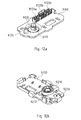
- FIG. 12a shows a further embodiment of a first mounting part 9100. This has on a mounting side designed as a pin 9110 centering means and contacting 9120a-c. The pin 9110 is as with respect to the FIGS. 1 to 9 described trained. Further, on the mounting side of the first mounting part 9100, a pin 9130 is provided.
- FIG. 12b shows a second mounting part 9200 according to another embodiment, which with the in FIG. 12a shown first assembly part 9100 can cooperate in a mounting system.
- the second mounting part 9200 On a mounting side, the second mounting part 9200 has a receiving means 9210 which, as with respect to FIGS. 1 to 9 is formed described. Further, an opening 9230 for receiving the pin 9130 of the first mounting part 9100 is provided on the mounting side.
- the second mounting part 9200 further comprises contacting means for coupling the contacting means 9120a-c of the first mounting part 9100 of FIG Fig. 12a on.
- FIG. 12c is the second mounting part 9200 of FIG. 12b shown in a top view on the mounting side.
- the pin 9130 and the opening 9230 ensures that the first 9100 and the second 9200 mounting part can not be mounted against each other twisted.
- a lateral projection 9117 is formed on the pin 9110, which corresponds to a lateral recess 9217 in the receiving means 9210. This also prevents mounting of the mounting parts in a twisted position.
- pin and receiving means may comprise in such an embodiment such means for torsion-proof mounting.
- the mounting system can be equipped with three-pole, five-pole and seven-pole connectors as contacting means, as in FIG. 13 shown.
- a three-pin plug 510 is sufficient.
- a five-pin connector 550 is used.
- a 5-pin 520, 530 plug is also used. So that these five-pin plug variants can not be mistakenly inserted incorrectly, a right 520, 530, 540 and a left 550 five-pin plug is provided on one side.
- a seven-pole variant of the contacting means as provided with reference numerals 560, 570, 580, allows both the operation of DALI and an emergency power function of the lamp.
- first or the second contacting means may be displaceable relative to the first or second centering means.
Landscapes
- Non-Portable Lighting Devices Or Systems Thereof (AREA)
- Fastening Of Light Sources Or Lamp Holders (AREA)
Applications Claiming Priority (1)
| Application Number | Priority Date | Filing Date | Title |
|---|---|---|---|
| DE201210102360 DE102012102360A1 (de) | 2012-03-20 | 2012-03-20 | Leuchtenmontagesystem |
Publications (3)
| Publication Number | Publication Date |
|---|---|
| EP2642613A2 true EP2642613A2 (fr) | 2013-09-25 |
| EP2642613A3 EP2642613A3 (fr) | 2014-11-12 |
| EP2642613B1 EP2642613B1 (fr) | 2019-06-12 |
Family
ID=47845761
Family Applications (1)
| Application Number | Title | Priority Date | Filing Date |
|---|---|---|---|
| EP13158018.5A Active EP2642613B1 (fr) | 2012-03-20 | 2013-03-06 | Système de montage de lampes |
Country Status (2)
| Country | Link |
|---|---|
| EP (1) | EP2642613B1 (fr) |
| DE (1) | DE102012102360A1 (fr) |
Cited By (6)
| Publication number | Priority date | Publication date | Assignee | Title |
|---|---|---|---|---|
| DE202014104416U1 (de) * | 2014-09-17 | 2015-12-18 | Zumtobel Lighting Gmbh | Leuchtenkupplung für Beleuchtungssystem |
| EP3282178A1 (fr) * | 2016-08-10 | 2018-02-14 | S-TEC electronics AG | Connecteur pour un corps de la lampe |
| EP3306185A1 (fr) * | 2016-10-10 | 2018-04-11 | Matthäus Wimmer | Luminaire |
| DE102017008622A1 (de) * | 2017-09-14 | 2019-03-14 | Helmut Lorenz | Beleuchtungsvorrichtung zur Anbringung an einem mit elektrischen Anschlussmitteln versehenen Bauwerksflächenabschnitt |
| IT201800002263A1 (it) * | 2018-01-31 | 2019-07-31 | Adriani E Rossi Edizioni S R L | Apparato di illuminazione |
| CN114270814A (zh) * | 2019-08-20 | 2022-04-01 | 达美尔电子有限及两合公司 | 用于悬挂地安装物体、尤其是监控相机的保持组件和方法 |
Citations (3)
| Publication number | Priority date | Publication date | Assignee | Title |
|---|---|---|---|---|
| DE102004039904A1 (de) | 2004-04-27 | 2005-12-01 | Andreas Dr. Rainer | Vorrichtung zum Befestigen einer elektrischen Installationseinheit an einer Decke oder Wand eines Gebäudes |
| DE202006006613U1 (de) | 2006-04-22 | 2006-07-06 | Gimpel, Matthias, Dipl.-Phys.-Ing. | Befestigungssystem für Lampen |
| DE102007001533A1 (de) | 2007-01-10 | 2008-07-17 | Osram Opto Semiconductors Gmbh | Leuchtdiodensystem |
Family Cites Families (6)
| Publication number | Priority date | Publication date | Assignee | Title |
|---|---|---|---|---|
| DE644823C (de) * | 1937-05-13 | Georg Griesinger | Deckensteckvorrichtung | |
| US6074235A (en) * | 1998-04-07 | 2000-06-13 | The Whitaker Corporation | Alignment post having an improved locking feature |
| US6962498B2 (en) * | 2001-12-12 | 2005-11-08 | Ran Kohen | Revolvable plug and socket |
| DE20117303U1 (de) * | 2001-10-25 | 2003-02-27 | Erni Elektroapparate Gmbh, 73099 Adelberg | Führungssystem für Kontaktstecker |
| US7297022B2 (en) * | 2005-06-02 | 2007-11-20 | Hunter Fan Company | Ceiling fan hanging system |
| US8231403B2 (en) * | 2010-08-31 | 2012-07-31 | Smith Benjamin J | Quick mounting device |
-
2012
- 2012-03-20 DE DE201210102360 patent/DE102012102360A1/de not_active Withdrawn
-
2013
- 2013-03-06 EP EP13158018.5A patent/EP2642613B1/fr active Active
Patent Citations (3)
| Publication number | Priority date | Publication date | Assignee | Title |
|---|---|---|---|---|
| DE102004039904A1 (de) | 2004-04-27 | 2005-12-01 | Andreas Dr. Rainer | Vorrichtung zum Befestigen einer elektrischen Installationseinheit an einer Decke oder Wand eines Gebäudes |
| DE202006006613U1 (de) | 2006-04-22 | 2006-07-06 | Gimpel, Matthias, Dipl.-Phys.-Ing. | Befestigungssystem für Lampen |
| DE102007001533A1 (de) | 2007-01-10 | 2008-07-17 | Osram Opto Semiconductors Gmbh | Leuchtdiodensystem |
Cited By (7)
| Publication number | Priority date | Publication date | Assignee | Title |
|---|---|---|---|---|
| DE202014104416U1 (de) * | 2014-09-17 | 2015-12-18 | Zumtobel Lighting Gmbh | Leuchtenkupplung für Beleuchtungssystem |
| EP3282178A1 (fr) * | 2016-08-10 | 2018-02-14 | S-TEC electronics AG | Connecteur pour un corps de la lampe |
| EP3306185A1 (fr) * | 2016-10-10 | 2018-04-11 | Matthäus Wimmer | Luminaire |
| WO2018068906A1 (fr) | 2016-10-10 | 2018-04-19 | Wimmer Matthaeus | Luminaire |
| DE102017008622A1 (de) * | 2017-09-14 | 2019-03-14 | Helmut Lorenz | Beleuchtungsvorrichtung zur Anbringung an einem mit elektrischen Anschlussmitteln versehenen Bauwerksflächenabschnitt |
| IT201800002263A1 (it) * | 2018-01-31 | 2019-07-31 | Adriani E Rossi Edizioni S R L | Apparato di illuminazione |
| CN114270814A (zh) * | 2019-08-20 | 2022-04-01 | 达美尔电子有限及两合公司 | 用于悬挂地安装物体、尤其是监控相机的保持组件和方法 |
Also Published As
| Publication number | Publication date |
|---|---|
| EP2642613B1 (fr) | 2019-06-12 |
| DE102012102360A1 (de) | 2013-09-26 |
| EP2642613A3 (fr) | 2014-11-12 |
Similar Documents
| Publication | Publication Date | Title |
|---|---|---|
| EP2642613B1 (fr) | Système de montage de lampes | |
| DE102014213468B4 (de) | Leuchte für eine Rasterdecke, Verfahren zum Demontieren einer Leuchte, sowie Demontagewerkzeug | |
| DE202008015309U1 (de) | Montagesystem für elektrische und/oder mechanische Komponenten | |
| EP3242072B1 (fr) | Système d'éclairage | |
| EP2086077A2 (fr) | Système de montage pour composants électriques et/ou mécaniques | |
| DE202015100360U1 (de) | Kabelhalter und Kabelhaltersystem | |
| EP2650594B1 (fr) | Eclairage doté d'une lampe | |
| DE102007005737A1 (de) | Kopfstützensystem für einen Fahrzeugsitz | |
| AT14622U1 (de) | Leuchte bzw. Beleuchtungsanordnung mit länglichem Trägerelement und lösbar befestigbarem Leuchtmodul | |
| EP3608588B1 (fr) | Ressort de maintien pour luminaire | |
| DE102011083993B4 (de) | Lichtband | |
| AT14214U1 (de) | Leuchte mit auswechselbarem Leuchtmittel-Modul | |
| EP2827052B1 (fr) | Éclairage | |
| EP3015359B1 (fr) | Dispositif de fixation et mise en contact électrique d'un carénage d'un aéronef sur une structure porteuse | |
| DE102011078738A1 (de) | Montagesystem | |
| DE102021212616B4 (de) | Leuchte mit Tragprofil, Stromführungsschiene und Stecker | |
| DE102014013658B4 (de) | Montagesystem, Befestigungseinrichtung und Verfahren zur Befestigung einer Leuchte und Leuchte mit einer Befestigungseinrichtung | |
| DE202018106703U1 (de) | Wand- oder Deckenleuchte | |
| EP2757546B1 (fr) | Tableau indicateur, notamment pour une installation d'éclairage de secours | |
| DE102004018381B4 (de) | Deckenleuchte | |
| EP3246623B1 (fr) | Éclairage comprenant une carte de circuit imprimé del sur un support de tôle | |
| EP1351559B1 (fr) | Système de fixation des composants électriques et/ou mécaniques d'un luminaire | |
| DE102023119082A1 (de) | Lichtband mit Kratzfederkupplung | |
| DE102004040029B4 (de) | Befestigungssystem für ein elektrisches Gerät zur Installation in Flugzeugkabinen | |
| DE102023122124A1 (de) | System zur Befestigung mindestens eines elektrischen Funktionselementes |
Legal Events
| Date | Code | Title | Description |
|---|---|---|---|
| PUAI | Public reference made under article 153(3) epc to a published international application that has entered the european phase |
Free format text: ORIGINAL CODE: 0009012 |
|
| AK | Designated contracting states |
Kind code of ref document: A2 Designated state(s): AL AT BE BG CH CY CZ DE DK EE ES FI FR GB GR HR HU IE IS IT LI LT LU LV MC MK MT NL NO PL PT RO RS SE SI SK SM TR |
|
| AX | Request for extension of the european patent |
Extension state: BA ME |
|
| PUAL | Search report despatched |
Free format text: ORIGINAL CODE: 0009013 |
|
| AK | Designated contracting states |
Kind code of ref document: A3 Designated state(s): AL AT BE BG CH CY CZ DE DK EE ES FI FR GB GR HR HU IE IS IT LI LT LU LV MC MK MT NL NO PL PT RO RS SE SI SK SM TR |
|
| AX | Request for extension of the european patent |
Extension state: BA ME |
|
| RIC1 | Information provided on ipc code assigned before grant |
Ipc: H01R 13/631 20060101AFI20141008BHEP Ipc: F21V 23/06 20060101ALI20141008BHEP Ipc: F21V 21/03 20060101ALI20141008BHEP Ipc: H01R 13/627 20060101ALI20141008BHEP |
|
| 17P | Request for examination filed |
Effective date: 20150402 |
|
| RBV | Designated contracting states (corrected) |
Designated state(s): AL AT BE BG CH CY CZ DE DK EE ES FI FR GB GR HR HU IE IS IT LI LT LU LV MC MK MT NL NO PL PT RO RS SE SI SK SM TR |
|
| 17Q | First examination report despatched |
Effective date: 20151130 |
|
| STAA | Information on the status of an ep patent application or granted ep patent |
Free format text: STATUS: EXAMINATION IS IN PROGRESS |
|
| GRAP | Despatch of communication of intention to grant a patent |
Free format text: ORIGINAL CODE: EPIDOSNIGR1 |
|
| STAA | Information on the status of an ep patent application or granted ep patent |
Free format text: STATUS: GRANT OF PATENT IS INTENDED |
|
| INTG | Intention to grant announced |
Effective date: 20180926 |
|
| GRAJ | Information related to disapproval of communication of intention to grant by the applicant or resumption of examination proceedings by the epo deleted |
Free format text: ORIGINAL CODE: EPIDOSDIGR1 |
|
| STAA | Information on the status of an ep patent application or granted ep patent |
Free format text: STATUS: EXAMINATION IS IN PROGRESS |
|
| GRAP | Despatch of communication of intention to grant a patent |
Free format text: ORIGINAL CODE: EPIDOSNIGR1 |
|
| STAA | Information on the status of an ep patent application or granted ep patent |
Free format text: STATUS: GRANT OF PATENT IS INTENDED |
|
| INTC | Intention to grant announced (deleted) | ||
| INTG | Intention to grant announced |
Effective date: 20190102 |
|
| GRAS | Grant fee paid |
Free format text: ORIGINAL CODE: EPIDOSNIGR3 |
|
| GRAA | (expected) grant |
Free format text: ORIGINAL CODE: 0009210 |
|
| STAA | Information on the status of an ep patent application or granted ep patent |
Free format text: STATUS: THE PATENT HAS BEEN GRANTED |
|
| AK | Designated contracting states |
Kind code of ref document: B1 Designated state(s): AL AT BE BG CH CY CZ DE DK EE ES FI FR GB GR HR HU IE IS IT LI LT LU LV MC MK MT NL NO PL PT RO RS SE SI SK SM TR |
|
| REG | Reference to a national code |
Ref country code: GB Ref legal event code: FG4D Free format text: NOT ENGLISH |
|
| REG | Reference to a national code |
Ref country code: CH Ref legal event code: EP |
|
| REG | Reference to a national code |
Ref country code: AT Ref legal event code: REF Ref document number: 1143831 Country of ref document: AT Kind code of ref document: T Effective date: 20190615 |
|
| REG | Reference to a national code |
Ref country code: DE Ref legal event code: R096 Ref document number: 502013012966 Country of ref document: DE |
|
| REG | Reference to a national code |
Ref country code: IE Ref legal event code: FG4D Free format text: LANGUAGE OF EP DOCUMENT: GERMAN |
|
| REG | Reference to a national code |
Ref country code: NL Ref legal event code: MP Effective date: 20190612 |
|
| REG | Reference to a national code |
Ref country code: LT Ref legal event code: MG4D |
|
| PG25 | Lapsed in a contracting state [announced via postgrant information from national office to epo] |
Ref country code: FI Free format text: LAPSE BECAUSE OF FAILURE TO SUBMIT A TRANSLATION OF THE DESCRIPTION OR TO PAY THE FEE WITHIN THE PRESCRIBED TIME-LIMIT Effective date: 20190612 Ref country code: LT Free format text: LAPSE BECAUSE OF FAILURE TO SUBMIT A TRANSLATION OF THE DESCRIPTION OR TO PAY THE FEE WITHIN THE PRESCRIBED TIME-LIMIT Effective date: 20190612 Ref country code: HR Free format text: LAPSE BECAUSE OF FAILURE TO SUBMIT A TRANSLATION OF THE DESCRIPTION OR TO PAY THE FEE WITHIN THE PRESCRIBED TIME-LIMIT Effective date: 20190612 Ref country code: SE Free format text: LAPSE BECAUSE OF FAILURE TO SUBMIT A TRANSLATION OF THE DESCRIPTION OR TO PAY THE FEE WITHIN THE PRESCRIBED TIME-LIMIT Effective date: 20190612 Ref country code: NO Free format text: LAPSE BECAUSE OF FAILURE TO SUBMIT A TRANSLATION OF THE DESCRIPTION OR TO PAY THE FEE WITHIN THE PRESCRIBED TIME-LIMIT Effective date: 20190912 Ref country code: AL Free format text: LAPSE BECAUSE OF FAILURE TO SUBMIT A TRANSLATION OF THE DESCRIPTION OR TO PAY THE FEE WITHIN THE PRESCRIBED TIME-LIMIT Effective date: 20190612 Ref country code: ES Free format text: LAPSE BECAUSE OF FAILURE TO SUBMIT A TRANSLATION OF THE DESCRIPTION OR TO PAY THE FEE WITHIN THE PRESCRIBED TIME-LIMIT Effective date: 20190612 |
|
| PG25 | Lapsed in a contracting state [announced via postgrant information from national office to epo] |
Ref country code: BG Free format text: LAPSE BECAUSE OF FAILURE TO SUBMIT A TRANSLATION OF THE DESCRIPTION OR TO PAY THE FEE WITHIN THE PRESCRIBED TIME-LIMIT Effective date: 20190912 Ref country code: RS Free format text: LAPSE BECAUSE OF FAILURE TO SUBMIT A TRANSLATION OF THE DESCRIPTION OR TO PAY THE FEE WITHIN THE PRESCRIBED TIME-LIMIT Effective date: 20190612 Ref country code: LV Free format text: LAPSE BECAUSE OF FAILURE TO SUBMIT A TRANSLATION OF THE DESCRIPTION OR TO PAY THE FEE WITHIN THE PRESCRIBED TIME-LIMIT Effective date: 20190612 Ref country code: GR Free format text: LAPSE BECAUSE OF FAILURE TO SUBMIT A TRANSLATION OF THE DESCRIPTION OR TO PAY THE FEE WITHIN THE PRESCRIBED TIME-LIMIT Effective date: 20190913 |
|
| PG25 | Lapsed in a contracting state [announced via postgrant information from national office to epo] |
Ref country code: SK Free format text: LAPSE BECAUSE OF FAILURE TO SUBMIT A TRANSLATION OF THE DESCRIPTION OR TO PAY THE FEE WITHIN THE PRESCRIBED TIME-LIMIT Effective date: 20190612 Ref country code: RO Free format text: LAPSE BECAUSE OF FAILURE TO SUBMIT A TRANSLATION OF THE DESCRIPTION OR TO PAY THE FEE WITHIN THE PRESCRIBED TIME-LIMIT Effective date: 20190612 Ref country code: EE Free format text: LAPSE BECAUSE OF FAILURE TO SUBMIT A TRANSLATION OF THE DESCRIPTION OR TO PAY THE FEE WITHIN THE PRESCRIBED TIME-LIMIT Effective date: 20190612 Ref country code: PT Free format text: LAPSE BECAUSE OF FAILURE TO SUBMIT A TRANSLATION OF THE DESCRIPTION OR TO PAY THE FEE WITHIN THE PRESCRIBED TIME-LIMIT Effective date: 20191014 Ref country code: NL Free format text: LAPSE BECAUSE OF FAILURE TO SUBMIT A TRANSLATION OF THE DESCRIPTION OR TO PAY THE FEE WITHIN THE PRESCRIBED TIME-LIMIT Effective date: 20190612 Ref country code: CZ Free format text: LAPSE BECAUSE OF FAILURE TO SUBMIT A TRANSLATION OF THE DESCRIPTION OR TO PAY THE FEE WITHIN THE PRESCRIBED TIME-LIMIT Effective date: 20190612 |
|
| PG25 | Lapsed in a contracting state [announced via postgrant information from national office to epo] |
Ref country code: SM Free format text: LAPSE BECAUSE OF FAILURE TO SUBMIT A TRANSLATION OF THE DESCRIPTION OR TO PAY THE FEE WITHIN THE PRESCRIBED TIME-LIMIT Effective date: 20190612 Ref country code: IT Free format text: LAPSE BECAUSE OF FAILURE TO SUBMIT A TRANSLATION OF THE DESCRIPTION OR TO PAY THE FEE WITHIN THE PRESCRIBED TIME-LIMIT Effective date: 20190612 Ref country code: IS Free format text: LAPSE BECAUSE OF FAILURE TO SUBMIT A TRANSLATION OF THE DESCRIPTION OR TO PAY THE FEE WITHIN THE PRESCRIBED TIME-LIMIT Effective date: 20191012 |
|
| REG | Reference to a national code |
Ref country code: DE Ref legal event code: R097 Ref document number: 502013012966 Country of ref document: DE |
|
| RAP2 | Party data changed (patent owner data changed or rights of a patent transferred) |
Owner name: SITECO GMBH |
|
| PG25 | Lapsed in a contracting state [announced via postgrant information from national office to epo] |
Ref country code: TR Free format text: LAPSE BECAUSE OF FAILURE TO SUBMIT A TRANSLATION OF THE DESCRIPTION OR TO PAY THE FEE WITHIN THE PRESCRIBED TIME-LIMIT Effective date: 20190612 |
|
| PLBE | No opposition filed within time limit |
Free format text: ORIGINAL CODE: 0009261 |
|
| STAA | Information on the status of an ep patent application or granted ep patent |
Free format text: STATUS: NO OPPOSITION FILED WITHIN TIME LIMIT |
|
| PG25 | Lapsed in a contracting state [announced via postgrant information from national office to epo] |
Ref country code: PL Free format text: LAPSE BECAUSE OF FAILURE TO SUBMIT A TRANSLATION OF THE DESCRIPTION OR TO PAY THE FEE WITHIN THE PRESCRIBED TIME-LIMIT Effective date: 20190612 Ref country code: DK Free format text: LAPSE BECAUSE OF FAILURE TO SUBMIT A TRANSLATION OF THE DESCRIPTION OR TO PAY THE FEE WITHIN THE PRESCRIBED TIME-LIMIT Effective date: 20190612 |
|
| 26N | No opposition filed |
Effective date: 20200313 |
|
| PG25 | Lapsed in a contracting state [announced via postgrant information from national office to epo] |
Ref country code: SI Free format text: LAPSE BECAUSE OF FAILURE TO SUBMIT A TRANSLATION OF THE DESCRIPTION OR TO PAY THE FEE WITHIN THE PRESCRIBED TIME-LIMIT Effective date: 20190612 Ref country code: IS Free format text: LAPSE BECAUSE OF FAILURE TO SUBMIT A TRANSLATION OF THE DESCRIPTION OR TO PAY THE FEE WITHIN THE PRESCRIBED TIME-LIMIT Effective date: 20200224 |
|
| PG2D | Information on lapse in contracting state deleted |
Ref country code: IS |
|
| PG25 | Lapsed in a contracting state [announced via postgrant information from national office to epo] |
Ref country code: MC Free format text: LAPSE BECAUSE OF FAILURE TO SUBMIT A TRANSLATION OF THE DESCRIPTION OR TO PAY THE FEE WITHIN THE PRESCRIBED TIME-LIMIT Effective date: 20190612 |
|
| REG | Reference to a national code |
Ref country code: CH Ref legal event code: PL |
|
| REG | Reference to a national code |
Ref country code: AT Ref legal event code: PC Ref document number: 1143831 Country of ref document: AT Kind code of ref document: T Owner name: SITECO GMBH, DE Effective date: 20201028 |
|
| REG | Reference to a national code |
Ref country code: BE Ref legal event code: MM Effective date: 20200331 |
|
| PG25 | Lapsed in a contracting state [announced via postgrant information from national office to epo] |
Ref country code: LU Free format text: LAPSE BECAUSE OF NON-PAYMENT OF DUE FEES Effective date: 20200306 |
|
| PG25 | Lapsed in a contracting state [announced via postgrant information from national office to epo] |
Ref country code: IE Free format text: LAPSE BECAUSE OF NON-PAYMENT OF DUE FEES Effective date: 20200306 Ref country code: LI Free format text: LAPSE BECAUSE OF NON-PAYMENT OF DUE FEES Effective date: 20200331 Ref country code: FR Free format text: LAPSE BECAUSE OF NON-PAYMENT OF DUE FEES Effective date: 20200331 Ref country code: CH Free format text: LAPSE BECAUSE OF NON-PAYMENT OF DUE FEES Effective date: 20200331 |
|
| PG25 | Lapsed in a contracting state [announced via postgrant information from national office to epo] |
Ref country code: BE Free format text: LAPSE BECAUSE OF NON-PAYMENT OF DUE FEES Effective date: 20200331 |
|
| GBPC | Gb: european patent ceased through non-payment of renewal fee |
Effective date: 20200306 |
|
| PG25 | Lapsed in a contracting state [announced via postgrant information from national office to epo] |
Ref country code: GB Free format text: LAPSE BECAUSE OF NON-PAYMENT OF DUE FEES Effective date: 20200306 |
|
| REG | Reference to a national code |
Ref country code: DE Ref legal event code: R082 Ref document number: 502013012966 Country of ref document: DE Representative=s name: BOEHMERT & BOEHMERT ANWALTSPARTNERSCHAFT MBB -, DE Ref country code: DE Ref legal event code: R081 Ref document number: 502013012966 Country of ref document: DE Owner name: SITECO GMBH, DE Free format text: FORMER OWNER: SITECO BELEUCHTUNGSTECHNIK GMBH, 83301 TRAUNREUT, DE |
|
| PG25 | Lapsed in a contracting state [announced via postgrant information from national office to epo] |
Ref country code: MT Free format text: LAPSE BECAUSE OF FAILURE TO SUBMIT A TRANSLATION OF THE DESCRIPTION OR TO PAY THE FEE WITHIN THE PRESCRIBED TIME-LIMIT Effective date: 20190612 Ref country code: CY Free format text: LAPSE BECAUSE OF FAILURE TO SUBMIT A TRANSLATION OF THE DESCRIPTION OR TO PAY THE FEE WITHIN THE PRESCRIBED TIME-LIMIT Effective date: 20190612 |
|
| PG25 | Lapsed in a contracting state [announced via postgrant information from national office to epo] |
Ref country code: MK Free format text: LAPSE BECAUSE OF FAILURE TO SUBMIT A TRANSLATION OF THE DESCRIPTION OR TO PAY THE FEE WITHIN THE PRESCRIBED TIME-LIMIT Effective date: 20190612 |
|
| PGFP | Annual fee paid to national office [announced via postgrant information from national office to epo] |
Ref country code: DE Payment date: 20260320 Year of fee payment: 14 |
|
| PGFP | Annual fee paid to national office [announced via postgrant information from national office to epo] |
Ref country code: AT Payment date: 20260319 Year of fee payment: 14 |