EP2642647A1 - Stator und Verfahren zur Herstellung eines Stators - Google Patents
Stator und Verfahren zur Herstellung eines Stators Download PDFInfo
- Publication number
- EP2642647A1 EP2642647A1 EP12160697.4A EP12160697A EP2642647A1 EP 2642647 A1 EP2642647 A1 EP 2642647A1 EP 12160697 A EP12160697 A EP 12160697A EP 2642647 A1 EP2642647 A1 EP 2642647A1
- Authority
- EP
- European Patent Office
- Prior art keywords
- casing
- stator
- key bar
- sheets
- key
- Prior art date
- Legal status (The legal status is an assumption and is not a legal conclusion. Google has not performed a legal analysis and makes no representation as to the accuracy of the status listed.)
- Withdrawn
Links
Images

Classifications
-
- H—ELECTRICITY
- H02—GENERATION; CONVERSION OR DISTRIBUTION OF ELECTRIC POWER
- H02K—DYNAMO-ELECTRIC MACHINES
- H02K15/00—Processes or apparatus specially adapted for manufacturing, assembling, maintaining or repairing of dynamo-electric machines
- H02K15/02—Processes or apparatus specially adapted for manufacturing, assembling, maintaining or repairing of dynamo-electric machines of stator or rotor bodies
- H02K15/028—Fastening stator or rotor bodies to casings, supports, shafts or hubs
-
- H—ELECTRICITY
- H02—GENERATION; CONVERSION OR DISTRIBUTION OF ELECTRIC POWER
- H02K—DYNAMO-ELECTRIC MACHINES
- H02K1/00—Details of the magnetic circuit
- H02K1/06—Details of the magnetic circuit characterised by the shape, form or construction
- H02K1/12—Stationary parts of the magnetic circuit
- H02K1/18—Means for mounting or fastening magnetic stationary parts on to, or to, the stator structures
- H02K1/185—Means for mounting or fastening magnetic stationary parts on to, or to, the stator structures to outer stators
Definitions
- the present disclosure relates to a stator and a method for manufacturing a stator.
- the stator is a part of an electric machine such as a synchronous or asynchronous electric generator or a synchronous or asynchronous electric motor. Other kinds of electric machines are anyhow possible.
- a casing In order to manufacture a stator of a large electric machine, usually a casing is positioned in the vertical configuration with a press plate at its bottom. Then key bars are welded to the casing and metal sheets are inserted one by one into the casing. Finally a second press plate is provided at the top of the metal sheets.
- the key bars are used to align the metal sheets one another, for this reason the positioning of the key bars within the casing must be precise.
- the key bars must have a good electric contact with the metal sheets to prevent eddy currents and hot spots.
- the welding time can be very long.
- welding can cause distortions of the interested parts, such that once a key bar is welded to the casing its positioning and/or features (for example its straightness or dimensional tolerances) have to be checked. In case positioning and/or features can not be accepted, the key bar must be removed, grinded and re-welded.
- An aspect of the disclosure includes providing a stator and a method by which manufacturing of the stator is easy and quick, in particular when compared to the known methods.
- stator of an electric machine such as an electric generator or an electric motor is described first.
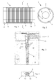
- the stator 1 comprises a casing 2 for example having a cylindrical configuration; the casing 2 has a first press plate 3 at one end.
- a plurality of sheets 4 that define the stator core are provided; the sheets 4 are usually metal sheets and are connected to one or more key bars 6.
- a second press plate 7 is provided at another end of the casing 2.
- the key bars 6 are connected to the casing 2 by adjustable elements 9.
- wedges 10 are provided between the key bars 6 and the sheets 4; this improves electric and mechanical connection between the key bars 6 and the sheets 4.
- the key bars 6 are connected to the casing 2; for example the casing 2 has key bar carriers 12 and each key bar 6 is connected to a key bar carrier 12.
- the key bar carriers 12 are bars connected (for example welded) to the rest of the casing 2, such that they define a solid component.
- the press plates 3, 7 are advantageously connected to the key bar carriers 12.
- the adjustable elements 9 can be any, for example they can include screws and/or pins and/or bolts.
- no tension bars to connect the press plates 3, 7 together separate from the key bar carriers 12 are provided. This proved to be advantageous because when separate tension bars to connect the press plates together are provided, they are housed in holes drilled in the sheets 4, such that the electrically used surface of the metal sheets (i.e. the cross section of the stator core) is reduced. For this reason, preferably the stator is a stator of a four pole electric machine.
- spacers 15, 16 can be provided between each press plate 3, 7 and the sheets 4.
- the method for manufacturing the stator 1 comprises the following steps:
- the key bars 6 are connected to the casing 2 by the adjustable elements 9 such as screws and/or pins and/or others, and the configuration of the key bars 6 is adjusted after the key bars 6 are connected to the casing 2 and before the sheets 4 are provided into the casing 2 ( figure 9 ).
- Arrows F indicate possible adjustments that can be carried out.
- the total assembling time can be sensibly reduced when compared to the traditional methods.
- the removable elements 9 allow an easier connection, they allow a better electric contact to be achieved between the key bars 6 and the metal sheets 4 (or key bar carrier 12); anyhow, when the electrical connection (i.e. resistance) is not acceptable, removal and re-connection of the key bars 6 is easy and fast.
- wedges 10 can be provided between the key bars 6 and the metal sheets 4 to improve mechanical and electrical connection (i.e. improve stiffness and reduce electric resistance) between the key bars 6 and the metal sheets 4.
- press plates 3, 7 are then connected to the casing 2 (in particular to the key bar carriers 12 that are part of the casing 2) and spacers 15, 16 are preferably provided between each press plate 3, 7 and the sheets 4. This last step is anyhow not mandatory.
Landscapes
- Engineering & Computer Science (AREA)
- Power Engineering (AREA)
- Manufacturing & Machinery (AREA)
- Manufacture Of Motors, Generators (AREA)
- Iron Core Of Rotating Electric Machines (AREA)
Priority Applications (1)
| Application Number | Priority Date | Filing Date | Title |
|---|---|---|---|
| EP12160697.4A EP2642647A1 (de) | 2012-03-22 | 2012-03-22 | Stator und Verfahren zur Herstellung eines Stators |
Applications Claiming Priority (1)
| Application Number | Priority Date | Filing Date | Title |
|---|---|---|---|
| EP12160697.4A EP2642647A1 (de) | 2012-03-22 | 2012-03-22 | Stator und Verfahren zur Herstellung eines Stators |
Publications (1)
| Publication Number | Publication Date |
|---|---|
| EP2642647A1 true EP2642647A1 (de) | 2013-09-25 |
Family
ID=45932163
Family Applications (1)
| Application Number | Title | Priority Date | Filing Date |
|---|---|---|---|
| EP12160697.4A Withdrawn EP2642647A1 (de) | 2012-03-22 | 2012-03-22 | Stator und Verfahren zur Herstellung eines Stators |
Country Status (1)
| Country | Link |
|---|---|
| EP (1) | EP2642647A1 (de) |
Citations (5)
| Publication number | Priority date | Publication date | Assignee | Title |
|---|---|---|---|---|
| DE1638190A1 (de) * | 1966-05-20 | 1970-06-11 | Elin Union Ag | Einrichtung zum Aufbau des Staenderblechpaketes im Gehaeuse elektrischer Maschinen |
| DE1613224A1 (de) * | 1967-04-21 | 1971-01-21 | Licentia Gmbh | Radial federnde Aufhaengung von Staenderblechpaketen elektrischer Maschinen |
| JPS5937836U (ja) * | 1982-09-02 | 1984-03-09 | 富士電機株式会社 | 回転電機の固定子鉄心支持構造 |
| US4634909A (en) * | 1984-08-08 | 1987-01-06 | Bbc Brown, Boveri & Company Limited | Electric machine |
| US4891540A (en) * | 1988-11-01 | 1990-01-02 | Westinghouse Electric Corp. | Generator core support system |
-
2012
- 2012-03-22 EP EP12160697.4A patent/EP2642647A1/de not_active Withdrawn
Patent Citations (5)
| Publication number | Priority date | Publication date | Assignee | Title |
|---|---|---|---|---|
| DE1638190A1 (de) * | 1966-05-20 | 1970-06-11 | Elin Union Ag | Einrichtung zum Aufbau des Staenderblechpaketes im Gehaeuse elektrischer Maschinen |
| DE1613224A1 (de) * | 1967-04-21 | 1971-01-21 | Licentia Gmbh | Radial federnde Aufhaengung von Staenderblechpaketen elektrischer Maschinen |
| JPS5937836U (ja) * | 1982-09-02 | 1984-03-09 | 富士電機株式会社 | 回転電機の固定子鉄心支持構造 |
| US4634909A (en) * | 1984-08-08 | 1987-01-06 | Bbc Brown, Boveri & Company Limited | Electric machine |
| US4891540A (en) * | 1988-11-01 | 1990-01-02 | Westinghouse Electric Corp. | Generator core support system |
Similar Documents
| Publication | Publication Date | Title |
|---|---|---|
| EP1592107B1 (de) | Statorkernbaugruppe | |
| US7397163B2 (en) | Power generator stator assembly, a stator core module assembly, and a process for assembling a stator core module assembly within a stator frame | |
| EP1811634B1 (de) | Verbindungsanordnung für die Statorwicklung einer Turbomaschine mit 2 oder mehr parallelen Kreisen | |
| EP2847854B1 (de) | Stützanordnung zur wartung eines statorgehäuses mit federbaugruppen zur unterstützung eines statorkerns | |
| KR101691275B1 (ko) | 스테이터를 지지하기 위해서 스프링 조립체를 포함하는 스테이터 프레임을 서비스하는 방법 | |
| DE112011105658T5 (de) | Stator einer drehenden elektrischen Maschine | |
| EP1915813A1 (de) | Käfigläufer einer asynchronmaschine | |
| US9825511B2 (en) | Method for repairing a stator | |
| EP2227851B1 (de) | Generatorstatoranordnung | |
| EP2602799A1 (de) | Spulenhalterung und Öltransformator | |
| EP2642647A1 (de) | Stator und Verfahren zur Herstellung eines Stators | |
| EP2642646B1 (de) | Verfahren zur Herstellung eines Stators | |
| DE102014209582A1 (de) | Elektrische Maschine | |
| CN108141084B (zh) | 具有用于绕组接线的电路板组件的电动机器和制造方法 | |
| EP2498379A1 (de) | Verfahren zur gegenseitigen Verbindung von Leiterenden zur Spulenbestimmung einer elektrischen Maschine | |
| KR20160096097A (ko) | 전기 기계용 권선 | |
| CN110085394B (zh) | 一种双开口磁路工字型铁心柱夹紧固定装置及其使用方法 | |
| EP2673790B1 (de) | Transformator aus amorphem metall | |
| CN207184299U (zh) | 一种4mw同轴互馈式同步电动机 | |
| CN107404206B (zh) | 一种4mw同轴互馈式同步电动机 | |
| US9653972B2 (en) | Method and device for manufacturing a laminated stator core | |
| CN110798032A (zh) | 一种发电机转子线圈积木式装配工装及使用方法 | |
| CN118249538A (zh) | 一种改善大型发电机定子铁芯齿部受力的辅助支撑装置及使用方法 | |
| CN209125714U (zh) | 螺母组件锁紧工装 | |
| EP2337187B1 (de) | Pol-zu-Pol-Verbindungsanordnung für einen Generator |
Legal Events
| Date | Code | Title | Description |
|---|---|---|---|
| PUAI | Public reference made under article 153(3) epc to a published international application that has entered the european phase |
Free format text: ORIGINAL CODE: 0009012 |
|
| AK | Designated contracting states |
Kind code of ref document: A1 Designated state(s): AL AT BE BG CH CY CZ DE DK EE ES FI FR GB GR HR HU IE IS IT LI LT LU LV MC MK MT NL NO PL PT RO RS SE SI SK SM TR |
|
| AX | Request for extension of the european patent |
Extension state: BA ME |
|
| STAA | Information on the status of an ep patent application or granted ep patent |
Free format text: STATUS: THE APPLICATION IS DEEMED TO BE WITHDRAWN |
|
| 18D | Application deemed to be withdrawn |
Effective date: 20140326 |