EP2642889B1 - SCHUBLADENSEITENWAND MIT EINER INNENWAND UND EINER AUßENWAND - Google Patents
SCHUBLADENSEITENWAND MIT EINER INNENWAND UND EINER AUßENWAND Download PDFInfo
- Publication number
- EP2642889B1 EP2642889B1 EP11782359.1A EP11782359A EP2642889B1 EP 2642889 B1 EP2642889 B1 EP 2642889B1 EP 11782359 A EP11782359 A EP 11782359A EP 2642889 B1 EP2642889 B1 EP 2642889B1
- Authority
- EP
- European Patent Office
- Prior art keywords
- wall
- side wall
- drawer side
- drawer
- latching
- Prior art date
- Legal status (The legal status is an assumption and is not a legal conclusion. Google has not performed a legal analysis and makes no representation as to the accuracy of the status listed.)
- Active
Links
Images




Classifications
-
- A—HUMAN NECESSITIES
- A47—FURNITURE; DOMESTIC ARTICLES OR APPLIANCES; COFFEE MILLS; SPICE MILLS; SUCTION CLEANERS IN GENERAL
- A47B—TABLES; DESKS; OFFICE FURNITURE; CABINETS; DRAWERS; GENERAL DETAILS OF FURNITURE
- A47B88/00—Drawers for tables, cabinets or like furniture; Guides for drawers
- A47B88/90—Constructional details of drawers
- A47B88/941—Drawers being constructed from two or more parts
-
- A—HUMAN NECESSITIES
- A47—FURNITURE; DOMESTIC ARTICLES OR APPLIANCES; COFFEE MILLS; SPICE MILLS; SUCTION CLEANERS IN GENERAL
- A47B—TABLES; DESKS; OFFICE FURNITURE; CABINETS; DRAWERS; GENERAL DETAILS OF FURNITURE
- A47B2210/00—General construction of drawers, guides and guide devices
- A47B2210/02—Drawers with hollow lateral walls in two parts
Definitions
- the invention relates to a drawer side wall having an inner wall and an outer wall, wherein the drawer side wall is to be connected to a drawer rail system, which lies at least largely within the inner wall, wherein the inner wall and the outer wall are connectable to each other via a mechanical latching connection, wherein the inner wall and the outer wall in the mounting position below the latching connection each have end sections.
- Multi-part drawer side walls or drawer frames are already known in the art. They typically consist of an inner wall and an outer wall which is to be connected to the inner wall. That's how it shows DE 41 23 213 A1 a side frame of a drawer consisting of two profile elements. An upper edge of the first profile element is bent outwards and pulled down, this retracted edge forms a designed as downwardly open groove retaining profile for the upper edge of the second profile element. An arranged on the first profile element boundary web for spacing the profile elements cooperates with a snap profile of the second profile element to connect the two profile elements. Also the EP 1 614 369 A1 shows a double-walled drawer frame, which comprises two wall parts.
- the two wall parts can be connected by a mechanical latching connection, wherein the latching connection is designed such that the two wall parts can be separated again in a simple and rapid manner.
- the end portions of the two wall parts are spaced apart below the latching connection.
- This is disadvantageous in that thereby also an unintentional loosening of the latching connection can easily be done, for example, by hooking on the end portion of the outer wall portion and thus detaches the outer wall portion of the inner wall portion.
- the DE 202 03 551 U1 also shows a double-walled drawer frame, wherein the two wall parts can be connected in the upper end regions by a holding part and in the lower end regions by a tongue and groove connection. Again, the end portions of the wall parts below the tongue and groove connection are spaced apart, so you can easily inadvertently hook on the end portion of the outer wall portion and solve the outer wall portion of the inner wall portion.
- the invention has therefore set itself the task of specifying a comparison with the prior art improved drawer side wall.
- an unintentional release of the latching connection and thus inadvertent release of the outer wall of the inner wall should be prevented.
- the end portion of the inner wall and the end portion of the outer wall at least partially abut each other, wherein the end portion of the outer wall projects beyond the end portion of the inner wall, and that the inner wall aul utilizata a latching receptacle, in which a latching part of the outer wall can be latched , wherein the locking part is pressed in a lifting of the downwardly projecting end portion of the outer wall from the end portion of the inner wall in the locking receptacle of the inner wall and thus prevents release of the latching connection.
- the latching connection is formed in that the inner wall has a latching receptacle into which a latching part of the outer wall can be latched.
- Both latching receptacle and latching part can each have a profiled leg which extends over part of the length of the drawer side wall.
- the profiling can in each case - in cross-section - be formed substantially S-shaped or Z-shaped. Such profilings allow in particular a substantially positive connection of the locking part of the outer wall with the locking receptacle of the inner wall.
- the latching connection between the inner wall and the outer wall is designed such that the latching member is pressed in a lifting of the downwardly projecting end portion of the outer wall from the end portion of the inner wall in the locking receptacle of the inner wall and thus prevents release of the latching connection.
- this leads to an even stronger locking of the locking connection instead of solving them, whereby inadvertent release of the outer wall of the inner wall can be avoided.
- the locking connection is arranged at a distance above the lowermost ends of the end portions. If such a drawer side wall is to be connected to a container rail, this embodiment allows a storage of a drawer bottom between the container rail and the latching connection. In this case, for example, the distance between the lowermost end of the end portion of the inner wall and the locking receptacle of the inner wall may be about 10-30% of the height of the drawer side wall.
- the latching receptacle is followed by a substantially horizontal contact section, wherein the horizontal contact section rests on the inside of a drawer bottom, the outer edge of the drawer bottom can be enclosed by the horizontal contact section, the end section of the inner wall and the container rail.
- the horizontal contact portion rest on the drawer bottom, whereby the locking receptacle can be additionally stiffened.
- a directed outward on the end portion of the outer wall force leads to a pivoting of the end portion about an imaginary axis of rotation, which is located in the region of the locking receptacle of the inner wall.
- the locking part of the outer wall is pressed down against the locking receptacle and the horizontal contact portion of the inner wall.
- the latching receptacle can not escape downwards, whereby the latching connection can not solve and thus a solution of the outer wall of the inner wall can be prevented.
- the inner wall in the region of its upper longitudinal edge has a pivot bearing, in which the outer wall is suspended and pivotable relative to the inner wall.
- the pivot bearing has a substantially U-shaped form.
- the drawer side wall may have a longitudinal groove.
- a stabilizer may e.g. be provided between the front and rear end of a container rail to be fastened essays, to which in turn a drawer front panel and a drawer rear wall can be fastened.
- Such an arrangement of container rail, the two arranged on the container rail essays and the stabilizer results in a stable frame, which in particular forces that are introduced, for example, on the drawer front panel or on the drawer rear wall in this arrangement can intercept, regardless of whether a drawer side wall exists is or not.
- a to be fixed to this frame drawer side wall is no longer exposed to significant force effects and can be carried out, for example, very thin.
- a very thin drawer side wall in turn means that the clear width of a drawer container formed with this arrangement can be increased accordingly, which also increases the usable storage space in the drawer container.
- the drawer side walls can also be designed as pure cladding elements and consist of materials which would not withstand a force of the type described above.
- the end portion of the outer wall is formed by a substantially U-shaped portion.
- This embodiment is particularly suitable when the inner wall and the outer wall consist for example of a steel or aluminum sheet, whereby special shapes of the inner wall and outer wall can be realized by a sheet metal bending process.
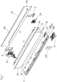
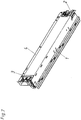
- Fig. 1 shows an exploded perspective view of a container rail 1 and attached to it a drawer side wall 5.
- the drawer side wall 5 is made in two parts in this example and consists of an inner wall 5a and an outer wall 5b.
- the container rail 1 has a substantially S-shaped or Z-shaped section in cross-section. This section forms in particular a support web 6, which comprises the two height-wise different support legs 6a and 6b. On the support web 6, a correspondingly shaped drawer bottom of a drawer container can be placed and connected to the container rail 1.
- the drawer container formed thereby can be connected, for example, with a pre-assembled in the furniture carcass drawer extension.
- a coupling element 19 to be fastened to the container rail 1 is provided, with which the drawer container attached to the drawer extension guide can be connected to the rails of the drawer extension guide, the rails of the drawer extension guide being below the support leg 6b.
- the container rail 1 has a leg 17 bent downwards along the outer longitudinal edge and facing downwards.
- the lower end portion 8 of the inner wall 5a can be attached. This attachment can be done for example by clinching, gluing, riveting, screwing, welding, etc.
- the inner wall 5a can be connected to a stabilizing device 4 in the region of its upper longitudinal edge.
- the stabilization device 4 is formed in this example as a U-shaped stabilizing rail 4, which engage in a corresponding groove 11 of the inner wall 5a and can be glued to the inner wall 5a, for example, to cause no significant noise in typical situations of use of a drawer comprising this arrangement.
- an adhesive e.g. a two-component adhesive are used.
- an attachment 2 is provided, on which, for example, a front fitting assembly 21 can be arranged, in order subsequently to be able to attach a drawer front panel to the front fitting assembly 21. Since the end portion 8 of the inner wall 5a in this example has recesses in the front and rear end region of the inner wall 5a, the attachment 2 can be fastened directly to the container rail 1 and to the stabilizing rail 4, for example by welding. This is particularly advantageous if both container rail 1 and attachment 2 and stabilizing rail 4 are made of steel and the inner wall 5a is not made of steel.
- the front fitting assembly 21 may include a plurality of adjusting means for changing the position of the drawer front panel relative to the container rail 1.
- a cover 20 is provided, which is releasably securable to the inner wall 5a, for example by a snap connection.
- an attachment 3 is provided on which, for example, a rear wall holder 12 can be attached for fastening a drawer rear wall.
- the two essays 2 and 3 can, as mentioned above, connected to the container rail 1 and the stabilizing device 4-preferably welded-so that a stable frame formed by container rail 1, attachments 2 and 3 and stabilizing device 4 results.
- This stable frame serves to absorb forces which are introduced, for example, via the drawer front panel.
- the inner wall 5a has in this example in the region of its upper, outer longitudinal edge on an S-shaped bent portion which can serve as a pivot bearing 10 for a corresponding hook-shaped portion 18 of the upper longitudinal edge of the outer wall 5b.
- the hook-shaped portion 18 of the outer wall 5b can be suspended in the pivot bearing 10, and subsequently the outer wall 5b can be pivoted relative to the inner wall 5a.
- the outer wall 5b has in this example in the lower end region on a U-shaped bent end portion 9, to which an S-shaped bent portion connects, which serves as a locking part 7b.
- this latching part 7b can engage on a correspondingly shaped latching receptacle 7a above the end section 8 of the inner wall 5a, whereby the outer wall 5b can be fastened to the inner wall 5a.
- the locking portion 7a of the inner wall 5a and the locking portion 7b of the outer wall 5b form a mechanical locking connection 7.
- the end portion 8 of the inner wall 5a simultaneously serves as a stop for the end portion 9 of the outer wall 5b, so that after locking by means of locking connection 7 of the end portion 9 of the outer wall 5b at least partially abuts the end portion 8 of the inner wall 5a.
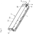
- Fig. 2 shows a perspective view of a container rail 1 with attached drawer side wall 5 according to Fig. 1 , Between the inner wall 5a and the outer wall 5b there is an attached to the inner wall 5a and hidden in this illustration by the inner wall 5a and thus not visible Stabilization device 4, which together with the container rail 1 and the essays 2 and 3 (also not visible here), which are connected to both the container rail 1 and with the stabilizing device 4, forms a force-absorbing frame.
- a rear wall bracket 12 is mounted for attachment of a drawer rear wall.
- the adjustment of the attachment 2 arranged on the front fitting assembly 21 are optically covered with a cover 20.
- a coupling element 19 is provided, which is already fastened to the container rail 1 in this illustration.
- the Fig. 3 to 6 show a proposed assembly process to connect an inner wall 5a with a Be concisenisschiene 1.
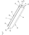
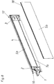
- Fig. 3 shows an inner wall 5a and a stabilizer 4 to be attached thereto, which is formed in this example as a substantially U-shaped stabilizing rail 4, in a perspective interior view, that is, in a perspective view obliquely from above on the front side of the inner wall 5a.
- the inner wall 5a has in this example a wall part 22, to which in the upper end region of the wall part 22 a substantially U-shaped in cross-section cover 23 connects.
- This cover 23 is formed by a along the upper longitudinal edge of the wall portion 22 bent portion and at the same time represents the upper edge of the drawer side wall 5.
- the cover 23 is continued as a substantially S-shaped profile section, which serves as a pivot bearing 10 for one with the inner wall 5a can be used to connect outer wall 5b.
- a vertical profile section 24 adjoins the S-shaped profile section, wall section 22, vertical profile section 24 and cover 23 forming a substantially U-shaped groove 11 into which the U-shaped stabilizing rail 4 can engage.
- the stabilizing rail 4 additionally has a plurality of elevations 13, which are formed starting from the inner profile side wall 25 of the stabilizing rail 4 in the direction of the outer profile side wall 26.
- the vertical profile section 24 of the inner wall 5a can be clamped between the outer profile side wall 26 and the elevations 13 on the inner profile side wall 25, as a result of which a positionally stable and essentially play-free mounting of the inner wall 5a on the stabilizing rail 4 can be achieved.
- comprehensive drawer can be additionally introduced between the inner profile side wall 25 of the stabilizing rail 4 and the wall portion 22 of the inner wall 5a, preferably elastic, damping device, for example in the form of an adhesive strip in the adhesive area 15th (please refer Fig. 9c ).
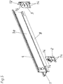
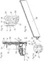
- Fig. 4 shows the arrangement according to Fig. 3 , wherein the stabilizing rail 4 is already preassembled on the inner wall 5a.
- a horizontally projecting abutment portion 27 connects, which has a substantially perpendicular protruding nose at the outer end, which serves as a latching receptacle 7a to lock the inner wall 5a with the outer wall 5b .
- the latching receptacle 7a is adjoined by a vertical profile section, which forms the end section 8 of the inner wall 5a.
- the inner wall 5 a can be connected to the vertical leg 17 of the container rail 1.
- the connection between container rail 1 and inner wall 5a is preferably carried out by clinching.
- the end portion 8 has recesses. These recesses serve to ensure that, in the further assembly sequence, corresponding attachments 2, 3 for the attachment of drawer front panel and drawer rear wall, which are to be connected to the stabilizing rail 4, can also be connected directly to the container rail 1.
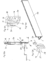
- Fig. 5 shows the arrangement according to Fig. 4 , wherein the inner wall 5a is already connected to the container rail 1, from an external perspective view, that is, in a perspective view obliquely from above on the rear side of the inner wall 5a.
- the end portion 8 of the inner wall 5a has corresponding recesses in the front and rear end region.
- the attachments 2 and 3 to be connected directly to the container rail 1 at their lower end regions.
- the essays 2 and 3 in this example corresponding Attachment points 14 on which the essays 2 and 3 can be welded to the container rail 1, for example.
- the attachments 2 and 3 have further fastening points 14, on which the attachments 2 and 3 can be connected to the stabilizing rail 4, for example by welding.
- Fig. 6 shows the arrangement according to Fig. 5 , wherein the essays 2 and 3 are already connected to the container rail 1 and the stabilizing rail 4. This results in a stable frame, formed from container rail 1, front attachment 2, stabilizing rail 4 and rear attachment 3. This frame forms a supporting framework, which can absorb in particular forces acting on the front attachment 2, on which a not shown here Drawer front panel can be attached.
- Fig. 7 shows this frame according to Fig. 6 in a perspective interior view, wherein the inner wall 5a is hidden, so that the frame is visible.
- container rail 1 front attachment 2, rear attachment 3 and stabilizing rail 4 made of steel
- the essays 2 and 3 are welded to the container rail 1 and the stabilizing rail 4, respectively.
- An attachment of the attachments 2 and 3 on the container rail 1 and the stabilizing rail 4 can of course be done in other ways, for example by riveting, screwing or clinching.
- the 8 to 12 show a proposed assembly procedure to connect an outer wall 5b with an inner wall 5a.
- Fig. 8 shows the arrangement according to Fig. 6 and an outer wall 5b to be connected to the inner wall 5a.
- the inner wall 5a is already connected in this example with a container rail 1 and by means of the inner wall 5a pre-mounted stabilizing rail 4 with the essays 2 and 3, so that a stable assembly consisting of container rail 1, inner wall 5a with attached stabilizing rail 4 and with the Container rail 1 and the stabilizing rail 4 connected essays 2 and 3 results.
- the inner wall 5a has along the outer upper longitudinal edge on a substantially S-shaped bent portion which serves as a pivot bearing 10 for the outer wall 5b.
- Fig. 9a shows the hinged in the pivot bearing 10 of the inner wall 5a outer wall 5b in a perspective exterior view
- Fig. 9b the same arrangement in a cross-sectional view
- Fig. 9c the designated A, circularly marked, area of Fig. 9b in an enlarged view.
- the outer wall 5b has a hook-shaped inwardly bent portion 18 along the upper longitudinal edge, through which the outer wall 5b can be suspended in the pivot bearing 10 of the inner wall 5a.
- the lower edge of the outer wall 5b is formed in this example by a deep, U-shaped groove, which simultaneously represents the end portion 9 of the outer wall 5b.
- a substantially S-shaped portion connects, which forms the locking part 7b of the outer wall 5b.
- This latching part 7b can interact with the nose-shaped latching receptacle 7a of the inner wall 5a, so that the latching part 7b of the outer wall 5b can engage the latching receptacle 7a of the inner wall 5a and thus the outer wall 5b can be fastened to the inner wall 5a.
- FIG. 10a, 10b and 10c show representations according to Fig. 9a, 9b and 9c , wherein the outer wall 5b was pivoted to the stop of the locking part 7b on the locking receptacle 7a of the inner wall 5a.
- Fig. 10d shows the designated B, circularly marked, area of Fig. 10b in an enlarged view. It can be seen that the detent connection 7 formed from latching receptacle 7a of the inner wall 5a and latching part 7b of the outer wall 5b is not latched yet.
- elastic damping devices may additionally be introduced between the inner wall 5a and the outer wall 5b, for example in the form of adhesive strips in the adhesive areas 16 in the region of the pivot bearing 10 and the latching connection 7 ,
- FIG. 11a to 11d show representations according to Fig. 10a to 10d , wherein the outer wall 5b has been fixed by means of latching connection 7 on the inner wall 5a.
- Fig. 12a to 12d show the same representations, for reasons of clarity, the rear wall bracket 12 and the coupling member 19 have been hidden.
- the outer wall 5b has been pivoted to the latching receptacle 7a of the inner wall 5a until the latching part 7b engages.
- the end portion 8 of the inner wall 5a at the same time forms a stop for the end portion 9 of the outer wall 5b, so that the end portion 9 of the outer wall 5b at least partially abuts the end portion 8 of the inner wall 5a after the latching connection 7 becomes effective.
- the end portion 8 of the inner wall 5a is approximately flush with the lower edge of the vertical leg 17 of the container rail 1, wherein the end portion 9 of the outer wall 5b projects beyond the lower end of the end portion 8 of the inner wall 5a.
- the outer wall 5b can additionally be used as a decorative element, since it can hide the arrangement behind it.
- a Aus rehabilitationschutz against unintentional release of the outer wall 5b of the inner wall 5a can be achieved. If an outward force F acts on the end portion 9 of the outer wall 5b, this results in an even stronger locking of the locking connection 7 instead of releasing it, whereby an unintentional unhooking of the outer wall 5b from the inner wall 5a can be avoided.
- the container rail 1 is provided for attachment to the underside of a drawer bottom.
- Fig. 12b can be seen, while the outer edge of the drawer bottom can be bordered by the horizontal abutment portion 27, the end portion 8 of the inner wall 5a and the container rail 1.
- the horizontal contact portion 27 can rest on the drawer bottom, whereby the locking receptacle 7a can be additionally stiffened.
- a directed towards the outside on the end portion 9 of the outer wall 5b force F leads to a pivoting of the end portion 9 about an imaginary axis of rotation D, which is located in the region of the locking receptacle 7a of the inner wall 5a.
- the nose-shaped portion 28 of the locking part 7b of the outer wall 5b is thereby pressed down against the locking receptacle 7a and the horizontal abutment portion 27 of the inner wall 5a (see Fig. 12d ).
- the inner wall 5a and the outer wall 5b may consist, for example, of a sheet of steel or aluminum, and the above-described special and multifunctional shapes of inner wall 5a and outer wall 5b can be realized by a sheet metal bending process.
Landscapes
- Drawers Of Furniture (AREA)
Description
- Die Erfindung betrifft eine Schubladenseitenwand mit einer Innenwand und einer Außenwand, wobei die Schubladenseitenwand mit einem Schubladenschienensystem zu verbinden ist, das zumindest großteils innerhalb der Innenwand liegt, wobei die Innenwand und die Außenwand über eine mechanische Rastverbindung miteinander verbindbar sind, wobei die Innenwand und die Außenwand in Montageposition unterhalb der Rastverbindung jeweils Endabschnitte aufweisen.
- Mehrteilig ausgeführte Schubladenseitenwände bzw. Schubladenzargen sind im Stand der Technik bereits bekannt. Sie bestehen typischerweise aus einer Innenwand und einer Außenwand, welche mit der Innenwand zu verbinden ist. So zeigt die
DE 41 23 213 A1 eine Seitenzarge einer Schublade bestehend aus zwei Profilelementen. Ein oberer Rand des ersten Profilelements ist nach außen abgebogen und nach unten gezogen, wobei dieser eingezogene Rand ein als nach unten offene Nut ausgebildetes Halteprofil für den oberen Rand des zweiten Profilelements bildet. Ein am ersten Profilelement angeordneter Begrenzungssteg zur Beabstandung der Profilelemente wirkt mit einem Schnappprofil des zweiten Profilelements zusammen, um die beiden Profilelemente zu verbinden. Auch dieEP 1 614 369 A1 zeigt eine doppelwandige Schubladenzarge, welche zwei Wandteile umfasst. Die beiden Wandteile können durch eine mechanische Rastverbindung verbunden werden, wobei die Rastverbindung derart ausgebildet ist, dass die beiden Wandteile in einfacher und rascher Art wieder getrennt werden können. Insbesondere sind dabei die Endabschnitte der beiden Wandteile unterhalb der Rastverbindung voneinander beabstandet. Dies ist insofern nachteilig, als dadurch auch leicht ein unbeabsichtigtes Lösen der Rastverbindung erfolgen kann, beispielsweise dadurch, dass man sich am Endabschnitt des äußeren Wandteils verhakt und somit den äußeren Wandteil vom inneren Wandteil ablöst. DieDE 202 03 551 U1 zeigt ebenfalls eine doppelwandige Schubladenzarge, wobei die beiden Wandteile in den oberen Endbereichen durch einen Halteteil und in den unteren Endbereichen durch eine Nut- und Federverbindung miteinander verbunden werden können. Auch hier sind die Endabschnitte der Wandteile unterhalb der Nut- und Federverbindung voneinander beabstandet, sodass man leicht unbeabsichtigt am Endabschnitt des äußeren Wandteils einhaken und den äußeren Wandteil vom inneren Wandteil lösen kann. - Die Erfindung hat es sich daher zur Aufgabe gemacht, eine gegenüber dem Stand der Technik verbesserte Schubladenseitenwand anzugeben. Insbesondere soll ein unbeabsichtigtes Lösen der Rastverbindung und somit ein unbeabsichtigtes Lösen der Außenwand von der Innenwand verhindert werden.
- Dies wird erfindungsgemäß durch die Merkmale des Patentanspruchs 1 gelöst. Weitere vorteilhafte Ausgestaltungen der Erfindung sind in den abhängigen Unteransprüchen angegeben.
- Gemäß der Erfindung ist also vorgesehen, dass der Endabschnitt der Innenwand und der Endabschnitt der Außenwand zumindest abschnittsweise aneinander anliegen, wobei der Endabschnitt der Außenwand über den Endabschnitt der Innenwand hinausragt, und dass die Innenwand eine Rastaufnahme aulweist, in die ein Rastteil der Außenwand einrastbar ist, wobei der Rastteil bei einem Abheben des nach unten vorstehenden Endabschnitts der Außenwand vom Endabschnitt der Innenwand in die Rastaufnahme der Innenwand gedrückt wird und damit ein Lösen der Rastverbindung verhindert.
- Dadurch, dass der Endabschnitt der Außenwand zumindest abschnittsweise am Endabschnitt der Innenwand anliegt, wird ein unbeabsichtigtes Lösen der Außenwand von der Innenwand erschwert, da es dadurch keinen Bereich mehr zwischen dem Endabschnitt der Innenwand und dem Endabschnitt der Außenwand gibt, in den man unbeabsichtigt einhaken und die Rastverbindung lösen kann. Durch ein leichtes Überstehen des Endabschnitts der Außenwand über den Endabschnitt der Innenwand kann darüber hinaus eine optische Verdeckung der Innenwand durch die Außenwand erreicht werden.
- Die Rastverbindung ist dadurch gebildet, dass die Innenwand eine Rastaufnahme aufweist, in die ein Rastteil der Außenwand einrastbar ist. Sowohl Rastaufnahme als auch Rastteil können dabei je einen profilierten Schenkel aufweisen, der sich über einen Teil der Länge der Schubladenseitenwand erstreckt. Die Profilierung kann dabei jeweils - im Querschnitt - im Wesentlichen S-förmig oder Z-förmig ausgebildet sein. Solche Profilierungen ermöglichen insbesondere eine im Wesentlichen formschlüssige Verbindung des Rastteils der Außenwand mit der Rastaufnahme der Innenwand.
- Die Rastverbindung zwischen Innenwand und Außenwand ist dabei derart ausgebildet, dass der Rastteil bei einem Abheben des nach unten vorstehenden Endabschnitts der Außenwand vom Endabschnitt der Innenwand in die Rastaufnahme der Innenwand gedrückt wird und damit ein Lösen der Rastverbindung verhindert. Wenn bei einer solchen Ausführung eine nach außen gerichtete Kraft auf den Endabschnitt der Außenwand einwirkt, so führt dies zu einer noch stärkeren Verrastung der Rastverbindung anstatt diese zu lösen, wodurch ein unbeabsichtigtes Lösen der Außenwand von der Innenwand vermieden werden kann.
- Bei einer möglichen Weiterbildung der Erfindung kann vorgesehen sein, dass die Rastverbindung mit einem Abstand oberhalb der untersten Enden der Endabschnitte angeordnet ist. Wenn eine solche Schubladenseitenwand mit einer Behältnisschiene zu verbinden ist, ermöglicht diese Ausführung eine Lagerung eines Schubladenbodens zwischen der Behältnisschiene und der Rastverbindung. Dabei kann beispielsweise der Abstand zwischen dem untersten Ende des Endabschnitts der Innenwand und der Rastaufnahme der Innenwand ca. 10-30% der Höhe der Schubladenseitenwand betragen.
- Wenn sich an die Rastaufnahme ein im Wesentlichen horizontaler Anlageabschnitt anschließt, wobei der horizontale Anlageabschnitt innen an einem Schubladenboden aufliegt, so kann der äußere Rand des Schubladenbodens durch den horizontalen Anlageabschnitt, den Endabschnitt der Innenwand und die Behältnisschiene eingefasst werden. Dabei kann der horizontale Anlageabschnitt auf dem Schubladenboden aufliegen, wodurch die Rastaufnahme zusätzlich versteift werden kann. Eine nach außen auf den Endabschnitt der Außenwand gerichtete Kraft führt zu einer Verschwenkung des Endabschnitts um eine gedachte Drehachse, welche sich im Bereich der Rastaufnahme der Innenwand befindet. Der Rastteil der Außenwand wird dabei nach unten gegen die Rastaufnahme und den horizontalen Anlageabschnitt der Innenwand gedrückt. Dadurch, dass der horizontale Anlageabschnitt am Schubladenboden anliegt, kann die Rastaufnahme jedoch nicht nach unten ausweichen, wodurch sich die Rastverbindung nicht lösen kann und somit eine Lösung der Außenwand von der Innenwand verhindert werden kann.
- In einer bevorzugten Ausführungsform der Erfindung kann vorgesehen sein, dass die Innenwand im Bereich seiner oberen Längskante ein Schwenklager aufweist, in welches die Außenwand einhängbar und relativ zur Innenwand schwenkbar ist. In einer besonders einfach zu fertigenden Variante weist dabei das Schwenklager eine im Wesentlichen U-förmige Gestalt auf.
- Gemäß einer weiteren Ausgestaltung kann die Schubladenseitenwand eine längs verlaufende Nut aufweisen. Wenn dabei die Nut im Bereich der oberen Längskante der Innenwand verläuft, kann die Innenwand besonders einfach auf einer Stabilisierungseinrichtung gelagert werden. Eine solche Stabilisierungseinrichtung kann z.B. zwischen im vorderen und hinteren Endbereich einer Behältnisschiene zu befestigenden Aufsätzen vorgesehen sein, an welche wiederum eine Schubladenfrontblende und eine Schubladenrückwand befestigbar sind. Eine solche Anordnung aus Behältnisschiene, den zwei an der Behältnisschiene angeordneten Aufsätzen und die Stabilisierungseinrichtung ergibt einen stabilen Rahmen, welcher insbesondere Kräfte, die beispielsweise über die Schubladenfrontblende oder über die Schubladenrückwand in diese Anordnung eingebracht werden, abfangen kann, unabhängig davon, ob eine Schubladenseitenwand vorhanden ist oder nicht. Eine an diesem Rahmen zu befestigende Schubladenseitenwand wird keinen wesentlichen Krafteinwirkungen mehr ausgesetzt und kann dadurch beispielsweise auch sehr dünn ausgeführt werden. Eine sehr dünne Schubladenseitenwand wiederum führt dazu, dass die lichte Breite eines mit dieser Anordnung gebildeten Schubladenbehälters entsprechend vergrößert werden kann, wodurch sich ebenfalls der benutzbare Stauraum im Schubladenbehälter vergrößert. Außerdem können dadurch die Schubladenseitenwände auch als reine Verkleidungselemente ausgeführt sein und aus Werkstoffen bestehen, welche einer Krafteinwirkung der vorbeschriebenen Art nicht standhalten würden.
- Gemäß einer bevorzugten Ausführungsform der Erfindung kann vorgesehen sein, dass der Endabschnitt der Außenwand durch einen im Wesentlichen U-förmigen Abschnitt gebildet ist. Diese Ausgestaltung bietet sich insbesondere an, wenn die Innenwand und die Außenwand beispielsweise aus einem Stahl- oder Aluminiumblech bestehen, wodurch spezielle Formgebungen von Innenwand und Außenwand durch einen Blechbiegeprozess realisiert werden können.
- Weitere Einzelheiten und Vorteile der vorliegenden Erfindung werden anhand der Figurenbeschreibung unter Bezugnahme auf die in den Zeichnungen dargestellten Ausführungsbeispiele im Folgenden näher erläutert. Darin zeigen:
- Fig. 1
- eine perspektivische Explosionsdarstellung einer Behältnisschiene mit einer daran zu befestigenden Schubladenseitenwand,
- Fig. 2
- eine perspektivische Darstellung einer Behältnisschiene mit daran befestigter Schubladenseitenwand gemäß
Fig. 1 , - Fig. 3
- eine mit einer Innenwand zu befestigende Stabilisierungseinrichtung,
- Fig. 4
- eine Innenwand mit daran befestigter Stabilisierungseinrichtung, welche mit einer Behältnisschiene zu verbinden ist,
- Fig. 5
- mit der Behältnisschiene und der Stabilisierungseinrichtung gemäß
Fig. 4 zu verbindende Aufsätze, an welchen eine Schubladenfrontblende und eine Schubladenrückwand angebracht werden können, - Fig. 6
- eine perspektivische Darstellung gemäß
Fig. 5 mit an der Behältnisschiene und der Stabilisierungseinrichtung befestigten Aufsätzen, - Fig. 7
- eine Detaildarstellung des Stabilisierungsrahmens bestehend aus der Behältnisschiene, den beiden Aufsätzen und der Stabilisierungseinrichtung,
- Fig. 8
- eine Anordnung gemäß
Fig. 6 mit daran zu befestigender Außenwand, - Fig. 9a - 9c
- verschiedene Ansichten gemäß
Fig. 8 mit einer an der Innenwand eingehängten Außenwand, - Fig. 10a - 10d
- die Außenwand gemäß
Fig. 9 in einer weiter zur Innenwand verschwenkten Position, - Fig. 11a - 11d
- die Außenwand gemäß
Fig. 10 in einer mit der Innenwand verrasteten Position, und - Fig. 12a - 12d
- verschiedene Ansichten gemäß
Fig. 11a bis 11d , wobei aus Gründen der Übersichtlichkeit verschiedene Elemente ausgeblendet sind. -
Fig. 1 zeigt eine perspektivische Explosionsdarstellung einer Behältnisschiene 1 und einer daran zu befestigenden Schubladenseitenwand 5. Die Schubladenseitenwand 5 ist in diesem Beispiel zweiteilig ausgeführt und besteht aus einer Innenwand 5a und einer Außenwand 5b. Die Behältnisschiene 1 weist im Querschnitt einen im Wesentlichen S-förmigen bzw. Z-förmigen Abschnitt auf. Dieser Abschnitt bildet insbesondere einen Auflagesteg 6, welcher die zwei höhenmäßig unterschiedlichen Auflageschenkel 6a und 6b umfasst. Auf dem Auflagesteg 6 kann ein entsprechend geformter Schubladenboden eines Schubladenbehälters aufgesetzt und mit der Behältnisschiene 1 verbunden werden. Nach weiterer erfolgter Montage von Schubladenseitenwänden 5 an den Behältnisschienen 1 sowie Schubladenfrontblende und Schubladenrückwand an den Aufsätzen 2 und 3 kann der dadurch gebildete Schubladenbehälter beispielsweise mit einer im Möbelkorpus vormontierten Schubladenausziehführung verbunden werden. Dafür ist ein an der Behältnisschiene 1 zu befestigendes Kupplungselement 19 vorgesehen, mit dem sich der auf die Schubladenausziehführung aufgesetzte Schubladenbehälter mit den Schienen der Schubladenausziehführung verbinden lässt, wobei sich die Schienen der Schubladenausziehführung unterhalb des Auflageschenkels 6b befinden. - Am äußeren Rand weist die Behältnisschiene 1 einen entlang der äußeren Längskante umgebogenen, nach unten weisenden, Schenkel 17 auf. An diesem vertikalen Schenkel 17 der Behältnisschiene 1 kann der untere Endabschnitt 8 der Innenwand 5a befestigt werden. Diese Befestigung kann beispielsweise durch Clinchen, Kleben, Vernieten, Verschrauben, Verschweißen etc. erfolgen. Die Innenwand 5a kann im Bereich Ihrer oberen Längskante mit einer Stabilisierungseinrichtung 4 verbunden werden. Die Stabilisierungseinrichtung 4 ist in diesem Beispiel als U-förmige Stabilisierungsschiene 4 ausgebildet, welche in eine korrespondierende Nut 11 der Innenwand 5a eingreifen und mit der Innenwand 5a beispielsweise verklebt werden kann, um in typischen Gebrauchssituationen einer diese Anordnung umfassende Schublade keine nennenswerte Geräuschentwicklung zu verursachen. Als Klebstoff kann dabei z.B. ein Zweikomponentenkleber zum Einsatz kommen.
- Im vorderen Endbereich der Behältnisschiene 1 ist ein Aufsatz 2 vorgesehen, an welchem beispielsweise eine Frontbeschlagsbaugruppe 21 angeordnet werden kann, um in weiterer Folge an der Frontbeschlagsbaugruppe 21 eine Schubladenfrontblende befestigen zu können. Da der Endabschnitt 8 der Innenwand 5a in diesem Beispiel im vorderen und hinteren Endbereich der Innenwand 5a Ausnehmungen aufweist, kann der Aufsatz 2 direkt an der Behältnisschiene 1 und an der Stabilisierungsschiene 4, beispielsweise durch Schweißen, befestigt werden. Dies ist insbesondere dann vorteilhaft, wenn sowohl Behältnisschiene 1 als auch Aufsatz 2 als auch Stabilisierungsschiene 4 aus Stahl bestehen und die Innenwand 5a nicht aus Stahl besteht. Die Frontbeschlagsbaugruppe 21 kann eine Mehrzahl von Verstelleinrichtungen aufweisen, um die Lage der Schubladenfrontblende relativ zur Behältnisschiene 1 zu verändern. Solche Verstelleinrichtungen werden typischerweise mittels Schraubenzieher durch entsprechende Ausnehmungen der Innenwand 5a hindurch bedient. Um nach erfolgter Anpassung die Verstelleinrichtungen optisch abzudecken, ist eine Abdeckung 20 vorgesehen, die an der Innenwand 5a lösbar befestigbar ist, z.B. durch eine Schnappverbindung.
- Im Bereich des hinteren Endes der Behältnisschiene 1 ist ein Aufsatz 3 vorgesehen, an welchem beispielsweise ein Rückwandhalter 12 zur Befestigung einer Schubladenrückwand angebracht werden kann. Die beiden Aufsätze 2 und 3 können wie oben erwähnt mit der Behältnisschiene 1 und der Stabilisierungseinrichtung 4 verbunden - vorzugsweise verschweißt - werden, sodass sich ein stabiler Rahmen, gebildet aus Behältnisschiene 1, Aufsätze 2 und 3 und Stabilisierungseinrichtung 4, ergibt. Dieser stabile Rahmen dient dazu, Kräfte aufzunehmen, welche beispielsweise über die Schubladenfrontblende eingebracht werden.
- Die Innenwand 5a weist in diesem Beispiel im Bereich seiner oberen, äußeren Längskante einen S-förmig gebogenen Abschnitt auf, welcher als Schwenklager 10 für einen entsprechend hakenförmig gebogenen Abschnitt 18 der oberen Längskante der Außenwand 5b dienen kann. Der hakenförmige Abschnitt 18 der Außenwand 5b kann in das Schwenklager 10 eingehängt werden, und in weiterer Folge kann die Außenwand 5b relativ zur Innenwand 5a verschwenkt werden. Die Außenwand 5b weist in diesem Beispiel im unteren Endbereich einen U-förmig gebogenen Endabschnitt 9 auf, an welchen sich ein S-förmig gebogener Abschnitt anschließt, welcher als Rastteil 7b dient. Dieser Rastteil 7b kann nach entsprechender Verschwenkung der Außenwand 5b zur Innenwand 5a an einer entsprechend geformten Rastaufnahme 7a oberhalb des Endabschnitts 8 der Innenwand 5a einrasten, wodurch die Außenwand 5b an der Innenwand 5a befestigt werden kann. Die Rastaufnahme 7a der Innenwand 5a und der Rastteil 7b der Außenwand 5b bilden eine mechanische Rastverbindung 7. Der Endabschnitt 8 der Innenwand 5a dient dabei gleichzeitig als Anschlag für den Endabschnitt 9 der Außenwand 5b, sodass nach erfolgter Verrastung mittels Rastverbindung 7 der Endabschnitt 9 der Außenwand 5b zumindest abschnittsweise am Endabschnitt 8 der Innenwand 5a anliegt.
-
Fig. 2 zeigt eine perspektivische Darstellung einer Behältnisschiene 1 mit daran befestigter Schubladenseitenwand 5 gemäßFig. 1 . Zwischen Innenwand 5a und Außenwand 5b befindet sich eine an der Innenwand 5a angebrachte und in dieser Darstellung durch die Innenwand 5a verdeckte und somit nicht sichtbare Stabilisierungseinrichtung 4, welche gemeinsam mit der Behältnisschiene 1 und den Aufsätzen 2 und 3 (hier ebenfalls nicht sichtbar), welche sowohl mit der Behältnisschiene 1 als auch mit der Stabilisierungseinrichtung 4 verbunden sind, einen kräfteaufnehmenden Rahmen bildet. Am hinteren Aufsatz 3 ist ein Rückwandhalter 12 zur Befestigung einer Schubladenrückwand angebracht. Die Verstelleinrichtungen der am Aufsatz 2 angeordneten Frontbeschlagsbaugruppe 21 sind mit einer Abdeckung 20 optisch abgedeckt. Zur Verbindung der Behältnisschiene 1 mit einer Schubladenausziehführung ist ein Kupplungselement 19 vorgesehen, welches in dieser Darstellung bereits an der Behältnisschiene 1 befestigt ist. - Die
Fig. 3 bis 6 zeigen einen vorgeschlagenen Montageablauf, um eine Innenwand 5a mit einer Behältnisschiene 1 zu verbinden. -
Fig. 3 zeigt eine Innenwand 5a und eine daran zu befestigende Stabilisierungseinrichtung 4, welche in diesem Beispiel als im Wesentlichen U-förmige Stabilisierungsschiene 4 ausgebildet ist, in einer perspektivischen Innenansicht, das heißt in einer perspektivischen Ansicht von schräg oben auf die Vorderseite der Innenwand 5a. Die Innenwand 5a weist in diesem Beispiel einen Wandteil 22 auf, an den sich im oberen Endbereich des Wandteils 22 ein im Querschnitt im Wesentlichen U-förmiger Deckel 23 anschließt. Dieser Deckel 23 ist dabei durch einen entlang der oberen Längskante des Wandteils 22 umgebogenen Abschnitt gebildet und stellt gleichzeitig den oberen Rand der Schubladenseitenwand 5 dar. Der Deckel 23 ist als im Wesentlichen S-förmiger Profilabschnitt fortgeführt, welcher als Schwenklager 10 für eine mit der Innenwand 5a zu verbindende Außenwand 5b dienen kann. An den S-förmigen Profilabschnitt schließt ein senkrechter Profilabschnitt 24 an, wobei Wandteil 22, senkrechter Profilabschnitt 24 und Deckel 23 eine im Wesentlichen U-förmige Nut 11 bilden, in die die U-förmigen Stabilisierungsschiene 4 eingreifen kann. - Die Stabilisierungsschiene 4 weist in diesem Beispiel zusätzlich eine Mehrzahl von Erhebungen 13 auf, welche ausgehend von der inneren Profilseitenwand 25 der Stabilisierungsschiene 4 in Richtung der äußeren Profilseitenwand 26 ausgebildet sind. Dadurch kann der senkrechte Profilabschnitt 24 der Innenwand 5a zwischen der äußeren Profilseitenwand 26 und den Erhebungen 13 an der inneren Profilseitenwand 25 eingeklemmt werden, wodurch sich eine lagestabile und im Wesentlichen spielfreie Lagerung der Innenwand 5a auf der Stabilisierungsschiene 4 erzielen lässt. Als zusätzliche Befestigung und als Maßnahme zu einer Geräuscheindämmung in typischen Gebrauchssituationen einer diese Anordnung umfassende Schublade kann zusätzlich zwischen der inneren Profilseitenwand 25 der Stabilisierungsschiene 4 und dem Wandteil 22 der Innenwand 5a eine, vorzugsweise elastische, Dämpfvorrichtung eingebracht werden, beispielsweise in Form eines Klebstoffstreifens im Klebebereich 15 (siehe
Fig. 9c ). -
Fig. 4 zeigt die Anordnung gemäßFig. 3 , wobei die Stabilisierungsschiene 4 an der Innenwand 5a bereits vormontiert ist. An den unteren Endbereich des Wandteils 22 der Innenwand 5a schließt sich in diesem Beispiel ein horizontal abstehender Anlageabschnitt 27 an, der am äußeren Ende eine im Wesentlichen senkrecht abstehende Nase aufweist, welche als Rastaufnahme 7a dient, um die Innenwand 5a mit der Außenwand 5b zu verrasten. An die Rastaufnahme 7a wiederum schließt sich ein senkrechter Profilabschnitt an, welcher den Endabschnitt 8 der Innenwand 5a bildet. Im Bereich dieses Endabschnitts 8 kann die Innenwand 5a mit dem vertikalen Schenkel 17 der Behältnisschiene 1 verbunden werden. Für den Fall, dass Behältnisschiene 1 und Innenwand 5a aus unterschiedlichen Materialien bestehen (z.B. kann die Behältnisschiene 1 aus Stahl und die Innenwand 5a aus Aluminium bestehen), erfolgt die Verbindung zwischen Behältnisschiene 1 und Innenwand 5a vorzugsweise durch Clinchen. - Im vorderen und hinteren Endbereich der Innenwand 5a weist der Endabschnitt 8 Ausnehmungen auf. Diese Ausnehmungen dienen dazu, dass im weiteren Montageablauf entsprechende Aufsätze 2, 3 für die Befestigung von Schubladenfrontblende und Schubladenrückwand, welche mit der Stabilisierungsschiene 4 zu verbinden sind, auch direkt mit der Behältnisschiene 1 verbindbar sind.
-
Fig. 5 zeigt die Anordnung gemäßFig. 4 , wobei die Innenwand 5a bereits mit der Behältnisschiene 1 verbunden ist, aus einer perspektivischen Außenansicht, das heißt in einer perspektivischen Ansicht von schräg oben auf die Hinterseite der Innenwand 5a. Der Endabschnitt 8 der Innenwand 5a weist im vorderen und hinteren Endbereich entsprechende Ausnehmungen auf. Dadurch ist es möglich, dass die Aufsätze 2 und 3 an ihren unteren Endbereichen direkt mit der Behältnisschiene 1 verbunden werden können. Dafür weisen die Aufsätze 2 und 3 in diesem Beispiel entsprechende Befestigungsstellen 14 auf, an denen die Aufsätze 2 und 3 mit der Behältnisschiene 1 beispielsweise verschweißt werden können. An den oberen Endbereichen weisen die Aufsätze 2 und 3 weitere Befestigungsstellen 14 auf, an denen die Aufsätze 2 und 3 mit der Stabilisierungsschiene 4 verbunden werden können, beispielsweise durch Verschweißen. -
Fig. 6 zeigt die Anordnung gemäßFig. 5 , wobei die Aufsätze 2 und 3 bereits mit der Behältnisschiene 1 und der Stabilisierungsschiene 4 verbunden sind. Dadurch ergibt sich ein stabiler Rahmen, gebildet aus Behältnisschiene 1, vorderem Aufsatz 2, Stabilisierungsschiene 4 und hinterem Aufsatz 3. Dieser Rahmen bildet ein tragendes Gerüst, welches insbesondere Kräfte aufnehmen kann, die über den vorderen Aufsatz 2 einwirken, an welchem eine hier nicht gezeigte Schubladenfrontblende angebracht werden kann. -
Fig. 7 zeigt diesen Rahmen gemäßFig. 6 in einer perspektivischen Innenansicht, wobei die Innenwand 5a ausgeblendet ist, damit der Rahmen sichtbar ist. In diesem Beispiel bestehen Behältnisschiene 1, vorderer Aufsatz 2, hinterer Aufsatz 3 und Stabilisierungsschiene 4 aus Stahl, wobei die Aufsätze 2 und 3 mit der Behältnisschiene 1 und der Stabilisierungsschiene 4 jeweils verschweißt sind. Dadurch ergibt sich ein stabiler tragender Rahmen, welcher einwirkende Kräfte aufnehmen kann, unabhängig davon, ob eine Schubladenseitenwand mit diesem Rahmen verbunden ist oder nicht. Eine Befestigung der Aufsätze 2 und 3 an der Behältnisschiene 1 und der Stabilisierungsschiene 4 kann selbstverständlich aber auch auf andere Art erfolgen, z.B. durch Vernieten, Verschrauben oder Clinchen. - Die
Fig. 8 bis 12 zeigen einen vorgeschlagenen Montageablauf, um eine Außenwand 5b mit einer Innenwand 5a zu verbinden. -
Fig. 8 zeigt die Anordnung gemäßFig. 6 und eine Außenwand 5b, welche mit der Innenwand 5a zu verbinden ist. Die Innenwand 5a ist in diesem Beispiel bereits mit einer Behältnisschiene 1 und mittels an der Innenwand 5a vormontierter Stabilisierungsschiene 4 mit den Aufsätzen 2 und 3 verbunden, sodass sich eine stabile Baugruppe bestehend aus Behältnisschiene 1, Innenwand 5a mit daran befestigter Stabilisierungsschiene 4 und den mit der Behältnisschiene 1 und der Stabilisierungsschiene 4 verbundenen Aufsätzen 2 und 3 ergibt. Die Innenwand 5a weist entlang der äußeren oberen Längskante einen im Wesentlichen S-förmig gebogenen Abschnitt auf, welcher als Schwenklager 10 für die Außenwand 5b dient. In dieses Schwenklager 10 kann die Außenwand 5b mit ihrem hakenförmigen Abschnitt 18 eingehängt, in Richtung der Innenwand 5a verschwenkt und mit Hilfe eines durch die Perspektive der Darstellung nicht ersichtlichen Rastteils 7b mit der Rastaufnahme 7a der Innenwand 5a verrastet werden. -
Fig. 9a zeigt die im Schwenklager 10 der Innenwand 5a eingehängte Außenwand 5b in einer perspektivischen Außenansicht,Fig. 9b dieselbe Anordnung in einer Querschnittsdarstellung undFig. 9c den mit A bezeichneten, kreisförmig markierten, Bereich derFig. 9b in einer vergrößerten Darstellung. Die Außenwand 5b weist einen entlang der oberen Längskante hakenförmig nach innen gebogenen Abschnitt 18 auf, durch den die Außenwand 5b in das Schwenklager 10 der Innenwand 5a einhängbar ist. - Der untere Rand der Außenwand 5b ist in diesem Beispiel durch eine tiefe, U-förmige Rinne gebildet, welche gleichzeitig den Endabschnitt 9 der Außenwand 5b darstellt. An den Endabschnitt 9 schließt sich ein im Wesentlichen S-förmiger Abschnitt an, welcher den Rastteil 7b der Außenwand 5b bildet. Dieser Rastteil 7b kann mit der nasenförmigen Rastaufnahme 7a der Innenwand 5a zusammenwirken, sodass der Rastteil 7b der Außenwand 5b an der Rastaufnahme 7a der Innenwand 5a einrasten kann und damit die Außenwand 5b an der Innenwand 5a befestigbar ist.
-
Fig. 10a, 10b und 10c zeigen Darstellungen gemäßFig. 9a, 9b und 9c , wobei die Außenwand 5b bis zum Anschlag des Rastteils 7b an der Rastaufnahme 7a der Innenwand 5a verschwenkt wurde.Fig. 10d zeigt den mit B bezeichneten, kreisförmig markierten, Bereich derFig. 10b in einer vergrößerten Darstellung. Es ist zu erkennen, dass die aus Rastaufnahme 7a der Innenwand 5a und Rastteil 7b der Außenwand 5b gebildete Rastverbindung 7 noch nicht verrastet ist. Als zusätzliche Befestigung und als Maßnahme zu einer Geräuscheindämmung in Gebrauchsituationen einer diese Anordnung umfassende Schublade können zusätzlich zwischen der Innenwand 5a und der Außenwand 5b vorzugsweise elastische Dämpfvorrichtungen eingebracht werden, beispielsweise in Form von Klebstoffstreifen in den Klebebereichen 16 im Bereich des Schwenklagers 10 und der Rastverbindung 7. -
Fig. 11a bis 11d zeigen Darstellungen gemäßFig. 10a bis 10d , wobei die Außenwand 5b mittels Rastverbindung 7 an der Innenwand 5a befestigt wurde.Fig. 12a bis 12d zeigen dieselben Darstellungen, wobei aus Gründen der Übersichtlichkeit der Rückwandhalter 12 und das Kupplungselement 19 ausgeblendet wurden. In der dargestellten Anordnung wurde die Außenwand 5b bis zum Einrasten des Rastteils 7b an der Rastaufnahme 7a der Innenwand 5a verschwenkt. Der Endabschnitt 8 der Innenwand 5a bildet dabei gleichzeitig einen Anschlag für den Endabschnitt 9 der Außenwand 5b, sodass der Endabschnitt 9 der Außenwand 5b nach Wirksamwerden der Rastverbindung 7 zumindest abschnittsweise am Endabschnitt 8 der Innenwand 5a anliegt. - Im gezeigten Beispiel ist der Endabschnitt 8 der Innenwand 5a in etwa bündig mit der unteren Kante des vertikalen Schenkels 17 der Behältnisschiene 1, wobei der Endabschnitt 9 der Außenwand 5b über das untere Ende des Endabschnitts 8 der Innenwand 5a hinausragt. Dadurch kann einerseits ermöglicht werden, dass die Außenwand 5b zusätzlich als Dekorelement einsetzbar ist, da es die dahinterliegende Anordnung verdecken kann. Darüber hinaus kann durch diese Anordnung ein Aushängeschutz gegen unbeabsichtigtes Lösen der Außenwand 5b von der Innenwand 5a erzielt werden. Wenn eine nach außen gerichtete Kraft F auf den Endabschnitt 9 der Außenwand 5b einwirkt, so führt dies zu einer noch stärkeren Verrastung der Rastverbindung 7 anstatt diese zu lösen, wodurch ein unbeabsichtigtes Aushängen der Außenwand 5b von der Innenwand 5a vermieden werden kann.
- Die Behältnisschiene 1 ist zur Befestigung an der Unterseite eines Schubladenbodens vorgesehen. Wie insbesondere in
Fig. 12b zu erkennen ist, kann dabei der äußere Rand des Schubladenbodens durch den horizontalen Anlageabschnitt 27, den Endabschnitt 8 der Innenwand 5a und die Behältnisschiene 1 eingefasst werden. Dabei kann der horizontale Anlageabschnitt 27 auf dem Schubladenboden aufliegen, wodurch die Rastaufnahme 7a zusätzlich versteift werden kann. Eine nach außen auf den Endabschnitt 9 der Außenwand 5b gerichtete Kraft F führt zu einer Verschwenkung des Endabschnitts 9 um eine gedachte Drehachse D, welche sich im Bereich der Rastaufnahme 7a der Innenwand 5a befindet. Der nasenförmige Abschnitt 28 des Rastteils 7b der Außenwand 5b wird dabei nach unten gegen die Rastaufnahme 7a und den horizontalen Anlageabschnitt 27 der Innenwand 5a gedrückt (sieheFig. 12d ). Dadurch, dass bei vorhandenem Schubladenboden der horizontale Anlageabschnitt 27 am Schubladenboden anliegt, kann die Rastaufnahme 7a jedoch nicht nach unten ausweichen, wodurch sich die Rastverbindung 7 nicht lösen kann und somit eine Lösung der Außenwand 5b von der Innenwand 5a verhindert werden kann. - Für alle gezeigten Ausführungsbeispiele können die Innenwand 5a und die Außenwand 5b beispielsweise aus einem Stahl- oder Aluminiumblech bestehen und die vorbeschriebenen, speziellen und multifunktionalen Formgebungen von Innenwand 5a und Außenwand 5b können dabei durch einen Blechbiegeprozess realisiert werden.
Claims (11)
- Schubladenseitenwand (5) mit einer Innenwand (5a) und einer Außenwand (5b), wobei die Schubladenseitenwand (5) mit einem Schubladenschienensystem zu verbinden ist, das zumindest großteils innerhalb der Innenwand (5a) liegt, wobei die Innenwand (5a) und die Außenwand (5b) über eine mechanische Rastverbindung (7) miteinander verbindbar sind, wobei die Innenwand (5a) und die Außenwand (5b) in Montageposition unterhalb der Rastverbindung (7) jeweils Endabschnitte (8, 9) aufweisen, dadurch gekennzeichnet, dass der Endabschnitt (8) der Innenwand (5a) und der Endabschnitt (9) der Außenwand (5b) zumindest abschnittsweise aneinander anliegen, wobei der Endabschnitt (9) der Außenwand (5b) über den Endabschnitt (8) der Innenwand (5a) hinausragt, und dass die Innenwand (5a) eine Rastaufnahme (7a) aufweist, in die ein Rastteil (7b) der Außenwand (5b) einrastbar ist, wobei der Rastteil (7b) bei einem Abheben des nach unten vorstehenden Endabschnitts (9) der Außenwand (5b) vom Endabschnitt (8) der Innenwand (5a) in die Rastaufnahme (7a) der Innenwand (5a) gedrückt wird und damit ein Lösen der Rastverbindung (7) verhindert.
- Schubladenseitenwand nach Anspruch 1, dadurch gekennzeichnet, dass die Rastaufnahme (7a) einen profilierten Schenkel aufweist, der sich über einen Teil der Länge der Schubladenseitenwand (5) erstreckt.
- Schubladenseitenwand nach Anspruch 2, dadurch gekennzeichnet, dass die Rastaufnahme (7a) - im Querschnitt - im Wesentlichen S-förmig oder Z-förmig profiliert ist.
- Schubladenseitenwand nach einem der Ansprüche 1 bis 3, dadurch gekennzeichnet, dass sich an die Rastaufnahme (7a) ein im Wesentlichen horizontaler Anlageabschnitt (27) anschließt, wobei der horizontale Anlageabschnitt (27) innen an einem Schubladenboden aufliegt.
- Schubladenseitenwand nach einem der Ansprüche 1 bis 4, dadurch gekennzeichnet, dass der Rastteil (7b) einen profilierten Schenkel aufweist, der sich über einen Teil der Länge der Schubladenseitenwand (5) erstreckt.
- Schubladenseitenwand nach Anspruch 5, dadurch gekennzeichnet, dass der Rastteil (7b) - im Querschnitt - im Wesentlichen S-förmig oder Z-förmig profiliert ist.
- Schubladenseitenwand nach einem der Ansprüche 1 bis 6, dadurch gekennzeichnet, dass die Innenwand (5a) im Bereich seiner oberen Längskante ein Schwenklager (10) aufweist, in welches die Außenwand (5b) einhängbar und relativ zur Innenwand (5a) schwenkbar ist.
- Schubladenseitenwand nach Anspruch 7, dadurch gekennzeichnet, dass das Schwenklager (10) eine im Wesentlichen U-förmige Gestalt aufweist.
- Schubladenseitenwand nach einem der Ansprüche 1 bis 8, dadurch gekennzeichnet, dass die Schubladenseitenwand (5) eine längs verlaufende Nut (11) aufweist.
- Schubladenseitenwand nach Anspruch 9, dadurch gekennzeichnet, dass die Nut (11) im Bereich der oberen Längskante der Innenwand (5a) verläuft.
- Schubladenseitenwand nach einem der Ansprüche 1 bis 10, dadurch gekennzeichnet, dass der Endabschnitt (9) der Außenwand (5b) durch einen im Wesentlichen U-förmigen Abschnitt gebildet ist.
Applications Claiming Priority (2)
| Application Number | Priority Date | Filing Date | Title |
|---|---|---|---|
| AT0194410A AT510016B1 (de) | 2010-11-23 | 2010-11-23 | Schubladenseitenwand mit einer innenwand und einer aussenwand |
| PCT/AT2011/000388 WO2012068596A1 (de) | 2010-11-23 | 2011-09-22 | SCHUBLADENSEITENWAND MIT EINER INNENWAND UND EINER AUßENWAND |
Publications (2)
| Publication Number | Publication Date |
|---|---|
| EP2642889A1 EP2642889A1 (de) | 2013-10-02 |
| EP2642889B1 true EP2642889B1 (de) | 2018-09-05 |
Family
ID=44970878
Family Applications (1)
| Application Number | Title | Priority Date | Filing Date |
|---|---|---|---|
| EP11782359.1A Active EP2642889B1 (de) | 2010-11-23 | 2011-09-22 | SCHUBLADENSEITENWAND MIT EINER INNENWAND UND EINER AUßENWAND |
Country Status (6)
| Country | Link |
|---|---|
| EP (1) | EP2642889B1 (de) |
| JP (1) | JP5897589B2 (de) |
| CN (1) | CN103220940B (de) |
| AT (1) | AT510016B1 (de) |
| TR (1) | TR201816199T4 (de) |
| WO (1) | WO2012068596A1 (de) |
Cited By (1)
| Publication number | Priority date | Publication date | Assignee | Title |
|---|---|---|---|---|
| WO2023115082A1 (de) * | 2021-12-21 | 2023-06-29 | Julius Blum Gmbh | Doppelwandige schubladenzarge |
Families Citing this family (8)
| Publication number | Priority date | Publication date | Assignee | Title |
|---|---|---|---|---|
| DE202013011425U1 (de) * | 2013-12-20 | 2015-03-23 | Grass Gmbh | Schubladenwandelement und Füllelement für eine Schubladenwand sowie Möbel |
| DE202013011429U1 (de) * | 2013-12-20 | 2015-03-23 | Grass Gmbh | Möbelschublade und Schubladenwandelement für eine Schublade |
| DE102015105131B4 (de) * | 2015-04-02 | 2024-06-20 | Paul Hettich Gmbh & Co. Kg | Zarge, insbesondere Seitenzarge, für einen Schubkasten |
| TWI531342B (zh) * | 2015-11-12 | 2016-05-01 | 川湖科技股份有限公司 | 抽屜側牆組件 |
| AT15298U1 (de) * | 2015-12-22 | 2017-05-15 | Blum Gmbh Julius | Schubladenwand |
| DE102017110287A1 (de) * | 2016-08-15 | 2018-02-15 | Paul Hettich Gmbh & Co. Kg | Zarge für einen Schubkasten |
| AT520804B1 (de) * | 2017-12-19 | 2023-04-15 | Blum Gmbh Julius | Doppelwandige Schubladenseitenwand |
| DE102019106308A1 (de) * | 2019-03-12 | 2020-09-17 | Paul Hettich Gmbh & Co. Kg | Schubkasten |
Family Cites Families (9)
| Publication number | Priority date | Publication date | Assignee | Title |
|---|---|---|---|---|
| US3549301A (en) * | 1968-07-22 | 1970-12-22 | All Steel Equipment Inc | Drawer construction |
| GB1501467A (en) * | 1974-04-04 | 1978-02-15 | Viscount Plastic Prod Pty Ltd | Blank for a drawer |
| DE8127807U1 (de) * | 1981-09-23 | 1982-02-18 | Bbp-Kunststoffwerk Marbach Baier & Co, 7142 Marbach | "Schubkasten, insbesondere für Büromöbel" |
| DE3609621A1 (de) * | 1986-03-21 | 1987-09-24 | Bbp Kunststoffwerk | Schubkasten fuer moebel |
| DE4016452A1 (de) * | 1990-03-12 | 1991-09-19 | Grass Ag | Schublade mit dekorprofil |
| AT398514B (de) * | 1990-07-12 | 1994-12-27 | Alfit Ag | Schublade mit metallischen zargen |
| AT5171U1 (de) * | 2001-05-17 | 2002-04-25 | Blum Gmbh Julius | Doppelwandige aufsatzzarge |
| AT413932B (de) * | 2004-07-07 | 2006-07-15 | Blum Gmbh Julius | Doppelwandige zarge |
| CN201295002Y (zh) * | 2008-11-10 | 2009-08-26 | 伍志勇 | 抽屉壁板组件 |
-
2010
- 2010-11-23 AT AT0194410A patent/AT510016B1/de not_active IP Right Cessation
-
2011
- 2011-09-22 TR TR2018/16199T patent/TR201816199T4/tr unknown
- 2011-09-22 JP JP2013540172A patent/JP5897589B2/ja active Active
- 2011-09-22 CN CN201180056165.5A patent/CN103220940B/zh active Active
- 2011-09-22 WO PCT/AT2011/000388 patent/WO2012068596A1/de not_active Ceased
- 2011-09-22 EP EP11782359.1A patent/EP2642889B1/de active Active
Cited By (1)
| Publication number | Priority date | Publication date | Assignee | Title |
|---|---|---|---|---|
| WO2023115082A1 (de) * | 2021-12-21 | 2023-06-29 | Julius Blum Gmbh | Doppelwandige schubladenzarge |
Also Published As
| Publication number | Publication date |
|---|---|
| EP2642889A1 (de) | 2013-10-02 |
| CN103220940A (zh) | 2013-07-24 |
| AT510016A4 (de) | 2012-01-15 |
| AT510016B1 (de) | 2012-01-15 |
| JP5897589B2 (ja) | 2016-03-30 |
| WO2012068596A1 (de) | 2012-05-31 |
| JP2014500770A (ja) | 2014-01-16 |
| TR201816199T4 (tr) | 2018-11-21 |
| CN103220940B (zh) | 2015-04-22 |
Similar Documents
| Publication | Publication Date | Title |
|---|---|---|
| AT510016B1 (de) | Schubladenseitenwand mit einer innenwand und einer aussenwand | |
| EP2642890B1 (de) | Behältnisschiene | |
| AT511683B1 (de) | Schublade | |
| EP2701554B1 (de) | Schienensystem für schublade | |
| EP3496571B1 (de) | Zarge für einen schubkasten | |
| WO2011094772A1 (de) | Schubladensystem | |
| EP2531066B1 (de) | Schubladenbehälter | |
| WO2013029067A1 (de) | Schublade | |
| EP2389836B1 (de) | Verkaufsregal | |
| EP0917842B1 (de) | Schubkasten | |
| EP3595490B1 (de) | Zarge für einen schubkasten | |
| EP3712354B1 (de) | Schalungsbühne | |
| AT10312U1 (de) | Tragekonstruktion zur befestigung wenigstens eines möbelantriebs | |
| EP1792029B1 (de) | Gelenkarm für eine markise und verfahren zu dessen herstellung | |
| DE10044969A1 (de) | Wandprofilleiste | |
| DE19708061B4 (de) | Scharnier für eine Blechschranktür | |
| DE19802944B4 (de) | Aufrollbares Vordach | |
| DE102011112073A1 (de) | Möbeleinheit | |
| DE202024104119U1 (de) | Aufhängung für Pflanzmodule für einen hängenden Garten | |
| DE102007023421A1 (de) | Fensterbrett | |
| DE202010016789U1 (de) | Stützhalter für wetterseitige Metallfensterbänke oder dgl. | |
| DE102011009656A1 (de) | Möbelsockel als Unterbau für Schränke, Kastenmöbel, Regale und dergleichen | |
| EP2258237A1 (de) | Aus Metall oder Kunststoff hergestellter Schubkasten | |
| DE202009015200U1 (de) | Balkonkonstruktion | |
| DE8503547U1 (de) | Organisationsmoebel-einbausatz |
Legal Events
| Date | Code | Title | Description |
|---|---|---|---|
| PUAI | Public reference made under article 153(3) epc to a published international application that has entered the european phase |
Free format text: ORIGINAL CODE: 0009012 |
|
| 17P | Request for examination filed |
Effective date: 20130424 |
|
| AK | Designated contracting states |
Kind code of ref document: A1 Designated state(s): AL AT BE BG CH CY CZ DE DK EE ES FI FR GB GR HR HU IE IS IT LI LT LU LV MC MK MT NL NO PL PT RO RS SE SI SK SM TR |
|
| DAX | Request for extension of the european patent (deleted) | ||
| STAA | Information on the status of an ep patent application or granted ep patent |
Free format text: STATUS: EXAMINATION IS IN PROGRESS |
|
| 17Q | First examination report despatched |
Effective date: 20170413 |
|
| REG | Reference to a national code |
Ref country code: DE Ref legal event code: R079 Ref document number: 502011014700 Country of ref document: DE Free format text: PREVIOUS MAIN CLASS: A47B0088000000 Ipc: A47B0088900000 |
|
| GRAP | Despatch of communication of intention to grant a patent |
Free format text: ORIGINAL CODE: EPIDOSNIGR1 |
|
| STAA | Information on the status of an ep patent application or granted ep patent |
Free format text: STATUS: GRANT OF PATENT IS INTENDED |
|
| RIC1 | Information provided on ipc code assigned before grant |
Ipc: A47B 88/90 20170101AFI20180115BHEP |
|
| INTG | Intention to grant announced |
Effective date: 20180215 |
|
| RIN1 | Information on inventor provided before grant (corrected) |
Inventor name: FEUERSTEIN, MARKUS |
|
| GRAS | Grant fee paid |
Free format text: ORIGINAL CODE: EPIDOSNIGR3 |
|
| RIN1 | Information on inventor provided before grant (corrected) |
Inventor name: FEUERSTEIN, MARKUS |
|
| GRAA | (expected) grant |
Free format text: ORIGINAL CODE: 0009210 |
|
| STAA | Information on the status of an ep patent application or granted ep patent |
Free format text: STATUS: THE PATENT HAS BEEN GRANTED |
|
| AK | Designated contracting states |
Kind code of ref document: B1 Designated state(s): AL AT BE BG CH CY CZ DE DK EE ES FI FR GB GR HR HU IE IS IT LI LT LU LV MC MK MT NL NO PL PT RO RS SE SI SK SM TR |
|
| REG | Reference to a national code |
Ref country code: GB Ref legal event code: FG4D Free format text: NOT ENGLISH |
|
| REG | Reference to a national code |
Ref country code: CH Ref legal event code: EP |
|
| REG | Reference to a national code |
Ref country code: AT Ref legal event code: REF Ref document number: 1036828 Country of ref document: AT Kind code of ref document: T Effective date: 20180915 |
|
| REG | Reference to a national code |
Ref country code: IE Ref legal event code: FG4D Free format text: LANGUAGE OF EP DOCUMENT: GERMAN |
|
| REG | Reference to a national code |
Ref country code: DE Ref legal event code: R096 Ref document number: 502011014700 Country of ref document: DE |
|
| REG | Reference to a national code |
Ref country code: NL Ref legal event code: MP Effective date: 20180905 |
|
| REG | Reference to a national code |
Ref country code: LT Ref legal event code: MG4D |
|
| PG25 | Lapsed in a contracting state [announced via postgrant information from national office to epo] |
Ref country code: SE Free format text: LAPSE BECAUSE OF FAILURE TO SUBMIT A TRANSLATION OF THE DESCRIPTION OR TO PAY THE FEE WITHIN THE PRESCRIBED TIME-LIMIT Effective date: 20180905 Ref country code: BG Free format text: LAPSE BECAUSE OF FAILURE TO SUBMIT A TRANSLATION OF THE DESCRIPTION OR TO PAY THE FEE WITHIN THE PRESCRIBED TIME-LIMIT Effective date: 20181205 Ref country code: RS Free format text: LAPSE BECAUSE OF FAILURE TO SUBMIT A TRANSLATION OF THE DESCRIPTION OR TO PAY THE FEE WITHIN THE PRESCRIBED TIME-LIMIT Effective date: 20180905 Ref country code: GR Free format text: LAPSE BECAUSE OF FAILURE TO SUBMIT A TRANSLATION OF THE DESCRIPTION OR TO PAY THE FEE WITHIN THE PRESCRIBED TIME-LIMIT Effective date: 20181206 Ref country code: NO Free format text: LAPSE BECAUSE OF FAILURE TO SUBMIT A TRANSLATION OF THE DESCRIPTION OR TO PAY THE FEE WITHIN THE PRESCRIBED TIME-LIMIT Effective date: 20181205 Ref country code: FI Free format text: LAPSE BECAUSE OF FAILURE TO SUBMIT A TRANSLATION OF THE DESCRIPTION OR TO PAY THE FEE WITHIN THE PRESCRIBED TIME-LIMIT Effective date: 20180905 Ref country code: LT Free format text: LAPSE BECAUSE OF FAILURE TO SUBMIT A TRANSLATION OF THE DESCRIPTION OR TO PAY THE FEE WITHIN THE PRESCRIBED TIME-LIMIT Effective date: 20180905 |
|
| REG | Reference to a national code |
Ref country code: CH Ref legal event code: PK Free format text: BERICHTIGUNGEN |
|
| RIC2 | Information provided on ipc code assigned after grant |
Ipc: A47B 88/90 20170101AFI20180115BHEP |
|
| PG25 | Lapsed in a contracting state [announced via postgrant information from national office to epo] |
Ref country code: AL Free format text: LAPSE BECAUSE OF FAILURE TO SUBMIT A TRANSLATION OF THE DESCRIPTION OR TO PAY THE FEE WITHIN THE PRESCRIBED TIME-LIMIT Effective date: 20180905 Ref country code: LV Free format text: LAPSE BECAUSE OF FAILURE TO SUBMIT A TRANSLATION OF THE DESCRIPTION OR TO PAY THE FEE WITHIN THE PRESCRIBED TIME-LIMIT Effective date: 20180905 Ref country code: HR Free format text: LAPSE BECAUSE OF FAILURE TO SUBMIT A TRANSLATION OF THE DESCRIPTION OR TO PAY THE FEE WITHIN THE PRESCRIBED TIME-LIMIT Effective date: 20180905 |
|
| PG25 | Lapsed in a contracting state [announced via postgrant information from national office to epo] |
Ref country code: PL Free format text: LAPSE BECAUSE OF FAILURE TO SUBMIT A TRANSLATION OF THE DESCRIPTION OR TO PAY THE FEE WITHIN THE PRESCRIBED TIME-LIMIT Effective date: 20180905 Ref country code: NL Free format text: LAPSE BECAUSE OF FAILURE TO SUBMIT A TRANSLATION OF THE DESCRIPTION OR TO PAY THE FEE WITHIN THE PRESCRIBED TIME-LIMIT Effective date: 20180905 Ref country code: IS Free format text: LAPSE BECAUSE OF FAILURE TO SUBMIT A TRANSLATION OF THE DESCRIPTION OR TO PAY THE FEE WITHIN THE PRESCRIBED TIME-LIMIT Effective date: 20190105 Ref country code: RO Free format text: LAPSE BECAUSE OF FAILURE TO SUBMIT A TRANSLATION OF THE DESCRIPTION OR TO PAY THE FEE WITHIN THE PRESCRIBED TIME-LIMIT Effective date: 20180905 Ref country code: ES Free format text: LAPSE BECAUSE OF FAILURE TO SUBMIT A TRANSLATION OF THE DESCRIPTION OR TO PAY THE FEE WITHIN THE PRESCRIBED TIME-LIMIT Effective date: 20180905 Ref country code: CZ Free format text: LAPSE BECAUSE OF FAILURE TO SUBMIT A TRANSLATION OF THE DESCRIPTION OR TO PAY THE FEE WITHIN THE PRESCRIBED TIME-LIMIT Effective date: 20180905 Ref country code: EE Free format text: LAPSE BECAUSE OF FAILURE TO SUBMIT A TRANSLATION OF THE DESCRIPTION OR TO PAY THE FEE WITHIN THE PRESCRIBED TIME-LIMIT Effective date: 20180905 |
|
| REG | Reference to a national code |
Ref country code: CH Ref legal event code: PL |
|
| PG25 | Lapsed in a contracting state [announced via postgrant information from national office to epo] |
Ref country code: SK Free format text: LAPSE BECAUSE OF FAILURE TO SUBMIT A TRANSLATION OF THE DESCRIPTION OR TO PAY THE FEE WITHIN THE PRESCRIBED TIME-LIMIT Effective date: 20180905 Ref country code: SM Free format text: LAPSE BECAUSE OF FAILURE TO SUBMIT A TRANSLATION OF THE DESCRIPTION OR TO PAY THE FEE WITHIN THE PRESCRIBED TIME-LIMIT Effective date: 20180905 Ref country code: PT Free format text: LAPSE BECAUSE OF FAILURE TO SUBMIT A TRANSLATION OF THE DESCRIPTION OR TO PAY THE FEE WITHIN THE PRESCRIBED TIME-LIMIT Effective date: 20190105 |
|
| REG | Reference to a national code |
Ref country code: DE Ref legal event code: R097 Ref document number: 502011014700 Country of ref document: DE |
|
| REG | Reference to a national code |
Ref country code: BE Ref legal event code: MM Effective date: 20180930 |
|
| REG | Reference to a national code |
Ref country code: IE Ref legal event code: MM4A |
|
| PG25 | Lapsed in a contracting state [announced via postgrant information from national office to epo] |
Ref country code: LU Free format text: LAPSE BECAUSE OF NON-PAYMENT OF DUE FEES Effective date: 20180922 |
|
| PLBE | No opposition filed within time limit |
Free format text: ORIGINAL CODE: 0009261 |
|
| STAA | Information on the status of an ep patent application or granted ep patent |
Free format text: STATUS: NO OPPOSITION FILED WITHIN TIME LIMIT |
|
| PG25 | Lapsed in a contracting state [announced via postgrant information from national office to epo] |
Ref country code: DK Free format text: LAPSE BECAUSE OF FAILURE TO SUBMIT A TRANSLATION OF THE DESCRIPTION OR TO PAY THE FEE WITHIN THE PRESCRIBED TIME-LIMIT Effective date: 20180905 Ref country code: IE Free format text: LAPSE BECAUSE OF NON-PAYMENT OF DUE FEES Effective date: 20180922 Ref country code: MC Free format text: LAPSE BECAUSE OF FAILURE TO SUBMIT A TRANSLATION OF THE DESCRIPTION OR TO PAY THE FEE WITHIN THE PRESCRIBED TIME-LIMIT Effective date: 20180905 |
|
| 26N | No opposition filed |
Effective date: 20190606 |
|
| GBPC | Gb: european patent ceased through non-payment of renewal fee |
Effective date: 20181205 |
|
| PG25 | Lapsed in a contracting state [announced via postgrant information from national office to epo] |
Ref country code: SI Free format text: LAPSE BECAUSE OF FAILURE TO SUBMIT A TRANSLATION OF THE DESCRIPTION OR TO PAY THE FEE WITHIN THE PRESCRIBED TIME-LIMIT Effective date: 20180905 Ref country code: BE Free format text: LAPSE BECAUSE OF NON-PAYMENT OF DUE FEES Effective date: 20180930 Ref country code: CH Free format text: LAPSE BECAUSE OF NON-PAYMENT OF DUE FEES Effective date: 20180930 Ref country code: LI Free format text: LAPSE BECAUSE OF NON-PAYMENT OF DUE FEES Effective date: 20180930 |
|
| PG25 | Lapsed in a contracting state [announced via postgrant information from national office to epo] |
Ref country code: FR Free format text: LAPSE BECAUSE OF NON-PAYMENT OF DUE FEES Effective date: 20181105 |
|
| PG25 | Lapsed in a contracting state [announced via postgrant information from national office to epo] |
Ref country code: GB Free format text: LAPSE BECAUSE OF NON-PAYMENT OF DUE FEES Effective date: 20181205 |
|
| PG25 | Lapsed in a contracting state [announced via postgrant information from national office to epo] |
Ref country code: MT Free format text: LAPSE BECAUSE OF FAILURE TO SUBMIT A TRANSLATION OF THE DESCRIPTION OR TO PAY THE FEE WITHIN THE PRESCRIBED TIME-LIMIT Effective date: 20180905 |
|
| PG25 | Lapsed in a contracting state [announced via postgrant information from national office to epo] |
Ref country code: HU Free format text: LAPSE BECAUSE OF FAILURE TO SUBMIT A TRANSLATION OF THE DESCRIPTION OR TO PAY THE FEE WITHIN THE PRESCRIBED TIME-LIMIT; INVALID AB INITIO Effective date: 20110922 |
|
| PG25 | Lapsed in a contracting state [announced via postgrant information from national office to epo] |
Ref country code: CY Free format text: LAPSE BECAUSE OF FAILURE TO SUBMIT A TRANSLATION OF THE DESCRIPTION OR TO PAY THE FEE WITHIN THE PRESCRIBED TIME-LIMIT Effective date: 20180905 Ref country code: MK Free format text: LAPSE BECAUSE OF NON-PAYMENT OF DUE FEES Effective date: 20180905 |
|
| P01 | Opt-out of the competence of the unified patent court (upc) registered |
Effective date: 20230523 |
|
| PGFP | Annual fee paid to national office [announced via postgrant information from national office to epo] |
Ref country code: DE Payment date: 20250926 Year of fee payment: 15 |
|
| PGFP | Annual fee paid to national office [announced via postgrant information from national office to epo] |
Ref country code: TR Payment date: 20250916 Year of fee payment: 15 Ref country code: IT Payment date: 20250922 Year of fee payment: 15 |
|
| PGFP | Annual fee paid to national office [announced via postgrant information from national office to epo] |
Ref country code: AT Payment date: 20250923 Year of fee payment: 15 |