EP2642893B2 - Möbelbeschlag zur frontblendenbefestigung - Google Patents
Möbelbeschlag zur frontblendenbefestigung Download PDFInfo
- Publication number
- EP2642893B2 EP2642893B2 EP11799064.8A EP11799064A EP2642893B2 EP 2642893 B2 EP2642893 B2 EP 2642893B2 EP 11799064 A EP11799064 A EP 11799064A EP 2642893 B2 EP2642893 B2 EP 2642893B2
- Authority
- EP
- European Patent Office
- Prior art keywords
- connecting element
- front panel
- fastening device
- latching
- drawer
- Prior art date
- Legal status (The legal status is an assumption and is not a legal conclusion. Google has not performed a legal analysis and makes no representation as to the accuracy of the status listed.)
- Active
Links
Images




Classifications
-
- A—HUMAN NECESSITIES
- A47—FURNITURE; DOMESTIC ARTICLES OR APPLIANCES; COFFEE MILLS; SPICE MILLS; SUCTION CLEANERS IN GENERAL
- A47B—TABLES; DESKS; OFFICE FURNITURE; CABINETS; DRAWERS; GENERAL DETAILS OF FURNITURE
- A47B88/00—Drawers for tables, cabinets or like furniture; Guides for drawers
- A47B88/90—Constructional details of drawers
- A47B88/944—Drawers characterised by the front panel
- A47B88/95—Drawers characterised by the front panel characterised by connection means for the front panel
- A47B88/956—Drawers characterised by the front panel characterised by connection means for the front panel for enabling adjustment of the front panel
-
- A—HUMAN NECESSITIES
- A47—FURNITURE; DOMESTIC ARTICLES OR APPLIANCES; COFFEE MILLS; SPICE MILLS; SUCTION CLEANERS IN GENERAL
- A47B—TABLES; DESKS; OFFICE FURNITURE; CABINETS; DRAWERS; GENERAL DETAILS OF FURNITURE
- A47B88/00—Drawers for tables, cabinets or like furniture; Guides for drawers
- A47B88/90—Constructional details of drawers
- A47B88/944—Drawers characterised by the front panel
- A47B88/95—Drawers characterised by the front panel characterised by connection means for the front panel
Definitions
- the invention relates to a furniture fitting for attaching a front panel to a drawer frame according to the preambles of claims 1 and 13. Furthermore, the invention relates to a drawer with such a furniture fitting and to a piece of furniture with a furniture body and such a drawer.
- Such a furniture fitting usually consists of a connecting element assigned to the front panel, which remains on the front panel even when the front panel is removed.
- the furniture fitting has a fastening device assigned to the frame, with which the connecting element mounted on the front panel is connected.
- Adjusting elements are usually arranged in the area of the furniture fitting, which enable direct or indirect adjustment of the position of the front panel in relation to the frame.
- Such a furniture fitting is from the subsequently published AT 509411 A1 known.
- the design shown in Fig. 16 in this document shows a two-part connecting element attached separately to the front panel.
- the disadvantage of this design is that the respective parts of the connecting element are each only connected to a retaining extension on the front panel, so that they can be twisted relatively easily and thus the alignment of the two parts of the connecting element to each other does not match the alignment required for attachment to the actual drawer.
- storage is quite complex with this design, since two different parts must be stored separately from each other and must be correctly assigned when producing the furniture fittings.
- the object of the present invention is therefore to provide a furniture fitting that is improved compared to the prior art or the older document.
- the furniture fitting should be suitable for front panels of any height.
- the furniture fitting parts should be as easy to store as possible.
- the pressing force when attaching the connecting element to the front panel should be able to be applied as evenly as possible to the different assembly elements.
- first part of the connecting element can be connected to the front panel via at least two mounting elements and the second part of the connecting element can be connected to the front panel via at least two further mounting elements.
- first part of the connecting element can be connected to the front panel via at least two mounting elements and the second part of the connecting element can be connected to the front panel via at least two further mounting elements.
- the two parts of the connecting element can be attached exactly aligned with one another and to remain in this position on the front panel.
- the individual parts of the connecting element can also be attached to the front panel relatively far apart from one another, so that a very high front panel (e.g. over 30 cm) can also be attached to a correspondingly raised drawer frame.
- This design also has the advantage of less material consumption with high front panels while at the same time the parts of the connecting element are attached to the front panel in an immovable manner.
- the connecting element has at least two locking elements, via which the Connecting element can be hooked onto the fastening device, the first part of the connecting element having the first latching element and the second part of the connecting element having the second latching element.
- the connecting element has at least two latching elements, via which the connecting element can be fastened, preferably hooked, onto the fastening device, the first part of the connecting element having the first latching element and the second part of the connecting element having the second latching element, the two parts of the connecting element are U-shaped in cross section and have two tabs which are essentially parallel to one another and connected to one another via a crossbar, the crossbar being reinforced by bending the tabs, the tabs forming a one-piece metallic base element of each connecting element with the crossbar, a pin connecting the two tabs in the area remote from the crossbar, the pin of the first part forming the first latching element and the pin of the second part forming the second latching element.
- the two parts of the connecting element are U-shaped in cross section and have two tabs that are essentially parallel to one another and connected to one another via a crosspiece.
- the respective connecting element is punched out of a preferably metallic, one-piece, plate-shaped element and bent to shape.
- the fastening device has a one-piece base plate to which the first and second parts of the connecting element can be fastened. This makes the furniture fitting very rigid - especially with the front panel attached. In addition, the height and side adjustment can also be attached to this one part.
- the at least two mounting elements are fastened to the crossbar of the respective part of the connecting element and protrude from the side of the crossbar of the respective part of the connecting element facing away from the tab.
- the tabs in the area remote from the crossbar are connected by a, preferably metallic, pin which forms the locking element of the respective part of the connecting element, wherein the respective part of the connecting element can be hooked into a respective locking groove of the fastening device via this pin.
- first part and the second part of the connecting element are essentially identical.
- Essentially identical means that the individual parts of the connecting element have the same dimensions and are manufactured using the same manufacturing process. Of course, small differences can arise due to production technology.
- the first part and the second part of the connecting element have a fixed, non-adjustable positional relationship to each other in the mounting position on the front panel. It is particularly important that the individual parts of the connecting elements are attached in a line on the front panel. This means that the parts of the connecting element are attached to the front panel in a line with each other. This also implies that the pre-drilled holes in the front panel for the mounting elements should be arranged along a line.
- a particularly simple adjustment of the front panel relative to the frame is achieved in that the fastening device has at least two adjusting elements which act on an adjusting plate of the fastening device, by means of which the connecting element together with the front panel can be adjusted in the vertical and lateral direction relative to the fastening device when mounted on the fastening device.
- Fig. 1 shows a piece of furniture 18 comprising a furniture body 19 and a furniture part in the form of a drawer 15 which can be moved relative to the furniture body 19 via a pull-out guide 20.
- This drawer 15 essentially consists of a drawer base, a drawer rear wall 17, two frames 3 forming the side walls of the drawer, and the front panel 2.
- FIG. 2 shows the parts 5a and 5b of the connecting element 5, arranged in alignment with one another and one above the other on the front panel 2, are shown before connecting the drawer frame 3.
- Fig. 3 shows a broken view of the Fig. 2 , whereby the essential parts of the furniture fitting 1 (two-part connecting element 5 and fastening device 4) are visible.
- FIG. 4 The front panel 2 is attached to the drawer frame 3.
- Fig. 5 shown how the first part 5a of the connecting element 5 is suspended via its locking element 7 and the second part 5b of the connecting element 5 is suspended via its locking element 8 on corresponding locking grooves 12 on a setting plate 4a of the fastening device 4.
- Fig. 6 On the right side, parts 5a and 5b of the connecting element 5 are shown, each of which has two mounting elements 6 in the form of dowels. In this case, these can be widened using an expansion part 23 that engages in the dowels, so that fastening in a corresponding hole in the front panel 2 is possible.
- the attachment takes place in the form of insert dowels, as is known for example from the EP 0 698 357 A1 are known.
- Other attachment methods, such as screwing in the individual mounting elements 6, should not be excluded.
- the fastening device 4 which essentially consists of two frame plates 4b and 4c and a central adjusting plate 4a that is adjustable relative to the frame plates 4b and 4c.
- This adjusting plate 4a is adjustable relative to the frame plates 4b and 4c by the adjusting elements 13 and 14 in the vertical direction H and in the lateral direction SR.
- the pivotable locking element 21 is also arranged on the adjusting plate 4a, which in the assembled position of the connecting element 5 on the fastening device 4, the locking element 8 locked in the area of the locking groove 12.
- the locking lug 22 By pivoting the locking element 21 in a clockwise direction, the locking lug 22 is moved to the left, so that by lifting the front panel, the locking elements 8 (and 7) can be released upwards from the fastening device 4.
- the hanging groove 24 is provided on the setting plate 4a.
- Fig. 7 In section AA, the U-shaped design of the connecting element 5 is shown in cross-section, with the mounting element 6 being attached via the expansion part 23 in the crosspiece 9 reinforced by the bending of the tabs 10.
- section BB the relatively long tabs 10 are shown, which are essentially parallel to one another and form the one-piece metallic base element of each connecting element 5 with the crosspiece 9.
- a pin 11 connects the two tabs 10, with this pin 11 simultaneously being designed as the first locking element 7 and the second locking element 8.
- FIG. 8 the U-shaped cross-section of parts 5a and 5b of the connecting element 5 can be seen again.
- the mounting elements 6 and the expansion parts 23 as well as the locking elements 7 and 8 are also shown.
- more than two mounting elements 6 are formed per part 5a or 5b of the connecting element 5.
- the simplest for attachment and also for applying a uniform pressing force when attaching the connecting element 5 to the front panel 2 is the design with exactly two mounting elements 6 per part 5a or 5b of the connecting element 5.
Landscapes
- Furniture Connections (AREA)
- Drawers Of Furniture (AREA)
- Connection Of Plates (AREA)
Description
- Die Erfindung betrifft einen Möbelbeschlag zum Anbringen einer Frontblende an einer Schubladenzarge gemäß den Oberbegriffen der Ansprüche 1 und 13. Weiters betrifft die Erfindung eine Schublade mit einem solchen Möbelbeschlag sowie ein Möbel mit einem Möbelkorpus und einer solchen Schublade.
- Bekannte Stand der Technik Dokumente sind:
EP 1 157 636 ,AT 399 086 WO 2007/137311 ,WO 2009/006651 . - Auf dem Gebiet der Anbringung von Frontblenden an einem Schubladenbehältnis, insbesondere an einer Zarge, sind schon die verschiedensten Techniken bekannt. Meist besteht ein solcher Möbelbeschlag einerseits aus einem der Frontblende zugeordneten Verbindungselement, das auch in abgenommenem Zustand der Frontblende an der Frontblende verbleibt. Andererseits weist der Möbelbeschlag eine der Zarge zugeordnete Befestigungsvorrichtung auf, mit welcher das an der Frontblende montierte Verbindungselement verbunden wird. Meist sind im Bereich des Möbelbeschlags Stellelemente angeordnet, die eine direkte oder indirekte Lageverstellung der Frontblende in Bezug auf die Zarge ermöglichen.
- Ein derartiger Möbelbeschlag ist aus der nachveröffentlichten
AT 509411 A1 - Die Aufgabe der vorliegenden Erfindung besteht daher darin, einen gegenüber dem Stand der Technik bzw. der prioritätsälteren Schrift verbesserten Möbelbeschlag anzugeben. Insbesondere soll der Möbelbeschlag für beliebig hohe Frontblenden geeignet sein. Zudem soll eine möglichst einfache Lagerhaltung der Möbelbeschlagteile ermöglicht werden. Weiters soll die Einpresskraft beim Anbringen des Verbindungselements an der Frontblende möglichst gleichmäßig auf die unterschiedlichen Montageelemente aufgebracht werden können.
- Dies wird gemäß einem ersten Aspekt der Erfindung durch die Merkmale des Anspruchs 1 und gemäß einem zweiten Aspekt der Erfindung durch die Merkmale des Anspruchs 13 gelöst. Dadurch, dass der erste Teil des Verbindungselements über zumindest zwei Montageelemente mit der Frontblende verbindbar ist und der zweite Teil des Verbindungselements über zumindest zwei weitere Montageelemente mit der Frontblende verbindbar ist. Dadurch ist es möglich, dass die beiden Teile des Verbindungselementes exakt ausgerichtet zueinander angebracht werden und auch in dieser Stellung an der Frontblende verbleiben. Zudem können die einzelnen Teile des Verbindungselementes auch relativ weit voneinander beabstandet an der Frontblende angebracht sein, sodass auch eine Anbringung einer sehr hohen Frontblende (z.B. über 30 cm) an einer dann entsprechend erhöhten Schubladenzarge ermöglicht wird. Diese Ausführung bringt auch bei hohen Frontblenden den Vorteil von weniger Materialverbrauch bei gleichzeitig unverrückbarem Anbringen der Teile des Verbindungselements an der Frontblende.
- Gemäß dem ersten Aspekt der Erfindung ist es vorgesehen, dass das Verbindungselement zumindest zwei Rastelemente aufweist, über die das Verbindungselement an der Befestigungsvorrichtung einhängbar ist, wobei der erste Teil des Verbindungselement das erste Rastelement und der zweite Teil des Verbindungselements das zweite Rastelement aufweist. Gemäß dem zweiten Aspekt der Erfindung ist es vorgesehen, dass das Verbindungselement zumindest zwei Rastelemente aufweist, über die das Verbindungselement an der Befestigungsvorrichtung befestigbar, vorzugsweise einhängbar, ist, wobei der erste Teil des Verbindungselements das erste Rastelement und der zweite Teil des Verbindungselements das zweite Rastelement aufweist, die beiden Teile des Verbindungselements im Querschnitt U-förmig ausgebildet sind und zwei, zueinander im Wesentlichen parallele, über einen Quersteg miteinander verbundene Laschen aufweist, wobei der Quersteg durch eine Verbiegung der Laschen verstärkt ist, wobei die Laschen mit dem Quersteg ein einstückiges metallisches Basiselement eines jeden Verbindungselementes bilden, wobei im querstegfernen Bereich ein Stift die beiden Laschen verbindet und der Stift des ersten Teils das erste Rastelement und der Stift des zweiten Teils das zweite Rastelement bildet.
- Gemäß einer bevorzugten Ausführungsform des ersten Aspekts der vorliegenden Erfindung kann vorgesehen sein, dass die beiden Teile des Verbindungselements im Querschnitt U-förmig ausgebildet sind und zwei, zueinander im Wesentlichen parallele, über einen Quersteg miteinander verbundene Laschen aufweist. Dabei ist das jeweilige Verbindungselement aus einem, vorzugsweise metallischen, einstückigen, plattenförmigen Element ausgestanzt und zurechtgebogen.
- Um einerseits einen stabilen Möbelbeschlag und andererseits einen wenig aufwendigen Möbelbeschlag zu schaffen, kann besonders bevorzugt vorgesehen sein, dass die Befestigungsvorrichtung eine einstückige Stellplatte aufweist, an der das erste und das zweite Teil des Verbindungselements befestigbar sind. Dadurch ist der Möbelbeschlag - vor allem mit angebrachter Frontblende - sehr steif ausgebildet. Zudem kann auch die Höhen- und Seitenverstellung an diesem einem Teil angreifen.
- Um einen guten Halt der Montageelemente am jeweiligen Verbindungselement zu erreichen, kann bevorzugt vorgesehen sein, dass die zumindest zwei Montageelemente am Quersteg des jeweiligen Teils des Verbindungselements befestigt sind und von der laschenabgewandten Seite des Querstegs des jeweiligen Teils des Verbindungselements abstehen.
- Für eine einfache Verbindung des Verbindungselements mit der Befestigungsvorrichtung kann es beim ersten Aspekt der Erfindung bevorzugt vorgesehen sein, dass die Laschen im querstegfernen Bereich durch einen, vorzugsweise metallischen, Stift verbunden sind, der das Rastelement des jeweiligen Teils des Verbindungselements bildet, wobei über diesen Stift der jeweilige Teil des Verbindungselements an jeweils einer Einrastnut der Befestigungsvorrichtung einhängbar ist.
- Um eine besonders einfache Lagerhaltung zu erreichen, ist bevorzugt vorgesehen, dass der erste Teil und der zweite Teil des Verbindungselements im Wesentlichen identisch ausgebildet sind. Im Wesentlichen identisch bedeutet dabei, dass die einzelnen Teile des Verbindungselementes dieselben Abmessungen aufweisen und im selben Herstellungsprozess hergestellt sind. Natürlich können sich kleine, produktionstechnisch bedingte Unterschiede ergeben.
- Besonders wichtig für eine optimale Befestigung der Frontblende an der Zarge ist, wenn der erste Teil und der zweite Teil des Verbindungselements in Montagelage an der Frontblende zueinander eine feste, unverstellbare Lagebeziehung aufweisen. Dabei ist es insbesondere wichtig, dass die Anbringung der einzelnen Teile der Verbindungselemente in einer Flucht an der Frontblende erfolgt. Das heißt, die Teile des Verbindungselements sind zueinander fluchtend an der Frontblende angebracht. Dies impliziert auch, dass die in der Frontblende angebrachten Vorbohrungen für die Montageelemente entlang einer Linie angeordnet sein sollten.
- Eine besonders einfache Verstellung der Frontblende gegenüber der Zarge wird dadurch erreicht, dass die Befestigungsvorrichtung zumindest zwei an einer Stellplatte der Befestigungsvorrichtung angreifende Stellelemente aufweist, über die das Verbindungselement samt Frontblende in an der Befestigungsvorrichtung montiertem Zustand in Höhenrichtung und Seitenrichtung gegenüber der Befestigungsvorrichtung lageverstellbar ist.
- Schutz wird auch begehrt für eine Schublade mit den Merkmalen von Anspruch 11 und ein Möbel mit den Merkmalen von Anspruch 12.
- Weitere Einzelheiten und Vorteile der vorliegenden Erfindung werden anhand der Figurenbeschreibung unter Bezugnahme auf die in den Zeichnungen dargestellten Ausführungsbeispiele im Folgenden näher erläutert. Darin zeigen:
-
Fig. 1 eine Ansicht eines Möbels, -
Fig. 2 eine Ansicht einer Zarge und einer Frontblende vor dem Befestigen, -
Fig. 3 die noch nicht miteinander verbundenen Teile des Möbelbeschlags in einer Ansicht, -
Fig. 4 die an der Zarge angebrachte Frontblende, -
Fig. 5 die miteinander verbundenen Teile des Möbelbeschlages, -
Fig. 6 eine Seitenansicht der Befestigungsvorrichtung und der Teile des Verbindungselementes, -
Fig. 7 die Schnitte A-A und B-B gemäßFig. 6 und -
Fig. 8 Ansichten der identischen Teile des Verbindungselements. -
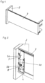
Fig. 1 zeigt ein Möbel 18 aus einem Möbelkorpus 19 und einem über eine Ausziehführung 20 relativ zum Möbelkorpus 19 bewegbaren Möbelteil in Form einer Schublade 15. Diese Schublade 15 besteht im Wesentlichen aus einem Schubladenboden, einer Schubladenrückwand 17, zwei die Seitenwände der Schublade bildende Zargen 3 sowie aus der Frontblende 2. - In
Fig. 2 sind die fluchtend zueinander und übereinander an der Frontblende 2 angeordneten Teile 5a und 5b des Verbindungselementes 5 vor dem Verbinden der Schubladenzarge 3 gezeigt.Fig. 3 zeigt eine aufgebrochene Ansicht zurFig. 2 , wobei die wesentlichen Teile des Möbelbeschlages 1 (zweiteiliges Verbindungselement 5 und Befestigungsvorrichtung 4) ersichtlich sind. - In
Fig. 4 ist die Frontblende 2 an der Schubladenzarge 3 befestigt. Dazu passend ist inFig. 5 gezeigt, wie das erste Teil 5a des Verbindungselementes 5 über dessen Rastelement 7 und das zweite Teil 5b des Verbindungselementes 5 über dessen Rastelement 8 an entsprechenden Einrastnuten 12 an einer Stellplatte 4a der Befestigungsvorrichtung 4 eingehängt sind. - In
Fig. 6 sind auf der rechten Seite die Teile 5a und 5b des Verbindungselementes 5 gezeigt, die jeweils zwei Montagelemente 6 in Form von Dübeln aufweisen. Diese sind in diesem Fall jeweils über ein in die Dübel eingreifendes Spreizteil 23 verbreiterbar, sodass eine Befestigung in einer entsprechenden Bohrung der Frontblende 2 ermöglicht wird. Natürlich soll auch nicht ausgeschlossen werden, dass die Anbringung in Form von Inserterdübeln erfolgt, wie sie beispielsweise aus derEP 0 698 357 A1 bekannt sind. Auch andere Anbringungsarten, wie Einschrauben der einzelnen Montageelemente 6 sollen nicht ausgeschlossen werden. - Im linken Bereich der
Fig. 6 ist die Befestigungsvorrichtung 4 gezeigt, welche im Wesentlichen aus zwei Rahmenplatten 4b und 4c und einer mittleren, gegenüber den Rahmenplatten 4b und 4c verstellbaren Stellplatte 4a besteht. Diese Stellplatte 4a ist gegenüber den Rahmenplatten 4b und 4c durch die Stellelemente 13 und 14 in Höhenrichtung H und in Seitenrichtung SR verstellbar. An der Stellplatte 4a ist auch das verschwenkbare Verriegelungselement 21 angeordnet, das in Montagelage des Verbindungselementes 5 an der Befestigungsvorrichtung 4 das Rastelement 8 im Bereich der Einrastnut 12 arretiert. Durch Verschwenken des Verriegelungselementes 21 in Uhrzeigerrichtung wird die Verriegelungsnase 22 nach links bewegt, sodass durch Anheben der Frontblende die Rastelemente 8 (und 7) nach oben von der Befestigungsvorrichtung 4 gelöst werden können. Um ein Einhängen der gesamten Frontblende 2 über die Teile 5a und 5b des Verbindungselementes vor dem definitiven Arretieren an der Befestigungsvorrichtung 4 zu ermöglichen, ist die Einhängenut 24 an der Stellplatte 4a vorgesehen. - In
Fig. 7 ist in Schnitt A-A die im Querschnitt U-förmige Ausbildung des Verbindungselementes 5 dargestellt, wobei in dem durch die Verbiegung der Laschen 10 verstärkten Quersteg 9 das Montageelement 6 über den Spreizteil 23 angebracht ist. In Schnitt B-B sind die im Wesentlichen parallel zueinander ausgebildeten relativ langen Laschen 10 dargestellt, die mit dem Quersteg 9 das einstückige metallische Basiselement eines jeden Verbindungselementes 5 bilden. Im querstegfernen Bereich verbindet ein Stift 11 die beiden Laschen 10, wobei dieser Stift 11 gleichzeitig als erstes Rastelement 7 und zweites Rastelement 8 ausgebildet ist. - In
Fig. 8 ist nochmals die im Querschnitt U-förmige Ausbildung der Teile 5a und 5b des Verbindungselementes 5 erkennbar. Weiters sind auch die Montageelemente 6 und die Spreizteile 23 sowie die Rastelemente 7 und 8 dargestellt. Natürlich soll nicht ausgeschlossen sein, dass pro Teil 5a oder 5b des Verbindungselementes 5 mehr als zwei Montageelemente 6 ausgebildet sind. Am einfachsten für die Anbringung und auch für das Aufbringen einer gleichmäßigen Einpresskraft beim Anbringen des Verbindungselementes 5 an der Frontblende 2 ist allerdings die Ausführung mit genau zwei Montageelementen 6 pro Teil 5a oder 5b des Verbindungselementes 5.
Claims (13)
- Möbelbeschlag (1) zum Anbringen einer Frontblende (2) an einer Schubladenzarge (3), mit:- einer der Schubladenzarge (3) zugeordneten Befestigungsvorrichtung (4) für die Frontblende (2) und- einem an der Frontblende (2) montierbaren Verbindungselement (5), welches Montageelemente (6), insbesondere Dübel, zum Befestigen an der Frontblende (2) aufweist,wobei das Verbindungselement (5) lösbar, und insbesondere lageverstellbar, an der Befestigungsvorrichtung (4) befestigbar ist und einen ersten Teil (5a) und einen zweiten, in Montagelage zum ersten Teil (5a) beabstandeten, Teil (5b) aufweist, wobei der erste Teil (5a) des Verbindungselements (5) über zumindest zwei Montageelemente (6) mit der Frontblende (2) verbindbar ist und der zweite Teil (5b) des Verbindungselements (5) über zumindest zwei weitere Montageelemente (6) mit der Frontblende (2) verbindbar ist, wobei das Verbindungselement (5) zumindest zwei Rastelemente (7, 8) aufweist und der erste Teil (5a) des Verbindungselements (5) das erste Rastelement (7) und der zweite Teil (5b) des Verbindungselements (5) das zweite Rastelement (8) aufweist, dadurch gekennzeichnet, dass über die Rastelemente (7, 8) das Verbindungselement (5) an der Befestigungsvorrichtung (4) einhängbar ist.
- Möbelbeschlag nach Anspruch 1, dadurch gekennzeichnet, dass die beiden Teile (5a, 5b) des Verbindungselements (5) im Querschnitt U-förmig ausgebildet sind und zwei, zueinander im Wesentlichen parallele, über einen Quersteg (9) miteinander verbundene Laschen (10) aufweist.
- Möbelbeschlag nach Anspruch 2, dadurch gekennzeichnet, dass die zumindest zwei Montageelemente (6) am Quersteg (9) des jeweiligen Teils (5a, 5b) des Verbindungselements (5) befestigt sind und von der laschenabgewandten Seite des Querstegs (9) des jeweiligen Teils (5a, 5b) des Verbindungselements (5) abstehen.
- Möbelbeschlag nach Anspruch 2 oder 3, dadurch gekennzeichnet, dass die Laschen (10) im querstegfernen Bereich durch einen, vorzugsweise metallischen, Stift (11) verbunden sind, der das Rastelement (7, 8) des jeweiligen Teils (5a, 5b) des Verbindungselements (5) bildet, wobei über diesen Stift (11) der jeweilige Teil (5a, 5b) des Verbindungselements (5) an jeweils einer Einrastnut (12) der Befestigungsvorrichtung (4) einhängbar ist.
- Möbelbeschlag nach einem der Ansprüche 1 bis 4, dadurch gekennzeichnet, dass der erste Teil (5a) und der zweite Teil (5b) des Verbindungselements (5) im Wesentlichen identisch ausgebildet sind.
- Möbelbeschlag nach einem der Ansprüche 1 bis 5, dadurch gekennzeichnet, dass der erste Teil (5a) und der zweite Teil (5b) des Verbindungselements (5) in Montagelage an der Frontblende (2) zueinander eine feste, unverstellbare Lagebeziehung aufweisen.
- Möbelbeschlag nach einem der Ansprüche 1 bis 6, dadurch gekennzeichnet, dass die Befestigungsvorrichtung (4) zumindest zwei an einer Stellplatte (4a) der Befestigungsvorrichtung (4) angreifende Stellelemente (13, 14) aufweist, über die das Verbindungselement (5) samt Frontblende (2) in an der Befestigungsvorrichtung (4) montiertem Zustand in Höhenrichtung (HR) und Seitenrichtung (SR) gegenüber der Befestigungsvorrichtung (4) lageverstellbar ist.
- Möbelbeschlag nach Anspruch 7, dadurch gekennzeichnet, dass das Verbindungselement (5) über die Rastelemente (7, 8) an den in der Stellplatte (4a) ausgebildeten Einrastnuten (12), vorzugsweise durch ein Verriegelungselement (21) verriegelbar und lösbar, einhängbar ist.
- Möbelbeschlag nach einem der Ansprüche 1 bis 8, dadurch gekennzeichnet, dass die Befestigungsvorrichtung (4) eine einstückige Stellplatte (4a) aufweist.
- Möbelbeschlag nach Anspruch 9, dadurch gekennzeichnet, dass an der Stellplatte (4a) das erste Teil (5a) und das zweite Teil (5b) des Verbindungselements (5) befestigbar sind.
- Schublade (15) mit einem Schubladenboden (16), einer Schubladenrückwand (17), zwei die Schubladenseitenwände bildende Schubladenzargen (3) und einer Frontblende (2), wobei jede der beiden Schubladenzargen (3) mit der Frontblende (2) durch einen Möbelbeschlag (1) nach einem der Ansprüche 1 bis 10 verbunden ist.
- Möbel (18) mit einem Möbelkorpus (19) und einem gegenüber dem Möbelkorpus (19) relativ bewegbaren Möbelteil in Form einer Schublade (15) nach Anspruch 11.
- Möbelbeschlag (1) zum Anbringen einer Frontblende (2) an einer Schubladenzarge (3), mit:- einer der Schubladenzarge (3) zugeordneten Befestigungsvorrichtung (4) für die Frontblende (2) und- einem an der Frontblende (2) montierbaren Verbindungselement (5), welches Montageelemente (6), insbesondere Dübel, zum Befestigen an der Frontblende (2) aufweist,wobei das Verbindungselement (5) lösbar, und insbesondere lageverstellbar, an der Befestigungsvorrichtung (4) befestigbar ist und einen ersten Teil (5a) und einen zweiten, in Montagelage zum ersten Teil (5a) beabstandeten, Teil (5b) aufweist, wobei der erste Teil (5a) des Verbindungselements (5) über zumindest zwei Montageelemente (6) mit der Frontblende (2) verbindbar ist und der zweite Teil (5b) des Verbindungselements (5) über zumindest zwei weitere Montageelemente (6) mit der Frontblende (2) verbindbar ist, wobei das Verbindungselement (5) zumindest zwei Rastelemente (7, 8) aufweist, über die das Verbindungselement (5) an der Befestigungsvorrichtung (4) befestigbar, vorzugsweise einhängbar, ist, wobei der erste Teil (5a) des Verbindungselements (5) das erste Rastelement (7) und der zweite Teil (5b) des Verbindungselements (5) das zweite Rastelement (8) aufweist, dadurch gekennzeichnet, dass die beiden Teile (5a, 5b) des Verbindungselements (5) im Querschnitt U-förmig ausgebildet sind und zwei, zueinander im Wesentlichen parallele, über einen Quersteg (9) miteinander verbundene Laschen (10) aufweist, wobei der Quersteg (9) durch eine Verbiegung der Laschen (10) verstärkt ist, wobei die Laschen (10) mit dem Quersteg (9) ein einstückiges metallisches Basiselement eines jeden Verbindungselementes (5) bilden, wobei im querstegfernen Bereich ein Stift (11) die beiden Laschen (10) verbindet und der Stift (11) des ersten Teils (5a) das erste Rastelement (7) und der Stift (11) des zweiten Teils (5b) das zweite Rastelement (8) bildet.
Applications Claiming Priority (2)
| Application Number | Priority Date | Filing Date | Title |
|---|---|---|---|
| ATA1938/2010A AT510781B1 (de) | 2010-11-23 | 2010-11-23 | Möbelbeschlag zur frontblendenbefestigung |
| PCT/AT2011/000467 WO2012068602A1 (de) | 2010-11-23 | 2011-11-17 | Möbelbeschlag zur frontblendenbefestiqung |
Publications (3)
| Publication Number | Publication Date |
|---|---|
| EP2642893A1 EP2642893A1 (de) | 2013-10-02 |
| EP2642893B1 EP2642893B1 (de) | 2015-03-11 |
| EP2642893B2 true EP2642893B2 (de) | 2024-11-06 |
Family
ID=45372169
Family Applications (1)
| Application Number | Title | Priority Date | Filing Date |
|---|---|---|---|
| EP11799064.8A Active EP2642893B2 (de) | 2010-11-23 | 2011-11-17 | Möbelbeschlag zur frontblendenbefestigung |
Country Status (8)
| Country | Link |
|---|---|
| US (1) | US8801123B2 (de) |
| EP (1) | EP2642893B2 (de) |
| JP (1) | JP5878547B2 (de) |
| CN (2) | CN104398027B (de) |
| AT (1) | AT510781B1 (de) |
| ES (1) | ES2538829T5 (de) |
| MY (1) | MY164296A (de) |
| WO (1) | WO2012068602A1 (de) |
Families Citing this family (17)
| Publication number | Priority date | Publication date | Assignee | Title |
|---|---|---|---|---|
| AT510779B1 (de) * | 2010-11-23 | 2014-09-15 | Blum Gmbh Julius | Möbelbeschlag zur frontblendenbefestigung |
| AT512022A1 (de) * | 2011-09-23 | 2013-04-15 | Blum Gmbh Julius | Möbel |
| DE202012102289U1 (de) * | 2012-06-21 | 2012-07-13 | Anton Schneider Gmbh & Co Kg | Seiten- und höhenverstellbarer Frontblendenbeschlag |
| DE202013011421U1 (de) * | 2013-12-20 | 2015-03-23 | Grass Gmbh | Schubladenfrontanbindungselnheit |
| DE102014011090A1 (de) * | 2014-07-30 | 2016-02-04 | Erwin Krüger | Befestigungsbeschlag für eine Blende an einer offenen Stirnseite einer Schublade |
| CN104207506B (zh) * | 2014-09-12 | 2016-08-24 | 伍志勇 | 家具抽屉前面板的拆装结构 |
| AT516838B1 (de) * | 2015-03-13 | 2016-09-15 | Blum Gmbh Julius | Befestigungsvorrichtung zum lösbaren Befestigen einer Frontblende an einer Schublade |
| EP3288420B1 (de) * | 2015-04-30 | 2020-09-16 | Arturo Salice S.p.A. | Zusammensetzbare schublade für möbel und verfahren zum zusammensetzen der schublade |
| CN107581807B (zh) * | 2016-07-07 | 2020-03-27 | 川湖科技股份有限公司 | 安装机构 |
| AT520765B1 (de) * | 2017-12-21 | 2023-03-15 | Blum Gmbh Julius | Schubladenseitenwand mit einem Abdeckprofil |
| AT520913A1 (de) * | 2018-02-01 | 2019-08-15 | Blum Gmbh Julius | Möbelbeschlag |
| DE102018124167A1 (de) * | 2018-10-01 | 2020-04-02 | Paul Hettich Gmbh & Co. Kg | Befestigungsvorrichtung zum Befestigen einer Blende eines Schubkastens an einer Zarge |
| AT521512B1 (de) | 2018-10-05 | 2020-02-15 | Blum Gmbh Julius | Befestigungsvorrichtung zum lösbaren Befestigen einer Frontblende an einer Schublade |
| US11511560B2 (en) * | 2018-10-29 | 2022-11-29 | Konnectronix, Inc. | Fine tip stylus nd pen with aperture for coaxial, retraction and placement |
| TWI698199B (zh) | 2019-05-15 | 2020-07-11 | 川湖科技股份有限公司 | 抽屜及其傢俱配件 |
| CN116447206B (zh) * | 2023-05-31 | 2026-02-17 | 广东合固五金精密制造有限公司 | 一种面板前连接组合装置 |
| DE102024207145A1 (de) * | 2024-07-30 | 2026-02-05 | Anton Schneider Gmbh & Co Kg | Frontblendenbeschlag |
Citations (2)
| Publication number | Priority date | Publication date | Assignee | Title |
|---|---|---|---|---|
| EP1393653A1 (de) † | 2002-08-30 | 2004-03-03 | Paul Hettich Gmbh & Co. | Mehrteilige Seitenzarge für einen Schubkasten |
| EP1470768A1 (de) † | 2003-04-16 | 2004-10-27 | Paul Hettich GmbH & Co. KG | Sockelschubkasten |
Family Cites Families (23)
| Publication number | Priority date | Publication date | Assignee | Title |
|---|---|---|---|---|
| AT399086B (de) * | 1981-01-29 | 1995-03-27 | Grass Alfred Metallwaren | Verstellvorrichtung für schubladenblenden, insbesondere für küchenmöbelauszüge |
| AT391406B (de) * | 1985-06-25 | 1990-10-10 | Blum Gmbh Julius | Frontblendenhalterung fuer schubladen |
| AT391987B (de) * | 1987-02-04 | 1990-12-27 | Blum Gmbh Julius | Befestigungsvorrichtung fuer einstellbare frontblenden von schubladen |
| DE3801195A1 (de) * | 1988-01-18 | 1989-07-27 | Hagenhenrich Gmbh & Co Kg | Anordnung zum verbinden von schubkastenseitenzarge und -frontblende |
| DE3931155A1 (de) * | 1989-09-19 | 1991-03-28 | Lautenschlaeger Kg Karl | Befestigungsanordnung fuer schubladen-frontblenden |
| AT402596B (de) | 1994-08-26 | 1997-06-25 | Blum Gmbh Julius | Möbelbeschlag, insbesondere verbindungsbeschlag möbelbeschlag, insbesondere verbindungsbeschlag |
| AT404664B (de) * | 1995-03-20 | 1999-01-25 | Blum Gmbh Julius | Vorrichtung zur befestigung der frontblende einer schublade an schubladenzargen |
| AT404666B (de) * | 1995-10-30 | 1999-01-25 | Blum Gmbh Julius | Schublade |
| DE19944642A1 (de) * | 1999-09-17 | 2001-03-22 | Hettich Paul Gmbh & Co | Befestigungsvorrichtung |
| DE19944639A1 (de) * | 1999-09-17 | 2001-03-22 | Hettich Paul Gmbh & Co | Befestigungsanordnung |
| CN2424677Y (zh) * | 2000-05-12 | 2001-03-28 | 潘建芳 | 改进的抽屉面板连接器 |
| DE10025951A1 (de) * | 2000-05-26 | 2001-11-29 | Hettich Paul Gmbh & Co | Befestigungsanordnung |
| MY135151A (en) * | 2002-05-17 | 2008-02-29 | Harn Marketing Sdn Bhd | Drawer fitting arrangement |
| AT6773U1 (de) * | 2003-05-22 | 2004-04-26 | Blum Gmbh Julius | Vorrichtung zur befestigung einer frontblende an einer schublade |
| AT503418B1 (de) * | 2006-03-28 | 2007-10-15 | Blum Gmbh Julius | Schublade mit wenigstens einer hölzernen schubladenseitenwand |
| AT503672B1 (de) * | 2006-05-26 | 2008-12-15 | Blum Gmbh Julius | Schublade mit aufsatzzargen |
| MY140411A (en) * | 2006-07-14 | 2009-12-31 | Harn Marketing Sdn Bhd | Drawer fitting |
| DE202007001783U1 (de) * | 2006-09-08 | 2008-01-10 | Paul Hettich Gmbh & Co. Kg | Verbindungseinrichtung an einem Schubkasten |
| DE202007001780U1 (de) * | 2006-09-08 | 2008-01-10 | Paul Hettich Gmbh & Co. Kg | Schubkasten |
| AT505432B1 (de) * | 2007-07-11 | 2012-08-15 | Blum Gmbh Julius | Schubladenzarge mit einer befestigungseinrichtung für eine frontblende |
| CN101181116B (zh) * | 2007-11-29 | 2011-03-16 | 罗志明 | 抽屉前面板与抽屉侧面板的连接装置 |
| AT509411B1 (de) | 2010-02-03 | 2012-05-15 | Blum Gmbh Julius | Schubladenzarge |
| AT510779B1 (de) * | 2010-11-23 | 2014-09-15 | Blum Gmbh Julius | Möbelbeschlag zur frontblendenbefestigung |
-
2010
- 2010-11-23 AT ATA1938/2010A patent/AT510781B1/de active
-
2011
- 2011-11-17 JP JP2013539090A patent/JP5878547B2/ja active Active
- 2011-11-17 WO PCT/AT2011/000467 patent/WO2012068602A1/de not_active Ceased
- 2011-11-17 CN CN201410699646.3A patent/CN104398027B/zh active Active
- 2011-11-17 EP EP11799064.8A patent/EP2642893B2/de active Active
- 2011-11-17 CN CN201180056166.XA patent/CN103220941B/zh active Active
- 2011-11-17 ES ES11799064T patent/ES2538829T5/es active Active
- 2011-11-17 MY MYPI2013001738A patent/MY164296A/en unknown
-
2013
- 2013-05-15 US US13/894,853 patent/US8801123B2/en active Active
Patent Citations (2)
| Publication number | Priority date | Publication date | Assignee | Title |
|---|---|---|---|---|
| EP1393653A1 (de) † | 2002-08-30 | 2004-03-03 | Paul Hettich Gmbh & Co. | Mehrteilige Seitenzarge für einen Schubkasten |
| EP1470768A1 (de) † | 2003-04-16 | 2004-10-27 | Paul Hettich GmbH & Co. KG | Sockelschubkasten |
Also Published As
| Publication number | Publication date |
|---|---|
| WO2012068602A1 (de) | 2012-05-31 |
| JP2014500075A (ja) | 2014-01-09 |
| CN103220941B (zh) | 2015-06-10 |
| CN104398027A (zh) | 2015-03-11 |
| AT510781B1 (de) | 2014-08-15 |
| US8801123B2 (en) | 2014-08-12 |
| CN103220941A (zh) | 2013-07-24 |
| EP2642893A1 (de) | 2013-10-02 |
| AT510781A1 (de) | 2012-06-15 |
| ES2538829T3 (es) | 2015-06-24 |
| MY164296A (en) | 2017-12-15 |
| ES2538829T5 (en) | 2025-03-18 |
| EP2642893B1 (de) | 2015-03-11 |
| CN104398027B (zh) | 2017-04-12 |
| US20130249370A1 (en) | 2013-09-26 |
| JP5878547B2 (ja) | 2016-03-08 |
Similar Documents
| Publication | Publication Date | Title |
|---|---|---|
| EP2642893B1 (de) | Möbelbeschlag zur frontblendenbefestigung | |
| EP2642892B1 (de) | Möbelbeschlag zur frontblendenbefestigung | |
| EP2531065B1 (de) | Schubladenzarge | |
| EP3496571B1 (de) | Zarge für einen schubkasten | |
| DE102008019421A1 (de) | Beschlagaufbau und Verfahren zur höhenrichtigen Montage einer Dekorplatte an einer Tür eines Haushaltsgeräts | |
| EP2389836B1 (de) | Verkaufsregal | |
| EP1614369B1 (de) | Schubladenzarge | |
| DE19510119B4 (de) | Schnellmontage-Befestigungsbeschlag für Schubladen-Frontblenden | |
| DE8809236U1 (de) | Tragvorrichtung für eine Wand- oder Deckenverkleidung | |
| DE102011112074A1 (de) | Möbeleinheit | |
| EP2357367A1 (de) | Montagesysteme für Platten und Rohre | |
| EP3745919B1 (de) | Anordnung | |
| EP2840933B1 (de) | Schubladenrückwand | |
| DE202015104529U1 (de) | Pflanzenkastenhalter | |
| DE102007009667B4 (de) | Profilkonstruktion | |
| EP4424210B1 (de) | Regaleinschub | |
| EP3666121A1 (de) | Schubladenfront-verbindungsvorrichtung und schublade | |
| DE102014101284B3 (de) | Zargenanordnung sowie Befestigungsplatte | |
| DE202013004939U1 (de) | Vorrichtung zur Positionierung und Fixierung eines beweglichen Möbelteils | |
| DE102023122941A1 (de) | Freizeitfahrzeug, Schiebetür und Federelement für Schiebetüren von Freizeitfahrzeugen | |
| AT379061B (de) | Schubkastenauszug | |
| DE102014217635B4 (de) | Haushaltsgerät | |
| DE19622735A1 (de) | Kupplungsanordnung | |
| DE29802821U1 (de) | Warengestell mit höhenverstellbarem Fachboden |
Legal Events
| Date | Code | Title | Description |
|---|---|---|---|
| PUAI | Public reference made under article 153(3) epc to a published international application that has entered the european phase |
Free format text: ORIGINAL CODE: 0009012 |
|
| 17P | Request for examination filed |
Effective date: 20130424 |
|
| AK | Designated contracting states |
Kind code of ref document: A1 Designated state(s): AL AT BE BG CH CY CZ DE DK EE ES FI FR GB GR HR HU IE IS IT LI LT LU LV MC MK MT NL NO PL PT RO RS SE SI SK SM TR |
|
| DAX | Request for extension of the european patent (deleted) | ||
| GRAP | Despatch of communication of intention to grant a patent |
Free format text: ORIGINAL CODE: EPIDOSNIGR1 |
|
| INTG | Intention to grant announced |
Effective date: 20141205 |
|
| GRAS | Grant fee paid |
Free format text: ORIGINAL CODE: EPIDOSNIGR3 |
|
| GRAA | (expected) grant |
Free format text: ORIGINAL CODE: 0009210 |
|
| AK | Designated contracting states |
Kind code of ref document: B1 Designated state(s): AL AT BE BG CH CY CZ DE DK EE ES FI FR GB GR HR HU IE IS IT LI LT LU LV MC MK MT NL NO PL PT RO RS SE SI SK SM TR |
|
| REG | Reference to a national code |
Ref country code: GB Ref legal event code: FG4D Free format text: NOT ENGLISH |
|
| REG | Reference to a national code |
Ref country code: CH Ref legal event code: EP |
|
| REG | Reference to a national code |
Ref country code: IE Ref legal event code: FG4D Free format text: LANGUAGE OF EP DOCUMENT: GERMAN |
|
| REG | Reference to a national code |
Ref country code: AT Ref legal event code: REF Ref document number: 714839 Country of ref document: AT Kind code of ref document: T Effective date: 20150415 |
|
| REG | Reference to a national code |
Ref country code: DE Ref legal event code: R096 Ref document number: 502011006234 Country of ref document: DE Effective date: 20150423 |
|
| REG | Reference to a national code |
Ref country code: ES Ref legal event code: FG2A Ref document number: 2538829 Country of ref document: ES Kind code of ref document: T3 Effective date: 20150624 |
|
| REG | Reference to a national code |
Ref country code: NL Ref legal event code: VDEP Effective date: 20150311 |
|
| REG | Reference to a national code |
Ref country code: NL Ref legal event code: VDEP Effective date: 20150311 |
|
| PG25 | Lapsed in a contracting state [announced via postgrant information from national office to epo] |
Ref country code: FI Free format text: LAPSE BECAUSE OF FAILURE TO SUBMIT A TRANSLATION OF THE DESCRIPTION OR TO PAY THE FEE WITHIN THE PRESCRIBED TIME-LIMIT Effective date: 20150311 Ref country code: LT Free format text: LAPSE BECAUSE OF FAILURE TO SUBMIT A TRANSLATION OF THE DESCRIPTION OR TO PAY THE FEE WITHIN THE PRESCRIBED TIME-LIMIT Effective date: 20150311 Ref country code: SE Free format text: LAPSE BECAUSE OF FAILURE TO SUBMIT A TRANSLATION OF THE DESCRIPTION OR TO PAY THE FEE WITHIN THE PRESCRIBED TIME-LIMIT Effective date: 20150311 Ref country code: NO Free format text: LAPSE BECAUSE OF FAILURE TO SUBMIT A TRANSLATION OF THE DESCRIPTION OR TO PAY THE FEE WITHIN THE PRESCRIBED TIME-LIMIT Effective date: 20150611 Ref country code: HR Free format text: LAPSE BECAUSE OF FAILURE TO SUBMIT A TRANSLATION OF THE DESCRIPTION OR TO PAY THE FEE WITHIN THE PRESCRIBED TIME-LIMIT Effective date: 20150311 |
|
| REG | Reference to a national code |
Ref country code: LT Ref legal event code: MG4D |
|
| PG25 | Lapsed in a contracting state [announced via postgrant information from national office to epo] |
Ref country code: LV Free format text: LAPSE BECAUSE OF FAILURE TO SUBMIT A TRANSLATION OF THE DESCRIPTION OR TO PAY THE FEE WITHIN THE PRESCRIBED TIME-LIMIT Effective date: 20150311 Ref country code: GR Free format text: LAPSE BECAUSE OF FAILURE TO SUBMIT A TRANSLATION OF THE DESCRIPTION OR TO PAY THE FEE WITHIN THE PRESCRIBED TIME-LIMIT Effective date: 20150612 Ref country code: RS Free format text: LAPSE BECAUSE OF FAILURE TO SUBMIT A TRANSLATION OF THE DESCRIPTION OR TO PAY THE FEE WITHIN THE PRESCRIBED TIME-LIMIT Effective date: 20150311 |
|
| PG25 | Lapsed in a contracting state [announced via postgrant information from national office to epo] |
Ref country code: NL Free format text: LAPSE BECAUSE OF FAILURE TO SUBMIT A TRANSLATION OF THE DESCRIPTION OR TO PAY THE FEE WITHIN THE PRESCRIBED TIME-LIMIT Effective date: 20150311 |
|
| PG25 | Lapsed in a contracting state [announced via postgrant information from national office to epo] |
Ref country code: RO Free format text: LAPSE BECAUSE OF FAILURE TO SUBMIT A TRANSLATION OF THE DESCRIPTION OR TO PAY THE FEE WITHIN THE PRESCRIBED TIME-LIMIT Effective date: 20150311 Ref country code: EE Free format text: LAPSE BECAUSE OF FAILURE TO SUBMIT A TRANSLATION OF THE DESCRIPTION OR TO PAY THE FEE WITHIN THE PRESCRIBED TIME-LIMIT Effective date: 20150311 Ref country code: CZ Free format text: LAPSE BECAUSE OF FAILURE TO SUBMIT A TRANSLATION OF THE DESCRIPTION OR TO PAY THE FEE WITHIN THE PRESCRIBED TIME-LIMIT Effective date: 20150311 Ref country code: SK Free format text: LAPSE BECAUSE OF FAILURE TO SUBMIT A TRANSLATION OF THE DESCRIPTION OR TO PAY THE FEE WITHIN THE PRESCRIBED TIME-LIMIT Effective date: 20150311 Ref country code: PT Free format text: LAPSE BECAUSE OF FAILURE TO SUBMIT A TRANSLATION OF THE DESCRIPTION OR TO PAY THE FEE WITHIN THE PRESCRIBED TIME-LIMIT Effective date: 20150713 |
|
| REG | Reference to a national code |
Ref country code: DE Ref legal event code: R026 Ref document number: 502011006234 Country of ref document: DE |
|
| PLBI | Opposition filed |
Free format text: ORIGINAL CODE: 0009260 |
|
| PG25 | Lapsed in a contracting state [announced via postgrant information from national office to epo] |
Ref country code: IS Free format text: LAPSE BECAUSE OF FAILURE TO SUBMIT A TRANSLATION OF THE DESCRIPTION OR TO PAY THE FEE WITHIN THE PRESCRIBED TIME-LIMIT Effective date: 20150711 Ref country code: PL Free format text: LAPSE BECAUSE OF FAILURE TO SUBMIT A TRANSLATION OF THE DESCRIPTION OR TO PAY THE FEE WITHIN THE PRESCRIBED TIME-LIMIT Effective date: 20150311 |
|
| PLBI | Opposition filed |
Free format text: ORIGINAL CODE: 0009260 |
|
| 26 | Opposition filed |
Opponent name: GRASS GMBH Effective date: 20151120 |
|
| PLAX | Notice of opposition and request to file observation + time limit sent |
Free format text: ORIGINAL CODE: EPIDOSNOBS2 |
|
| 26 | Opposition filed |
Opponent name: PAUL HETTICH GMBH & CO. KG Effective date: 20151209 |
|
| PG25 | Lapsed in a contracting state [announced via postgrant information from national office to epo] |
Ref country code: DK Free format text: LAPSE BECAUSE OF FAILURE TO SUBMIT A TRANSLATION OF THE DESCRIPTION OR TO PAY THE FEE WITHIN THE PRESCRIBED TIME-LIMIT Effective date: 20150311 |
|
| PG25 | Lapsed in a contracting state [announced via postgrant information from national office to epo] |
Ref country code: SI Free format text: LAPSE BECAUSE OF FAILURE TO SUBMIT A TRANSLATION OF THE DESCRIPTION OR TO PAY THE FEE WITHIN THE PRESCRIBED TIME-LIMIT Effective date: 20150311 |
|
| PLAF | Information modified related to communication of a notice of opposition and request to file observations + time limit |
Free format text: ORIGINAL CODE: EPIDOSCOBS2 |
|
| PG25 | Lapsed in a contracting state [announced via postgrant information from national office to epo] |
Ref country code: LU Free format text: LAPSE BECAUSE OF FAILURE TO SUBMIT A TRANSLATION OF THE DESCRIPTION OR TO PAY THE FEE WITHIN THE PRESCRIBED TIME-LIMIT Effective date: 20151117 Ref country code: MC Free format text: LAPSE BECAUSE OF FAILURE TO SUBMIT A TRANSLATION OF THE DESCRIPTION OR TO PAY THE FEE WITHIN THE PRESCRIBED TIME-LIMIT Effective date: 20150311 |
|
| REG | Reference to a national code |
Ref country code: CH Ref legal event code: PL |
|
| GBPC | Gb: european patent ceased through non-payment of renewal fee |
Effective date: 20151117 |
|
| PG25 | Lapsed in a contracting state [announced via postgrant information from national office to epo] |
Ref country code: LI Free format text: LAPSE BECAUSE OF NON-PAYMENT OF DUE FEES Effective date: 20151130 Ref country code: CH Free format text: LAPSE BECAUSE OF NON-PAYMENT OF DUE FEES Effective date: 20151130 |
|
| PLBB | Reply of patent proprietor to notice(s) of opposition received |
Free format text: ORIGINAL CODE: EPIDOSNOBS3 |
|
| REG | Reference to a national code |
Ref country code: IE Ref legal event code: MM4A |
|
| REG | Reference to a national code |
Ref country code: FR Ref legal event code: ST Effective date: 20160729 |
|
| PG25 | Lapsed in a contracting state [announced via postgrant information from national office to epo] |
Ref country code: GB Free format text: LAPSE BECAUSE OF NON-PAYMENT OF DUE FEES Effective date: 20151117 Ref country code: IE Free format text: LAPSE BECAUSE OF NON-PAYMENT OF DUE FEES Effective date: 20151117 |
|
| PG25 | Lapsed in a contracting state [announced via postgrant information from national office to epo] |
Ref country code: FR Free format text: LAPSE BECAUSE OF NON-PAYMENT OF DUE FEES Effective date: 20151130 |
|
| PLAB | Opposition data, opponent's data or that of the opponent's representative modified |
Free format text: ORIGINAL CODE: 0009299OPPO |
|
| R26 | Opposition filed (corrected) |
Opponent name: GRASS GMBH Effective date: 20151120 |
|
| PG25 | Lapsed in a contracting state [announced via postgrant information from national office to epo] |
Ref country code: HU Free format text: LAPSE BECAUSE OF FAILURE TO SUBMIT A TRANSLATION OF THE DESCRIPTION OR TO PAY THE FEE WITHIN THE PRESCRIBED TIME-LIMIT; INVALID AB INITIO Effective date: 20111117 Ref country code: SM Free format text: LAPSE BECAUSE OF FAILURE TO SUBMIT A TRANSLATION OF THE DESCRIPTION OR TO PAY THE FEE WITHIN THE PRESCRIBED TIME-LIMIT Effective date: 20150311 Ref country code: BG Free format text: LAPSE BECAUSE OF FAILURE TO SUBMIT A TRANSLATION OF THE DESCRIPTION OR TO PAY THE FEE WITHIN THE PRESCRIBED TIME-LIMIT Effective date: 20150311 |
|
| PG25 | Lapsed in a contracting state [announced via postgrant information from national office to epo] |
Ref country code: CY Free format text: LAPSE BECAUSE OF FAILURE TO SUBMIT A TRANSLATION OF THE DESCRIPTION OR TO PAY THE FEE WITHIN THE PRESCRIBED TIME-LIMIT Effective date: 20150311 |
|
| PG25 | Lapsed in a contracting state [announced via postgrant information from national office to epo] |
Ref country code: BE Free format text: LAPSE BECAUSE OF NON-PAYMENT OF DUE FEES Effective date: 20151130 |
|
| PG25 | Lapsed in a contracting state [announced via postgrant information from national office to epo] |
Ref country code: MT Free format text: LAPSE BECAUSE OF FAILURE TO SUBMIT A TRANSLATION OF THE DESCRIPTION OR TO PAY THE FEE WITHIN THE PRESCRIBED TIME-LIMIT Effective date: 20150311 |
|
| APAH | Appeal reference modified |
Free format text: ORIGINAL CODE: EPIDOSCREFNO |
|
| APBM | Appeal reference recorded |
Free format text: ORIGINAL CODE: EPIDOSNREFNO |
|
| APBP | Date of receipt of notice of appeal recorded |
Free format text: ORIGINAL CODE: EPIDOSNNOA2O |
|
| APBM | Appeal reference recorded |
Free format text: ORIGINAL CODE: EPIDOSNREFNO |
|
| APBP | Date of receipt of notice of appeal recorded |
Free format text: ORIGINAL CODE: EPIDOSNNOA2O |
|
| PG25 | Lapsed in a contracting state [announced via postgrant information from national office to epo] |
Ref country code: MK Free format text: LAPSE BECAUSE OF FAILURE TO SUBMIT A TRANSLATION OF THE DESCRIPTION OR TO PAY THE FEE WITHIN THE PRESCRIBED TIME-LIMIT Effective date: 20150311 |
|
| APBM | Appeal reference recorded |
Free format text: ORIGINAL CODE: EPIDOSNREFNO |
|
| APBP | Date of receipt of notice of appeal recorded |
Free format text: ORIGINAL CODE: EPIDOSNNOA2O |
|
| APBQ | Date of receipt of statement of grounds of appeal recorded |
Free format text: ORIGINAL CODE: EPIDOSNNOA3O |
|
| APBQ | Date of receipt of statement of grounds of appeal recorded |
Free format text: ORIGINAL CODE: EPIDOSNNOA3O |
|
| PG25 | Lapsed in a contracting state [announced via postgrant information from national office to epo] |
Ref country code: AL Free format text: LAPSE BECAUSE OF FAILURE TO SUBMIT A TRANSLATION OF THE DESCRIPTION OR TO PAY THE FEE WITHIN THE PRESCRIBED TIME-LIMIT Effective date: 20150311 |
|
| APAH | Appeal reference modified |
Free format text: ORIGINAL CODE: EPIDOSCREFNO |
|
| APAH | Appeal reference modified |
Free format text: ORIGINAL CODE: EPIDOSCREFNO |
|
| APBU | Appeal procedure closed |
Free format text: ORIGINAL CODE: EPIDOSNNOA9O |
|
| PLAY | Examination report in opposition despatched + time limit |
Free format text: ORIGINAL CODE: EPIDOSNORE2 |
|
| PLBC | Reply to examination report in opposition received |
Free format text: ORIGINAL CODE: EPIDOSNORE3 |
|
| PLAY | Examination report in opposition despatched + time limit |
Free format text: ORIGINAL CODE: EPIDOSNORE2 |
|
| RIC2 | Information provided on ipc code assigned after grant |
Ipc: A47B 88/95 20170101ALI20230302BHEP Ipc: A47B 88/956 20170101AFI20230302BHEP |
|
| P01 | Opt-out of the competence of the unified patent court (upc) registered |
Effective date: 20230523 |
|
| PLAP | Information related to despatch of examination report in opposition + time limit deleted |
Free format text: ORIGINAL CODE: EPIDOSDORE2 |
|
| PUAH | Patent maintained in amended form |
Free format text: ORIGINAL CODE: 0009272 |
|
| STAA | Information on the status of an ep patent application or granted ep patent |
Free format text: STATUS: PATENT MAINTAINED AS AMENDED |
|
| 27A | Patent maintained in amended form |
Effective date: 20241106 |
|
| AK | Designated contracting states |
Kind code of ref document: B2 Designated state(s): AL AT BE BG CH CY CZ DE DK EE ES FI FR GB GR HR HU IE IS IT LI LT LU LV MC MK MT NL NO PL PT RO RS SE SI SK SM TR |
|
| REG | Reference to a national code |
Ref country code: DE Ref legal event code: R102 Ref document number: 502011006234 Country of ref document: DE |
|
| REG | Reference to a national code |
Ref country code: ES Ref legal event code: DC2A Ref document number: 2538829 Country of ref document: ES Kind code of ref document: T5 Effective date: 20250318 |
|
| PGFP | Annual fee paid to national office [announced via postgrant information from national office to epo] |
Ref country code: DE Payment date: 20251126 Year of fee payment: 15 |
|
| PGFP | Annual fee paid to national office [announced via postgrant information from national office to epo] |
Ref country code: AT Payment date: 20251126 Year of fee payment: 15 |
|
| PGFP | Annual fee paid to national office [announced via postgrant information from national office to epo] |
Ref country code: IT Payment date: 20251121 Year of fee payment: 15 |
|
| PGFP | Annual fee paid to national office [announced via postgrant information from national office to epo] |
Ref country code: TR Payment date: 20251027 Year of fee payment: 15 |
|
| PGFP | Annual fee paid to national office [announced via postgrant information from national office to epo] |
Ref country code: ES Payment date: 20251209 Year of fee payment: 15 |