EP2643112B1 - Procédé de fabrication d'une pièce par couches - Google Patents
Procédé de fabrication d'une pièce par couches Download PDFInfo
- Publication number
- EP2643112B1 EP2643112B1 EP11843009.9A EP11843009A EP2643112B1 EP 2643112 B1 EP2643112 B1 EP 2643112B1 EP 11843009 A EP11843009 A EP 11843009A EP 2643112 B1 EP2643112 B1 EP 2643112B1
- Authority
- EP
- European Patent Office
- Prior art keywords
- powder
- layer
- recess
- depression
- parameter
- Prior art date
- Legal status (The legal status is an assumption and is not a legal conclusion. Google has not performed a legal analysis and makes no representation as to the accuracy of the status listed.)
- Active
Links
Images
Classifications
-
- B—PERFORMING OPERATIONS; TRANSPORTING
- B29—WORKING OF PLASTICS; WORKING OF SUBSTANCES IN A PLASTIC STATE IN GENERAL
- B29C—SHAPING OR JOINING OF PLASTICS; SHAPING OF MATERIAL IN A PLASTIC STATE, NOT OTHERWISE PROVIDED FOR; AFTER-TREATMENT OF THE SHAPED PRODUCTS, e.g. REPAIRING
- B29C64/00—Additive manufacturing, i.e. manufacturing of three-dimensional [3D] objects by additive deposition, additive agglomeration or additive layering, e.g. by 3D printing, stereolithography or selective laser sintering
- B29C64/10—Processes of additive manufacturing
- B29C64/141—Processes of additive manufacturing using only solid materials
- B29C64/153—Processes of additive manufacturing using only solid materials using layers of powder being selectively joined, e.g. by selective laser sintering or melting
-
- B—PERFORMING OPERATIONS; TRANSPORTING
- B05—SPRAYING OR ATOMISING IN GENERAL; APPLYING FLUENT MATERIALS TO SURFACES, IN GENERAL
- B05D—PROCESSES FOR APPLYING FLUENT MATERIALS TO SURFACES, IN GENERAL
- B05D3/00—Pretreatment of surfaces to which liquids or other fluent materials are to be applied; After-treatment of applied coatings, e.g. intermediate treating of an applied coating preparatory to subsequent applications of liquids or other fluent materials
- B05D3/06—Pretreatment of surfaces to which liquids or other fluent materials are to be applied; After-treatment of applied coatings, e.g. intermediate treating of an applied coating preparatory to subsequent applications of liquids or other fluent materials by exposure to radiation
-
- B—PERFORMING OPERATIONS; TRANSPORTING
- B22—CASTING; POWDER METALLURGY
- B22F—WORKING METALLIC POWDER; MANUFACTURE OF ARTICLES FROM METALLIC POWDER; MAKING METALLIC POWDER; APPARATUS OR DEVICES SPECIALLY ADAPTED FOR METALLIC POWDER
- B22F10/00—Additive manufacturing of workpieces or articles from metallic powder
- B22F10/20—Direct sintering or melting
- B22F10/28—Powder bed fusion, e.g. selective laser melting [SLM] or electron beam melting [EBM]
-
- B—PERFORMING OPERATIONS; TRANSPORTING
- B22—CASTING; POWDER METALLURGY
- B22F—WORKING METALLIC POWDER; MANUFACTURE OF ARTICLES FROM METALLIC POWDER; MAKING METALLIC POWDER; APPARATUS OR DEVICES SPECIALLY ADAPTED FOR METALLIC POWDER
- B22F12/00—Apparatus or devices specially adapted for additive manufacturing; Auxiliary means for additive manufacturing; Combinations of additive manufacturing apparatus or devices with other processing apparatus or devices
- B22F12/60—Planarisation devices; Compression devices
- B22F12/67—Blades
-
- B—PERFORMING OPERATIONS; TRANSPORTING
- B22—CASTING; POWDER METALLURGY
- B22F—WORKING METALLIC POWDER; MANUFACTURE OF ARTICLES FROM METALLIC POWDER; MAKING METALLIC POWDER; APPARATUS OR DEVICES SPECIALLY ADAPTED FOR METALLIC POWDER
- B22F12/00—Apparatus or devices specially adapted for additive manufacturing; Auxiliary means for additive manufacturing; Combinations of additive manufacturing apparatus or devices with other processing apparatus or devices
- B22F12/90—Means for process control, e.g. cameras or sensors
-
- Y—GENERAL TAGGING OF NEW TECHNOLOGICAL DEVELOPMENTS; GENERAL TAGGING OF CROSS-SECTIONAL TECHNOLOGIES SPANNING OVER SEVERAL SECTIONS OF THE IPC; TECHNICAL SUBJECTS COVERED BY FORMER USPC CROSS-REFERENCE ART COLLECTIONS [XRACs] AND DIGESTS
- Y02—TECHNOLOGIES OR APPLICATIONS FOR MITIGATION OR ADAPTATION AGAINST CLIMATE CHANGE
- Y02P—CLIMATE CHANGE MITIGATION TECHNOLOGIES IN THE PRODUCTION OR PROCESSING OF GOODS
- Y02P10/00—Technologies related to metal processing
- Y02P10/25—Process efficiency
Definitions
- the present invention provides a method for producing a component in layers.
- Rapid prototyping processes Processes for producing a component in layers are also referred to as generative production processes or rapid prototyping processes.
- components are made from formless or shape-neutral materials. This happens due to chemical or physical processes that are controlled by means of a computer-based data model. Rapid prototyping processes are characterized by the fact that components can be manufactured within a very short time, in particular without having to manufacture complex tools to manufacture the components beforehand.
- US 2002/104973 A1 and DE 41 12 695 A1 devices are also known that can detect at least one parameter, can depressions smooth and can fill a depression.
- a method for producing a component in layers is also known from US Pat EP 731743 B1 known.
- powder layers are sintered using a laser.
- the thermal radiation is recorded.
- the laser power for exposing a respective powder layer is adjusted depending on the thermal radiation detected. This is intended to eliminate defects in previous powder layers.
- the object of the present invention is to provide a method for producing a component in layers, in which the occurrence of the aforementioned chambers is avoided or at least reduced.
- a method for producing a component from powder in layers comprising the following steps: detecting at least one parameter of a depression in a layer of the component formed; Smoothing the recess when the at least one parameter exceeds a predetermined value; and filling the smoothed depression with powder; provided.
- a device for producing a component from powder in layers, comprising: a first device for detecting at least one parameter of a recess in a formed layer of the component; second means for smoothing the recess when the at least one parameter exceeds a predetermined value; and third means for filling the smoothed depression with powder; presented.
- the idea on which the present invention is based consists in detecting and smoothing depressions in a layer of the component formed. This smoothing is such that the depression can then be refilled with powder, that is to say the smoothed depression is wider than the maximum powder size and, if appropriate, freed from overhangs.
- the parameter is chosen so that not every depression is smoothed, but only the depressions that are narrower than the maximum powder grain size or have an overhang, for example, are smoothed. The chambers described in the introduction can thus be avoided efficiently.
- the at least one parameter describes a depth of the depression.
- a depth of the depression is easier to measure than, for example, a width of the depression. This is particularly the case if a laser or electron beam is used to measure the depth of the depression.
- the parameter is determined as a function of a retroreflection of a laser beam or electron beam scanning the depression.
- the reflection can be used to easily infer the depth of the depression using triangulation.
- the parameter is determined as a function of an edge radiation of the back radiation. This makes it easy to measure the angle required for triangulation.
- the depression is smoothed by means of a laser beam or an electron beam.
- the laser or electron beam have two functions: On the one hand he scans the recess for the detection of the at least one parameter. On the other hand, it serves to smooth the recess.
- the smoothing is carried out by melting the depression several times. This gradually smoothes the recess. This results in a controlled process that requires limited energy input.
- an energy input for melting the powder filling the depression is chosen to be greater than an energy input in areas adjacent to the depression. Since the powder layer thickness is greater in the recess than in adjacent areas, a higher energy input may also be necessary here.
- the parameter is recorded simultaneously with the formation of the layer.
- the laser or electron beam has three functions: firstly, the parameter is captured, secondly, the depression is smoothed, and thirdly, the layer is formed. As a result, the process can run very quickly.
- the layer is formed by melting a first powder layer, in particular by means of a laser or electron beam, and / or the powder for filling up the depression is part of a second powder layer covering the first powder layer.
- “melting” also includes “sintering”. According to this configuration, the depression is filled up simultaneously with the formation of the second powder layer, which is efficient.
- the first and / or second powder layer can be applied with a doctor knife.
- the application of the first powder layer, the detection of the at least one parameter, the smoothing are preferred the deepening and filling of the same with powder by applying the second powder layer on the first powder layer is repeated until the finished component is formed.
- First powder layer means the preceding layer
- second powder layer means the following layer.
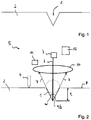
- Figure 1 schematically shows a depression 1.
- the depression 1 is formed in a layer 2 of a component section which is otherwise not shown.
- the Layer 2 is formed in that, in a previous method step, a first powder layer, for example titanium powder, has been applied to a table or a previous layer, and this has subsequently been applied by means of an in Figure 2 shown laser 3 has been melted.
- the depression 1 can, for example, due to an uneven application of the first powder layer by means of the in Figure 2 indicated squeegee 4 have arisen.
- the deepening may be due to a poor quality of the powder of the first powder layer. This can be the case, for example, if the powder has powder grains of very different sizes.
- Figure 2 shows schematically in a side view a device 5 for the layer-by-layer production of a component and the layer 2 with the depression 1 from FIG. 1.
- the device 5 has the laser 3 already mentioned, which generates a laser beam 6.
- the laser beam 6 serves to melt the first powder layer in order to thereby generate the layer 2. Then, or preferably simultaneously with the melting of the first powder layer to produce the layer 2, the surface geometry of the layer 2 formed (which is then still present as a molten bath) is also recorded. In particular, the penetration depth t of the laser beam 6 into the layer 2 or into the scanned component section (the depression 1 can also extend over several layers 2) is recorded.
- the penetration depth t is preferably measured in that the retroreflection 7, that is to say the reflection of the laser beam 6 from the surface 8 of the layer 2 or the depression 1, is detected in one or more sensors 11.
- the edge radiation is preferably detected by the sensors 11.
- the sensors 11 are arranged behind a lens 10 of the laser 3.
- the angle ⁇ can be concluded.
- the angle ⁇ is the angle between two ones in one Top view from Figure 2 diagonally opposite edge rays 7.
- the angle ⁇ / 2 can also be measured, which is the angle between the laser beam 6 and one of the edge rays 7.
- the penetration depth t can in turn be determined on the basis of the angle ⁇ .
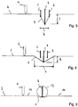
- a control device 12 of the device 5 now determines that the penetration depth t exceeds a predetermined threshold value, then this controls the laser 3 for smoothing the depression 1, as in FIG Figure 3 shown.
- the smoothing is achieved in that the laser beam 6 sweeps several times over the depression 1, as in FIG Figure 3 indicated by the three laser beams 6, thereby melting the material of the recess 1.
- the material is melted until the penetration depth t of the laser beam 6 is reduced. This is done in particular by increasing the width b of the depression 1 due to the flowing material.
- the penetration depth t and possibly the width b of the depression 1 are continuously monitored by the control device 12.
- the smoothing of the depression 1 is repeated until the depth of penetration t falls below a predetermined threshold. Additionally or alternatively, the smoothing can take place depending on the width B.
- the smoothing or multiple melting is preferably repeated until the largest powder grain 13 potentially contained in the powder fits into the depression 1, as in FIG Figure 5 shown.
- further powder is then applied to the existing layer 2 by means of the doctor blade 4 in order to produce a further powder layer thereon.
- One or more powder grains 13 fill out the smoothed depression 1.
- the further powder layer comprising the powder grains 13 is melted by means of the laser beam 6.
- the laser power of the laser 3 can be increased compared to surrounding areas 14 of the further powder layer (not shown), which may be necessary to melt all the powder 13 in the recess 1.
Landscapes
- Engineering & Computer Science (AREA)
- Physics & Mathematics (AREA)
- Chemical & Material Sciences (AREA)
- Materials Engineering (AREA)
- Optics & Photonics (AREA)
- Manufacturing & Machinery (AREA)
- Mechanical Engineering (AREA)
- Plasma & Fusion (AREA)
- Powder Metallurgy (AREA)
Claims (9)
- Procédé de fabrication par couches d'une pièce à base de poudre, comprenant les étapes suivantes :détection d'au moins un paramètre (t) d'un évidement (1) dans une couche formée (2) de la pièce ;lissage de l'évidement (1) si l'au moins un paramètre (t) dépasse une valeur prédéfinie ; etremplissage de l'évidement (1) lissé avec de la poudre (13).
- Procédé selon la revendication 1, caractérisé en ce que l'au moins un paramètre (t) décrit une profondeur de l'évidement (1).
- Procédé selon la revendication 1 ou 2, caractérisé en ce que le paramètre (t) est déterminé en fonction de la réflexion (7) d'un faisceau laser (6) ou d'un faisceau électronique balayant l'évidement (1).
- Procédé selon la revendication 3, caractérisé en ce que le paramètre (t) est déterminé en fonction du rayonnement marginal (7) de la réflexion.
- Procédé selon l'une des revendications précédentes, caractérisé en ce que l'évidement (1) est lissé au moyen d'un faisceau laser (6) ou d'un faisceau électronique.
- Procédé selon l'une des revendications précédentes, caractérisé en ce que le lissage est effectué par fusion multiple de l'évidement (1).
- Procédé selon l'une des revendications précédentes, caractérisé en ce qu'un apport d'énergie servant à la fusion de la poudre (13) remplissant l'évidement (1) est choisi supérieur à un apport d'énergie dans les zones (14) adjacentes à l'évidement (1).
- Procédé selon l'une des revendications précédentes, caractérisé en ce que le paramètre (t) est détecté simultanément avec la formation de la couche (2).
- Procédé selon l'une des revendications précédentes, caractérisé en ce que la couche (2) est formée par fusion d'une première couche de poudre, en particulier au moyen d'un faisceau laser ou électronique (6), et/ou en ce que la poudre (13) servant à remplir l'évidement (1) fait partie d'une seconde couche de poudre recouvrant la première couche de poudre.
Priority Applications (1)
| Application Number | Priority Date | Filing Date | Title |
|---|---|---|---|
| PL11843009T PL2643112T3 (pl) | 2010-11-26 | 2011-11-10 | Sposób warstwowego wytwarzania elementu konstrukcji |
Applications Claiming Priority (3)
| Application Number | Priority Date | Filing Date | Title |
|---|---|---|---|
| DE102010052724 | 2010-11-26 | ||
| DE102011006941A DE102011006941A1 (de) | 2010-11-26 | 2011-04-07 | Verfahren zum schichtweisen Herstellen eines Bauteils sowie Vorrichtung |
| PCT/DE2011/001966 WO2012069037A2 (fr) | 2010-11-26 | 2011-11-10 | Procédé de fabrication d'une pièce par couches et dispositif correspondant |
Publications (2)
| Publication Number | Publication Date |
|---|---|
| EP2643112A2 EP2643112A2 (fr) | 2013-10-02 |
| EP2643112B1 true EP2643112B1 (fr) | 2020-01-01 |
Family
ID=46049870
Family Applications (1)
| Application Number | Title | Priority Date | Filing Date |
|---|---|---|---|
| EP11843009.9A Active EP2643112B1 (fr) | 2010-11-26 | 2011-11-10 | Procédé de fabrication d'une pièce par couches |
Country Status (5)
| Country | Link |
|---|---|
| US (1) | US11077463B2 (fr) |
| EP (1) | EP2643112B1 (fr) |
| DE (1) | DE102011006941A1 (fr) |
| PL (1) | PL2643112T3 (fr) |
| WO (1) | WO2012069037A2 (fr) |
Families Citing this family (9)
| Publication number | Priority date | Publication date | Assignee | Title |
|---|---|---|---|---|
| GB201313841D0 (en) * | 2013-08-02 | 2013-09-18 | Rolls Royce Plc | Method of Manufacturing a Component |
| GB201313840D0 (en) | 2013-08-02 | 2013-09-18 | Rolls Royce Plc | Method of Manufacturing a Component |
| DE102014207001A1 (de) * | 2014-04-11 | 2015-10-15 | MTU Aero Engines AG | Verfahren und Vorrichtung zur Verbesserung der Werkstoffqualität bei generativen Herstellverfahren |
| SE1450569A1 (sv) * | 2014-05-14 | 2015-11-03 | Katarina Gustafsson | En metod och en apparat för geometrisk verifiering vid additiv tillverkning av tredimensionella objekt |
| DE102015000100A1 (de) | 2015-01-14 | 2016-07-14 | Cl Schutzrechtsverwaltungs Gmbh | Verfahren zur Hestellung von dreidimensionalen Bauteilen |
| US10350875B2 (en) | 2015-10-29 | 2019-07-16 | Nike, Inc. | Printing layer in response to substrate contour |
| DE102015224395A1 (de) * | 2015-12-07 | 2017-06-08 | Bayerische Motoren Werke Aktiengesellschaft | Vorrichtung und Verfahren zum Herstellen eines Bauteils in Schichtbauweise, Verwendung einer Erfassungseinrichtung in einem Schichtbauverfahren |
| DE102018101522A1 (de) * | 2018-01-24 | 2019-07-25 | Lunovu Gmbh | Verfahren und Vorrichtung zum Aufbringen einer dreidimensionalen Struktur auf einer Oberfläche eines Werkstücks |
| CN117841365B (zh) * | 2024-03-06 | 2024-05-10 | 云耀深维(江苏)科技有限公司 | 增材制造中材料涂覆质量同步监测的系统和增材制造设备 |
Family Cites Families (10)
| Publication number | Priority date | Publication date | Assignee | Title |
|---|---|---|---|---|
| DE4112695C3 (de) * | 1990-12-21 | 1998-07-23 | Eos Electro Optical Syst | Verfahren und Vorrichtung zum Herstellen eines dreidimensionalen Objekts |
| US5427733A (en) | 1993-10-20 | 1995-06-27 | United Technologies Corporation | Method for performing temperature-controlled laser sintering |
| DE19514740C1 (de) | 1995-04-21 | 1996-04-11 | Eos Electro Optical Syst | Vorrichtung und Verfahren zum Herstellen eines dreidimensionalen Objektes |
| US6492651B2 (en) * | 2001-02-08 | 2002-12-10 | 3D Systems, Inc. | Surface scanning system for selective deposition modeling |
| EP1234625A1 (fr) | 2001-02-21 | 2002-08-28 | Trumpf Werkzeugmaschinen GmbH + Co. KG | Procédé et dispositif pour fabriquer un article par frittage selective au laser |
| DE10236907A1 (de) | 2002-08-12 | 2004-02-26 | Fockele, Matthias, Dr. | Vorrichtung zur Herstellung eines Formkörpers durch schichtweises Aufbauen aus pulverförmigem, insbesondere metallischem oder keramischem Werkstoff |
| DE10310385B4 (de) * | 2003-03-07 | 2006-09-21 | Daimlerchrysler Ag | Verfahren zur Herstellung von dreidimensionalen Körpern mittels pulverbasierter schichtaufbauender Verfahren |
| WO2009019645A2 (fr) * | 2007-08-08 | 2009-02-12 | Philips Intellectual Property & Standards Gmbh | Procédé et appareil pour appliquer un matériau à une surface d'une anode d'une source de rayons x, anode et source de rayons x |
| DE102007056984A1 (de) | 2007-11-27 | 2009-05-28 | Eos Gmbh Electro Optical Systems | Verfahren zum Herstellen eines dreidimensionalen Objekts mittels Lasersintern |
| DE102010011059A1 (de) * | 2010-03-11 | 2011-09-15 | Global Beam Technologies Ag | Verfahren und Vorrichtung zur Herstellung eines Bauteils |
-
2011
- 2011-04-07 DE DE102011006941A patent/DE102011006941A1/de not_active Withdrawn
- 2011-11-10 WO PCT/DE2011/001966 patent/WO2012069037A2/fr not_active Ceased
- 2011-11-10 US US13/989,270 patent/US11077463B2/en active Active
- 2011-11-10 PL PL11843009T patent/PL2643112T3/pl unknown
- 2011-11-10 EP EP11843009.9A patent/EP2643112B1/fr active Active
Non-Patent Citations (1)
| Title |
|---|
| None * |
Also Published As
| Publication number | Publication date |
|---|---|
| US11077463B2 (en) | 2021-08-03 |
| PL2643112T3 (pl) | 2020-05-18 |
| EP2643112A2 (fr) | 2013-10-02 |
| WO2012069037A2 (fr) | 2012-05-31 |
| WO2012069037A3 (fr) | 2012-12-20 |
| DE102011006941A1 (de) | 2012-05-31 |
| US20130280439A1 (en) | 2013-10-24 |
| WO2012069037A8 (fr) | 2013-07-25 |
Similar Documents
| Publication | Publication Date | Title |
|---|---|---|
| EP2643112B1 (fr) | Procédé de fabrication d'une pièce par couches | |
| EP3225334B1 (fr) | Procédé et dispositif de fabrication additive d'au moins une partie d'un composant | |
| EP3245042B1 (fr) | Procédé de fabrication de pièces tridimensionnelles | |
| EP2612746B1 (fr) | Dispositif de fabrication en couche d'objets tridimensionnels au moyen d'une application rotative | |
| DE10344902B4 (de) | Verfahren zum Herstellen eines dreidimensionalen Objekts | |
| DE102014201818A1 (de) | Verfahren und Vorrichtung zur verbesserten Steuerung des Energieeintrags in einem generativen Schichtbauverfahren | |
| EP3747634B1 (fr) | Procédé de fabrication d'au moins un composant par impression 3d et imprimante 3d | |
| DE102017206792A1 (de) | Vorrichtung und Verfahren zum generativen Herstellen eines dreidimensionalen Objekts | |
| DE112015004279T5 (de) | Additivherstellungsgerät und additivherstellungsverfahren | |
| DE102015202964A1 (de) | Vorrichtung und Verfahren zum Herstellen eines dreidimensionalen Objekts | |
| DE102016211952A1 (de) | Beschichtungseinheit, Beschichtungsverfahren, Vorrichtung und Verfahren zum generativen Herstellen eines dreidimensionalen Objekts | |
| WO2003045669A1 (fr) | Procede de fabrication de pieces a usiner tridimensionnelles dans une unite d'usinage de materiaux au laser ou un systeme de stereolithographie | |
| DE102014204528A1 (de) | Verfahren und Vorrichtung zum selektiven Laserschmelzen | |
| DE102016120998A1 (de) | Verfahren zur simulationsbasierten Erkennung thermisch kritischer Bauteilbereiche und Verfahren zur bauteilspezifischen Anpassung einer lokalen Wärmegenerierung bei der additiven Herstellung | |
| EP3277481B1 (fr) | Procédé et dispositif de fabrication additive d'un corps | |
| EP3488305B1 (fr) | Procédé et dispositif de détermination de la qualité d'un composant | |
| EP3579996A1 (fr) | Stratégie d'exposition dans des systèmes de fabrication additive (am) à faisceaux multiples | |
| EP3277482A1 (fr) | Procédé et dispositif de fabrication additive d'un corps | |
| DE102015224395A1 (de) | Vorrichtung und Verfahren zum Herstellen eines Bauteils in Schichtbauweise, Verwendung einer Erfassungseinrichtung in einem Schichtbauverfahren | |
| EP3175036A1 (fr) | Procédé de fabrication ou de traitement d'un rouleau, rouleau et couche fonctionnelle d'un rouleau | |
| EP2041770B1 (fr) | Procédé et dispositif d'usinage de pièces | |
| EP3739113A1 (fr) | Procédé et dispositif de fabrication d'un outil de filigranage | |
| EP2929962A1 (fr) | Procédé et dispositif destinés à améliorer la qualité de matière première pour des procédés de fabrication génératifs | |
| EP3590590B1 (fr) | Procédé de filtration d'un gaz et dispositif filtrant pour un dispositif destiné à la fabrication additive d'un objet tridimensionnel | |
| DE102016211787A1 (de) | Vorrichtung und Verfahren zum generativen Herstellen eines Werkstücks |
Legal Events
| Date | Code | Title | Description |
|---|---|---|---|
| PUAI | Public reference made under article 153(3) epc to a published international application that has entered the european phase |
Free format text: ORIGINAL CODE: 0009012 |
|
| 17P | Request for examination filed |
Effective date: 20130522 |
|
| AK | Designated contracting states |
Kind code of ref document: A2 Designated state(s): AL AT BE BG CH CY CZ DE DK EE ES FI FR GB GR HR HU IE IS IT LI LT LU LV MC MK MT NL NO PL PT RO RS SE SI SK SM TR |
|
| RAP1 | Party data changed (applicant data changed or rights of an application transferred) |
Owner name: MTU AERO ENGINES AG |
|
| DAX | Request for extension of the european patent (deleted) | ||
| 17Q | First examination report despatched |
Effective date: 20151201 |
|
| STAA | Information on the status of an ep patent application or granted ep patent |
Free format text: STATUS: EXAMINATION IS IN PROGRESS |
|
| GRAP | Despatch of communication of intention to grant a patent |
Free format text: ORIGINAL CODE: EPIDOSNIGR1 |
|
| STAA | Information on the status of an ep patent application or granted ep patent |
Free format text: STATUS: GRANT OF PATENT IS INTENDED |
|
| INTG | Intention to grant announced |
Effective date: 20190723 |
|
| GRAS | Grant fee paid |
Free format text: ORIGINAL CODE: EPIDOSNIGR3 |
|
| GRAA | (expected) grant |
Free format text: ORIGINAL CODE: 0009210 |
|
| STAA | Information on the status of an ep patent application or granted ep patent |
Free format text: STATUS: THE PATENT HAS BEEN GRANTED |
|
| AK | Designated contracting states |
Kind code of ref document: B1 Designated state(s): AL AT BE BG CH CY CZ DE DK EE ES FI FR GB GR HR HU IE IS IT LI LT LU LV MC MK MT NL NO PL PT RO RS SE SI SK SM TR |
|
| REG | Reference to a national code |
Ref country code: GB Ref legal event code: FG4D Free format text: NOT ENGLISH |
|
| REG | Reference to a national code |
Ref country code: CH Ref legal event code: EP Ref country code: AT Ref legal event code: REF Ref document number: 1219149 Country of ref document: AT Kind code of ref document: T Effective date: 20200115 |
|
| REG | Reference to a national code |
Ref country code: IE Ref legal event code: FG4D Free format text: LANGUAGE OF EP DOCUMENT: GERMAN |
|
| REG | Reference to a national code |
Ref country code: DE Ref legal event code: R096 Ref document number: 502011016368 Country of ref document: DE |
|
| REG | Reference to a national code |
Ref country code: SE Ref legal event code: TRGR |
|
| REG | Reference to a national code |
Ref country code: NL Ref legal event code: MP Effective date: 20200101 |
|
| REG | Reference to a national code |
Ref country code: LT Ref legal event code: MG4D |
|
| PG25 | Lapsed in a contracting state [announced via postgrant information from national office to epo] |
Ref country code: NO Free format text: LAPSE BECAUSE OF FAILURE TO SUBMIT A TRANSLATION OF THE DESCRIPTION OR TO PAY THE FEE WITHIN THE PRESCRIBED TIME-LIMIT Effective date: 20200401 Ref country code: RS Free format text: LAPSE BECAUSE OF FAILURE TO SUBMIT A TRANSLATION OF THE DESCRIPTION OR TO PAY THE FEE WITHIN THE PRESCRIBED TIME-LIMIT Effective date: 20200101 Ref country code: FI Free format text: LAPSE BECAUSE OF FAILURE TO SUBMIT A TRANSLATION OF THE DESCRIPTION OR TO PAY THE FEE WITHIN THE PRESCRIBED TIME-LIMIT Effective date: 20200101 Ref country code: NL Free format text: LAPSE BECAUSE OF FAILURE TO SUBMIT A TRANSLATION OF THE DESCRIPTION OR TO PAY THE FEE WITHIN THE PRESCRIBED TIME-LIMIT Effective date: 20200101 Ref country code: LT Free format text: LAPSE BECAUSE OF FAILURE TO SUBMIT A TRANSLATION OF THE DESCRIPTION OR TO PAY THE FEE WITHIN THE PRESCRIBED TIME-LIMIT Effective date: 20200101 Ref country code: PT Free format text: LAPSE BECAUSE OF FAILURE TO SUBMIT A TRANSLATION OF THE DESCRIPTION OR TO PAY THE FEE WITHIN THE PRESCRIBED TIME-LIMIT Effective date: 20200527 Ref country code: CZ Free format text: LAPSE BECAUSE OF FAILURE TO SUBMIT A TRANSLATION OF THE DESCRIPTION OR TO PAY THE FEE WITHIN THE PRESCRIBED TIME-LIMIT Effective date: 20200101 |
|
| PG25 | Lapsed in a contracting state [announced via postgrant information from national office to epo] |
Ref country code: GR Free format text: LAPSE BECAUSE OF FAILURE TO SUBMIT A TRANSLATION OF THE DESCRIPTION OR TO PAY THE FEE WITHIN THE PRESCRIBED TIME-LIMIT Effective date: 20200402 Ref country code: HR Free format text: LAPSE BECAUSE OF FAILURE TO SUBMIT A TRANSLATION OF THE DESCRIPTION OR TO PAY THE FEE WITHIN THE PRESCRIBED TIME-LIMIT Effective date: 20200101 Ref country code: IS Free format text: LAPSE BECAUSE OF FAILURE TO SUBMIT A TRANSLATION OF THE DESCRIPTION OR TO PAY THE FEE WITHIN THE PRESCRIBED TIME-LIMIT Effective date: 20200501 Ref country code: LV Free format text: LAPSE BECAUSE OF FAILURE TO SUBMIT A TRANSLATION OF THE DESCRIPTION OR TO PAY THE FEE WITHIN THE PRESCRIBED TIME-LIMIT Effective date: 20200101 Ref country code: BG Free format text: LAPSE BECAUSE OF FAILURE TO SUBMIT A TRANSLATION OF THE DESCRIPTION OR TO PAY THE FEE WITHIN THE PRESCRIBED TIME-LIMIT Effective date: 20200401 |
|
| REG | Reference to a national code |
Ref country code: DE Ref legal event code: R097 Ref document number: 502011016368 Country of ref document: DE |
|
| PG25 | Lapsed in a contracting state [announced via postgrant information from national office to epo] |
Ref country code: ES Free format text: LAPSE BECAUSE OF FAILURE TO SUBMIT A TRANSLATION OF THE DESCRIPTION OR TO PAY THE FEE WITHIN THE PRESCRIBED TIME-LIMIT Effective date: 20200101 Ref country code: SK Free format text: LAPSE BECAUSE OF FAILURE TO SUBMIT A TRANSLATION OF THE DESCRIPTION OR TO PAY THE FEE WITHIN THE PRESCRIBED TIME-LIMIT Effective date: 20200101 Ref country code: EE Free format text: LAPSE BECAUSE OF FAILURE TO SUBMIT A TRANSLATION OF THE DESCRIPTION OR TO PAY THE FEE WITHIN THE PRESCRIBED TIME-LIMIT Effective date: 20200101 Ref country code: DK Free format text: LAPSE BECAUSE OF FAILURE TO SUBMIT A TRANSLATION OF THE DESCRIPTION OR TO PAY THE FEE WITHIN THE PRESCRIBED TIME-LIMIT Effective date: 20200101 Ref country code: RO Free format text: LAPSE BECAUSE OF FAILURE TO SUBMIT A TRANSLATION OF THE DESCRIPTION OR TO PAY THE FEE WITHIN THE PRESCRIBED TIME-LIMIT Effective date: 20200101 Ref country code: SM Free format text: LAPSE BECAUSE OF FAILURE TO SUBMIT A TRANSLATION OF THE DESCRIPTION OR TO PAY THE FEE WITHIN THE PRESCRIBED TIME-LIMIT Effective date: 20200101 |
|
| PLBE | No opposition filed within time limit |
Free format text: ORIGINAL CODE: 0009261 |
|
| STAA | Information on the status of an ep patent application or granted ep patent |
Free format text: STATUS: NO OPPOSITION FILED WITHIN TIME LIMIT |
|
| 26N | No opposition filed |
Effective date: 20201002 |
|
| PG25 | Lapsed in a contracting state [announced via postgrant information from national office to epo] |
Ref country code: IT Free format text: LAPSE BECAUSE OF FAILURE TO SUBMIT A TRANSLATION OF THE DESCRIPTION OR TO PAY THE FEE WITHIN THE PRESCRIBED TIME-LIMIT Effective date: 20200101 |
|
| PG25 | Lapsed in a contracting state [announced via postgrant information from national office to epo] |
Ref country code: SI Free format text: LAPSE BECAUSE OF FAILURE TO SUBMIT A TRANSLATION OF THE DESCRIPTION OR TO PAY THE FEE WITHIN THE PRESCRIBED TIME-LIMIT Effective date: 20200101 |
|
| PG25 | Lapsed in a contracting state [announced via postgrant information from national office to epo] |
Ref country code: MC Free format text: LAPSE BECAUSE OF FAILURE TO SUBMIT A TRANSLATION OF THE DESCRIPTION OR TO PAY THE FEE WITHIN THE PRESCRIBED TIME-LIMIT Effective date: 20200101 |
|
| REG | Reference to a national code |
Ref country code: CH Ref legal event code: PL |
|
| PG25 | Lapsed in a contracting state [announced via postgrant information from national office to epo] |
Ref country code: LU Free format text: LAPSE BECAUSE OF NON-PAYMENT OF DUE FEES Effective date: 20201110 |
|
| REG | Reference to a national code |
Ref country code: BE Ref legal event code: MM Effective date: 20201130 |
|
| PG25 | Lapsed in a contracting state [announced via postgrant information from national office to epo] |
Ref country code: LI Free format text: LAPSE BECAUSE OF NON-PAYMENT OF DUE FEES Effective date: 20201130 Ref country code: CH Free format text: LAPSE BECAUSE OF NON-PAYMENT OF DUE FEES Effective date: 20201130 |
|
| PG25 | Lapsed in a contracting state [announced via postgrant information from national office to epo] |
Ref country code: IE Free format text: LAPSE BECAUSE OF NON-PAYMENT OF DUE FEES Effective date: 20201110 |
|
| REG | Reference to a national code |
Ref country code: AT Ref legal event code: MM01 Ref document number: 1219149 Country of ref document: AT Kind code of ref document: T Effective date: 20201110 |
|
| PG25 | Lapsed in a contracting state [announced via postgrant information from national office to epo] |
Ref country code: AT Free format text: LAPSE BECAUSE OF NON-PAYMENT OF DUE FEES Effective date: 20201110 |
|
| PG25 | Lapsed in a contracting state [announced via postgrant information from national office to epo] |
Ref country code: TR Free format text: LAPSE BECAUSE OF FAILURE TO SUBMIT A TRANSLATION OF THE DESCRIPTION OR TO PAY THE FEE WITHIN THE PRESCRIBED TIME-LIMIT Effective date: 20200101 Ref country code: MT Free format text: LAPSE BECAUSE OF FAILURE TO SUBMIT A TRANSLATION OF THE DESCRIPTION OR TO PAY THE FEE WITHIN THE PRESCRIBED TIME-LIMIT Effective date: 20200101 Ref country code: CY Free format text: LAPSE BECAUSE OF FAILURE TO SUBMIT A TRANSLATION OF THE DESCRIPTION OR TO PAY THE FEE WITHIN THE PRESCRIBED TIME-LIMIT Effective date: 20200101 |
|
| PG25 | Lapsed in a contracting state [announced via postgrant information from national office to epo] |
Ref country code: MK Free format text: LAPSE BECAUSE OF FAILURE TO SUBMIT A TRANSLATION OF THE DESCRIPTION OR TO PAY THE FEE WITHIN THE PRESCRIBED TIME-LIMIT Effective date: 20200101 Ref country code: AL Free format text: LAPSE BECAUSE OF FAILURE TO SUBMIT A TRANSLATION OF THE DESCRIPTION OR TO PAY THE FEE WITHIN THE PRESCRIBED TIME-LIMIT Effective date: 20200101 |
|
| PG25 | Lapsed in a contracting state [announced via postgrant information from national office to epo] |
Ref country code: BE Free format text: LAPSE BECAUSE OF NON-PAYMENT OF DUE FEES Effective date: 20201130 |
|
| PGFP | Annual fee paid to national office [announced via postgrant information from national office to epo] |
Ref country code: DE Payment date: 20251118 Year of fee payment: 15 |
|
| PGFP | Annual fee paid to national office [announced via postgrant information from national office to epo] |
Ref country code: GB Payment date: 20251120 Year of fee payment: 15 |
|
| PGFP | Annual fee paid to national office [announced via postgrant information from national office to epo] |
Ref country code: FR Payment date: 20251120 Year of fee payment: 15 |
|
| PGFP | Annual fee paid to national office [announced via postgrant information from national office to epo] |
Ref country code: SE Payment date: 20251119 Year of fee payment: 15 |
|
| PGFP | Annual fee paid to national office [announced via postgrant information from national office to epo] |
Ref country code: PL Payment date: 20251030 Year of fee payment: 15 |