EP2643654B1 - Irritationskörper - Google Patents
Irritationskörper Download PDFInfo
- Publication number
- EP2643654B1 EP2643654B1 EP11776710.3A EP11776710A EP2643654B1 EP 2643654 B1 EP2643654 B1 EP 2643654B1 EP 11776710 A EP11776710 A EP 11776710A EP 2643654 B1 EP2643654 B1 EP 2643654B1
- Authority
- EP
- European Patent Office
- Prior art keywords
- chamber
- stun grenade
- charge
- stun
- grenade
- Prior art date
- Legal status (The legal status is an assumption and is not a legal conclusion. Google has not performed a legal analysis and makes no representation as to the accuracy of the status listed.)
- Active
Links
Images
Classifications
-
- F—MECHANICAL ENGINEERING; LIGHTING; HEATING; WEAPONS; BLASTING
- F42—AMMUNITION; BLASTING
- F42B—EXPLOSIVE CHARGES, e.g. FOR BLASTING, FIREWORKS, AMMUNITION
- F42B27/00—Hand grenades
-
- F—MECHANICAL ENGINEERING; LIGHTING; HEATING; WEAPONS; BLASTING
- F42—AMMUNITION; BLASTING
- F42B—EXPLOSIVE CHARGES, e.g. FOR BLASTING, FIREWORKS, AMMUNITION
- F42B12/00—Projectiles, missiles or mines characterised by the warhead, the intended effect, or the material
- F42B12/02—Projectiles, missiles or mines characterised by the warhead, the intended effect, or the material characterised by the warhead or the intended effect
- F42B12/36—Projectiles, missiles or mines characterised by the warhead, the intended effect, or the material characterised by the warhead or the intended effect for dispensing materials; for producing chemical or physical reaction; for signalling ; for transmitting information
- F42B12/42—Projectiles, missiles or mines characterised by the warhead, the intended effect, or the material characterised by the warhead or the intended effect for dispensing materials; for producing chemical or physical reaction; for signalling ; for transmitting information of illuminating type, e.g. carrying flares
Definitions
- the invention is concerned with an irritation body which is more simply constructed and manufacturable.
- it has a preferably single central chamber for receiving an effect charge, in particular an effect charge that generates a bang.
- the ignition charge with the delay set acts preferably centrally on the effect charge without being guided into or through the chamber itself. This allows the entire chamber volume to be used for the effect charge.
- This structure also makes it possible to design the irritation body in a modular manner, with one module taking up the entire ignition etc. and the other taking up the chamber. By choosing the appropriate module with the required chamber size, the performance properties of the irritant body can be varied and in particular increased in a simple manner.
- Irritation bodies of this type are used for non-lethal defense or defense and are used, among other things, to support police or military operations. They resemble a hand grenade, which is usually detonated manually and then thrown away, but should not itself form fragments.
- the U.S. 2,094,561 A describes such a body of irritation.
- the DE 199 44 486 C2 describes an irritation body for manual ignition and ejection with several compartments running essentially parallel to the central axis of the container, which accommodate effect charges which are ignited with a delay.
- an irritant body known as a shock weapon which has several compartments that can accommodate bang or lightning charges.
- the irritation body has an ignition device with a common ignition channel, from which branch bores distributed over its length lead to the respective compartment.
- an irritation body with a rocker arm which is formed from a body in which the delay set and the active charge (s) are incorporated are.
- the delay set or the delay line is located in a separate tube that is inserted into the irritation body with an ignition head with a lever.
- the cross-sections of the blow-out openings at the upper end of the base body of the irritation body are kept smaller than the cross-sections of the blow-out opening at the lower end, as a result of which the blow-out openings on both sides are designed to be recoil-neutral.
- the actual charge is in turn housed in chambers, so-called lightning chambers. As a rule, there are 6 chambers that can hold approx.
- a flash or effects set 8-10 g of a flash or effects set.
- These chambers are arranged symmetrically about the central axis of the irritant body and spaced apart from it and are each connected to the delay ignition path.
- the chambers are usually filled with the effect set through the blow-out openings from above.
- the chambers are sealed by closure elements at the upper and lower ends.
- These closure elements designed as cardboard disks, are ejected after / with ignition of the effect charge or the effect set in the individual chambers and in turn form fragments, which, however, is undesirable with the aforementioned irritant bodies.
- the effects generated by the effect set for example sound, leave the irritation body through the blow-out openings (above and below).
- one of the chambers may occasionally fail to ignite, so that, for example, the desired sound power is not achieved.
- the usable volume for such sets in the chambers or the central chamber is limited by these constructions.
- the delay line to the individual chambers is for its part pressed in, which leads to high costs when testing them or takes up a lot of space within the chamber.
- Placing the sleeve on the body is also very complex in terms of production technology. The filling the chambers with the set are vibrated to guarantee even filling through the narrow openings.
- the object of the invention is to show an irritation body which no longer has it.
- the invention is based on the idea, similar to the grenade U.S. 5,654,523 A to provide a central chamber for receiving the active charge, but to allow the ignition path to act from above into the chamber, so that only an upper contact surface with the collecting chamber is necessary.
- this ignition path can be integrated centrally and centrally in the upper area of the irritant body.
- the entire space of the chamber is thus available for receiving the effect charge.
- the common chamber can be filled with the effect set via at least one, larger, but preferably via several filling openings.
- the individual chamber can also be subdivided into sub-chambers, if this is desired, whereby the ignition of the effect set can also take place from above and is thus also ensured in the sub-chambers running along the central axis.
- the chamber itself can be of different sizes for each irritant body, so that different irritant bodies with different services can be offered.
- the wall thickness of the irritant body can be varied in the area of the chamber.
- the irritation body has a modular design.
- it consists of at least two modules, an upper and a lower module, which can be combined to form an irritation body that can be changed in terms of power and volume.
- the upper part preferably contains the delay set with delay section as well as the (filling) opening (s) and serves to accommodate the ignition head.
- the lower part then comprises the actual chamber (s) for receiving an active or effect charge and the lower (s) blow-out opening (s).
- This modularity of the two bodies makes it possible to attach a lower module adapted to the upper module of the irritation body with different chamber volumes and / or blowout arrangements.
- the interfaces between the upper exhaust port (s) and the chamber and the lower exhaust openings to the environment are each closed by a closure element.
- the fixed connection between the two modules can be created by means of crimping, flanging, welding, etc. or by means of easily detachable connections such as screwing, detents, etc.
- the increase in the usable volume (by up to 100%) is of great advantage, especially when using perchlorate-free sets.
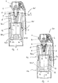
- Fig. 1 shows an irritation body 100, which has a one-piece base body or housing 101, with an ignition head 1 located in or on the upper part 100.1 .
- the ignition head 1 is screwed into the upper part 100.1 of the basic body 101, for example, for which purpose the upper part 100.1 has an ignition head receptacle 7.
- At least one blow-out opening 8, (9) is integrated around this receptacle 7.
- This opening (s) 8, 9 opens into a central chamber 10 which is used to receive an effect charge or an effect set 11.
- the chamber 10 is attached centrally and preferably symmetrically around the central axis M of the irritation body 100 in the lower part 100.2 of the base body 101.
- the ignition charge 6 and the chamber 10 are aligned or coordinated with one another in such a way that they open from above and preferably centrally the effect charge 11 of the chamber 10 can act and ignite it.
- At least one opening 12 is provided in the lower region of the chamber 10, which, like the upper openings 8 (9), serves to blow out the ignited effect set 11.
- the interfaces 13, 14 - between the chamber 10 and the upper openings 8, (9), and the lower opening 12 to the environment - can be closed by closure elements 15, 16.
- the closure elements 15, 16 can be light cardboard discs.
- the irritation body 100 ′ has several, preferably four to six, openings 12, 18, 19, 20 in the lower region of the chamber 10.
- the cross-sections of the upper opening (s) 8, (9) and of the lower openings 12, 18, 19, 20 are to be matched to one another in order to ensure that the pulses cancel each other out when the ignited effect charge emerges from these openings. More than two openings 8, 9 can also be provided in the upper area.
- the one or more lower bores or openings 12, 18, 19, 20 in the lower region of the chamber 10 are arranged eccentrically and unevenly distributed around the central axis M, thereby creating an asymmetry that also creates a preferred swirling of the ignited effect charge 11.
- the same can apply to the multiple openings 8, 9 in the upper region of the chamber 10.
- the central chamber 10 enables the effect charge 11 to be easily ignited when different quantities are received.
- the geometry of the chamber 10 can also be varied. However, if the irritation body 100 is designed in a modular manner, this idea can be implemented better and more simply.
- the irritation body 100, 100 'itself can be designed at least in two parts 102, 103 and modular.
- Each module 102, 103 represents an independent component of the irritation body 100, 100 ', which each comprises a module housing 102.1, 103.1 and can be combined with another module to form irritation bodies 100, 100' with different powers.
- the upper (first) module 102 preferably serves to accommodate the ignition head 1 along with the rocker arm 3 and ignition charge 6 with delay charge etc., the upper blow-out opening (s) 8, (9) also being integrated in the module 102.
- the lower module (s) 103 then comprises / comprise the chamber 10, which can be varied in size and / or geometry, and is characterized in that different inner chamber geometries can be integrated with the same module housing 103.1.
- the lower module 103 can have a chamber with a smaller volume or a smaller amount, which can be exchanged for another chamber with a larger volume and a larger amount.
- the corresponding component module is connected to the upper module 102 and attached to it.
- the lower (second) module 103 can be fastened to the upper module 102 or vice versa, for example.
- This attachment can be implemented by a latching connection 20.
- Other fixed connections can also be used.
- An axially introduced O-ring 21 is also arranged as a sealing ring between the two parts 102, 103.
Landscapes
- Engineering & Computer Science (AREA)
- General Engineering & Computer Science (AREA)
- Chemical & Material Sciences (AREA)
- Combustion & Propulsion (AREA)
- Tents Or Canopies (AREA)
- Golf Clubs (AREA)
- Catching Or Destruction (AREA)
Description
- Die Erfindung beschäftigt sich mit einem einfacher aufgebauten und herstellbaren Irritationskörper. Dazu weist dieser eine vorzugsweise einzelne zentrale Kammer zur Aufnahme einer Effektladung auf, insbesondere einer Knall erzeugenden Wirkladung. Um das gesamte Kammervolumen nutzen zu können, ist dabei vorgesehen, dass die Anzündladung mit Verzögerungssatz vorzugsweise mittig auf die Effektladung einwirkt, ohne in oder durch die Kammer selbst geführt zu werden. Dadurch kann das gesamte Kammervolumen für die Effektladung ausgenutzt werden. Durch diesen Aufbau ist es zudem möglich, den Irritationskörper modulartig auszuführen, wobei ein Modul die gesamte Anzündüng etc. aufnimmt und das andere die Kammer. Durch die Wahl des entsprechenden Moduls mit der benötigten Kammergröße kann die Leistungseigenschaft des Irritationskörpers in einfacher Art und Weise variiert und insbesondere erhöht werden.
- Irritationskörper dieser Art dienen zur nicht letalen Abwehr bzw. Verteidigung und werden u. a. zur Unterstützung bei Polizei- oder Militäreinsätzen eingesetzt. Sie ähneln einer Handgranate, die in der Regel manuell gezündet und danach weggeschleudert werden, jedoch selbst keine Fragmente bilden sollten. Die
US 2 094 561 A beschreibt einen solchen Irritationskörper. - Die
DE 199 44 486 C2 beschreibt einen Irritationskörper zum manuellen Zünden und Fortschleudern mit mehreren im Wesentlichen parallel zur Mittelachse des Behälters verlaufenden Abteilen, die Effektladungen aufnehmen, die zeitversetzt gezündet werden. - Mit der
DE 92 13 376 U1 wurde ein als Schockwaffe bezeichneter Irritationskörper offenbart, der mehrere Abteile aufweist, die Knall- oder Blitzladungen aufnehmen können. Der Irritationskörper weist eine Zündeinrichtung mit einem gemeinsamen Zündkanal auf, von dem aus über dessen Länge verteilt Stichbohrungen zu dem jeweiligen Abteil führen. - Aus der
DE 10 2004 059 991 B1 ist ein Irritationskörper mit einem Kipphebel bekannt, der aus einem Körper gebildet wird, in dem der Verzögerungssatz und die Wirkladung(en) eingebunden sind. Der Verzögerungssatz bzw. die Verzögerungsstrecke befindet sich dabei in einem separaten Röhrchen, das mit einem Zündkopf mit Hebel in den Irritationsgrundkörper eingebracht wird. Die Querschnitte der Ausblasöffnungen am oberen Ende des Grundkörpers des Irritationskörpers sind dabei kleiner gehalten als die Querschnitte der Ausblasöffnung am unteren Ende, wodurch die Ausblasöffnungen der beiden Seiten rückstoßneutral ausgebildet sind. Die Wirkladung ist ihrerseits in Kammern, so genannten Blitzkammern, untergebracht. In der Regel handelt es sich dabei um 6 Kammern, die ca. 8-10 g eines Blitz- bzw. Effektsatzes aufnehmen können. Diese Kammern sind symmetrisch um die Mittelachse des Irritationskörpers und von dieser beabstandet verteilt angeordnet und jede mit der Verzögerungszündstrecke verbunden. Die Befüllung der Kammern mit dem Effektsatz erfolgt in der Regel durch die Ausblasöffnungen von oben. Am oberen als auch am unteren Ende werden die Kammern durch Verschlusselemente abgedichtet. Diese als Pappscheiben ausgebildeten Verschlusselemente werden nach / mit Zündung der Effektladung bzw. des Effektsatzes in den einzelnen Kammern ausgestoßen und bilden ihrerseits Fragmente, was jedoch bei den vorgenannten Irritationskörpern unerwünscht ist. Die durch den Effektsatz erzeugten Effekte, beispielsweise Schall, verlassen durch die damit gewonnenen Ausblasöffnungen (oben und unten) den Irritationskörper. - Obwohl selten kann es gelegentlich zum Nichtzünden einer der Kammern kommen, sodass beispielsweise die erwünschte Schallleistung nicht erreicht wird.
- Mit der
US 2010/0224092 A1 wird die Weiterentwicklung eines Zünders für eine Schockgranate derUS 5,654,523 A beschrieben, wobei die Granate eine zentrale zylindrische Kammer zur Aufnahme der Effektladung aufweist, die über obere Öffnungen nach Entzündung austreten. Eine zentral durch diese Kammer geführte Anzündladung ragt ihrerseits bis zum Boden der Granate, wodurch eine recht gute Anzündung der in der zentralen Kammer befindlichen Effektladung gewährleistet sein sollte. Mit Zusammenbau der Granate bewirkt die Zündstrecke jedoch, dass auch hier wieder einzelne dezentrale Kammern gebildet werden, die dann symmetrisch von der Mittelachse durch die Zündstrecke selbst beabstandet sind. - Das nutzbare Volumen für derartige Sätze in den Kammern bzw. der zentralen Kammer ist durch diese Konstruktionen begrenzt. Die Verzögerungsstrecke zu den einzelnen Kammern ist ihrerseits eingepresst, was zu hohen Kosten bei deren Prüfung führt oder nimmt sehr viel Platz innerhalb der Kammer ein. Des Weiteren ergeben sich häufig Probleme beim Setzten der (Verbindungs-)Niete sowie beim Montieren der O-Ringe als Radialabdichtung. Auch das Aufsetzten der Hülse auf den Körper ist fertigungstechnisch sehr aufwändig. Die Befüllung der Kammern mit dem Satz erfolgt unter Vibration, um eine gleichmäßige Befüllung durch die schmalen Öffnungen zu garantieren.
- Die Erfindung stellt sich die Aufgabe, einen Irritationskörper aufzuzeigen, der diese nicht mehr aufweist.
- Gelöst wird die Aufgabe durch die Merkmale des Patentanspruchs 1 und des Patentanspruchs 2. Vorteilhafte Ausgestaltungen widerspiegeln sich in den Unteransprüchen.
- Der Erfindung liegt die Idee zugrunde, ähnlich der Granate nach
US 5,654,523 A eine zentrale Kammer zur Aufnahme der Wirkladung vorzusehen, jedoch die Zündstrecke von oben in die Kammer einwirken zu lassen, sodass nur eine obere Kontaktfläche zur Sammelkammer notwendig ist. Diese Zündstrecke kann dabei wie bisher zentral und mittig im oberen Bereich des Irritationskörpers eingebunden werden. Der gesamte Raum der Kammer steht damit zur Aufnahme der Effektladung zu Verfügung. Die gemeinsame Kammer kann über wenigstens eine, größere, bevorzugt jedoch über mehrere Befüllungsöffnungen mit dem Effektsatz befüllt werden. - Es versteht sich, dass die Einzelkammer auch in Teilkammern unterteilt werden kann, wenn dieses erwünscht ist, wobei die Anzündung des Effektsatzes ebenfalls von oben erfolgen kann und so auch in den längs zur Mittelachse verlaufenden Teilkammern gewährleistet wird.
- Die Kammer selbst kann je Irritationskörper unterschiedlich groß sein, sodass verschiedene Irritationskörper mit verschiedenen Leistungen angeboten werden können. In diesen Fällen kann die Wandstärke des Irritationskörpers im Bereich der Kammer variiert werden.
- In einer bevorzugten Ausführung wird der Irritationskörper jedoch modular ausgeführt. Dazu besteht dieser aus wenigsten zwei Modulen, einem oberen und einem unteren Modul, die zu einem, in Leistung und Volumen veränderbaren Irritationskörper zusammengefügt werden können. Das obere Teil enthält dabei bevorzugt den Verzögerungssatz mit Verzögerungsstrecke sowie die (Befüllungs-)öffnung(en) und dient zur Aufnahme des Zündkopfes. Das untere Teil umfasst dann die eigentliche Kammer(n) für die Aufnahme einer Wirk- bzw. Effektladung und die untere(n) Ausblasöffnung(en).
- Diese Modularität der beiden Körper macht es möglich, ein am oberen Modul des Irritationskörpers angepasstes unteres Modul mit verschiedenen Kammervolumen und / oder Ausblasanordnungen anzubringen. Die Schnittstellen zwischen der / den oberen Ausblasöffnungen und der Kammer sowie den unteren Ausblasöffnungen zur Umgebung werden durch je ein Verschlusselement verschlossen. Die feste Verbindung zwischen den beiden Modulen kann mittels Krimpen, Bördeln, Schweißen, etc. oder auch mittels leicht lösbaren Verbindungen wie Verschrauben, Rastungen, etc. geschaffen werden.
- Mit dieser modularen Ausführung können weitere Nachteile vermieden werden. So kann man auf das Setzten der Niete verzichten. Es wird nur noch ein O-Ring (zwischen dem oberen und dem unteren Modul) benötigt, der zudem als Axialdichtung eingebunden wird. Auch wird eine Hülse nicht mehr benötigt. Durch die größere(n) Befüllungsöffnung(en), die nicht mehr abhängig vom Durchmesser der einzelnen zu befüllenden Kammern ist / sind, wird ein vereinfachtes Befüllen erreicht. Durch die zentrale Kammer kann eine größere Menge der Effektladung aufgenommen werden. Diese Kammer bzw. Mengenaufnahme in der Kammer und damit des Irritationskörpers ist durch die modulare Gestaltung insbesondere des unteren Moduls variabel bzw. variierbar.
- Die Erhöhung des nutzbaren Volumens (um bis zu 100%) ist insbesondere beim Einsatz perchloratfreier Sätze von großem Vorteil.
- Anhand eines Ausführungsbeispiels mit Zeichnung soll die Erfindung näher erläutert werden.
- Es zeigt:
- Fig. 1
- eine erste Variante eines ein- als auch zweiteiligen Irritationskörper,
- Fig. 2
- eine weitere Variante eines ein- als auch zweiteiligen Irritationskörper.
-
Fig. 1 zeigt einen Irritationskörper 100, der einen einteiligen Grundkörper bzw. Gehäuse 101 aufweist, mit einem im bzw. am oberen Teil 100.1 befindlichen Zündkopf 1. Dieser Zündkopf 1 umfasst neben einem Kipphebel 3 ein Anzündhütchen 4 und ein Zündergehäuse 5 zur Aufnahme einer Anzündladung 6 mit Verzögerungssatz. Der Zündkopf 1 ist beispielsweise im oberen Teil 100.1 des Grundköpers 101 eingeschraubt, wozu das obere Teil 100.1 eine Zündkopfaufnahme 7 besitzt. Um diese Aufnahme 7 herum ist wenigsten eine Ausblasöffnung 8, (9) eingebunden. Diese Öffnung(en) 8, 9 mündet/n in eine zentrale Kammer 10, die zur Aufnahme einer Effektladung bzw. einer Effektsatzes 11 dient. Die Kammer 10 ist mittig und bevorzugt symmetrisch um die Mittelachse M des Irritationskörpers 100 im unteren Teil 100.2 des Grundkörpers 101 angebracht. Die Anzündladung 6 und die Kammer 10 sind so aufeinander ausgerichtet bzw. abgestimmt, dass diese von oben und bevorzugt zentral auf die Effektladung 11 der Kammer 10 einwirken und diese entzünden kann. Im unteren Bereich der Kammer 10 ist wenigstens eine Öffnung 12 vorgesehen, die wie die oberen Öffnungen 8 (9) zum Ausblasen des gezündeten Effektsatz 11 dient. - Die Schnittstellen 13, 14 - zwischen der Kammer 10 und den oberen Öffnungen 8, (9), sowie der unteren Öffnung 12 zur Umgebung - sind durch Verschlusselemente 15, 16 verschließbar. Die Verschlusselemente 15, 16 können leichte Pappscheiben sein.
- Bei der Einbindung nur einer (auch größeren) Öffnung 8, 12 sollte diese als exzentrische Bohrung ausgeführt werden, um so die Flugeigenschaft des Irritationskörpers beeinflussen zu können.
- In einer weiteren Variante nach
Fig. 2 weist der Irritationskörper 100' im unteren Bereich der Kammer 10 mehrere, vorzugsweise vier bis sechs, Öffnungen 12, 18, 19, 20 auf. Die Querschnitte der oberen Öffnung(en) 8, (9) als auch der unteren Öffnungen 12, 18, 19, 20 sind aufeinander abzustimmen, um zu erreichen, dass sich die Impulse beim Austreten der gezündeten Effektladung aus diesen Öffnungen gegenseitig aufheben. Auch im oberen Bereich können mehr als zwei Öffnungen 8, 9 vorgesehen sein. - Um eine Fragmentbildung zu reduzieren ist vorgesehen, dass die eine oder die mehreren unteren Bohrungen bzw. Öffnungen 12, 18, 19, 20 im unteren Bereich der Kammer 10 außermittig und ungleichmäßig um die Mittelachse M verteilt angeordnet sind, wodurch eine Asymmetrie geschaffen wird, die zudem eine bevorzugte Verwirbelung der gezündeten Effektladung 11 schafft. Gleiches kann für die mehreren Öffnungen 8, 9 im oberen Bereich der Kammer 10 gelten.
- Die zentrale Kammer 10 ermöglicht ein leichtes Anzünden der Effektladung 11 bei Aufnahme unterschiedlicher Mengen. Auch kann die Geometrie der Kammer 10 variiert werden. Wird der Irritationskörper 100 jedoch modulartig ausgeführt, kann diese Idee besser und einfacher umgesetzt werden.
- Wie in
Fig. 1 als auchFig. 2 erkennbar, kann der Irritationskörper 100, 100' selbst wenigstens zweiteilig 102, 103 und modular ausgeführt werden. Jedes Modul 102, 103 stellt ein eigenständiges Bauteil des Irritationskörreps 100, 100' dar, das jeweils ein Modulgehäuse 102.1, 103.1 umfasst und mit einem anderen Modul zu Irritationskörpern 100, 100' mit verschiedenen Leistungen zusammengefügt werden kann. - Das obere (ersten) Modul 102 dient dabei bevorzugt zur Aufnahme des Zündkopfes 1 nebst Kipphebel 3 und Anzündsatz 6 mit Verzögerungsladung etc., wobei auch die oberen Ausblasöffnung(en) 8, (9) im Modul 102 eingebunden sind.
- Das / die untere(n) Modul(e) 103 umfasst /umfassen dann die in ihrer Größe und / oder Geometrie variierbare Kammer 10 und zeichnet sich dabei dadurch aus, dass bei gleichem Modulgehäuse 103.1 verschiedene innere Kammergeometrien eingebunden werden können. So kann das untere Modul 103 beispielsweise eine Kammer mit geringerem Volumen oder geringerer Menge aufweisen, das gegen ein anderes mit größerem Volumen und größerer Menge austauschbar ist. Je nach dem, welche der Kammergrößen benötigt wird, wird das entsprechende Bauteilmodul mit dem oberen Modul 102 verbunden und an diesem befestigt.
- Ein derartiger Aufbau des Irritationskörpers 100, 100' ermöglicht, dass mit Hilfe des auswechselbaren unteren Moduls 103 eine einfachere Leistungsvariabilität geschaffen werden kann. Das untere (zweite) Modul 103 ist dabei beispielsweise am oberen Modul 102 oder umgekehrt befestigbar. Diese Befestigung kann durch eine Rastverbindung 20 realisiert werden. Andere feste Verbindungen sind ebenfalls nutzbar. Zwischen beiden Teilen 102, 103 ist zudem ein axial eingebrachter O-Ring 21 als Abdichtring angeordnet.
Claims (13)
- Irritationskörper (100,100') mit einem Grundkörper (101) und einem Zünderkopf (1) mit Kipphebel (3) und Anzündladung (6) mit Verzögerungssatz, mit wenigstens einer oberen (8, 9) und mit nur einer unteren Ausblasöffnung (12) sowie einer Effektladung (11), die in einer zentralen Kammer (10) des Irritationskörpers (100, 100') eingebunden ist, wobei die Anzündladung (6) und die Kammer (10) so aufeinander ausgerichtet bzw. abgestimmt sind, dass diese von oben auf die Effektladung (11) der Kammer (10) einwirken und diese entzünden kann, wobei der irritationskörper eine Mittelachse (M) hat,
dadurch gekennzeichnet, dass die eine untere Ausblasöffnung (12) als exzentrische Bohrung ausgeführt ist. - Irritationskörper (100, 100') mit einem Grundkörper (101) und einem Zündkopf (1) mit Kipphebel (3) und Anzündladung (6) mit Verzögerungssatz, mit mehreren oberen und mehreren unteren Ausblasöffnung (8, 9, 12, 18, 19, 20) sowie einer Effektladung (11), die in einer zentralen Kammer (10) des Irritationskörpers (100, 100') eingebunden ist, wobei die Anzündladung (6) und die Kammer (10) so aufeinander ausgerichtet bzw. abgestimmt sind, dass diese von oben auf die Effektladung (11) der Kammer (10) einwirken und diese entzünden kann, wobei der irritationskörper eine Mittelachse (M) hat, dadurch gekennzeichnet, dass die mehreren unteren Ausblasöffnungen (12, 18, 19, 20) im unteren Bereich der Kammer (10) und / oder die mehreren oberen Ausblasöffnungen (8, 9) im oberen Bereich der Kammer (10) außermittig und ungleichmäßig um die Mittelachse (M) verteilt eingebracht sind.
- Irritationskörper (100, 100') nach Anspruch 1 oder 2, dadurch gekennzeichnet, dass die Anzündladung (6) zentral von oben auf die Effektladung (11) der Kammer (10) einwirken kann.
- Irritationskörper (100, 100') nach einem der Ansprüche 1 bis 3, dadurch gekennzeichnet, dass die Kammer (10) mittig um die Mittelachse (M) des Irritationskörpers (100, 100') angeordnet ist.
- Irritationskörper (100, 100') nach Anspruch 4, dadurch gekennzeichnet, dass die Kammer (10) symmetrisch um die Mittelachse (M) angeordnet ist.
- Irritationskörper (100, 100') nach einem der Ansprüche 1 bis 5, dadurch gekennzeichnet, dass die Ausblasöffnungen (8, 9, 12, 18, 19, 20) zur Kammer (10) schräg verlaufend eingebunden sind.
- Irritationskörper (100, 100') nach einem der Ansprüche 1 bis 6, dadurch gekennzeichnet, dass die Kammer (10) unterschiedlich groß sein kann.
- Irritationskörper (100, 100') nach Anspruch 7, gekennzeichnet durch eine Variation einer Wandstärke des Irritationskörpers (100, 100') im Bereich der Kammer (10).
- Irritationskörper (100, 100') nach einem der Ansprüche 1 bis 8, dadurch gekennzeichnet, dass der Irritationskörper (100, 100') wenigstens zweiteilig und modular (102, 103) ausgeführt ist und jeweils ein Modulgehäuse (102.1, 103.1) umfasst.
- Irritationskörper (100, 100') nach Anspruch 9, dadurch gekennzeichnet, dass ein erstes, oberes Modul (102) zur Aufnahme zumindest des Zündkopfes (1) sowie der wenigstens einen oberen Ausblasöffnung (8, 9) und ein zweites, unteres Modul (103) zur Aufnahme der Kammer (10) und den wenigstens einen unteren Ausblasöffnung (12, 18, 19, 20) dienen und die Module (102, 103) voneinander getrennt aber auch miteinander verbunden werden können.
- Irritationskörper (100, 100') nach Anspruch 9 oder 10, dadurch gekennzeichnet, dass das / die untere(n) Modul(e) (103) eine in ihrer Größe und / oder Geometrie variierbare Kammer (10) umfasst /umfassen.
- Irritationskörper (100, 100') nach Anspruch 11, dadurch gekennzeichnet, dass bei gleichem Modulgehäuse (103.1) des unteren Moduls verschiedene innere Kammergeometrien eingebunden werden können.
- Irritationskörper (100, 100') nach einem der Ansprüche 1 bis 12, gekennzeichnet durch einen Einsatz perchloratfreier Sätze.
Priority Applications (1)
| Application Number | Priority Date | Filing Date | Title |
|---|---|---|---|
| PL11776710T PL2643654T3 (pl) | 2010-11-24 | 2011-10-27 | Korpus obezwładniający |
Applications Claiming Priority (2)
| Application Number | Priority Date | Filing Date | Title |
|---|---|---|---|
| DE102010052209.0A DE102010052209B4 (de) | 2010-11-24 | 2010-11-24 | Irritationskörper |
| PCT/EP2011/005421 WO2012069119A1 (de) | 2010-11-24 | 2011-10-27 | Irritationskörper |
Publications (2)
| Publication Number | Publication Date |
|---|---|
| EP2643654A1 EP2643654A1 (de) | 2013-10-02 |
| EP2643654B1 true EP2643654B1 (de) | 2020-12-16 |
Family
ID=44903158
Family Applications (1)
| Application Number | Title | Priority Date | Filing Date |
|---|---|---|---|
| EP11776710.3A Active EP2643654B1 (de) | 2010-11-24 | 2011-10-27 | Irritationskörper |
Country Status (4)
| Country | Link |
|---|---|
| EP (1) | EP2643654B1 (de) |
| DE (1) | DE102010052209B4 (de) |
| PL (1) | PL2643654T3 (de) |
| WO (1) | WO2012069119A1 (de) |
Families Citing this family (7)
| Publication number | Priority date | Publication date | Assignee | Title |
|---|---|---|---|---|
| DE102010052210B4 (de) * | 2010-11-24 | 2021-10-07 | Rheinmetall Waffe Munition Gmbh | Leistungsvariabler Irritationskörper |
| DE102012017031A1 (de) | 2012-08-28 | 2014-03-06 | Rheinmetall Waffe Munition Gmbh | lrritationswurfkörper |
| DE102016111947A1 (de) | 2016-06-30 | 2018-01-04 | Rheinmetall Waffe Munition Gmbh | Irritationskörper |
| DE102017108938B4 (de) | 2017-04-26 | 2023-05-17 | Rheinmetall Waffe Munition Gmbh | Irritationskörper mit Mitteln zur Einstellung einer Wirkleistung |
| DE102018125303A1 (de) | 2018-10-12 | 2020-04-16 | Rheinmetall Waffe Munition Gmbh | Anzündvorrichtung und Munition |
| DE102018128485B4 (de) | 2018-11-14 | 2022-05-05 | Rheinmetall Waffe Munition Gmbh | Elektronische Zündereinheit für einen Irritationskörper und Irritationskörper |
| CN115183635B (zh) * | 2022-08-09 | 2023-11-24 | 中国人民武装警察部队工程大学 | 具有两级延期发火组件和两级爆震机构的动能手榴弹 |
Citations (2)
| Publication number | Priority date | Publication date | Assignee | Title |
|---|---|---|---|---|
| DE9213376U1 (de) * | 1992-10-05 | 1992-12-10 | Nico Pyrotechnik Hanns-Jürgen Diederichs GmbH & Co KG, 2077 Trittau | Schockwaffe |
| US7963227B1 (en) * | 2009-01-05 | 2011-06-21 | CombMed Systems, Inc. | Multiple report stun grenade |
Family Cites Families (8)
| Publication number | Priority date | Publication date | Assignee | Title |
|---|---|---|---|---|
| US2094561A (en) * | 1934-09-19 | 1937-09-28 | Fed Lab Inc | Hand grenade |
| DE9210649U1 (de) | 1992-08-10 | 1992-11-05 | Nico Pyrotechnik Hanns-Jürgen Diederichs GmbH & Co KG, 2077 Trittau | Schockwaffe |
| DE9213375U1 (de) | 1992-10-05 | 1992-12-17 | Nico Pyrotechnik Hanns-Jürgen Diederichs GmbH & Co KG, 2077 Trittau | Schockwaffe |
| US5654523A (en) | 1995-05-02 | 1997-08-05 | Combined Systems, Inc. | Stun grenade |
| DE19944486C2 (de) | 1999-09-16 | 2003-06-26 | Nico Pyrotechnik | Irritationskörper |
| US6871594B1 (en) * | 2003-04-01 | 2005-03-29 | Randall P. Estrella | Reusable paint grenade |
| DE102004059991B4 (de) | 2004-12-13 | 2007-03-15 | Nico-Pyrotechnik Hanns-Jürgen Diederichs GmbH & Co. KG | Irritationskörper |
| CA2696587C (en) | 2009-03-09 | 2014-07-15 | John A. Kapeles | Fuze for stun grenade |
-
2010
- 2010-11-24 DE DE102010052209.0A patent/DE102010052209B4/de active Active
-
2011
- 2011-10-27 PL PL11776710T patent/PL2643654T3/pl unknown
- 2011-10-27 WO PCT/EP2011/005421 patent/WO2012069119A1/de not_active Ceased
- 2011-10-27 EP EP11776710.3A patent/EP2643654B1/de active Active
Patent Citations (2)
| Publication number | Priority date | Publication date | Assignee | Title |
|---|---|---|---|---|
| DE9213376U1 (de) * | 1992-10-05 | 1992-12-10 | Nico Pyrotechnik Hanns-Jürgen Diederichs GmbH & Co KG, 2077 Trittau | Schockwaffe |
| US7963227B1 (en) * | 2009-01-05 | 2011-06-21 | CombMed Systems, Inc. | Multiple report stun grenade |
Also Published As
| Publication number | Publication date |
|---|---|
| DE102010052209A1 (de) | 2012-05-24 |
| EP2643654A1 (de) | 2013-10-02 |
| WO2012069119A1 (de) | 2012-05-31 |
| DE102010052209B4 (de) | 2021-10-07 |
| PL2643654T3 (pl) | 2021-08-09 |
Similar Documents
| Publication | Publication Date | Title |
|---|---|---|
| EP2643653B1 (de) | Leistungsvariabler irritationskörper | |
| EP2643654B1 (de) | Irritationskörper | |
| EP1847797B1 (de) | Umschaltbare Ladung | |
| DE2105295C1 (de) | Pulverkörper für hülsenlose Munition | |
| DE69218650T2 (de) | Behälter, vorgesehen mit elektrischen Verbindungsmitteln | |
| WO2006063564A1 (de) | Irritationskörper | |
| DE2826497A1 (de) | Treibspiegelgeschoss mit pyrotechnischem satz | |
| EP0147661A1 (de) | Druckgasbetätigtes mechanisches Kraftelement | |
| EP0341543B1 (de) | Patrone mit Flintenlaufgeschoss | |
| DE9213375U1 (de) | Schockwaffe | |
| DE2027358A1 (de) | Selbstangetriebenes Geschoß für Feuerwaffen und Schießwerkzeuge | |
| DE102007033832A1 (de) | Munition mit einer aus mehreren Teilladungen bestehenden Treibladung | |
| DE2442545C2 (de) | Rohrverbindungsvorrichtung für Rohrabzweigungen | |
| DE19830134A1 (de) | Lechtrakete für einen Hubschrauber und Verfahren zum Erzeugen einer Köderspur | |
| DE3048595A1 (de) | "gefechtskopf fuer tarn- und/oder taeuschzwecke" | |
| DE60309690T2 (de) | Pyrotechnische vorrichtung mit zündverzögerung | |
| DE2743770C2 (de) | Vorrichtung zum elektrischen Anzünden einer pyrotechnischen Ladung | |
| DE19715738A1 (de) | Klemmverbinder zum Verbinden einer Sprengschnur mit einem Zünder | |
| EP1795859A1 (de) | Multifunktionales Sprengsystem | |
| DE102013007784A1 (de) | Wurfkörper, insbesondere Handwurfkörper | |
| DE102018125845B3 (de) | Druckgaswaffe | |
| DE1254510B (de) | Nebelkerze | |
| EP3011257B1 (de) | Abstandselement, hohlladungskörper und sprengsatz sowie zugehöriger bausatz | |
| DE702526C (de) | Schiessvorrichtung zum Durchloechern der Verrohrung von Bohrloechern | |
| DE246284C (de) |
Legal Events
| Date | Code | Title | Description |
|---|---|---|---|
| PUAI | Public reference made under article 153(3) epc to a published international application that has entered the european phase |
Free format text: ORIGINAL CODE: 0009012 |
|
| 17P | Request for examination filed |
Effective date: 20130429 |
|
| AK | Designated contracting states |
Kind code of ref document: A1 Designated state(s): AL AT BE BG CH CY CZ DE DK EE ES FI FR GB GR HR HU IE IS IT LI LT LU LV MC MK MT NL NO PL PT RO RS SE SI SK SM TR |
|
| DAX | Request for extension of the european patent (deleted) | ||
| 17Q | First examination report despatched |
Effective date: 20161013 |
|
| STAA | Information on the status of an ep patent application or granted ep patent |
Free format text: STATUS: EXAMINATION IS IN PROGRESS |
|
| GRAP | Despatch of communication of intention to grant a patent |
Free format text: ORIGINAL CODE: EPIDOSNIGR1 |
|
| STAA | Information on the status of an ep patent application or granted ep patent |
Free format text: STATUS: GRANT OF PATENT IS INTENDED |
|
| INTG | Intention to grant announced |
Effective date: 20200717 |
|
| GRAS | Grant fee paid |
Free format text: ORIGINAL CODE: EPIDOSNIGR3 |
|
| GRAA | (expected) grant |
Free format text: ORIGINAL CODE: 0009210 |
|
| STAA | Information on the status of an ep patent application or granted ep patent |
Free format text: STATUS: THE PATENT HAS BEEN GRANTED |
|
| AK | Designated contracting states |
Kind code of ref document: B1 Designated state(s): AL AT BE BG CH CY CZ DE DK EE ES FI FR GB GR HR HU IE IS IT LI LT LU LV MC MK MT NL NO PL PT RO RS SE SI SK SM TR |
|
| REG | Reference to a national code |
Ref country code: GB Ref legal event code: FG4D Free format text: NOT ENGLISH |
|
| REG | Reference to a national code |
Ref country code: DE Ref legal event code: R096 Ref document number: 502011017014 Country of ref document: DE |
|
| REG | Reference to a national code |
Ref country code: IE Ref legal event code: FG4D Free format text: LANGUAGE OF EP DOCUMENT: GERMAN |
|
| REG | Reference to a national code |
Ref country code: AT Ref legal event code: REF Ref document number: 1345993 Country of ref document: AT Kind code of ref document: T Effective date: 20210115 |
|
| REG | Reference to a national code |
Ref country code: SE Ref legal event code: TRGR |
|
| REG | Reference to a national code |
Ref country code: NL Ref legal event code: FP |
|
| PG25 | Lapsed in a contracting state [announced via postgrant information from national office to epo] |
Ref country code: GR Free format text: LAPSE BECAUSE OF FAILURE TO SUBMIT A TRANSLATION OF THE DESCRIPTION OR TO PAY THE FEE WITHIN THE PRESCRIBED TIME-LIMIT Effective date: 20210317 Ref country code: FI Free format text: LAPSE BECAUSE OF FAILURE TO SUBMIT A TRANSLATION OF THE DESCRIPTION OR TO PAY THE FEE WITHIN THE PRESCRIBED TIME-LIMIT Effective date: 20201216 Ref country code: RS Free format text: LAPSE BECAUSE OF FAILURE TO SUBMIT A TRANSLATION OF THE DESCRIPTION OR TO PAY THE FEE WITHIN THE PRESCRIBED TIME-LIMIT Effective date: 20201216 Ref country code: NO Free format text: LAPSE BECAUSE OF FAILURE TO SUBMIT A TRANSLATION OF THE DESCRIPTION OR TO PAY THE FEE WITHIN THE PRESCRIBED TIME-LIMIT Effective date: 20210316 |
|
| PG25 | Lapsed in a contracting state [announced via postgrant information from national office to epo] |
Ref country code: LV Free format text: LAPSE BECAUSE OF FAILURE TO SUBMIT A TRANSLATION OF THE DESCRIPTION OR TO PAY THE FEE WITHIN THE PRESCRIBED TIME-LIMIT Effective date: 20201216 Ref country code: BG Free format text: LAPSE BECAUSE OF FAILURE TO SUBMIT A TRANSLATION OF THE DESCRIPTION OR TO PAY THE FEE WITHIN THE PRESCRIBED TIME-LIMIT Effective date: 20210316 |
|
| PG25 | Lapsed in a contracting state [announced via postgrant information from national office to epo] |
Ref country code: HR Free format text: LAPSE BECAUSE OF FAILURE TO SUBMIT A TRANSLATION OF THE DESCRIPTION OR TO PAY THE FEE WITHIN THE PRESCRIBED TIME-LIMIT Effective date: 20201216 |
|
| REG | Reference to a national code |
Ref country code: LT Ref legal event code: MG9D |
|
| PG25 | Lapsed in a contracting state [announced via postgrant information from national office to epo] |
Ref country code: SM Free format text: LAPSE BECAUSE OF FAILURE TO SUBMIT A TRANSLATION OF THE DESCRIPTION OR TO PAY THE FEE WITHIN THE PRESCRIBED TIME-LIMIT Effective date: 20201216 Ref country code: EE Free format text: LAPSE BECAUSE OF FAILURE TO SUBMIT A TRANSLATION OF THE DESCRIPTION OR TO PAY THE FEE WITHIN THE PRESCRIBED TIME-LIMIT Effective date: 20201216 Ref country code: CZ Free format text: LAPSE BECAUSE OF FAILURE TO SUBMIT A TRANSLATION OF THE DESCRIPTION OR TO PAY THE FEE WITHIN THE PRESCRIBED TIME-LIMIT Effective date: 20201216 Ref country code: LT Free format text: LAPSE BECAUSE OF FAILURE TO SUBMIT A TRANSLATION OF THE DESCRIPTION OR TO PAY THE FEE WITHIN THE PRESCRIBED TIME-LIMIT Effective date: 20201216 Ref country code: PT Free format text: LAPSE BECAUSE OF FAILURE TO SUBMIT A TRANSLATION OF THE DESCRIPTION OR TO PAY THE FEE WITHIN THE PRESCRIBED TIME-LIMIT Effective date: 20210416 Ref country code: RO Free format text: LAPSE BECAUSE OF FAILURE TO SUBMIT A TRANSLATION OF THE DESCRIPTION OR TO PAY THE FEE WITHIN THE PRESCRIBED TIME-LIMIT Effective date: 20201216 Ref country code: SK Free format text: LAPSE BECAUSE OF FAILURE TO SUBMIT A TRANSLATION OF THE DESCRIPTION OR TO PAY THE FEE WITHIN THE PRESCRIBED TIME-LIMIT Effective date: 20201216 |
|
| REG | Reference to a national code |
Ref country code: DE Ref legal event code: R097 Ref document number: 502011017014 Country of ref document: DE |
|
| PG25 | Lapsed in a contracting state [announced via postgrant information from national office to epo] |
Ref country code: IS Free format text: LAPSE BECAUSE OF FAILURE TO SUBMIT A TRANSLATION OF THE DESCRIPTION OR TO PAY THE FEE WITHIN THE PRESCRIBED TIME-LIMIT Effective date: 20210416 |
|
| PLBE | No opposition filed within time limit |
Free format text: ORIGINAL CODE: 0009261 |
|
| STAA | Information on the status of an ep patent application or granted ep patent |
Free format text: STATUS: NO OPPOSITION FILED WITHIN TIME LIMIT |
|
| PG25 | Lapsed in a contracting state [announced via postgrant information from national office to epo] |
Ref country code: AL Free format text: LAPSE BECAUSE OF FAILURE TO SUBMIT A TRANSLATION OF THE DESCRIPTION OR TO PAY THE FEE WITHIN THE PRESCRIBED TIME-LIMIT Effective date: 20201216 Ref country code: IT Free format text: LAPSE BECAUSE OF FAILURE TO SUBMIT A TRANSLATION OF THE DESCRIPTION OR TO PAY THE FEE WITHIN THE PRESCRIBED TIME-LIMIT Effective date: 20201216 |
|
| 26N | No opposition filed |
Effective date: 20210917 |
|
| PG25 | Lapsed in a contracting state [announced via postgrant information from national office to epo] |
Ref country code: DK Free format text: LAPSE BECAUSE OF FAILURE TO SUBMIT A TRANSLATION OF THE DESCRIPTION OR TO PAY THE FEE WITHIN THE PRESCRIBED TIME-LIMIT Effective date: 20201216 Ref country code: ES Free format text: LAPSE BECAUSE OF FAILURE TO SUBMIT A TRANSLATION OF THE DESCRIPTION OR TO PAY THE FEE WITHIN THE PRESCRIBED TIME-LIMIT Effective date: 20201216 |
|
| REG | Reference to a national code |
Ref country code: DE Ref legal event code: R082 Ref document number: 502011017014 Country of ref document: DE Representative=s name: DREISS PATENTANWAELTE PARTG MBB, DE |
|
| PG25 | Lapsed in a contracting state [announced via postgrant information from national office to epo] |
Ref country code: SI Free format text: LAPSE BECAUSE OF FAILURE TO SUBMIT A TRANSLATION OF THE DESCRIPTION OR TO PAY THE FEE WITHIN THE PRESCRIBED TIME-LIMIT Effective date: 20201216 |
|
| REG | Reference to a national code |
Ref country code: DE Ref legal event code: R082 Ref document number: 502011017014 Country of ref document: DE Representative=s name: DREISS PATENTANWAELTE PARTG MBB, DE |
|
| REG | Reference to a national code |
Ref country code: CH Ref legal event code: PL |
|
| PG25 | Lapsed in a contracting state [announced via postgrant information from national office to epo] |
Ref country code: IS Free format text: LAPSE BECAUSE OF FAILURE TO SUBMIT A TRANSLATION OF THE DESCRIPTION OR TO PAY THE FEE WITHIN THE PRESCRIBED TIME-LIMIT Effective date: 20210416 |
|
| REG | Reference to a national code |
Ref country code: BE Ref legal event code: MM Effective date: 20211031 |
|
| PG25 | Lapsed in a contracting state [announced via postgrant information from national office to epo] |
Ref country code: MC Free format text: LAPSE BECAUSE OF FAILURE TO SUBMIT A TRANSLATION OF THE DESCRIPTION OR TO PAY THE FEE WITHIN THE PRESCRIBED TIME-LIMIT Effective date: 20201216 |
|
| PG25 | Lapsed in a contracting state [announced via postgrant information from national office to epo] |
Ref country code: LU Free format text: LAPSE BECAUSE OF NON-PAYMENT OF DUE FEES Effective date: 20211027 Ref country code: BE Free format text: LAPSE BECAUSE OF NON-PAYMENT OF DUE FEES Effective date: 20211031 |
|
| PG25 | Lapsed in a contracting state [announced via postgrant information from national office to epo] |
Ref country code: LI Free format text: LAPSE BECAUSE OF NON-PAYMENT OF DUE FEES Effective date: 20211031 Ref country code: CH Free format text: LAPSE BECAUSE OF NON-PAYMENT OF DUE FEES Effective date: 20211031 |
|
| PG25 | Lapsed in a contracting state [announced via postgrant information from national office to epo] |
Ref country code: IE Free format text: LAPSE BECAUSE OF NON-PAYMENT OF DUE FEES Effective date: 20211027 |
|
| REG | Reference to a national code |
Ref country code: AT Ref legal event code: MM01 Ref document number: 1345993 Country of ref document: AT Kind code of ref document: T Effective date: 20211027 |
|
| PG25 | Lapsed in a contracting state [announced via postgrant information from national office to epo] |
Ref country code: AT Free format text: LAPSE BECAUSE OF NON-PAYMENT OF DUE FEES Effective date: 20211027 |
|
| PG25 | Lapsed in a contracting state [announced via postgrant information from national office to epo] |
Ref country code: HU Free format text: LAPSE BECAUSE OF FAILURE TO SUBMIT A TRANSLATION OF THE DESCRIPTION OR TO PAY THE FEE WITHIN THE PRESCRIBED TIME-LIMIT; INVALID AB INITIO Effective date: 20111027 Ref country code: CY Free format text: LAPSE BECAUSE OF FAILURE TO SUBMIT A TRANSLATION OF THE DESCRIPTION OR TO PAY THE FEE WITHIN THE PRESCRIBED TIME-LIMIT Effective date: 20201216 |
|
| PG25 | Lapsed in a contracting state [announced via postgrant information from national office to epo] |
Ref country code: MK Free format text: LAPSE BECAUSE OF FAILURE TO SUBMIT A TRANSLATION OF THE DESCRIPTION OR TO PAY THE FEE WITHIN THE PRESCRIBED TIME-LIMIT Effective date: 20201216 |
|
| PG25 | Lapsed in a contracting state [announced via postgrant information from national office to epo] |
Ref country code: TR Free format text: LAPSE BECAUSE OF FAILURE TO SUBMIT A TRANSLATION OF THE DESCRIPTION OR TO PAY THE FEE WITHIN THE PRESCRIBED TIME-LIMIT Effective date: 20201216 |
|
| PG25 | Lapsed in a contracting state [announced via postgrant information from national office to epo] |
Ref country code: MT Free format text: LAPSE BECAUSE OF FAILURE TO SUBMIT A TRANSLATION OF THE DESCRIPTION OR TO PAY THE FEE WITHIN THE PRESCRIBED TIME-LIMIT Effective date: 20201216 |
|
| PGFP | Annual fee paid to national office [announced via postgrant information from national office to epo] |
Ref country code: NL Payment date: 20241021 Year of fee payment: 14 |
|
| PGFP | Annual fee paid to national office [announced via postgrant information from national office to epo] |
Ref country code: PL Payment date: 20241017 Year of fee payment: 14 |
|
| PGFP | Annual fee paid to national office [announced via postgrant information from national office to epo] |
Ref country code: GB Payment date: 20241022 Year of fee payment: 14 |
|
| PGFP | Annual fee paid to national office [announced via postgrant information from national office to epo] |
Ref country code: FR Payment date: 20241021 Year of fee payment: 14 |
|
| PGFP | Annual fee paid to national office [announced via postgrant information from national office to epo] |
Ref country code: SE Payment date: 20241021 Year of fee payment: 14 |
|
| PGFP | Annual fee paid to national office [announced via postgrant information from national office to epo] |
Ref country code: DE Payment date: 20251021 Year of fee payment: 15 |