EP2643702B1 - Structure d'accéléromètre bi-axial résonant du type micro-électromécanique - Google Patents
Structure d'accéléromètre bi-axial résonant du type micro-électromécanique Download PDFInfo
- Publication number
- EP2643702B1 EP2643702B1 EP11799844.3A EP11799844A EP2643702B1 EP 2643702 B1 EP2643702 B1 EP 2643702B1 EP 11799844 A EP11799844 A EP 11799844A EP 2643702 B1 EP2643702 B1 EP 2643702B1
- Authority
- EP
- European Patent Office
- Prior art keywords
- inertial mass
- resonant
- elastic elements
- detection
- elements
- Prior art date
- Legal status (The legal status is an assumption and is not a legal conclusion. Google has not performed a legal analysis and makes no representation as to the accuracy of the status listed.)
- Active
Links
Images




Classifications
-
- G—PHYSICS
- G01—MEASURING; TESTING
- G01P—MEASURING LINEAR OR ANGULAR SPEED, ACCELERATION, DECELERATION, OR SHOCK; INDICATING PRESENCE, ABSENCE, OR DIRECTION, OF MOVEMENT
- G01P15/00—Measuring acceleration; Measuring deceleration; Measuring shock, i.e. sudden change of acceleration
- G01P15/02—Measuring acceleration; Measuring deceleration; Measuring shock, i.e. sudden change of acceleration by making use of inertia forces using solid seismic masses
- G01P15/08—Measuring acceleration; Measuring deceleration; Measuring shock, i.e. sudden change of acceleration by making use of inertia forces using solid seismic masses with conversion into electric or magnetic values
- G01P15/097—Measuring acceleration; Measuring deceleration; Measuring shock, i.e. sudden change of acceleration by making use of inertia forces using solid seismic masses with conversion into electric or magnetic values by vibratory elements
-
- G—PHYSICS
- G01—MEASURING; TESTING
- G01P—MEASURING LINEAR OR ANGULAR SPEED, ACCELERATION, DECELERATION, OR SHOCK; INDICATING PRESENCE, ABSENCE, OR DIRECTION, OF MOVEMENT
- G01P15/00—Measuring acceleration; Measuring deceleration; Measuring shock, i.e. sudden change of acceleration
- G01P15/02—Measuring acceleration; Measuring deceleration; Measuring shock, i.e. sudden change of acceleration by making use of inertia forces using solid seismic masses
- G01P15/08—Measuring acceleration; Measuring deceleration; Measuring shock, i.e. sudden change of acceleration by making use of inertia forces using solid seismic masses with conversion into electric or magnetic values
- G01P15/0888—Measuring acceleration; Measuring deceleration; Measuring shock, i.e. sudden change of acceleration by making use of inertia forces using solid seismic masses with conversion into electric or magnetic values for indicating angular acceleration
-
- G—PHYSICS
- G01—MEASURING; TESTING
- G01P—MEASURING LINEAR OR ANGULAR SPEED, ACCELERATION, DECELERATION, OR SHOCK; INDICATING PRESENCE, ABSENCE, OR DIRECTION, OF MOVEMENT
- G01P15/00—Measuring acceleration; Measuring deceleration; Measuring shock, i.e. sudden change of acceleration
- G01P15/18—Measuring acceleration; Measuring deceleration; Measuring shock, i.e. sudden change of acceleration in two or more dimensions
-
- G—PHYSICS
- G01—MEASURING; TESTING
- G01P—MEASURING LINEAR OR ANGULAR SPEED, ACCELERATION, DECELERATION, OR SHOCK; INDICATING PRESENCE, ABSENCE, OR DIRECTION, OF MOVEMENT
- G01P15/00—Measuring acceleration; Measuring deceleration; Measuring shock, i.e. sudden change of acceleration
- G01P15/02—Measuring acceleration; Measuring deceleration; Measuring shock, i.e. sudden change of acceleration by making use of inertia forces using solid seismic masses
- G01P15/08—Measuring acceleration; Measuring deceleration; Measuring shock, i.e. sudden change of acceleration by making use of inertia forces using solid seismic masses with conversion into electric or magnetic values
- G01P2015/0805—Measuring acceleration; Measuring deceleration; Measuring shock, i.e. sudden change of acceleration by making use of inertia forces using solid seismic masses with conversion into electric or magnetic values being provided with a particular type of spring-mass-system for defining the displacement of a seismic mass due to an external acceleration
- G01P2015/0808—Measuring acceleration; Measuring deceleration; Measuring shock, i.e. sudden change of acceleration by making use of inertia forces using solid seismic masses with conversion into electric or magnetic values being provided with a particular type of spring-mass-system for defining the displacement of a seismic mass due to an external acceleration for defining in-plane movement of the mass, i.e. movement of the mass in the plane of the substrate
- G01P2015/082—Measuring acceleration; Measuring deceleration; Measuring shock, i.e. sudden change of acceleration by making use of inertia forces using solid seismic masses with conversion into electric or magnetic values being provided with a particular type of spring-mass-system for defining the displacement of a seismic mass due to an external acceleration for defining in-plane movement of the mass, i.e. movement of the mass in the plane of the substrate for two degrees of freedom of movement of a single mass
Definitions
- the present invention relates to a resonant biaxial accelerometer structure of a MEMS (microelectromechanical system) type, in particular capable of detecting with high electrical performance two independent components of acceleration in a plane.
- MEMS microelectromechanical system
- MEMS accelerometers are currently used, thanks to their extremely compact dimensions, low levels of consumption, and good electrical performance, in a wide range of fields of application, amongst which the automotive industry, monitoring of vibrations, and portable electronics.
- MEMS accelerometers proposed in the literature and currently present on the market can be generally grouped into three classes, on the basis of the principle of detection used by the corresponding microelectromechanical detection structure: capacitive, resonant, and piezoresistive.
- the external acceleration to be measured produces a detectable shift of the resonance frequency of the microelectromechanical structure, or of some part thereof.
- the resonant detection as compared to other measurement principles, presents the advantage of offering a direct frequency output, high sensitivity, and wide dynamic range.
- the external acceleration is detected in terms of a shift in the resonance frequency of a resonant element, in general beam-shaped, coupled to an inertial mass (the so-called “proof mass” or “free mass”).
- a and I are, respectively, the length, the area of the cross section, and the moment of inertia of the resonant element
- ⁇ is the mass density of the material of which it is made
- E is the elastic modulus
- c and ⁇ are coefficients, the value of which depends, in a known way, upon the conditions of constraint of the beam that constitutes said resonant element.
- the various MEMS resonant accelerometers so far proposed differ from the standpoint of the geometries envisaged for the microelectromechanical detection structure (in particular for the different arrangements of the resonant element with respect to the inertial mass), and consequently for the electrical characteristics that derive therefrom, for example as regards the amplification of the axial force and consequently the sensitivity in the detection of acceleration.
- the sensitivity of resonant accelerometers is generally defined as the variation in frequency generated by an external acceleration the equal to 1g.
- Known resonant accelerometers obtained through techniques of surface micromachining typically have a sensitivity that starts from some tens of Hz/g and does not exceed 200 Hz/g, and, at least some of them, have rather large dimensions.
- the MEMS resonant accelerometers proposed so far are for the most part of a uniaxial type, i.e., able to detect, with a single inertial detection mass, a single component of acceleration directed along a given axis of detection. Consequently, it is necessary to replicate the microelectromechanical structures proposed, each provided with a corresponding inertial mass, to obtain a detection of components of acceleration directed along a number of axes of detection.
- US 4 851 080 A discloses a resonant accelerometer, including a mass suspended by pairs of resonating arms. One pair of arms lies on a first axis through the mass. Another pair of arms lies on a second axis through the mass, perpendicular to the first axis. Acceleration of the mass is detected by a measured change in resonant frequency of the arms of a pair. The resonating arms are directly attached to the mass.
- US 2006/096378 A1 discloses a uni-axial accelerometer structure, including a moveable seismic mass capable of moving translationally along a sensitive axis under the effect of an acceleration, and a resonator that can vibrate and be subjected to a tensile or compressive force depending on the direction of the acceleration.
- the resonator is placed symmetrically with respect to an axis of symmetry of the structure, this axis being parallel to the sensitive axis and passing through the center of gravity of the seismic mass.
- the structure further includes amplification means for amplifying the acceleration force, which comprise two rigid terminations of the resonator and two pairs of micromachined elastic arms, coupled to each rigid termination, and arranged at an angle with respect to the sensitive axis.
- US 6 389 898 B1 discloses a microsensor with a resonator structure, which is excited by first electrical signals to oscillate, and emits second electrical signals in dependence on the measuring variable; a heating element, supplied with at least one of the first electrical signals, is arranged on the resonator structure for the thermal excitations of oscillations.
- the aim of the present invention is consequently to provide a microelectromechanical structure for a resonant accelerometer that will present improved physical and electrical characteristics, and in particular that will enable a biaxial detection of components of accelerations acting along at least two axes of detection in a plane.
- a microelectromechanical structure for a resonant accelerometer is consequently provided, as defined in the annexed claims.
- one aspect of the present invention envisages the use of a single inertial mass for the detection of at least two independent components of acceleration in a plane, in particular coinciding with a plane of main extension of said inertial mass.
- a single inertial mass for the detection of at least two independent components of acceleration in a plane, in particular coinciding with a plane of main extension of said inertial mass.
- resonant elements for detecting the aforesaid components of acceleration according to the principle of the variation of the resonance frequency (see in this regard the foregoing description).
- Figure 1 shows a first embodiment of a microelectromechanical detection structure, designated as a whole by 1, of a resonant biaxial accelerometer.
- the microelectromechanical detection structure 1 is produced in an integrated way, with the surface-micromachining semiconductor techniques, in particular starting from a body made of semiconductor material (such as silicon).
- the microelectromechanical detection structure 1 comprises a single inertial mass 2, which has, for example, a generically square shape in a plane xy, corresponding to a principal plane of extension of its own, defined by a first axis x and by a second axis y, which correspond moreover to the directions of detection of the resonant biaxial accelerometer (as will be clarified hereinafter).
- the inertial mass 2 has a negligible dimension in the direction orthogonal to said plane xy, along a third axis z, which defines, with the aforesaid first and second axes x, y, a set of three orthogonal axes.
- the inertial mass 2 has, in said first embodiment, four portions of mass 2a- 2d, which have, for example, a substantially square shape in the plane xy and define an external boundary of the mass in said plane xy, and a central portion 2e, which radiuses the portions of mass 2a-2d at the centre and has also, for example, a substantially square shape in plan view.
- the inertial mass 2 moreover has a centroidal axis (defined as the axis passing through its centre of gravity G, in this case coinciding with the geometrical centre of the central portion 2e), which moreover represents an axis of symmetry for the microelectromechanical detection structure 1 and is directed orthogonal to the plane xy.
- the portions of mass 2a-2d define, in adjacent pairs, respective windows 4, numbering four in all, which extend starting from the central portion 2e and open towards the outside of the inertial mass 2.
- windows 4 of a first pair extend from opposite sides of the central portion 2e along the second axis y
- the remaining windows 4 extend along the first axis x, and are also set on opposite sides of the central portion 2e.
- the structure of the inertial mass 2 is symmetrical with respect to axes parallel to the axes x and y and passing through the geometrical centre of the central portion 2e (centre of gravity G).
- the inertial mass 2 is anchored to a substrate (not illustrated, for example a substrate made of semiconductor material, such as silicon) so as to be suspended above said substrate, with the plane xy substantially parallel to a top surface of said substrate.
- a substrate not illustrated, for example a substrate made of semiconductor material, such as silicon
- the inertial mass 2 is elastically coupled to first anchorages 6, numbering four in all in the first embodiment illustrated, set externally to said inertial mass 2, and aligned in pairs to the windows 4 in the direction of the prolongation of said windows 4, along the first axis x or the second axis y.
- the first anchorages 6 are for example constituted by pillars that extend as far as, and are mechanically connected to, the substrate.
- the inertial mass 2 is connected to the aforesaid first anchorages 6 by means of respective elastic elements 8 (which are also four in number in the embodiment illustrated), as a whole configured so as to maintain the inertial mass 2 suspended above the substrate and enable at least one first linear movement of translation and one second linear movement of translation thereof (with respect to said substrate), respectively along the first axis x and the second axis y, and as to prevent movements thereof out of said plane xy.
- Each elastic element 8 comprises: a first portion 8a, constituted by a rectilinear linear spring (the so-called “single beam”), which extends along the first axis x or second axis y starting from an external lateral surface of the central portion 2e of the inertial mass 2 (centrally with respect thereto), within a respective window 4; a second portion 8b, connected to the first portion 8a, and constituted by a folded spring (the so-called “folded beam”), having extension in a direction transverse to the first portion 8a, in particular along the second axis y or first axis x (the second portion 8b is hence constituted by a plurality of rectilinear springs, parallel to one another, which have main extension in the aforesaid transverse direction and are radiused to one another at the corresponding ends); and a third portion 8c, connected to the second portion 8b and constituted once again by a rectilinear spring, having extension along the first axis
- the elastic elements 8 are very thin (the corresponding constituent portions have, that is, a length in the direction of extension much greater than the corresponding width).
- the microelectromechanical detection structure 1 further comprises a resonant part, formed by four resonant elements 10a-10d, each of which is constituted by a thin resonant beam.
- the resonant elements 10a-10d are set externally to the inertial mass 2, with respect to the plane xy, and extend parallel in pairs along the first axis x or the second axis y, moreover parallel to the second portion 8b of an associated elastic element 8, externally thereto.
- each resonant element 10a-10d is rigidly constrained to the substrate at a first end thereof, by means of a respective second anchorage 12 (once again constituted, for example, by a pillar that extends as far as, and is connected to, the substrate), and extends starting from said second anchorage 12 until it joins, with a second end of its own, a respective elastic element 8, in particular the third portion 8c of said elastic element 8, in close proximity of the respective first anchorage 6 of said elastic element 8.
- the point of connection of the resonant element 10a-10d to the respective elastic element 8 is designated by c.
- Each resonant element 10a-10d hence forms with the part of the third portion 8c of the respective elastic element 8, comprised between the point of connection c and the corresponding first anchorage 6, an L-shaped resonant structure.
- Each resonant element 10a-10d is hence mechanically coupled to the inertial mass 2 through a respective elastic element 8.
- said configuration enables high values of detection sensitivity to be obtained with an inertial mass 2 of contained dimensions in so far as the intermediate presence of the elastic elements 8 prevents the stiffness of the resonant elements 10a-10d from hindering directly the inertial mass 2 and hence reducing the excursion of the movements thereof upon detection of the external accelerations.
- the position of the point of connection c in the close proximity of the first anchorages 6 is a factor that determines the electrical characteristics of the resonant detection structure (in terms of amplification of the axial force in response to an external acceleration, and hence of the detection sensitivity).
- the configuration described of the resonant elements 10a-10d moreover advantageously enables increase in the interval of linear behaviour in frequency of the microelectromechanical detection structure 1.
- the presence of the part of the third portion 8c of the elastic elements 8, comprised between the point of connection c and the corresponding first anchorage 6, of small dimensions causes the linear behaviour of each resonant element 10a-10d not to depart substantially from that of standard resonators constrained at both ends (the so-called "double-clamped" resonators), while the non-linear behaviour is instead considerably improved.
- the microelectromechanical detection structure 1 further comprises, for each resonant element 10a-10d, a pair of electrodes 13, 14, arranged parallel to one another and parallel to the corresponding resonant element 10a- 10d, on opposite sides of said resonant element 10a- 10d with respect to the first axis x or second axis y.
- a first electrode 13 is used to send the associated resonant element 10a-10d into a resonance condition by applying an appropriate difference of electrical potential
- a second electrode 14 is used as detection electrode, for detecting, by means of a variation of the capacitive coupling with the resonant element 10a-10d, variations of the corresponding resonance frequency (according to a detection scheme known as "parallel plate").
- the electrodes 13 and 14 have an encumbrance along the corresponding direction of extension that is advantageously contained between a second anchorage 12 and the third portion 8c of the facing elastic element 8.
- appropriate electrical-connection paths are envisaged for the electrical connection of the aforesaid electrodes 13, 14 to an electronic circuit coupled to the microelectromechanical detection structure 1.
- Said electronic circuit is configured so as to supply the electrical signals of actuation to the microelectromechanical detection structure 1, and receive and process the electrical detection signals supplied by said microelectromechanical detection structure 1.
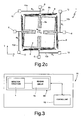
- FIGS. 2a-2c illustrate possible deformations thereof in response to different external stresses, and in particular in response to: a first, linear, acceleration acting along the first axis x ( Figure 2a ); a second, linear, acceleration acting along the second axis y ( Figure 2b ); and a third, angular, acceleration acting about the centroidal axis, or, in an equivalent way, about the third axis z.
- the arrangement of the elastic elements 8 enables in fact three movements of the inertial mass 2 in the plane xy (a first translation and a second translation, respectively along the first axis x and the second axis y, and moreover a rotation about the third axis z); the effects of said movements on the resonant elements 10a-10d can be decoupled in such a way as to enable detection of the corresponding components of acceleration individually and without mutual interference.
- the four resonant elements 10a-10d have the same nominal frequency of resonance f 0 , as a result of the interaction with the corresponding first electrodes 13 and the associated electronic circuit.
- the inertial mass 2 When the inertial mass 2 is subjected to a first acceleration a x along the first axis x (in the direction of the arrow in Figure 2a ), the inertial mass 2 translates as a whole along said first axis x, as a result of the bending of the second (folded) portion 8b of a first pair of the elastic elements 8, and moreover of the bending of the first (linear) portion 8a of the remaining elastic elements 8 (in general, there occurs the bending of the springs with extension transverse to the direction of displacement, in this case with extension along the second axis y, whilst the springs with extension along the first axis x do not undergo an appreciable axial deformation).
- the movement of translation of the inertial mass 2 along the first axis x consequently causes, evidently, an compressive stress - N 1 on a first resonant element 10a of the pair of resonant elements arranged along the first axis x, and a tensile stress N 1 , having the same intensity, on the second resonant element 10c of said pair; in particular, the movement of the inertial mass 2 is transmitted to the resonant elements 10a, 10c by the respective elastic elements 8, at the point of connection c, the position of which is substantially constrained.
- the resonance frequency of the first resonant element 10a designated by f 1
- the resonance frequency of the second resonant element 10c of the pair designated by f 2
- the resonant elements 10b, 10d of the other pair of resonant elements arranged along the second axis y are, instead, substantially not loaded and not subject to axial stresses with respect to the resting condition, in the presence of said first external acceleration a x .
- a second acceleration a y acting along the second axis y determines an overall displacement of the inertial mass 2 along the second axis y (in the direction indicated by the arrow in Figure 2b ).
- the movement of translation of the inertial mass 2 along the second axis y causes in this case a compressive stress - N 2 (with N 2 that can be equal to N 1 , in the case of a perfectly symmetrical structure) on a first resonant element 10d of the pair of resonant elements arranged along the second axis y, and a tensile stress N 2 , of the same intensity, on the second resonant element 10b of the pair.
- the difference between the resonance frequencies (f 4 -f 3 ) of said resonant elements 10d, 10b is hence proportional to the value of the second external acceleration a y acting along the second axis y, which can conveniently be measured by the electronic circuit coupled to the microelectromechanical detection structure 1.
- the resonant elements 10a, 10c of the other pair of resonant elements arranged along the first axis x are, instead, substantially not loaded and not subject to stresses with respect to the resting condition, in the presence of the second external acceleration a y .
- the microelectromechanical detection structure 1 is moreover sensitive to a third, angular, external acceleration a ⁇ acting about the third axis z, as illustrated in Figure 2c .
- the inertial mass 2 is set in rotation about its centroidal axis, causing axial stresses of the same value and sign, N ⁇ , in all four resonant elements 10a-10d.
- N ⁇ the same value and sign
- N ⁇ the same value and sign
- microelectromechanical detection structure 1 is configured in such a way as to decouple the effects of the external accelerations on the resonant elements 10a-10d, and in particular in such a way that it is possible, by means of appropriate combinations of the electrical quantities supplied by the various resonant elements 10a-10d, to determine independently the value of said external accelerations.
- the microelectromechanical detection structure 1 is conveniently coupled to an appropriate electronic reading circuit 15, configured in such a way as to carry out the aforesaid processing operations and combinations of the values of frequency f 1 -f 4 in order to determine the values of the linear external accelerations, a x and a y , and angular acceleration a ⁇ .
- the electronic reading circuit 15 comprises three measurement channels decoupled from one another, for the measurement one of the first linear acceleration a x , one of the second external linear acceleration a y , and one of the external angular acceleration a ⁇ ).
- the microelectromechanical detection structure 1 and the associated electronic reading circuit 15 form together a resonant biaxial accelerometer 16 (moreover able to detect an angular acceleration, as illustrated previously).
- the electronic reading circuit 15 is conveniently provided in an integrated form as ASIC (application-specific integrated circuit), in a die, which can be advantageously housed in the same package that houses also the die in which the microelectromechanical detection structure 1 is provided.
- ASIC application-specific integrated circuit
- a control unit 19 for example, a microprocessor control unit
- microelectromechanical detection structure 1' which differs from the one illustrated previously by a different configuration of its constitutive elements. Operation of the microelectromechanical detection structure 1' does not differ, instead, from what has been illustrated previously, and, for said reason, will not be described again in what follows.
- said second embodiment is distinguished by the fact that the resonant elements 10a-10d are set internally with respect to the encumbrance of the inertial mass, designated here by 2', in the plane xy.
- the inertial mass 2' comprises in this case a frame 20, for example having a substantially square perimeter in the plane xy, and defining inside an internal opening 22.
- the inertial mass 2' also comprises in this case four portions of mass, designated here by 2a'-2d', which are arranged inside the frame 20 in the internal opening 22 and are connected to respective internal corners of said frame 20.
- the portions of mass 2a'-2d' have, for example, a substantially rectangular shape in the plane xy and are arranged parallel in pairs and symmetrically with respect to the centre of gravity G.
- the inertial mass 2' is here fixed to the substrate (once again not illustrated) by means of a single first anchorage 6, set centrally in the internal opening 22, and traversed centrally by the centroidal axis (in a position corresponding to the centre of gravity G).
- the second portion 8b of each elastic element 8 is in particular set between the internal lateral surface of said frame 20 and a lateral surface of respective portions of mass 2a'-2d' of the inertial mass 2', facing it.
- the first portion 8a of each elastic element 8 has a length much smaller than that of the third portion 8c, given the central position of the single first anchorage 6 and the arrangement of the second portion 8b of said elastic elements 8.
- the resonant elements 10a-10d are arranged in the internal opening 22, inside the frame 20, facing the respective electrodes 13, 14, which are also arranged in said internal opening 22.
- the resonant elements 10a-10d, and the associated electrodes 13, 14, are set internally with respect to the portions of mass 2a'-2d' with respect to the frame 20, in the proximity of central axes of symmetry of the inertial mass 2' (parallel to the first axis x and to the second axis y).
- the resonant elements 10a-10d extend from a respective second anchorage 12 (the second anchorages 12 being four in number and being arranged in the internal opening 22), until they connect up to a respective elastic element 8, in particular to the third portion 8c of said elastic element 8.
- the point of connection c in which each resonant element 10a-10d is connected to the respective elastic element 8 is in this case in close proximity of the single first anchorage 6, set centrally with respect to the structure.
- Said second embodiment has the advantage of presenting a compact structure, all enclosed inside the frame 20 of the inertial mass 2'.
- the presence of a single first anchorage 6 for said inertial mass 2', set in a position corresponding to the centre of gravity G of the structure is advantageous for the reduction of the thermomechanical stresses possibly acting on the structure (for example, due to deformations of the package of the resonant biaxial accelerometer 16).
- Figures 5 and 6 are top plan views of the microelectromechanical detection structures 1, 1' described previously, respectively according to the first embodiment and the second embodiment, obtained by means of SEM. There may be noted the presence of holes made throughout the thickness of the inertial mass 2, 2', in order to enable release thereof with respect to the substrate by chemical etching of underlying regions of material, and moreover the presence of appropriate paths for electrical connection to the elements of the structure.
- designated by 30 is the substrate of the microelectromechanical detection structures 1, 1', made for example of silicon, and designated by 31 are the stopper elements arranged at the corners of the inertial mass 2, 2'.
- the microelectromechanical detection structure 1, 1' can be obtaining with surface-micromachining processes, for example using the so-called ThELMA (thick epipoly layer for microactuators and accelerometers) process.
- ThELMA thin epipoly layer for microactuators and accelerometers
- the ThELMA process enables fabrication of suspended structures of relatively large thicknesses (for example of the order of 10-15 ⁇ m), anchored to the substrate through compliant parts (springs) and consequently capable of displacing at least in a plane parallel to the underlying silicon substrate (the plane xy referred to above).
- the process consists of different production steps:
- the microelectromechanical detection structure 1, 1' combined with an appropriate electronic reading circuit 15, provides biaxial resonant accelerometers 16 of a very small size, smaller in particular than that of capacitive accelerometers obtained with the same technology.
- the reduction in size is obtained by using a single inertial mass 2, 2' for detection of two components of acceleration in the plane xy, and possibly, albeit with lower sensitivity, of a further angular acceleration, and moreover by means of an appropriate arrangement of the resonant elements 10a-10d with respect to said inertial mass 2, 2'.
- the structure proposed enables, for example, with dimensions of approximately 550 ⁇ m x 550 ⁇ m, a sensitivity higher than 200 Hz/g to be obtained.
- the sensitivity for the angular acceleration is, instead, lower than the sensitivity for the linear accelerations in the plane xy, for example, in the region of 0.05 Hz/(rad/s 2 ).
- the structure proposed enables reduction of the effects of the spurious axial forces on the resonant beams, and moreover the differential measurement of frequency increases the range of linearity of the accelerometer.
- the presence of two resonant elements subjected to axial action of opposite sign for a given external linear acceleration enables measurement of acceleration even in the presence of a state of internal stress generated, for example, by a thermal variation.
- microelectromechanical detection structure 1, 1' could differ from the one described previously.
- the microelectromechanical detection structure 1, 1' could comprise a single resonant element 10a-10d for each axis of detection x, y.
- Figures 7a and 7b show further variants of the microelectromechanical detection structure 1, in which the resonant elements 10a-10d and the corresponding second anchorages 12, as also the first anchorages 6 of the inertial mass 2, are arranged externally with respect to the inertial mass 2, in the plane xy.
- a stopper element 31 is set centrally with respect to the inertial mass 2, within an opening made through said inertial mass 2, which otherwise is constituted by a single body of a generically square shape in plan view.
- the elastic elements 8, and in particular the corresponding second portions 8b, of a folded type are connected to projections 34 of the inertial mass 2 (which project with respect to the substantially square overall dimensions of said inertial mass 2 in the plane xy).
- the elastic elements 8 can also in this case comprise first rectilinear portions 8a, set between respective second portions 8b and projections 34.
- the projections 34 which are four in number, are arranged centrally with respect to respective peripheral sides of the inertial mass 2, whilst in the variant of Figure 7b the projections 34 are arranged at the corners of the inertial mass 2.
- the third portions 8c, of a rectilinear type, of said elastic elements 8 extend once again in a direction transverse to the respective resonant elements 10a-10d, connecting up to the respective first anchorages 6 of the inertial mass 2 (which are here again four in number).
- the resonant elements 10a-10d are connected to the elastic elements 8, at a point of connection c of the corresponding third portion 8c, close to the corresponding first anchorage 6.
- the second portions 8b of elastic elements 8 associated to resonant elements 10a-10d that do not belong to said pair are moreover arranged parallel and adjacent to peripheral opposite sides, facing one another, of the inertial mass 2.
Landscapes
- Physics & Mathematics (AREA)
- General Physics & Mathematics (AREA)
- Micromachines (AREA)
- Pressure Sensors (AREA)
- Gyroscopes (AREA)
- Steroid Compounds (AREA)
Claims (12)
- Microstructure électromécanique de détection (1 ; 1') pour un accéléromètre biaxial résonnant MEMS (16), comprenant :- une masse inertielle (2 ; 2') ancrée à un substrat (30) au moyen d'éléments élastiques (8) afin d'être suspendue au-dessus dudit substrat (30), lesdits éléments élastiques (8) étant structurés pour permettre des mouvements inertiels de détection de ladite masse inertielle (2 ; 2') le long d'un premier axe de détection (x) et d'un second axe de détection (y) appartenant à un plan (xy) d'extension principale de ladite masse inertielle (2 ; 2'), sensible aux accélérations externes linéaires (ax, ay) respectives ; etau moins un premier élément résonnant (10a) et un deuxième élément résonnant (10b), ayant une extension longitudinale respective, respectivement le long dudit premier axe de détection (x) et dudit second axe de détection (y), et mécaniquement couplée à ladite masse inertielle (2 ; 2') par le biais d'un élément respectif desdits éléments élastiques (8), afin de subir une sollicitation axiale (N1, N2) respective lorsque ladite masse inertielle se déplace respectivement le long dudit premier axe de détection (x) et le long dudit second axe de détection (y) ;
dans laquelle chacun desdits éléments élastiques (8) s'étend à partir d'un premier ancrage (6) de ladite masse inertielle (2 ; 2') audit substrat (30), jusqu'à ladite masse inertielle (2 ; 2') ; et dans laquelle chacun desdits premier (10a) et deuxième (10b) éléments résonnants est ancré audit substrat (30) au niveau de sa première extrémité, au moyen d'un second ancrage (12) respectif, et est de plus, mécaniquement couplé à l'élément respectif desdits éléments élastiques (8) au niveau de sa seconde extrémité, à un point de raccordement (c) de l'élément respectif desdits éléments élastiques (8) ; dans laquelle ledit point de raccordement (c) est positionné le long dudit élément respectif desdits éléments élastiques (8), à une distance par rapport au premier ancrage (6) correspondant comprise entre 1/100 et 2/100 d'une longueur (L) dudit élément respectif des éléments élastiques (8) dans une direction transversale par rapport à ladite extension longitudinale du premier (10a) ou deuxième (10b) élément résonnant associé ; et dans laquelle chacun desdits éléments élastiques (8) comprend : une partie rectiligne (8c) s'étendant à partir du premier ancrage (6) dans une direction transversale par rapport à ladite extension longitudinale du premier (10a) ou deuxième (10b) élément résonnant associé, et une partie pliée (8b) qui est couplée mécaniquement et s'étend dans une direction transversale par rapport à ladite partie rectiligne (8c) ; ladite partie rectiligne (8c) étant couplée au premier (10a) ou deuxième (10b) élément résonnant associé au niveau dudit point de raccordement (c). - Structure selon l'une quelconque des revendications précédentes, dans laquelle ladite partie rectiligne (8c) est configurée pour se plier afin de permettre sa sollicitation axiale (N1, N2) lorsque ladite masse inertielle se déplace le long dudit premier (x) ou second (y) axe de détection, respectivement, c'est-à-dire dans une direction parallèle à l'extension longitudinale du premier (10a) ou deuxième (10b) élément résonnant associé ; et ladite partie pliée (8b) est configurée pour subir la déformation lorsque ladite masse inertielle se déplace le long dudit second (y) ou premier (x) axe de détection, respectivement, c'est-à-dire dans une direction transversale par rapport à l'extension longitudinale du premier (10a) ou deuxième (10b) élément résonnant associé.
- Structure selon la revendication 1 ou 2, dans laquelle ladite partie pliée (8b) comprend une pluralité de segments rectilignes, parallèles entre eux et assemblés au niveau des extrémités respectives ; et dans laquelle ladite partie rectiligne (8c) a une première extrémité raccordée au premier ancrage (6) correspondant et une seconde extrémité raccordée à un segment rectiligne terminal de ladite partie pliée (8b) ; chacun desdits éléments élastiques (8) comprenant une autre partie rectiligne (8a) ayant une première extrémité raccordée à ladite masse inertielle (2 ; 2') et une seconde extrémité raccordée à un segment rectiligne initial de ladite partie pliée (8b).
- Structure selon l'une quelconque des revendications précédentes, comprenant en outre un troisième (10c) et un quatrième (10d) élément résonnant, ayant une extension longitudinale respectivement, le long desdits premier (x) et second (y) axes de détection, dans une direction parallèle, respectivement auxdits premier (10a) et deuxième (10b) éléments résonnants et mécaniquement couplés à ladite masse inertielle (2 ; 2') par le biais d'éléments respectifs desdits éléments élastiques (8), afin de subir une sollicitation axiale (N1, N2) respective de la même intensité et de signe opposé par rapport à la sollicitation axiale desdits premier (10a) et deuxième (10b) éléments résonnants, respectivement, lorsque ladite masse inertielle se déplace le long desdits premier (x) et second (y) axes de détection, respectivement.
- Structure selon l'une quelconque des revendications précédentes, dans laquelle lesdits premier (10a) et deuxième (10b) éléments résonnants sont agencés à l'extérieur de ladite masse inertielle (2) par rapport audit plan (xy) ; et dans laquelle ladite masse inertielle (2) a une partie centrale (2e) et des parties latérales (2a-2d), qui sont raccordées par ladite partie centrale (2e) et définissent entre elles des fenêtres (4) qui s'ouvrent vers l'extérieur de ladite masse inertielle (2) ; et dans laquelle lesdits éléments élastiques (8) s'étendent à partir de ladite partie centrale (2e), en partie à travers lesdites fenêtres (4) afin d'atteindre les premiers ancrages (6) respectifs de ladite masse inertielle (2) jusqu'audit substrat (30), qui sont placées à l'extérieur de ladite masse inertielle (2) par rapport audit plan (xy).
- Structure selon l'une quelconque des revendications précédentes, dans laquelle lesdits premier (10a) et deuxième (10b) éléments résonnants sont agencés à l'extérieur de ladite masse inertielle (2) par rapport audit plan (xy), et ladite masse inertielle (2) a des saillies (34) qui s'étendent dans ledit plan (xy) à partir des côtés périphériques de ladite masse inertielle ; lesdits éléments élastiques (8) s'étendant à partir des saillies (34) respectives jusqu'à ce qu'ils atteignent des premiers ancrages (6) respectifs de ladite masse inertielle (2) jusqu'audit substrat (30), lesdits premiers ancrages (6) étant agencés à l'extérieur de ladite masse inertielle (2) par rapport audit plan (xy) ; et dans laquelle ladite partie pliée (8b) s'étend de manière adjacente à un premier côté desdits côtés périphériques de ladite masse inertielle (2), et ledit premier (10a) ou deuxième (10b) élément résonnant associé s'étend de manière adjacente à un second côté desdits côtés périphériques, parallèlement et faisant face audit second côté périphérique.
- Structure selon l'une quelconque des revendications 1 à 4, dans laquelle ladite masse inertielle (2') comprend un châssis (20) définissant à l'intérieur de ce dernier une ouverture interne (22), et lesdits éléments élastiques (8) s'étendent entièrement dans ladite ouverture interne (22) à partir dudit châssis (20) jusqu'à ce qu'ils atteignent un premier ancrage (6) unique de ladite masse inertielle (2') jusqu'audit substrat (30), ledit premier ancrage (6) unique étant agencé de manière centrale par rapport à ladite ouverture interne (22) ; et dans laquelle lesdits premier (10a) et deuxième (10b) éléments résonnants sont placés à l'intérieur de ladite mase inertielle (2) par rapport audit plan (xy), dans ladite ouverture interne (22).
- Structure selon l'une quelconque des revendications précédentes, dans laquelle lesdits éléments élastiques (8) sont configurés pour permettre un autre mouvement inertiel de détection de ladite masse inertielle (2 ; 2'), c'est-à-dire une rotation autour d'un axe (z) orthogonal audit plan (xy), en réponse à un accélération angulaire externe (aθ) ; et dans laquelle lesdits premier (10a) et deuxième (10b) éléments résonnants sont mécaniquement couplés à ladite masse inertielle (2 ; 2') par le biais d'un élément respectif desdits éléments élastiques (8) afin de subir la même sollicitation axiale (Ne), lorsque ladite masse inertielle se déplace selon ledit mouvement de détection inertiel supplémentaire.
- Structure selon l'une quelconque des revendications précédentes, comprenant en outre des premières électrodes (13), électriquement couplées auxdits premier (10a) et deuxième (10b) éléments résonnants pour permettre la génération de leur état de résonnance ; et des secondes électrodes (14), électriquement couplées auxdits premier (10a) et deuxième (10b) éléments résonnants pour permettre la détection d'une variation respective d'une fréquence de résonnance (f1, f2), en fonction de ladite sollicitation axiale (N1, N2) respective.
- Accéléromètre biaxial résonnant (16) comprenant une microstructure électromécanique de détection (1 ; 1') selon l'une quelconque des revendications précédentes, et configuré pour détecter un premier (ax) et un second (ay) composant d'accélération externe linéaire, dirigés respectivement, le long desdits premier (x) et second (y) axes de détection.
- Accéléromètre selon la revendication 10, comprenant en outre un circuit de lecture (15) couplé électriquement à ladite microstructure électromagnétique de détection (1 ; 1').
- Appareil électronique (18), comprenant un accéléromètre biaxial résonnant (16) selon la revendication 10 ou 11, et une unité de commande (19) électriquement raccordée audit circuit de lecture (15).
Applications Claiming Priority (2)
| Application Number | Priority Date | Filing Date | Title |
|---|---|---|---|
| ITTO2010A000944A IT1405796B1 (it) | 2010-11-26 | 2010-11-26 | Struttura di accelerometro biassiale risonante di tipo microelettromeccanico |
| PCT/IB2011/055309 WO2012070021A1 (fr) | 2010-11-26 | 2011-11-25 | Structure d'accéléromètre bi-axial résonant du type micro-électromécanique |
Publications (2)
| Publication Number | Publication Date |
|---|---|
| EP2643702A1 EP2643702A1 (fr) | 2013-10-02 |
| EP2643702B1 true EP2643702B1 (fr) | 2015-08-05 |
Family
ID=43743107
Family Applications (1)
| Application Number | Title | Priority Date | Filing Date |
|---|---|---|---|
| EP11799844.3A Active EP2643702B1 (fr) | 2010-11-26 | 2011-11-25 | Structure d'accéléromètre bi-axial résonant du type micro-électromécanique |
Country Status (5)
| Country | Link |
|---|---|
| US (1) | US8671756B2 (fr) |
| EP (1) | EP2643702B1 (fr) |
| CN (1) | CN103250057B (fr) |
| IT (1) | IT1405796B1 (fr) |
| WO (1) | WO2012070021A1 (fr) |
Families Citing this family (39)
| Publication number | Priority date | Publication date | Assignee | Title |
|---|---|---|---|---|
| WO2007147137A2 (fr) | 2006-06-15 | 2007-12-21 | Sitime Corporation | Boîtier de puces empilées pour un système résonateur de mems |
| IT1395419B1 (it) * | 2009-09-07 | 2012-09-14 | Milano Politecnico | Accelerometro risonante mems con migliorate caretteristiche elettriche |
| GB201009062D0 (en) * | 2010-05-28 | 2010-07-14 | Cambridge Entpr Ltd | MEMS inertial sensor and method of inertial sensing |
| US9695036B1 (en) | 2012-02-02 | 2017-07-04 | Sitime Corporation | Temperature insensitive resonant elements and oscillators and methods of designing and manufacturing same |
| US8916407B1 (en) | 2012-03-29 | 2014-12-23 | Sitime Corporation | MEMS device and method of manufacturing same |
| ITTO20120691A1 (it) | 2012-08-01 | 2014-02-02 | Milano Politecnico | Sensore d'urto con meccanismo bistabile e metodo per il rilevamento di urti |
| GB2505875A (en) * | 2012-09-04 | 2014-03-19 | Cambridge Entpr Ltd | Dual and triple axis inertial sensors and methods of inertial sensing |
| JP6020392B2 (ja) | 2013-09-03 | 2016-11-02 | 株式会社デンソー | 加速度センサ |
| CN103454449A (zh) * | 2013-09-15 | 2013-12-18 | 滕金燕 | 一种三轴微机械加速度计 |
| US9705470B1 (en) | 2014-02-09 | 2017-07-11 | Sitime Corporation | Temperature-engineered MEMS resonator |
| US9712128B2 (en) | 2014-02-09 | 2017-07-18 | Sitime Corporation | Microelectromechanical resonator |
| US11674803B2 (en) | 2014-06-02 | 2023-06-13 | Motion Engine, Inc. | Multi-mass MEMS motion sensor |
| US9581614B2 (en) | 2014-06-02 | 2017-02-28 | Meggit (Orange County), Inc. | High-output MEMS accelerometer |
| US9625486B2 (en) | 2014-07-17 | 2017-04-18 | Meggitt (Orange County), Inc. | MEMS accelerometer |
| US9689888B2 (en) * | 2014-11-14 | 2017-06-27 | Honeywell International Inc. | In-plane vibrating beam accelerometer |
| US10823754B2 (en) | 2014-11-14 | 2020-11-03 | Honeywell International Inc. | Accelerometer with strain compensation |
| CN104865406A (zh) * | 2015-03-27 | 2015-08-26 | 东南大学 | 基于杠杆放大原理的双轴全解耦硅微谐振式加速度计 |
| EP3136052B1 (fr) * | 2015-08-31 | 2021-03-24 | Commissariat à l'Énergie Atomique et aux Énergies Alternatives | Dispositif de résonance de détection piézorésistive en particulier avec une grande amplitude de vibrations |
| US10545167B2 (en) | 2015-10-20 | 2020-01-28 | Analog Devices, Inc. | Multiple-axis resonant accelerometers |
| ITUA20162173A1 (it) | 2016-03-31 | 2017-10-01 | St Microelectronics Srl | Sensore accelerometrico mems avente elevata accuratezza e ridotta sensibilita' nei confronti della temperatura e dell'invecchiamento |
| US10676349B1 (en) | 2016-08-12 | 2020-06-09 | Sitime Corporation | MEMS resonator |
| CN106771358A (zh) * | 2016-11-30 | 2017-05-31 | 西安交通大学 | 一种微型差动式全石英谐振加速度计 |
| CN106597011B (zh) * | 2016-12-23 | 2018-11-23 | 中北大学 | 双轴mems谐振式加速度传感器结构 |
| CN108092638B (zh) * | 2017-11-27 | 2021-03-19 | 东南大学 | 一种三角形折叠梁质量块谐振系统、检测方法及制作工艺 |
| CN108225544B (zh) * | 2017-11-27 | 2020-02-18 | 东南大学 | 一种双层复用型三角形折叠梁质量块谐振系统及其痕量检测方法 |
| RU180986U1 (ru) * | 2018-03-05 | 2018-07-03 | Общество с ограниченной ответственностью "Лаборатория Микроприборов" (ООО "ЛМП) | Виброчастотный датчик линейных ускорений |
| US10895457B2 (en) | 2018-03-08 | 2021-01-19 | Analog Devices, Inc. | Differential z-axis resonant accelerometry |
| US11275099B1 (en) * | 2018-07-20 | 2022-03-15 | Hrl Laboratories, Llc | Navigational grade resonant MicroElectroMechanical Systems (mems) accelerometer and method of operation |
| RU190397U1 (ru) * | 2018-08-13 | 2019-07-01 | Акционерное общество "ГИРООПТИКА" (АО "ГИРООПТИКА") | Микромеханический осевой акселерометр |
| US10816569B2 (en) | 2018-09-07 | 2020-10-27 | Analog Devices, Inc. | Z axis accelerometer using variable vertical gaps |
| US11255873B2 (en) | 2018-09-12 | 2022-02-22 | Analog Devices, Inc. | Increased sensitivity z-axis accelerometer |
| JP6870761B2 (ja) | 2019-05-15 | 2021-05-12 | 株式会社村田製作所 | ロバストなz軸加速度センサ |
| US10823569B1 (en) | 2019-08-22 | 2020-11-03 | Nxp Usa, Inc. | Multiple axis sensing device based on frequency modulation and method of operation |
| US11377346B2 (en) * | 2019-09-11 | 2022-07-05 | Murata Manufacturing Co., Ltd. | Low-noise multi axis MEMS accelerometer |
| EP3792637B1 (fr) | 2019-09-11 | 2023-05-03 | Murata Manufacturing Co., Ltd. | Accéléromètre mems à faible bruit à axes multiples |
| IT202000018670A1 (it) * | 2020-07-30 | 2022-01-30 | St Microelectronics Srl | Accelerometro mems a larga banda per la rilevazione di vibrazioni |
| IT202100014183A1 (it) * | 2021-05-31 | 2022-12-01 | St Microelectronics Srl | Attuatore mems per movimento in piano di una massa mobile e modulo ottico comprendente l'attuatore mems |
| IT202100023795A1 (it) | 2021-09-15 | 2023-03-15 | St Microelectronics Srl | Accelerometro risonante ad asse z con struttura di rilevamento avente prestazioni migliorate |
| CN120629631A (zh) * | 2025-06-06 | 2025-09-12 | 华中科技大学 | 探测微振动的微型面外加速度传感器和加速度探测方法 |
Family Cites Families (20)
| Publication number | Priority date | Publication date | Assignee | Title |
|---|---|---|---|---|
| US4851080A (en) * | 1987-06-29 | 1989-07-25 | Massachusetts Institute Of Technology | Resonant accelerometer |
| FR2667157B1 (fr) | 1990-09-25 | 1994-06-10 | Sextant Avionique | Micro-accelerometre a resonateurs et procede de fabrication. |
| FR2720509B1 (fr) | 1994-05-27 | 1996-08-23 | Sextant Avionique | Microaccéléromètre à résonateur compensé en température. |
| FR2723638B1 (fr) | 1994-08-10 | 1996-10-18 | Sagem | Transducteur force-frequence a poutres vibrantes |
| US5894090A (en) * | 1996-05-31 | 1999-04-13 | California Institute Of Technology | Silicon bulk micromachined, symmetric, degenerate vibratorygyroscope, accelerometer and sensor and method for using the same |
| US5969249A (en) | 1997-05-07 | 1999-10-19 | The Regents Of The University Of California | Resonant accelerometer with flexural lever leverage system |
| US5948982A (en) | 1998-02-23 | 1999-09-07 | Alliedsignal Inc. | Vibrating beam accelerometers and methods of forming vibrating beam accelerometers |
| DE19812773C2 (de) * | 1998-03-24 | 2002-11-14 | Conti Temic Microelectronic | Mikrosensor mit einer Resonatorstruktur |
| FR2784752B1 (fr) | 1998-10-20 | 2000-11-17 | Onera (Off Nat Aerospatiale) | Accelerometre miniature monolithique |
| JP2001174264A (ja) | 1999-12-21 | 2001-06-29 | Murata Mfg Co Ltd | 共振素子およびその振動調整方法 |
| US6662655B2 (en) | 2000-10-31 | 2003-12-16 | Honeywell International, Inc. | Net zero isolator |
| EP1352252A2 (fr) | 2001-01-17 | 2003-10-15 | Honeywell International Inc. | Accelerometre de palonnier |
| FR2821434B1 (fr) | 2001-02-26 | 2003-07-04 | Sagem | Accelerometre miniature a deux cellules |
| DE60213981T2 (de) | 2001-05-15 | 2007-08-30 | Honeywell International Inc. | Element zur spannungsentlastung für einen beschleunigungssensor |
| US6651500B2 (en) | 2001-10-03 | 2003-11-25 | Litton Systems, Inc. | Micromachined silicon tuned counterbalanced accelerometer-gyro with quadrature nulling |
| FR2848298B1 (fr) * | 2002-12-10 | 2005-03-11 | Thales Sa | Accelerometre a poutre vibrante |
| FR2862761B1 (fr) | 2003-11-25 | 2006-02-03 | Thales Sa | Accelerometre differentiel micro-usine multiaxes |
| FR2906038B1 (fr) | 2006-09-19 | 2008-11-28 | Commissariat Energie Atomique | Accelerometre a poutre resonante avec bras de levier articule en rotation |
| WO2009048621A1 (fr) * | 2007-10-11 | 2009-04-16 | Georgia Tech Research Corporation | Accéléromètres à ondes acoustiques de volume |
| IT1395419B1 (it) | 2009-09-07 | 2012-09-14 | Milano Politecnico | Accelerometro risonante mems con migliorate caretteristiche elettriche |
-
2010
- 2010-11-26 IT ITTO2010A000944A patent/IT1405796B1/it active
-
2011
- 2011-11-22 US US13/303,038 patent/US8671756B2/en active Active
- 2011-11-25 EP EP11799844.3A patent/EP2643702B1/fr active Active
- 2011-11-25 WO PCT/IB2011/055309 patent/WO2012070021A1/fr not_active Ceased
- 2011-11-25 CN CN201180058118.4A patent/CN103250057B/zh active Active
Also Published As
| Publication number | Publication date |
|---|---|
| US20120132003A1 (en) | 2012-05-31 |
| IT1405796B1 (it) | 2014-01-24 |
| EP2643702A1 (fr) | 2013-10-02 |
| US8671756B2 (en) | 2014-03-18 |
| CN103250057A (zh) | 2013-08-14 |
| ITTO20100944A1 (it) | 2012-05-27 |
| WO2012070021A1 (fr) | 2012-05-31 |
| CN103250057B (zh) | 2016-04-27 |
Similar Documents
| Publication | Publication Date | Title |
|---|---|---|
| EP2643702B1 (fr) | Structure d'accéléromètre bi-axial résonant du type micro-électromécanique | |
| US8516889B2 (en) | MEMS resonant accelerometer having improved electrical characteristics | |
| EP2893362B1 (fr) | Capteurs inertiels à double et triple axe et procédés de détection inertielle | |
| US6634231B2 (en) | Accelerometer strain isolator | |
| US6662658B2 (en) | Whiffletree accelerometer | |
| US9389077B2 (en) | Acceleration and angular velocity resonant detection integrated structure, and related MEMS sensor device | |
| US8616059B2 (en) | Force sensor with reduced noise | |
| CN103827673B (zh) | 用于z轴谐振加速度计的改进检测结构 | |
| US8297121B2 (en) | Micro-machined accelerometer | |
| CN101858927A (zh) | 低应力硅微谐振式加速度计 | |
| Li et al. | Design and sensitivity analysis of a micro-resonant accelerometer with adjustable stiffness | |
| Li et al. | A micro-machined differential resonance accelerometer based on silicon on quartz method | |
| CN201673168U (zh) | 低应力硅微谐振式加速度计 | |
| Tabata et al. | Two-axis detection resonant accelerometer based on rigidity change | |
| EP1166129B1 (fr) | Capteur de force a lame vibrante | |
| Hou et al. | A double differential torsional accelerometer with higher than 10-kHz measurement bandwidth for vibration monitoring | |
| JP2009092396A (ja) | 振動式センサ | |
| EP2201387B1 (fr) | Pivot à lames flexibles pour micro-capteurs | |
| JP2008309731A (ja) | 加速度検知ユニット及び加速度センサ | |
| Li et al. | A resonant accelerometer based on piezoelectric TBTF MEMS resonator and two-stage microleverage | |
| HaLevy et al. | Compliant parallel motion linkage amplification mechanism for resonant force/acceleration sensing | |
| Li et al. | A micro resonant acceleration sensor comprising silicon support with temperature isolator and quartz doubled ended tuning fork | |
| Chen et al. | Design of an accelerometer in inclination monitoring of power transmission pole |
Legal Events
| Date | Code | Title | Description |
|---|---|---|---|
| PUAI | Public reference made under article 153(3) epc to a published international application that has entered the european phase |
Free format text: ORIGINAL CODE: 0009012 |
|
| 17P | Request for examination filed |
Effective date: 20130524 |
|
| AK | Designated contracting states |
Kind code of ref document: A1 Designated state(s): AL AT BE BG CH CY CZ DE DK EE ES FI FR GB GR HR HU IE IS IT LI LT LU LV MC MK MT NL NO PL PT RO RS SE SI SK SM TR |
|
| DAX | Request for extension of the european patent (deleted) | ||
| 17Q | First examination report despatched |
Effective date: 20140725 |
|
| GRAP | Despatch of communication of intention to grant a patent |
Free format text: ORIGINAL CODE: EPIDOSNIGR1 |
|
| RIC1 | Information provided on ipc code assigned before grant |
Ipc: G01P 15/18 20130101ALI20150209BHEP Ipc: G01P 15/08 20060101ALI20150209BHEP Ipc: G01P 15/097 20060101AFI20150209BHEP |
|
| INTG | Intention to grant announced |
Effective date: 20150224 |
|
| GRAS | Grant fee paid |
Free format text: ORIGINAL CODE: EPIDOSNIGR3 |
|
| GRAA | (expected) grant |
Free format text: ORIGINAL CODE: 0009210 |
|
| AK | Designated contracting states |
Kind code of ref document: B1 Designated state(s): AL AT BE BG CH CY CZ DE DK EE ES FI FR GB GR HR HU IE IS IT LI LT LU LV MC MK MT NL NO PL PT RO RS SE SI SK SM TR |
|
| REG | Reference to a national code |
Ref country code: GB Ref legal event code: FG4D |
|
| REG | Reference to a national code |
Ref country code: CH Ref legal event code: EP |
|
| REG | Reference to a national code |
Ref country code: AT Ref legal event code: REF Ref document number: 741010 Country of ref document: AT Kind code of ref document: T Effective date: 20150815 |
|
| REG | Reference to a national code |
Ref country code: IE Ref legal event code: FG4D |
|
| REG | Reference to a national code |
Ref country code: DE Ref legal event code: R096 Ref document number: 602011018537 Country of ref document: DE |
|
| REG | Reference to a national code |
Ref country code: AT Ref legal event code: MK05 Ref document number: 741010 Country of ref document: AT Kind code of ref document: T Effective date: 20150805 |
|
| REG | Reference to a national code |
Ref country code: LT Ref legal event code: MG4D |
|
| REG | Reference to a national code |
Ref country code: NL Ref legal event code: MP Effective date: 20150805 |
|
| PG25 | Lapsed in a contracting state [announced via postgrant information from national office to epo] |
Ref country code: LV Free format text: LAPSE BECAUSE OF FAILURE TO SUBMIT A TRANSLATION OF THE DESCRIPTION OR TO PAY THE FEE WITHIN THE PRESCRIBED TIME-LIMIT Effective date: 20150805 Ref country code: NO Free format text: LAPSE BECAUSE OF FAILURE TO SUBMIT A TRANSLATION OF THE DESCRIPTION OR TO PAY THE FEE WITHIN THE PRESCRIBED TIME-LIMIT Effective date: 20151105 Ref country code: FI Free format text: LAPSE BECAUSE OF FAILURE TO SUBMIT A TRANSLATION OF THE DESCRIPTION OR TO PAY THE FEE WITHIN THE PRESCRIBED TIME-LIMIT Effective date: 20150805 Ref country code: LT Free format text: LAPSE BECAUSE OF FAILURE TO SUBMIT A TRANSLATION OF THE DESCRIPTION OR TO PAY THE FEE WITHIN THE PRESCRIBED TIME-LIMIT Effective date: 20150805 Ref country code: GR Free format text: LAPSE BECAUSE OF FAILURE TO SUBMIT A TRANSLATION OF THE DESCRIPTION OR TO PAY THE FEE WITHIN THE PRESCRIBED TIME-LIMIT Effective date: 20151106 |
|
| PG25 | Lapsed in a contracting state [announced via postgrant information from national office to epo] |
Ref country code: PT Free format text: LAPSE BECAUSE OF FAILURE TO SUBMIT A TRANSLATION OF THE DESCRIPTION OR TO PAY THE FEE WITHIN THE PRESCRIBED TIME-LIMIT Effective date: 20151207 Ref country code: AT Free format text: LAPSE BECAUSE OF FAILURE TO SUBMIT A TRANSLATION OF THE DESCRIPTION OR TO PAY THE FEE WITHIN THE PRESCRIBED TIME-LIMIT Effective date: 20150805 Ref country code: RS Free format text: LAPSE BECAUSE OF FAILURE TO SUBMIT A TRANSLATION OF THE DESCRIPTION OR TO PAY THE FEE WITHIN THE PRESCRIBED TIME-LIMIT Effective date: 20150805 Ref country code: HR Free format text: LAPSE BECAUSE OF FAILURE TO SUBMIT A TRANSLATION OF THE DESCRIPTION OR TO PAY THE FEE WITHIN THE PRESCRIBED TIME-LIMIT Effective date: 20150805 Ref country code: IS Free format text: LAPSE BECAUSE OF FAILURE TO SUBMIT A TRANSLATION OF THE DESCRIPTION OR TO PAY THE FEE WITHIN THE PRESCRIBED TIME-LIMIT Effective date: 20151205 Ref country code: ES Free format text: LAPSE BECAUSE OF FAILURE TO SUBMIT A TRANSLATION OF THE DESCRIPTION OR TO PAY THE FEE WITHIN THE PRESCRIBED TIME-LIMIT Effective date: 20150805 Ref country code: PL Free format text: LAPSE BECAUSE OF FAILURE TO SUBMIT A TRANSLATION OF THE DESCRIPTION OR TO PAY THE FEE WITHIN THE PRESCRIBED TIME-LIMIT Effective date: 20150805 Ref country code: SE Free format text: LAPSE BECAUSE OF FAILURE TO SUBMIT A TRANSLATION OF THE DESCRIPTION OR TO PAY THE FEE WITHIN THE PRESCRIBED TIME-LIMIT Effective date: 20150805 |
|
| PG25 | Lapsed in a contracting state [announced via postgrant information from national office to epo] |
Ref country code: NL Free format text: LAPSE BECAUSE OF FAILURE TO SUBMIT A TRANSLATION OF THE DESCRIPTION OR TO PAY THE FEE WITHIN THE PRESCRIBED TIME-LIMIT Effective date: 20150805 |
|
| PG25 | Lapsed in a contracting state [announced via postgrant information from national office to epo] |
Ref country code: DK Free format text: LAPSE BECAUSE OF FAILURE TO SUBMIT A TRANSLATION OF THE DESCRIPTION OR TO PAY THE FEE WITHIN THE PRESCRIBED TIME-LIMIT Effective date: 20150805 Ref country code: SK Free format text: LAPSE BECAUSE OF FAILURE TO SUBMIT A TRANSLATION OF THE DESCRIPTION OR TO PAY THE FEE WITHIN THE PRESCRIBED TIME-LIMIT Effective date: 20150805 Ref country code: EE Free format text: LAPSE BECAUSE OF FAILURE TO SUBMIT A TRANSLATION OF THE DESCRIPTION OR TO PAY THE FEE WITHIN THE PRESCRIBED TIME-LIMIT Effective date: 20150805 Ref country code: CZ Free format text: LAPSE BECAUSE OF FAILURE TO SUBMIT A TRANSLATION OF THE DESCRIPTION OR TO PAY THE FEE WITHIN THE PRESCRIBED TIME-LIMIT Effective date: 20150805 Ref country code: IT Free format text: LAPSE BECAUSE OF FAILURE TO SUBMIT A TRANSLATION OF THE DESCRIPTION OR TO PAY THE FEE WITHIN THE PRESCRIBED TIME-LIMIT Effective date: 20150805 |
|
| REG | Reference to a national code |
Ref country code: DE Ref legal event code: R097 Ref document number: 602011018537 Country of ref document: DE |
|
| PG25 | Lapsed in a contracting state [announced via postgrant information from national office to epo] |
Ref country code: RO Free format text: LAPSE BECAUSE OF FAILURE TO SUBMIT A TRANSLATION OF THE DESCRIPTION OR TO PAY THE FEE WITHIN THE PRESCRIBED TIME-LIMIT Effective date: 20150805 |
|
| PLBE | No opposition filed within time limit |
Free format text: ORIGINAL CODE: 0009261 |
|
| STAA | Information on the status of an ep patent application or granted ep patent |
Free format text: STATUS: NO OPPOSITION FILED WITHIN TIME LIMIT |
|
| PG25 | Lapsed in a contracting state [announced via postgrant information from national office to epo] |
Ref country code: LU Free format text: LAPSE BECAUSE OF FAILURE TO SUBMIT A TRANSLATION OF THE DESCRIPTION OR TO PAY THE FEE WITHIN THE PRESCRIBED TIME-LIMIT Effective date: 20151125 Ref country code: MC Free format text: LAPSE BECAUSE OF FAILURE TO SUBMIT A TRANSLATION OF THE DESCRIPTION OR TO PAY THE FEE WITHIN THE PRESCRIBED TIME-LIMIT Effective date: 20150805 |
|
| REG | Reference to a national code |
Ref country code: CH Ref legal event code: PL |
|
| 26N | No opposition filed |
Effective date: 20160509 |
|
| GBPC | Gb: european patent ceased through non-payment of renewal fee |
Effective date: 20151125 |
|
| PG25 | Lapsed in a contracting state [announced via postgrant information from national office to epo] |
Ref country code: CH Free format text: LAPSE BECAUSE OF NON-PAYMENT OF DUE FEES Effective date: 20151130 Ref country code: LI Free format text: LAPSE BECAUSE OF NON-PAYMENT OF DUE FEES Effective date: 20151130 |
|
| REG | Reference to a national code |
Ref country code: IE Ref legal event code: MM4A |
|
| REG | Reference to a national code |
Ref country code: FR Ref legal event code: ST Effective date: 20160729 |
|
| PG25 | Lapsed in a contracting state [announced via postgrant information from national office to epo] |
Ref country code: SI Free format text: LAPSE BECAUSE OF FAILURE TO SUBMIT A TRANSLATION OF THE DESCRIPTION OR TO PAY THE FEE WITHIN THE PRESCRIBED TIME-LIMIT Effective date: 20150805 |
|
| PG25 | Lapsed in a contracting state [announced via postgrant information from national office to epo] |
Ref country code: GB Free format text: LAPSE BECAUSE OF NON-PAYMENT OF DUE FEES Effective date: 20151125 Ref country code: IE Free format text: LAPSE BECAUSE OF NON-PAYMENT OF DUE FEES Effective date: 20151125 |
|
| PG25 | Lapsed in a contracting state [announced via postgrant information from national office to epo] |
Ref country code: FR Free format text: LAPSE BECAUSE OF NON-PAYMENT OF DUE FEES Effective date: 20151130 |
|
| PG25 | Lapsed in a contracting state [announced via postgrant information from national office to epo] |
Ref country code: BE Free format text: LAPSE BECAUSE OF FAILURE TO SUBMIT A TRANSLATION OF THE DESCRIPTION OR TO PAY THE FEE WITHIN THE PRESCRIBED TIME-LIMIT Effective date: 20150805 |
|
| PG25 | Lapsed in a contracting state [announced via postgrant information from national office to epo] |
Ref country code: HU Free format text: LAPSE BECAUSE OF FAILURE TO SUBMIT A TRANSLATION OF THE DESCRIPTION OR TO PAY THE FEE WITHIN THE PRESCRIBED TIME-LIMIT; INVALID AB INITIO Effective date: 20111125 Ref country code: SM Free format text: LAPSE BECAUSE OF FAILURE TO SUBMIT A TRANSLATION OF THE DESCRIPTION OR TO PAY THE FEE WITHIN THE PRESCRIBED TIME-LIMIT Effective date: 20150805 Ref country code: BG Free format text: LAPSE BECAUSE OF FAILURE TO SUBMIT A TRANSLATION OF THE DESCRIPTION OR TO PAY THE FEE WITHIN THE PRESCRIBED TIME-LIMIT Effective date: 20150805 |
|
| PG25 | Lapsed in a contracting state [announced via postgrant information from national office to epo] |
Ref country code: CY Free format text: LAPSE BECAUSE OF FAILURE TO SUBMIT A TRANSLATION OF THE DESCRIPTION OR TO PAY THE FEE WITHIN THE PRESCRIBED TIME-LIMIT Effective date: 20150805 |
|
| REG | Reference to a national code |
Ref country code: DE Ref legal event code: R082 Ref document number: 602011018537 Country of ref document: DE Representative=s name: SCHMITT-NILSON SCHRAUD WAIBEL WOHLFROM PATENTA, DE |
|
| PG25 | Lapsed in a contracting state [announced via postgrant information from national office to epo] |
Ref country code: MT Free format text: LAPSE BECAUSE OF FAILURE TO SUBMIT A TRANSLATION OF THE DESCRIPTION OR TO PAY THE FEE WITHIN THE PRESCRIBED TIME-LIMIT Effective date: 20150805 |
|
| PG25 | Lapsed in a contracting state [announced via postgrant information from national office to epo] |
Ref country code: TR Free format text: LAPSE BECAUSE OF FAILURE TO SUBMIT A TRANSLATION OF THE DESCRIPTION OR TO PAY THE FEE WITHIN THE PRESCRIBED TIME-LIMIT Effective date: 20150805 Ref country code: MK Free format text: LAPSE BECAUSE OF FAILURE TO SUBMIT A TRANSLATION OF THE DESCRIPTION OR TO PAY THE FEE WITHIN THE PRESCRIBED TIME-LIMIT Effective date: 20150805 |
|
| PG25 | Lapsed in a contracting state [announced via postgrant information from national office to epo] |
Ref country code: AL Free format text: LAPSE BECAUSE OF FAILURE TO SUBMIT A TRANSLATION OF THE DESCRIPTION OR TO PAY THE FEE WITHIN THE PRESCRIBED TIME-LIMIT Effective date: 20150805 |
|
| PGFP | Annual fee paid to national office [announced via postgrant information from national office to epo] |
Ref country code: DE Payment date: 20251022 Year of fee payment: 15 |