EP2644024A1 - Dispositif destiné à recevoir un pot de fleur - Google Patents
Dispositif destiné à recevoir un pot de fleur Download PDFInfo
- Publication number
- EP2644024A1 EP2644024A1 EP13160834.1A EP13160834A EP2644024A1 EP 2644024 A1 EP2644024 A1 EP 2644024A1 EP 13160834 A EP13160834 A EP 13160834A EP 2644024 A1 EP2644024 A1 EP 2644024A1
- Authority
- EP
- European Patent Office
- Prior art keywords
- side wall
- space
- lid
- housing
- opening
- Prior art date
- Legal status (The legal status is an assumption and is not a legal conclusion. Google has not performed a legal analysis and makes no representation as to the accuracy of the status listed.)
- Granted
Links
Images

Classifications
-
- A—HUMAN NECESSITIES
- A01—AGRICULTURE; FORESTRY; ANIMAL HUSBANDRY; HUNTING; TRAPPING; FISHING
- A01G—HORTICULTURE; CULTIVATION OF VEGETABLES, FLOWERS, RICE, FRUIT, VINES, HOPS OR SEAWEED; FORESTRY; WATERING
- A01G27/00—Self-acting watering devices, e.g. for flower-pots
- A01G27/04—Self-acting watering devices, e.g. for flower-pots using wicks or the like
- A01G27/06—Self-acting watering devices, e.g. for flower-pots using wicks or the like having a water reservoir, the main part thereof being located wholly around or directly beside the growth substrate
Definitions
- the invention relates to a device for receiving a plant pot according to claim 1.
- the device has a housing in which a space is provided for receiving earth. Under the space for receiving the earth another space is provided for receiving water. Suction threads are provided between the earth space and the water space to guide the water from the water space into the earth space.
- the housing has an opening over the earth space. The opening is surrounded by a border area. In the edge area a water level detector is arranged. In addition, a filling opening for the water space is provided in the edge region.
- the object of the invention is to provide an improved device for receiving a plant pot.
- the object of the invention is achieved by the device according to claim 1.
- the device according to the invention has the advantage that the device can be made of a cost-effective material, since the device can be built over to the edge region which bounds the receiving opening for the Aufnahe of the plant pot, with soil. Thus, the earth-covered part is protected against exposure to UV radiation.
- the plant pots are formed in such a way that they are suspended in the receiving opening, wherein an edge region of the plant pot covers the edge of the receiving opening. Thus, this area is against the Protected from UV radiation. The only parts that protrude from the earth in the installed state of the device, the level indicator and the filling opening.
- the receiving opening has a peripheral edge, so that a plant pot can be placed peripherally on the edge.
- a plant pot can be placed peripherally on the edge.
- the edge region By the opposite side of the edge region deeper side area, which is covered with a lid, a peripheral edge of the receiving opening is provided.
- the side area can be overfilled with soil, so that only the filling opening and the level indicator are visible.
- the lid has a partial section of the side wall, wherein the partial section is inserted into a lateral opening of the side wall of the housing.
- the cover in the region of the side space on a lateral tab which is bent downwards, wherein the bent-down tab laterally covers the side wall of the side space. This avoids filling earth into the side space.
- the partial section has lateral tabs, wherein the lateral tabs engage behind the side wall of the main compartment.
- the lateral tabs engage behind the side wall of the main compartment.
- the filling opening and the level indicator are guided upwards over the height of the upper edge of the side wall of the main room.
- a side wall of the housing is designed to be inclined laterally outward in an upward direction, so that a plurality of housings can be stacked one inside the other. This allows several housings to be stacked and transported in the tightest of spaces.
- the inclination of the side walls is for example in the range of 0.5 to 5 °.
- the housing has at least one overflow opening at a predetermined height. This ensures that in the rain, a filling of the housing with water is avoided up in the plant pot by rainwater can flow automatically through the overflow opening.
- the housing is formed of a more sensitive to a UV radiation material than the lid. This can save costs.
- the side wall of the main space is formed by two partial cylinder rings, wherein the two partial cylinder rings are interconnected via a partial annular surface, wherein the partial annular surface is arranged at least partially perpendicular to a center axis of the partial cylinder rings.
- an overflow opening is arranged in the partial annular surface. Due to the partial ring surface, the formation of the overflow opening is easily possible.
- the bottom webs for stiffening wherein the webs are formed in particular in the form of a stiffening cross. This allows a particularly stable floor.
- the filler neck has a cross-sectional area deviating from the circular shape, in particular a rectangular shape. This allows a quick filling of water with a pipe, which can escape via lateral clearances between the pipe and filler neck.
- the lid is secured by a further web against being pushed against the side wall of the side space, wherein the lid has a side wall part, which is sealingly applied against an outer surface of the side wall of the main space.
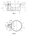
- FIG. 1 shows a schematic side view of a housing 1, which comprises a main space 2 and a side space 3.
- the main space 2 and the side space 3 are connected to each other.
- the main room 2 and the side room 3 serve to receive water.
- the main space 2 is surrounded by a side wall 4 of the housing 1.
- the side space 3 is also bounded by the side wall 20 of the housing.
- the side wall 4 is formed higher in the region of the main space 2 than in the region of the side space 3.
- the side space 3 is covered by a cover 5.
- the lid 5 has a filler neck 6 and a guide tube 7 for a level indicator.
- a display rod 8 is movably mounted, at the lower end of a float 9 is fixed.
- the floating body 9 floats in different positions, so that the upper end of the indicator bar 8 differs from the guide tube 7 projects upwards.
- the filler neck 6 and the guide tube 7 are equal length led out of the top 5.
- the filler neck 6 and the guide tube 7 terminate above an edge region 10 which delimits the main space 2.
- the side wall 4 is closed at the bottom by a bottom 11.
- a plant pot 13 is shown in dashed lines.
- the plant pot 13 has in the bottom openings through which absorbent threads 14 are guided down to the bottom 11.
- the plant pot 13 has an annular circumferential, downwardly curved peripheral edge 15 on.
- the plant pot 13 is set in a receiving opening 16 of the housing, wherein the peripheral edge 15 covers the peripheral edge region 10 of the receiving opening 16.
- a surface 17 of a layer of earth 18 is shown, with which the device can be built over.
- the side wall 4 of the housing 1 is either covered with a layer of soil 18 or covered by the plant pot 13.
- the cover 5 is also covered by the earth layer 18.
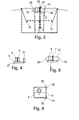
- FIG. 2 shows the device from above.
- the side wall 4, which surrounds the main space 2 is circular except for the area in which the main space 2 merges into the side space 3.
- the side wall 4 is formed starting from the upper edge region 10 in the direction of the bottom 11 inclined inwardly.
- the inclination is concentric with respect to a circle center 19.
- the inclination may be between 0.5 and for example 5 °. Usually, the inclination is in the range of 1 °.
- the side wall 4 limits the side space 3 on three sides.
- the side space 3 has a rectangular shape in cross-section, which opens into the circular shape of the main space 2.
- the three sides of the side wall 4 are preferably arranged starting from an upper edge region in the direction of the bottom 11 in each case inclined inwards. The inclination is for example between 0.5 and 5%. A usual value is in the range of 1%.
- a different cross-sectional shape in particular a circular shape can be selected.
- FIG. 2 the lid 5 is shown with the filler neck 6 and the guide tube 7. On the display bar 8 has been omitted.
- the lid 5 has a side wall portion 21 which engages with side tabs 22, the side wall 4 adjacent to the side space 3.
- the side wall part 21 is inserted in a cutout 23 of the side wall 4.
- the cutout 23 is formed in the transition region 24 between the main space 2 and the side space 3.
- the cutout 23 is formed by two parallel side edges 25 of the housing 1.
- the lid has 5 notches 26, in which engage the side edges 25.
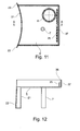
- FIG. 3 shows a schematic side view of the device, wherein the tabs 22 of the side wall portion 21 are shown in dashed lines.
- the tabs 22 engage behind the opposite side edges 25 of the side wall 4 above the lid 5.
- the cover 5 has a covering on the three sides of the second side wall 20 lid edge 27. As a result, the opening of the side space 3 with the cover 5 is also covered laterally so that no overfilled earth can fall into the side space 3.
- FIG. 4 shows the lid 5 in a first side view. It can be seen that the side wall portion 21 is arranged at right angles to the base surface of the lid 5. In addition, the part-circular bending of the side wall portion 21 can be seen.
- FIG. 5 shows the lid 5 in a second view, in which it can be seen that the lateral tabs 22 of the side wall portion 21 protrude laterally beyond the lid 5.
- FIG. 6 shows the lid 5 from above, wherein the notches 26 for receiving the side edges 25 of the side wall 4 are clearly visible.
- the side wall part 21 in cross section has a similar or the same shape as the side wall 4 of the main space 2.
- a circumferential closed support edge for the plant pot 13 is provided.
- the assembly of the lid 5 is easy and safe to perform. Due to the notches 26 and due to the tabs 22, the lid 5 is held on the housing 1 in the desired position.
- the lid edge 27 consists essentially of three side regions of the lid 5, which are each arranged at right angles to one another and are angled at right angles to the lid 5.
- the lid 5 may be formed of a more UV-stable material than the housing 1. This ensures that the filler neck 6 and the guide tube 7, which protrudes from the earth layer 18 in the installed state, is not destroyed by UV radiation.
- the upper edge of the side wall part 21 is arranged at the same height as the upper edge of the side wall 4 in the region of the main space 2.
- FIG. 7 shows a further embodiment of the device, wherein the housing 1 in the region of the main space 2 has a stepped and tapered towards the bottom cylindrical shape.
- a first upper cylindrical ring 30 is conically tapered in the direction of the bottom 11.
- the first cylinder ring 30 merges via an annular surface 31 into a second cylinder ring 32, which is connected to the base 11.
- the annular surface 31 is preferably arranged perpendicular to a central axis of symmetry 41 of the first and second cylinder rings 30, 32.
- overflow openings 12 are arranged.
- the second cylinder ring 32 is also conically tapered in the direction of the bottom 11. Due to the arrangement of the annular surface 31, a simple and cost-effective production of the overflow openings 12 is possible.
- the first and second cylinder rings 30, 32 and the annular surface 31 have corresponding openings in the transition region 24 to the side space 3, so that the first and the second cylinder ring 30, 32 and the annular surface 31 actually represent only partial rings.
- the housing 1 on the bottom 11 webs 33, which are performed radially symmetrically starting from the second cylinder ring 32 in the direction of the center of the bottom 11.
- the webs 33 represent a three-step reinforcing cross.
- the webs 33 each have a leg 34 on the second cylinder ring 32, which is guided from the web 33 a predetermined distance parallel to the center axis 41 of the cylinder rings 30, 32 and along the second cylinder ring 32.
- the housing 1 is made for example of a plastic, wherein the webs 33, despite a thin side wall 4 and a thin bottom 11 allow increased stability of the housing 1.
- FIG. 7 is a further embodiment of the lid 5 is shown, wherein the cover 5 has a second wall portion 21 which is ajar from the outside to the first cylinder ring 30 with lateral edge regions.
- the lid 5 is secured by a further web 35 against a radially outward displacement.
- FIG. 8 shows a view of the housing 1 of FIG. 7 without cover 5. Also in this embodiment, the side walls of the side space 3 are arranged in the direction of the bottom 11 inclined inwards.
- FIG. 9 shows a cross section AA of FIG. 8 , In this case, the annular surface 31 arranged essentially perpendicular to the center axis 36 can be clearly seen.
- FIG. 10 shows a cross section BB of FIG. 8 .
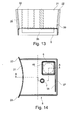
- FIG. 11 shows a plan view of the lid 5 of FIG. 7 , wherein the further web 35 is shown in dashed lines.
- the side wall part 21 is formed in accordance with the conically inclined arrangement of the first cylinder ring 30 and has laterally to the lid 5 in each case tabs 22 which rest in the mounted state on corresponding side surfaces of the first cylinder ring 30.
- FIG. 12 shows a cross section AA of FIG. 11 , In this case, the further web 35 is shown, which forms a groove 38 with a rear side edge 37 of the cover 5, in which engages a rear side 42 of the side space 3 after the mounting of the lid 5 on the side space 3.
- FIG. 13 shows a view of the side wall portion 21 of the lid 5, wherein 22 sealing surfaces 39 are provided for sealing engagement with the first cylinder ring 30 in the region of the tabs.
- FIG. 14 shows a further embodiment of the lid 5 of FIG. 11 , wherein the lid 5 according to the embodiment of the FIG. 11 is trained.
- the lid 5 of the embodiment of the FIG. 14 has the lid 5 of the embodiment of the FIG. 14 a filler neck 6, which is not circular in cross-section, but rectangular.
Landscapes
- Engineering & Computer Science (AREA)
- Water Supply & Treatment (AREA)
- Life Sciences & Earth Sciences (AREA)
- Environmental Sciences (AREA)
- Cultivation Receptacles Or Flower-Pots, Or Pots For Seedlings (AREA)
Applications Claiming Priority (1)
| Application Number | Priority Date | Filing Date | Title |
|---|---|---|---|
| DE102012205219A DE102012205219A1 (de) | 2012-03-30 | 2012-03-30 | Vorrichtung zum Aufnehmen eines Pflanzentopfes |
Publications (2)
| Publication Number | Publication Date |
|---|---|
| EP2644024A1 true EP2644024A1 (fr) | 2013-10-02 |
| EP2644024B1 EP2644024B1 (fr) | 2015-01-07 |
Family
ID=48087369
Family Applications (1)
| Application Number | Title | Priority Date | Filing Date |
|---|---|---|---|
| EP20130160834 Active EP2644024B1 (fr) | 2012-03-30 | 2013-03-25 | Dispositif destiné à recevoir un pot de fleur |
Country Status (2)
| Country | Link |
|---|---|
| EP (1) | EP2644024B1 (fr) |
| DE (1) | DE102012205219A1 (fr) |
Cited By (10)
| Publication number | Priority date | Publication date | Assignee | Title |
|---|---|---|---|---|
| USD782924S1 (en) | 2015-09-24 | 2017-04-04 | Dotchi, Llc | Liquid level indicator |
| USD782925S1 (en) | 2015-09-24 | 2017-04-04 | Dotchi, Llc | Liquid level indicator |
| US9872446B2 (en) | 2015-09-24 | 2018-01-23 | Dotchi, Llc | Liquid level indicator |
| NL2017938B1 (nl) * | 2016-12-06 | 2018-06-29 | Van Dorp Cdp B V | Houder voor kweekmateriaal voor het daarin doen groeien van een plant |
| USD831532S1 (en) | 2017-01-27 | 2018-10-23 | Dotchi, Llc | Raised potting bed planter |
| US10285347B2 (en) | 2015-09-24 | 2019-05-14 | Dotchi, Llc | Water level indicator |
| USD872639S1 (en) | 2017-01-27 | 2020-01-14 | Dotchi, Llc | Modular landscape planter |
| USD876986S1 (en) | 2017-01-26 | 2020-03-03 | Dotchi, Llc | Planter with indicator shelf |
| US11528850B2 (en) | 2018-07-20 | 2022-12-20 | Dotchi, Llc | Insertable planter, system, and methods |
| DE102021120150B3 (de) | 2021-08-03 | 2023-01-26 | Schlosserei Klaus Schuler GmbH | Vorrichtung zum Aufnehmen eines Pflanzentopfs |
Citations (6)
| Publication number | Priority date | Publication date | Assignee | Title |
|---|---|---|---|---|
| FR2159786A5 (fr) * | 1971-11-12 | 1973-06-22 | Quennessen Rene | |
| EP0558456A1 (fr) * | 1992-02-24 | 1993-09-01 | Heebag A. Heeb Ag | Conteneur pour la délivrance contrôlée d'un liquide à un consommateur |
| EP0688497A1 (fr) * | 1994-06-23 | 1995-12-27 | Albin Heeb AG | Dispositif pour bacs à plantes |
| EP2018804A1 (fr) * | 2007-07-27 | 2009-01-28 | Hobby-Flower De España, S.A. | Jardinière |
| US20090056219A1 (en) * | 2007-09-05 | 2009-03-05 | Lajos Csoke | Self-watering plant container |
| US20110162272A1 (en) * | 2008-09-16 | 2011-07-07 | Gerald Junkeer | Container gardening system |
-
2012
- 2012-03-30 DE DE102012205219A patent/DE102012205219A1/de not_active Withdrawn
-
2013
- 2013-03-25 EP EP20130160834 patent/EP2644024B1/fr active Active
Patent Citations (6)
| Publication number | Priority date | Publication date | Assignee | Title |
|---|---|---|---|---|
| FR2159786A5 (fr) * | 1971-11-12 | 1973-06-22 | Quennessen Rene | |
| EP0558456A1 (fr) * | 1992-02-24 | 1993-09-01 | Heebag A. Heeb Ag | Conteneur pour la délivrance contrôlée d'un liquide à un consommateur |
| EP0688497A1 (fr) * | 1994-06-23 | 1995-12-27 | Albin Heeb AG | Dispositif pour bacs à plantes |
| EP2018804A1 (fr) * | 2007-07-27 | 2009-01-28 | Hobby-Flower De España, S.A. | Jardinière |
| US20090056219A1 (en) * | 2007-09-05 | 2009-03-05 | Lajos Csoke | Self-watering plant container |
| US20110162272A1 (en) * | 2008-09-16 | 2011-07-07 | Gerald Junkeer | Container gardening system |
Cited By (11)
| Publication number | Priority date | Publication date | Assignee | Title |
|---|---|---|---|---|
| USD782924S1 (en) | 2015-09-24 | 2017-04-04 | Dotchi, Llc | Liquid level indicator |
| USD782925S1 (en) | 2015-09-24 | 2017-04-04 | Dotchi, Llc | Liquid level indicator |
| US9872446B2 (en) | 2015-09-24 | 2018-01-23 | Dotchi, Llc | Liquid level indicator |
| US10285346B2 (en) | 2015-09-24 | 2019-05-14 | Dotchi, Llc | Water level indicator |
| US10285347B2 (en) | 2015-09-24 | 2019-05-14 | Dotchi, Llc | Water level indicator |
| NL2017938B1 (nl) * | 2016-12-06 | 2018-06-29 | Van Dorp Cdp B V | Houder voor kweekmateriaal voor het daarin doen groeien van een plant |
| USD876986S1 (en) | 2017-01-26 | 2020-03-03 | Dotchi, Llc | Planter with indicator shelf |
| USD831532S1 (en) | 2017-01-27 | 2018-10-23 | Dotchi, Llc | Raised potting bed planter |
| USD872639S1 (en) | 2017-01-27 | 2020-01-14 | Dotchi, Llc | Modular landscape planter |
| US11528850B2 (en) | 2018-07-20 | 2022-12-20 | Dotchi, Llc | Insertable planter, system, and methods |
| DE102021120150B3 (de) | 2021-08-03 | 2023-01-26 | Schlosserei Klaus Schuler GmbH | Vorrichtung zum Aufnehmen eines Pflanzentopfs |
Also Published As
| Publication number | Publication date |
|---|---|
| EP2644024B1 (fr) | 2015-01-07 |
| DE102012205219A1 (de) | 2013-10-02 |
Similar Documents
| Publication | Publication Date | Title |
|---|---|---|
| EP2644024A1 (fr) | Dispositif destiné à recevoir un pot de fleur | |
| DE102015121192B4 (de) | Rahmengestell für einen Schaltschrank | |
| DE3141357A1 (de) | Gefaess fuer pflanzenkulturen | |
| EP2808458B1 (fr) | Dispositif d'écoulement d'eau pour une douche et élément de sol de douche | |
| DE19840593A1 (de) | Vorrichtung zur Herstellung einer Flachdach-Entwässerung | |
| DE102008030715A1 (de) | Hydraulikaggregat | |
| DE3144517A1 (de) | Fuellkoerper | |
| DE202006008917U1 (de) | Luftdurchlässiges Verschlusselement für geschlossene Geräte | |
| EP1013843B1 (fr) | Evacuation d'eau à écoulement libre | |
| DE3644100C2 (fr) | ||
| DE202018106835U1 (de) | Pflanztopf mit Bewässerungssystem | |
| DE3524923A1 (de) | Umzaeunung | |
| EP1022390A1 (fr) | Caniveau | |
| AT525300B1 (de) | Vorrichtung zum Aufnehmen eines Pflanzentopfs | |
| EP2641307B1 (fr) | Dispositif formant goulotte d'expulsion et limiteur de surtension | |
| DE19949697B4 (de) | Vorrichtung zum Verschliessen von Rohrenden | |
| DE19906616C2 (de) | Behälter mit einer flachen Halteöse | |
| DE3244502C2 (de) | Mauerkasten | |
| DE202016106530U1 (de) | Aus Blech bestehende Dränage- oder Entwässerungsrinne | |
| DE60004177T2 (de) | Elektrisches Installationsgerät zum Aufschnappen auf eine Tragschiene | |
| EP4474584A1 (fr) | Siphon à insérer dans un corps de réception doté d'un embout de sortie | |
| DE202022105812U1 (de) | Gehäuse für ein technisches Versorgungs- und Infrastrukturgebäude, insbesondere eine Transformatorstation, mit einer begrünbaren Dachfläche | |
| DE202020101592U1 (de) | Blumenkasten | |
| EP3505703A1 (fr) | Système d'évacuation | |
| CH554470A (de) | Fenster-schacht. |
Legal Events
| Date | Code | Title | Description |
|---|---|---|---|
| PUAI | Public reference made under article 153(3) epc to a published international application that has entered the european phase |
Free format text: ORIGINAL CODE: 0009012 |
|
| AK | Designated contracting states |
Kind code of ref document: A1 Designated state(s): AL AT BE BG CH CY CZ DE DK EE ES FI FR GB GR HR HU IE IS IT LI LT LU LV MC MK MT NL NO PL PT RO RS SE SI SK SM TR |
|
| AX | Request for extension of the european patent |
Extension state: BA ME |
|
| 17P | Request for examination filed |
Effective date: 20140401 |
|
| RBV | Designated contracting states (corrected) |
Designated state(s): AL AT BE BG CH CY CZ DE DK EE ES FI FR GB GR HR HU IE IS IT LI LT LU LV MC MK MT NL NO PL PT RO RS SE SI SK SM TR |
|
| GRAP | Despatch of communication of intention to grant a patent |
Free format text: ORIGINAL CODE: EPIDOSNIGR1 |
|
| INTG | Intention to grant announced |
Effective date: 20140807 |
|
| GRAS | Grant fee paid |
Free format text: ORIGINAL CODE: EPIDOSNIGR3 |
|
| GRAA | (expected) grant |
Free format text: ORIGINAL CODE: 0009210 |
|
| AK | Designated contracting states |
Kind code of ref document: B1 Designated state(s): AL AT BE BG CH CY CZ DE DK EE ES FI FR GB GR HR HU IE IS IT LI LT LU LV MC MK MT NL NO PL PT RO RS SE SI SK SM TR |
|
| REG | Reference to a national code |
Ref country code: GB Ref legal event code: FG4D Free format text: NOT ENGLISH |
|
| REG | Reference to a national code |
Ref country code: CH Ref legal event code: EP |
|
| REG | Reference to a national code |
Ref country code: IE Ref legal event code: FG4D Free format text: LANGUAGE OF EP DOCUMENT: GERMAN |
|
| REG | Reference to a national code |
Ref country code: AT Ref legal event code: REF Ref document number: 705020 Country of ref document: AT Kind code of ref document: T Effective date: 20150215 |
|
| REG | Reference to a national code |
Ref country code: DE Ref legal event code: R096 Ref document number: 502013000279 Country of ref document: DE Effective date: 20150219 |
|
| REG | Reference to a national code |
Ref country code: NL Ref legal event code: VDEP Effective date: 20150107 |
|
| REG | Reference to a national code |
Ref country code: LT Ref legal event code: MG4D |
|
| PG25 | Lapsed in a contracting state [announced via postgrant information from national office to epo] |
Ref country code: HR Free format text: LAPSE BECAUSE OF FAILURE TO SUBMIT A TRANSLATION OF THE DESCRIPTION OR TO PAY THE FEE WITHIN THE PRESCRIBED TIME-LIMIT Effective date: 20150107 Ref country code: BG Free format text: LAPSE BECAUSE OF FAILURE TO SUBMIT A TRANSLATION OF THE DESCRIPTION OR TO PAY THE FEE WITHIN THE PRESCRIBED TIME-LIMIT Effective date: 20150407 Ref country code: LT Free format text: LAPSE BECAUSE OF FAILURE TO SUBMIT A TRANSLATION OF THE DESCRIPTION OR TO PAY THE FEE WITHIN THE PRESCRIBED TIME-LIMIT Effective date: 20150107 Ref country code: SE Free format text: LAPSE BECAUSE OF FAILURE TO SUBMIT A TRANSLATION OF THE DESCRIPTION OR TO PAY THE FEE WITHIN THE PRESCRIBED TIME-LIMIT Effective date: 20150107 Ref country code: FI Free format text: LAPSE BECAUSE OF FAILURE TO SUBMIT A TRANSLATION OF THE DESCRIPTION OR TO PAY THE FEE WITHIN THE PRESCRIBED TIME-LIMIT Effective date: 20150107 Ref country code: NO Free format text: LAPSE BECAUSE OF FAILURE TO SUBMIT A TRANSLATION OF THE DESCRIPTION OR TO PAY THE FEE WITHIN THE PRESCRIBED TIME-LIMIT Effective date: 20150407 Ref country code: ES Free format text: LAPSE BECAUSE OF FAILURE TO SUBMIT A TRANSLATION OF THE DESCRIPTION OR TO PAY THE FEE WITHIN THE PRESCRIBED TIME-LIMIT Effective date: 20150107 |
|
| PG25 | Lapsed in a contracting state [announced via postgrant information from national office to epo] |
Ref country code: PL Free format text: LAPSE BECAUSE OF FAILURE TO SUBMIT A TRANSLATION OF THE DESCRIPTION OR TO PAY THE FEE WITHIN THE PRESCRIBED TIME-LIMIT Effective date: 20150107 Ref country code: RS Free format text: LAPSE BECAUSE OF FAILURE TO SUBMIT A TRANSLATION OF THE DESCRIPTION OR TO PAY THE FEE WITHIN THE PRESCRIBED TIME-LIMIT Effective date: 20150107 Ref country code: IS Free format text: LAPSE BECAUSE OF FAILURE TO SUBMIT A TRANSLATION OF THE DESCRIPTION OR TO PAY THE FEE WITHIN THE PRESCRIBED TIME-LIMIT Effective date: 20150507 Ref country code: LV Free format text: LAPSE BECAUSE OF FAILURE TO SUBMIT A TRANSLATION OF THE DESCRIPTION OR TO PAY THE FEE WITHIN THE PRESCRIBED TIME-LIMIT Effective date: 20150107 Ref country code: NL Free format text: LAPSE BECAUSE OF FAILURE TO SUBMIT A TRANSLATION OF THE DESCRIPTION OR TO PAY THE FEE WITHIN THE PRESCRIBED TIME-LIMIT Effective date: 20150107 Ref country code: GR Free format text: LAPSE BECAUSE OF FAILURE TO SUBMIT A TRANSLATION OF THE DESCRIPTION OR TO PAY THE FEE WITHIN THE PRESCRIBED TIME-LIMIT Effective date: 20150408 |
|
| REG | Reference to a national code |
Ref country code: DE Ref legal event code: R097 Ref document number: 502013000279 Country of ref document: DE |
|
| PG25 | Lapsed in a contracting state [announced via postgrant information from national office to epo] |
Ref country code: RO Free format text: LAPSE BECAUSE OF FAILURE TO SUBMIT A TRANSLATION OF THE DESCRIPTION OR TO PAY THE FEE WITHIN THE PRESCRIBED TIME-LIMIT Effective date: 20150107 Ref country code: CZ Free format text: LAPSE BECAUSE OF FAILURE TO SUBMIT A TRANSLATION OF THE DESCRIPTION OR TO PAY THE FEE WITHIN THE PRESCRIBED TIME-LIMIT Effective date: 20150107 Ref country code: EE Free format text: LAPSE BECAUSE OF FAILURE TO SUBMIT A TRANSLATION OF THE DESCRIPTION OR TO PAY THE FEE WITHIN THE PRESCRIBED TIME-LIMIT Effective date: 20150107 Ref country code: LU Free format text: LAPSE BECAUSE OF FAILURE TO SUBMIT A TRANSLATION OF THE DESCRIPTION OR TO PAY THE FEE WITHIN THE PRESCRIBED TIME-LIMIT Effective date: 20150325 Ref country code: DK Free format text: LAPSE BECAUSE OF FAILURE TO SUBMIT A TRANSLATION OF THE DESCRIPTION OR TO PAY THE FEE WITHIN THE PRESCRIBED TIME-LIMIT Effective date: 20150107 Ref country code: SK Free format text: LAPSE BECAUSE OF FAILURE TO SUBMIT A TRANSLATION OF THE DESCRIPTION OR TO PAY THE FEE WITHIN THE PRESCRIBED TIME-LIMIT Effective date: 20150107 Ref country code: MC Free format text: LAPSE BECAUSE OF FAILURE TO SUBMIT A TRANSLATION OF THE DESCRIPTION OR TO PAY THE FEE WITHIN THE PRESCRIBED TIME-LIMIT Effective date: 20150107 |
|
| PLBE | No opposition filed within time limit |
Free format text: ORIGINAL CODE: 0009261 |
|
| STAA | Information on the status of an ep patent application or granted ep patent |
Free format text: STATUS: NO OPPOSITION FILED WITHIN TIME LIMIT |
|
| 26N | No opposition filed |
Effective date: 20151008 |
|
| PG25 | Lapsed in a contracting state [announced via postgrant information from national office to epo] |
Ref country code: IT Free format text: LAPSE BECAUSE OF FAILURE TO SUBMIT A TRANSLATION OF THE DESCRIPTION OR TO PAY THE FEE WITHIN THE PRESCRIBED TIME-LIMIT Effective date: 20150107 |
|
| REG | Reference to a national code |
Ref country code: FR Ref legal event code: ST Effective date: 20151130 |
|
| REG | Reference to a national code |
Ref country code: IE Ref legal event code: MM4A |
|
| PG25 | Lapsed in a contracting state [announced via postgrant information from national office to epo] |
Ref country code: IE Free format text: LAPSE BECAUSE OF NON-PAYMENT OF DUE FEES Effective date: 20150325 |
|
| PG25 | Lapsed in a contracting state [announced via postgrant information from national office to epo] |
Ref country code: SI Free format text: LAPSE BECAUSE OF FAILURE TO SUBMIT A TRANSLATION OF THE DESCRIPTION OR TO PAY THE FEE WITHIN THE PRESCRIBED TIME-LIMIT Effective date: 20150107 Ref country code: FR Free format text: LAPSE BECAUSE OF NON-PAYMENT OF DUE FEES Effective date: 20150331 |
|
| PG25 | Lapsed in a contracting state [announced via postgrant information from national office to epo] |
Ref country code: MT Free format text: LAPSE BECAUSE OF FAILURE TO SUBMIT A TRANSLATION OF THE DESCRIPTION OR TO PAY THE FEE WITHIN THE PRESCRIBED TIME-LIMIT Effective date: 20150107 |
|
| PG25 | Lapsed in a contracting state [announced via postgrant information from national office to epo] |
Ref country code: HU Free format text: LAPSE BECAUSE OF FAILURE TO SUBMIT A TRANSLATION OF THE DESCRIPTION OR TO PAY THE FEE WITHIN THE PRESCRIBED TIME-LIMIT; INVALID AB INITIO Effective date: 20130325 |
|
| PG25 | Lapsed in a contracting state [announced via postgrant information from national office to epo] |
Ref country code: CY Free format text: LAPSE BECAUSE OF FAILURE TO SUBMIT A TRANSLATION OF THE DESCRIPTION OR TO PAY THE FEE WITHIN THE PRESCRIBED TIME-LIMIT Effective date: 20150107 |
|
| PG25 | Lapsed in a contracting state [announced via postgrant information from national office to epo] |
Ref country code: BE Free format text: LAPSE BECAUSE OF NON-PAYMENT OF DUE FEES Effective date: 20150331 |
|
| PG25 | Lapsed in a contracting state [announced via postgrant information from national office to epo] |
Ref country code: TR Free format text: LAPSE BECAUSE OF FAILURE TO SUBMIT A TRANSLATION OF THE DESCRIPTION OR TO PAY THE FEE WITHIN THE PRESCRIBED TIME-LIMIT Effective date: 20150107 |
|
| GBPC | Gb: european patent ceased through non-payment of renewal fee |
Effective date: 20170325 |
|
| PG25 | Lapsed in a contracting state [announced via postgrant information from national office to epo] |
Ref country code: GB Free format text: LAPSE BECAUSE OF NON-PAYMENT OF DUE FEES Effective date: 20170325 |
|
| PG25 | Lapsed in a contracting state [announced via postgrant information from national office to epo] |
Ref country code: SM Free format text: LAPSE BECAUSE OF FAILURE TO SUBMIT A TRANSLATION OF THE DESCRIPTION OR TO PAY THE FEE WITHIN THE PRESCRIBED TIME-LIMIT Effective date: 20150107 |
|
| PG25 | Lapsed in a contracting state [announced via postgrant information from national office to epo] |
Ref country code: PT Free format text: LAPSE BECAUSE OF FAILURE TO SUBMIT A TRANSLATION OF THE DESCRIPTION OR TO PAY THE FEE WITHIN THE PRESCRIBED TIME-LIMIT Effective date: 20150107 Ref country code: MK Free format text: LAPSE BECAUSE OF FAILURE TO SUBMIT A TRANSLATION OF THE DESCRIPTION OR TO PAY THE FEE WITHIN THE PRESCRIBED TIME-LIMIT Effective date: 20150107 |
|
| PG25 | Lapsed in a contracting state [announced via postgrant information from national office to epo] |
Ref country code: AL Free format text: LAPSE BECAUSE OF FAILURE TO SUBMIT A TRANSLATION OF THE DESCRIPTION OR TO PAY THE FEE WITHIN THE PRESCRIBED TIME-LIMIT Effective date: 20150107 |
|
| PGFP | Annual fee paid to national office [announced via postgrant information from national office to epo] |
Ref country code: AT Payment date: 20230317 Year of fee payment: 11 |
|
| PGFP | Annual fee paid to national office [announced via postgrant information from national office to epo] |
Ref country code: CH Payment date: 20230402 Year of fee payment: 11 |
|
| REG | Reference to a national code |
Ref country code: CH Ref legal event code: PL |
|
| REG | Reference to a national code |
Ref country code: AT Ref legal event code: MM01 Ref document number: 705020 Country of ref document: AT Kind code of ref document: T Effective date: 20240325 |
|
| PG25 | Lapsed in a contracting state [announced via postgrant information from national office to epo] |
Ref country code: AT Free format text: LAPSE BECAUSE OF NON-PAYMENT OF DUE FEES Effective date: 20240325 |
|
| PG25 | Lapsed in a contracting state [announced via postgrant information from national office to epo] |
Ref country code: AT Free format text: LAPSE BECAUSE OF NON-PAYMENT OF DUE FEES Effective date: 20240325 Ref country code: CH Free format text: LAPSE BECAUSE OF NON-PAYMENT OF DUE FEES Effective date: 20240331 |
|
| PGFP | Annual fee paid to national office [announced via postgrant information from national office to epo] |
Ref country code: DE Payment date: 20260312 Year of fee payment: 14 |