EP2644065A1 - Construction d'ouverture de boîte à lettres pour installations de boîte à lettres - Google Patents
Construction d'ouverture de boîte à lettres pour installations de boîte à lettres Download PDFInfo
- Publication number
- EP2644065A1 EP2644065A1 EP12161658.5A EP12161658A EP2644065A1 EP 2644065 A1 EP2644065 A1 EP 2644065A1 EP 12161658 A EP12161658 A EP 12161658A EP 2644065 A1 EP2644065 A1 EP 2644065A1
- Authority
- EP
- European Patent Office
- Prior art keywords
- flap
- bearing
- letter
- insert according
- opening
- Prior art date
- Legal status (The legal status is an assumption and is not a legal conclusion. Google has not performed a legal analysis and makes no representation as to the accuracy of the status listed.)
- Granted
Links
- 238000003780 insertion Methods 0.000 description 38
- 230000037431 insertion Effects 0.000 description 37
- 229910052751 metal Inorganic materials 0.000 description 4
- 239000002184 metal Substances 0.000 description 4
- 238000009434 installation Methods 0.000 description 3
- 239000000463 material Substances 0.000 description 3
- 230000002093 peripheral effect Effects 0.000 description 3
- 229910052782 aluminium Inorganic materials 0.000 description 2
- XAGFODPZIPBFFR-UHFFFAOYSA-N aluminium Chemical compound [Al] XAGFODPZIPBFFR-UHFFFAOYSA-N 0.000 description 2
- 238000013016 damping Methods 0.000 description 2
- 238000006073 displacement reaction Methods 0.000 description 2
- 230000005294 ferromagnetic effect Effects 0.000 description 2
- 238000010137 moulding (plastic) Methods 0.000 description 2
- 238000007789 sealing Methods 0.000 description 2
- 229910001220 stainless steel Inorganic materials 0.000 description 2
- 239000010935 stainless steel Substances 0.000 description 2
- 230000006978 adaptation Effects 0.000 description 1
- 239000000853 adhesive Substances 0.000 description 1
- 230000001070 adhesive effect Effects 0.000 description 1
- 238000004891 communication Methods 0.000 description 1
- 230000000295 complement effect Effects 0.000 description 1
- 230000001419 dependent effect Effects 0.000 description 1
- 238000001514 detection method Methods 0.000 description 1
- 238000011161 development Methods 0.000 description 1
- 230000018109 developmental process Effects 0.000 description 1
- 239000013536 elastomeric material Substances 0.000 description 1
- 238000009472 formulation Methods 0.000 description 1
- 238000009413 insulation Methods 0.000 description 1
- 238000002372 labelling Methods 0.000 description 1
- 230000005291 magnetic effect Effects 0.000 description 1
- 239000000203 mixture Substances 0.000 description 1
- 238000000465 moulding Methods 0.000 description 1
- 230000001953 sensory effect Effects 0.000 description 1
- XLYOFNOQVPJJNP-UHFFFAOYSA-N water Substances O XLYOFNOQVPJJNP-UHFFFAOYSA-N 0.000 description 1
Images




Classifications
-
- A—HUMAN NECESSITIES
- A47—FURNITURE; DOMESTIC ARTICLES OR APPLIANCES; COFFEE MILLS; SPICE MILLS; SUCTION CLEANERS IN GENERAL
- A47G—HOUSEHOLD OR TABLE EQUIPMENT
- A47G29/00—Supports, holders, or containers for household use, not provided for in groups A47G1/00-A47G27/00 or A47G33/00
- A47G29/12—Mail or newspaper receptacles, e.g. letter-boxes; Openings in doors or the like for delivering mail or newspapers
- A47G29/122—Parts, details, or accessories, e.g. signalling devices, lamps, devices for leaving messages
- A47G29/126—Lids for access slits
-
- A—HUMAN NECESSITIES
- A47—FURNITURE; DOMESTIC ARTICLES OR APPLIANCES; COFFEE MILLS; SPICE MILLS; SUCTION CLEANERS IN GENERAL
- A47G—HOUSEHOLD OR TABLE EQUIPMENT
- A47G29/00—Supports, holders, or containers for household use, not provided for in groups A47G1/00-A47G27/00 or A47G33/00
- A47G29/12—Mail or newspaper receptacles, e.g. letter-boxes; Openings in doors or the like for delivering mail or newspapers
- A47G29/1201—Letter-box assemblies for apartment buildings
Definitions
- the present invention relates according to the preamble of independent claim 1 a letter box for mailboxes, letter throws and the like, consisting of a Einschcken with a slot-shaped letter-throw opening and a flap, which has a flap storage between the insertion opening overlapping closing position and a Insertion opening for Posteinsch releasing opening position is pivotally mounted about a pivot axis.
- Mailboxes for receiving incoming mail in the entrance area of residential buildings are well known in a variety of designs. Often they are self-contained boxes that z. B. are to be mounted on a wall surface of a building in the outer entrance area. Furthermore, mailboxes are also often installed in larger systems and sometimes combined with bell buttons and / or other functional components. Such systems can be installed in a wall area adjacent to a front door or as free-standing systems in front of a building. In this context, certain requirements for letterboxes and letterbox systems are specified in the relevant, EU-wide binding standard EN 13724.
- the present invention is based on the object, to create a pleasing appearance appearance of a letter insert the beginning described, generic type so that it is with its closed flap in the immediate vicinity, ie with only small gap distances, mounted to adjacent functional components and then a front visible surface of the flap in its closed position in a common plane with front surfaces of the adjacent components. Nevertheless, while the largest possible pivot angle between the closed position and the open position should be possible.
- the flap bearing is accommodated in a flap edge region parallel to the geometric pivot axis within the material cross section of the flap so that the edge flap region rotates about the pivot axis during lateral movements of the flap without lateral displacement perpendicular to the pivot axis.
- the edge region of the flap is relative to the Einschisme - apart from the rotation - out in a stationary manner, so that during the pivoting movements of the flap the respective distance to adjacent functional components is maintained.
- very small gap distances in particular in the range of only 1 mm, without affecting the pivoting movements of the flap can be realized.
- the fact that the geometric pivot axis runs very close to the outer edge boundary of the flap, yet even with such a small gap distance, a large swing angle can be achieved, which in any case is greater than 90 ° and can advantageously be up to 120 °.
- each pivot bearing has a fixed to the insertion support and engaging through a peripheral opening in a formed within the insertion flap bearing receiving axle portion, wherein the axle portions of the pivot bearings are aligned with their longitudinal axes on the geometric pivot axis and jointly define the pivot axis.
- the geometric pivot axis thus also runs through the special arrangement of the axle sections also within the edge region of the flap.
- the edge region of the insertion flap which receives the flap bearing has a convexly circular-arc-rounded rounded edge outer surface which is coaxial with the pivot axis. Consequently, this circular arcuate edge outer surface extends, starting from the front visible surface of the flap, at least over half a circumference to the rear of the flap.
- the flap bearing is advantageously designed so that the geometric pivot axis runs as close to the outer flap boundary;
- the radius of curvature of the circular-arc-shaped edge outer surface measured from the pivot axis is preferably only 2 mm to a maximum of 3 mm.
- the flap is expedient at least two layers of a base part and a front part, wherein the base part and the front part are formed in the region of the pivot bearing as bearing shells, which form between them the bearing receivers for the axle sections of the pivot bearing.
- the front part can preferably be made as a "design element" of metal, in particular of stainless steel or aluminum, wherein the front part as a bearing shell has only a marginal, folded web which extends over the entire length or width of the flap.
- the inner contour of the bearing receptacles is formed mainly in the base part by a corresponding shape, which is why the base part is preferably formed as a plastic molding.
- the pivot bearings are first used with the Achsabroughen in the bearing mounts of the base part. Then the front part is connected to the base part, glued in particular, whereby the bearing receptacles are closed so that the axle sections of the pivot bearings are held rotatably.
- the throw-in support has a projecting guide web adjoining the edge region of the flap which has the flap bearing with a guide surface which is rounded in a concave circular arc in cross-section.
- This guide surface extends - also coaxial with the geometric pivot axis - over a quarter circle circumference.
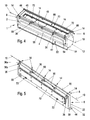
- FIG. 1 to 4 there is an inventive letter insert 1 from a throw-in carrier 2 with a narrow, slit-shaped letter-insertion opening 4 (see Fig. 2 and 4 ) as well as from an insertion flap 6.
- This insertion flap 6 is mounted on the flap carrier 8 via a flap bearing 8 such that it lies between a closing position covering the throw - in opening 4 (see FIG Fig. 1 and 3 ) and the opening opening 4 releasing opening position (see Fig. 2 and 4 ) is pivotable about a geometric pivot axis 10.
- the pivoting movement of the flap 6 is in Fig. 2 . 3 and 4 each illustrated by a double arrow 12.
- the geometric pivot axis 10 is in Fig.
- the flap bearing 8 is now housed in a corresponding to the course of the pivot axis 10 aligned, so practically parallel to the pivot axis 10 flap edge region within the material cross section of the body of the flap 6, that during the pivoting movements of the flap 6 whose edge region without lateral, to the pivot axis 10 vertical displacement about the pivot axis 10 rotates.
- the flap bearing 8 is integrated in the insertion flap 6, so that outside the visible front surface area of the flap 6, no bearing parts survive.
- the letter insert 1 according to the invention Fig. 1 and 2 be mounted as "insertion module" that the flap 6 directly adjacent to other functional parts over only a small gap distances. This applies to their upper and lower limits as well as to the lateral, left and right boundaries.
- the flap bearing 8 consists of at least two, for example, as shown five, over the edge region of Insert flap 6 in the direction of the pivot axis 10 evenly distributed and spaced from each other arranged pivot bearings 14 (see in particular 4 and 5 and also Fig. 7 ).
- Each pivot bearing 14 has a fixed to the insertion support 2 and formed by a peripheral opening in a formed within the flap 6 storage receptacle 16 - see in particular Fig. 7 - engaging axle 18 on.
- the axle sections 18 of all pivot bearings 14 define together with their longitudinal axes 18a (FIG. Fig. 6 and 7 In other words, all shaft sections 18 are aligned with their longitudinal axes 18a on the pivot axis 10. Due to the integrated arrangement of the axle 18 within the edge region of the flap 6 thus also the geometric pivot axis 10 extends within the flap 6 in the edge region.
- FIG. 3 . 5 and 7 shows that the flap bearing 8 receiving edge region of the flap 6 with advantage seen in cross section a convex circular arc rounded and coaxial with the pivot axis 10 edge outer surface 20.
- This circular arcuate edge outer surface 20 connects directly to the front, planar surface 22 of the flap 6 and extends over a circumferential angle of at least 180 °, ie over at least one semicircle to the back of the flap flap 6, see in particular Fig. 3 , It can also be seen from this illustration that during a pivoting movement of the insertion flap 6 in the double arrow direction 12, the edge region receiving the flap bearing 8 only rotates about the pivot axis 10.
- the throw-in carrier 2 has a to the flap bearing 8 having edge portion of the flap 6 adjacent, projecting guide bar 24 with a concave in cross-section arcuate in adaptation to the edge outer surface 20 of the flap lid 6 rounded guide surface 26.
- This guide surface 26 extends in the circumferential direction over 90 °, ie over a quarter circle. This is especially on the excerpt magnification in Fig. 3a directed.
- the flap 31 is at least two layers of a base part 30 and a front part 32.
- the base part 30 and the front part 32 are formed in the region of the integrated pivot bearing 14 as a bearing shells, which form the bearing receivers 16 for the axle 18 between them.
- Fig. 7 can be used in the not yet connected state of the parts 30, 32 in the bearing receivers 16, the axle portions 18 of the pivot bearing 14. Thereafter, the bearing receivers 16 are closed by joining the parts 30, 32.
- the arcuate convex edge outer surface 20 is then proportionately, each about half, formed by the base part 30 and the front part 32.
- the front part 32 preferably consists as a design element of a metal sheet, in particular of stainless steel or aluminum. In the area of the integrated flap bearing 8, the front part 32 has only a bent edge web 34, which extends in cross-section approximately over a quarter circle arc.
- the base web 30 is preferably formed as a plastic molding, and the inner contours of the bearing receivers 16 are formed by molding mainly within the base member 30. Also this is especially on Fig. 7 directed.
- the base part 30 and the front part 32 can be connected together in any desired manner.
- each pivot bearing 14 is part of a separate bearing part 36 so that five bearing parts 36 are provided in the preferred embodiment with five pivot bearings 14.
- the individual bearing parts 36 are attached to the insertion support 2, in particular screwed.
- Each bearing part 36 is according to Fig. 7 as an angle piece with one end of the axle portion 18 having bearing leg 36a and a particular rectangular attachment leg 36b formed.
- the bearing leg 36a is inserted from the rear side of the base part 30 pointing away from the front part 32 through a peripheral cutout 38 of the base part 30 with the axle section 18 into the bearing receptacle 16.
- the fastening leg 36b then extends, starting from the bearing leg 36a, perpendicularly to the flap carrier 2 and in particular through a holding opening 40 and is fastened to the rear side of the flap carrier 2 by means of a retaining screw 42.
- the retaining screws 42 are with respect to their screw axes 42 a (see Fig. 3 ) aligned parallel to the flap support 2 and also to the front surface 22 of the flap 6 in its closed position and extend through aligned mounting holes of the flap carrier 2 and the mounting leg 36 b of the respective bearing part 36th
- the insertion flap 6 in its flap region 8 opposite edge region on a front handle bar 44, which is fastened in particular via screw 46.
- screw 46 consist of screws 46 a, which are screwed through aligned openings 46 b and 46 c of the base member 30 and the front part 32 into unrecognizable threaded holes of the handle bar 44.
- the adjoining the flap 6 surface area 50 is at least partially formed by a labeling part 54.
- a labeling part 54 may be a particular engraved nameplate 54a or a shield support 54b for releasably holding a label.
- the inscription part 54 can be detachably fixed and, in particular, via a magnet holder.
- the area covered by the inscription part 54 can be illuminated from the inside of the insertion carrier 2 via a light source arranged there.
- the area adjoining the flap 6 surface area 50 is at least partially formed by a strip-shaped facing part 56 which is glued in particular with the insertion carrier 2.
- the inscription part 54 and the veneering part 56 are adapted to the respective design, in particular material, in the area of the front surface 22 of the insertion flap 6.
- the throw-in carrier 2 has a lock 58 - see Fig. 9 - For locking and unlocking a letter removal not shown on.
- the type of lock 58 is basically arbitrary. It may be a mechanical lock, but also an electromechanical or electromagnetic lock.
- the lock 58 can be locked by means of a key 60 (FIG. Fig. 9 ) are mechanically operated, but in principle also sensory, keyword "keyless" (key-free).
- the lock 58 is a key lock, which is unlocked by a simple insertion movement of the key 60.
- the surface area 50 adjoining the insertion flap 6 has a slot-shaped and vertically aligned key opening 62 for passing through the socket wrench 60.
- the type of unlockable by means of the lock 58 letter removal is also arbitrary.
- the key opening 62 results in the advantageous possibility of illuminating this area from the inside of the insertion carrier 2 via a light source arranged there. This means that light of the illuminant is visible through the keyhole 62 from the front visible side.
- the illuminant can be driven, for example, for occupancy detection via suitable control means to signal whether a letter record is empty or occupied. This can be done, for example, with different colored light.
- any other functions can be signaled, for example, the operating state of a building alarm system.
- the insertion flap 6 is releasably locked in its closed position. This protection against rattling, for example by wind, is achieved.
- a magnetic fixation is provided for this purpose.
- at least one magnet 64 which cooperates with a ferromagnetic surface region 66 of the insertion flap 6, is arranged on the insertion carrier 2. This is in particular on Fig. 4 directed.
- the ferromagnetic surface region 66 is preferably formed by a piece of a metal sheet 66a, said sheet metal piece 66a is inserted into a pocket-like receptacle of the base part 30 of the flap 6.
- the insertion flap 6 has on its inside a seal 68 for sealing engagement in the letter insertion opening 4 of the insertion carrier 2.
- a seal against ingress of moisture and dirt is achieved and on the other hand, a thermal insulation.
- the seal 68 is elongated frame-like formed of an elastomeric material.
- the seal 68 is held by a retaining strip 70 by the retaining strip 70 under Liner of the seal 68 is screwed to the base member 30. With the seal 68 engages the insertion flap 6 in its closed position non-positively and / or positively in the insertion opening 4 and circumferentially acts sealingly with the opening edge together.
- the insertion flap 6 on its inner side damper elements 72 for damping the stop in the pivoting movement from the open position to the closed position.
- the damper elements 72 may advantageously be one-piece, tab-like projections of the seal 68.
- For damping the damper elements 72 act on closing force-fit or kraftformschlüssig with the opening edge of the insertion opening 4 together.
- the insertion carrier 2 in the area of the letter insertion opening 4 on a removal protection 74 in particular in the form of an inwardly projecting web on the lower opening side.
- the letter insert 1 according to the invention can be combined as a throw-in module with any mailbox systems.
- a box-shaped receiving part 76 are arranged below the letter box 1 .
- the receiving part 76 is used for vertical letter recording, so that it requires only a small depth.
- the letter slot 1 with a horizontally underlying tray 77 are combined, which is designed with greater depth to horizontal letter recording, see also Fig. 1 to 3 .
- the letter slot 1 can also be combined with a so-called wall passage, a shaft-shaped wall bushing.
- functional components 82 such as bell buttons and / or door communication devices, as well as the Insert flap 6 lie with their respective front visible surfaces in the same common system front plane 52.
- all the functional components 82 and also the components of the letter board 1 according to the invention are spaced apart from each other only over narrow gap distances of preferably approximately 1 mm without additional frame parts. This results in a very attractive design in a flush and frameless arrangement of all functional components.
- the inventive storage of the flap 6 allows a large maximum swing angle ⁇ until the flap 3 collides in its maximum open position with the gap spaced over the adjacent functional component 82.
- the angle ⁇ is up to about 120 °, but in any case> 90 °.
- the invention is not limited to the illustrated and described embodiments, but also includes all the same in the context of the invention embodiments. It is expressly emphasized that the exemplary embodiments are not limited to all the features in combination, but rather each individual partial feature may also have an inventive meaning independently of all other partial features. Furthermore, the invention has hitherto not been limited to the feature combination defined in claim 1, but may also be defined by any other combination of specific features of all individually disclosed individual features. This means that in principle virtually every individual feature of claim 1 can be omitted or replaced by at least one individual feature disclosed elsewhere in the application. In this respect, the claim 1 is to be understood only as a first formulation attempt for an invention.
Landscapes
- Lock And Its Accessories (AREA)
- Supports Or Holders For Household Use (AREA)
Priority Applications (2)
| Application Number | Priority Date | Filing Date | Title |
|---|---|---|---|
| EP20120161658 EP2644065B1 (fr) | 2012-03-28 | 2012-03-28 | Construction d'ouverture de boîte à lettres pour installations de boîte à lettres |
| DE201310102874 DE102013102874A1 (de) | 2012-03-28 | 2013-03-21 | "Briefeinwurf-Konstruktion für Briefkasten-Anlagen" |
Applications Claiming Priority (1)
| Application Number | Priority Date | Filing Date | Title |
|---|---|---|---|
| EP20120161658 EP2644065B1 (fr) | 2012-03-28 | 2012-03-28 | Construction d'ouverture de boîte à lettres pour installations de boîte à lettres |
Publications (2)
| Publication Number | Publication Date |
|---|---|
| EP2644065A1 true EP2644065A1 (fr) | 2013-10-02 |
| EP2644065B1 EP2644065B1 (fr) | 2014-09-24 |
Family
ID=45954415
Family Applications (1)
| Application Number | Title | Priority Date | Filing Date |
|---|---|---|---|
| EP20120161658 Not-in-force EP2644065B1 (fr) | 2012-03-28 | 2012-03-28 | Construction d'ouverture de boîte à lettres pour installations de boîte à lettres |
Country Status (2)
| Country | Link |
|---|---|
| EP (1) | EP2644065B1 (fr) |
| DE (1) | DE102013102874A1 (fr) |
Cited By (1)
| Publication number | Priority date | Publication date | Assignee | Title |
|---|---|---|---|---|
| EP2829204A1 (fr) * | 2013-07-26 | 2015-01-28 | GIRA GIERSIEPEN GmbH & Co. KG | Module de boîte aux lettres |
Citations (4)
| Publication number | Priority date | Publication date | Assignee | Title |
|---|---|---|---|---|
| GB1235216A (en) * | 1969-01-23 | 1971-06-09 | Legge & Company Ltd J | Improvements in or relating to letter plates |
| GB2324119A (en) * | 1997-04-09 | 1998-10-14 | Plus Plan | Hinged plastic letter plate |
| KR20100119938A (ko) * | 2009-05-04 | 2010-11-12 | 영진산업안전(주) | 조립식 우편함 |
| GB2472010A (en) * | 2009-07-21 | 2011-01-26 | Avocet Hardware Ltd | Letter plate |
-
2012
- 2012-03-28 EP EP20120161658 patent/EP2644065B1/fr not_active Not-in-force
-
2013
- 2013-03-21 DE DE201310102874 patent/DE102013102874A1/de not_active Withdrawn
Patent Citations (4)
| Publication number | Priority date | Publication date | Assignee | Title |
|---|---|---|---|---|
| GB1235216A (en) * | 1969-01-23 | 1971-06-09 | Legge & Company Ltd J | Improvements in or relating to letter plates |
| GB2324119A (en) * | 1997-04-09 | 1998-10-14 | Plus Plan | Hinged plastic letter plate |
| KR20100119938A (ko) * | 2009-05-04 | 2010-11-12 | 영진산업안전(주) | 조립식 우편함 |
| GB2472010A (en) * | 2009-07-21 | 2011-01-26 | Avocet Hardware Ltd | Letter plate |
Cited By (1)
| Publication number | Priority date | Publication date | Assignee | Title |
|---|---|---|---|---|
| EP2829204A1 (fr) * | 2013-07-26 | 2015-01-28 | GIRA GIERSIEPEN GmbH & Co. KG | Module de boîte aux lettres |
Also Published As
| Publication number | Publication date |
|---|---|
| DE102013102874A1 (de) | 2013-10-02 |
| EP2644065B1 (fr) | 2014-09-24 |
Similar Documents
| Publication | Publication Date | Title |
|---|---|---|
| AT519858B1 (de) | Hebel-Schließzylinder | |
| DE102014110688B4 (de) | Vorrichtung zur Aufnahme von Paketen oder anderen Lieferungen | |
| DE102012013702A1 (de) | Elektronische Schließeinheit für den Schrank einer Mehrfach-Schließanlage | |
| EP2644065B1 (fr) | Construction d'ouverture de boîte à lettres pour installations de boîte à lettres | |
| AT506787A4 (de) | Kennzeichentafel-halterung | |
| DE202012100493U1 (de) | Möbel mit einem kastenförmigen Möbelkorpus und einer daran angebrachten Bildschirmhalterung | |
| DE29812238U1 (de) | Sicherungseinrichtung für Verschlußelemente an Türen o.dgl. | |
| DE202019101195U1 (de) | Briefkasten | |
| AT520324B1 (de) | Metallzarge | |
| DE102023113625B4 (de) | Messebausystem | |
| DE102023005410B3 (de) | Messebausystem und Türelement für ein Messebausystem | |
| DE202004003536U1 (de) | Sperrvorrichtung für Briefkasteneinwurfklappe | |
| DE202019001811U1 (de) | Insektenschutzvorrichtung für eine Zugangsöffnung | |
| DE10255860A1 (de) | Münzschloss | |
| DE29603507U1 (de) | Briefkasten | |
| EP3424370B1 (fr) | Vitrine | |
| DE102009003266A1 (de) | Einbaufähiges Kältegerät, insbesondere einbaufähiges Haushaltskältegerät mit einem Türschloss | |
| DE202006006864U1 (de) | Vorrichtung zur Verriegelung einer Schiebetür | |
| DE4131310A1 (de) | Verschlusseinrichtung fuer muelltonnen | |
| DE202017000411U1 (de) | Einbruchssicherer Verkaufsautomat | |
| DE10013040C2 (de) | Briefkasten mit Kastenkorpus, Kastentür und Briefeinwurf mit Verschlussklappe | |
| DE29619135U1 (de) | Abschließbares Behältnis mit Doppelschloß, insbesondere Schrank oder Gehäuse für Feuerwehr-Tableau-Einheiten | |
| DE3048334A1 (de) | Einachsiges scharnier fuer moebel | |
| DE29513923U1 (de) | Vorrichtung zur Sicherung von Fenstern, Türen u.dgl. | |
| DE29909759U1 (de) | Vorrichtung zur Aufnahme von Versandartikeln |
Legal Events
| Date | Code | Title | Description |
|---|---|---|---|
| PUAI | Public reference made under article 153(3) epc to a published international application that has entered the european phase |
Free format text: ORIGINAL CODE: 0009012 |
|
| 17P | Request for examination filed |
Effective date: 20130325 |
|
| AK | Designated contracting states |
Kind code of ref document: A1 Designated state(s): AL AT BE BG CH CY CZ DE DK EE ES FI FR GB GR HR HU IE IS IT LI LT LU LV MC MK MT NL NO PL PT RO RS SE SI SK SM TR |
|
| AX | Request for extension of the european patent |
Extension state: BA ME |
|
| GRAP | Despatch of communication of intention to grant a patent |
Free format text: ORIGINAL CODE: EPIDOSNIGR1 |
|
| INTG | Intention to grant announced |
Effective date: 20140605 |
|
| RAP1 | Party data changed (applicant data changed or rights of an application transferred) |
Owner name: GIRA GIERSIEPEN GMBH & CO. KG |
|
| GRAS | Grant fee paid |
Free format text: ORIGINAL CODE: EPIDOSNIGR3 |
|
| GRAA | (expected) grant |
Free format text: ORIGINAL CODE: 0009210 |
|
| AK | Designated contracting states |
Kind code of ref document: B1 Designated state(s): AL AT BE BG CH CY CZ DE DK EE ES FI FR GB GR HR HU IE IS IT LI LT LU LV MC MK MT NL NO PL PT RO RS SE SI SK SM TR |
|
| REG | Reference to a national code |
Ref country code: GB Ref legal event code: FG4D Free format text: NOT ENGLISH |
|
| REG | Reference to a national code |
Ref country code: CH Ref legal event code: EP |
|
| REG | Reference to a national code |
Ref country code: AT Ref legal event code: REF Ref document number: 688222 Country of ref document: AT Kind code of ref document: T Effective date: 20141015 |
|
| REG | Reference to a national code |
Ref country code: IE Ref legal event code: FG4D Free format text: LANGUAGE OF EP DOCUMENT: GERMAN |
|
| REG | Reference to a national code |
Ref country code: DE Ref legal event code: R096 Ref document number: 502012001306 Country of ref document: DE Effective date: 20141106 |
|
| REG | Reference to a national code |
Ref country code: NL Ref legal event code: T3 |
|
| PG25 | Lapsed in a contracting state [announced via postgrant information from national office to epo] |
Ref country code: SE Free format text: LAPSE BECAUSE OF FAILURE TO SUBMIT A TRANSLATION OF THE DESCRIPTION OR TO PAY THE FEE WITHIN THE PRESCRIBED TIME-LIMIT Effective date: 20140924 Ref country code: LT Free format text: LAPSE BECAUSE OF FAILURE TO SUBMIT A TRANSLATION OF THE DESCRIPTION OR TO PAY THE FEE WITHIN THE PRESCRIBED TIME-LIMIT Effective date: 20140924 Ref country code: FI Free format text: LAPSE BECAUSE OF FAILURE TO SUBMIT A TRANSLATION OF THE DESCRIPTION OR TO PAY THE FEE WITHIN THE PRESCRIBED TIME-LIMIT Effective date: 20140924 Ref country code: NO Free format text: LAPSE BECAUSE OF FAILURE TO SUBMIT A TRANSLATION OF THE DESCRIPTION OR TO PAY THE FEE WITHIN THE PRESCRIBED TIME-LIMIT Effective date: 20141224 |
|
| REG | Reference to a national code |
Ref country code: NL Ref legal event code: T3 |
|
| REG | Reference to a national code |
Ref country code: LT Ref legal event code: MG4D |
|
| PG25 | Lapsed in a contracting state [announced via postgrant information from national office to epo] |
Ref country code: RS Free format text: LAPSE BECAUSE OF FAILURE TO SUBMIT A TRANSLATION OF THE DESCRIPTION OR TO PAY THE FEE WITHIN THE PRESCRIBED TIME-LIMIT Effective date: 20140924 Ref country code: LV Free format text: LAPSE BECAUSE OF FAILURE TO SUBMIT A TRANSLATION OF THE DESCRIPTION OR TO PAY THE FEE WITHIN THE PRESCRIBED TIME-LIMIT Effective date: 20140924 Ref country code: CY Free format text: LAPSE BECAUSE OF FAILURE TO SUBMIT A TRANSLATION OF THE DESCRIPTION OR TO PAY THE FEE WITHIN THE PRESCRIBED TIME-LIMIT Effective date: 20140924 Ref country code: HR Free format text: LAPSE BECAUSE OF FAILURE TO SUBMIT A TRANSLATION OF THE DESCRIPTION OR TO PAY THE FEE WITHIN THE PRESCRIBED TIME-LIMIT Effective date: 20140924 |
|
| PG25 | Lapsed in a contracting state [announced via postgrant information from national office to epo] |
Ref country code: RO Free format text: LAPSE BECAUSE OF FAILURE TO SUBMIT A TRANSLATION OF THE DESCRIPTION OR TO PAY THE FEE WITHIN THE PRESCRIBED TIME-LIMIT Effective date: 20140924 Ref country code: EE Free format text: LAPSE BECAUSE OF FAILURE TO SUBMIT A TRANSLATION OF THE DESCRIPTION OR TO PAY THE FEE WITHIN THE PRESCRIBED TIME-LIMIT Effective date: 20140924 Ref country code: PT Free format text: LAPSE BECAUSE OF FAILURE TO SUBMIT A TRANSLATION OF THE DESCRIPTION OR TO PAY THE FEE WITHIN THE PRESCRIBED TIME-LIMIT Effective date: 20150126 Ref country code: ES Free format text: LAPSE BECAUSE OF FAILURE TO SUBMIT A TRANSLATION OF THE DESCRIPTION OR TO PAY THE FEE WITHIN THE PRESCRIBED TIME-LIMIT Effective date: 20140924 Ref country code: SK Free format text: LAPSE BECAUSE OF FAILURE TO SUBMIT A TRANSLATION OF THE DESCRIPTION OR TO PAY THE FEE WITHIN THE PRESCRIBED TIME-LIMIT Effective date: 20140924 Ref country code: CZ Free format text: LAPSE BECAUSE OF FAILURE TO SUBMIT A TRANSLATION OF THE DESCRIPTION OR TO PAY THE FEE WITHIN THE PRESCRIBED TIME-LIMIT Effective date: 20140924 Ref country code: IS Free format text: LAPSE BECAUSE OF FAILURE TO SUBMIT A TRANSLATION OF THE DESCRIPTION OR TO PAY THE FEE WITHIN THE PRESCRIBED TIME-LIMIT Effective date: 20150124 |
|
| PG25 | Lapsed in a contracting state [announced via postgrant information from national office to epo] |
Ref country code: PL Free format text: LAPSE BECAUSE OF FAILURE TO SUBMIT A TRANSLATION OF THE DESCRIPTION OR TO PAY THE FEE WITHIN THE PRESCRIBED TIME-LIMIT Effective date: 20140924 |
|
| REG | Reference to a national code |
Ref country code: DE Ref legal event code: R097 Ref document number: 502012001306 Country of ref document: DE |
|
| PG25 | Lapsed in a contracting state [announced via postgrant information from national office to epo] |
Ref country code: DK Free format text: LAPSE BECAUSE OF FAILURE TO SUBMIT A TRANSLATION OF THE DESCRIPTION OR TO PAY THE FEE WITHIN THE PRESCRIBED TIME-LIMIT Effective date: 20140924 |
|
| PLBE | No opposition filed within time limit |
Free format text: ORIGINAL CODE: 0009261 |
|
| STAA | Information on the status of an ep patent application or granted ep patent |
Free format text: STATUS: NO OPPOSITION FILED WITHIN TIME LIMIT |
|
| 26N | No opposition filed |
Effective date: 20150625 |
|
| PG25 | Lapsed in a contracting state [announced via postgrant information from national office to epo] |
Ref country code: LU Free format text: LAPSE BECAUSE OF FAILURE TO SUBMIT A TRANSLATION OF THE DESCRIPTION OR TO PAY THE FEE WITHIN THE PRESCRIBED TIME-LIMIT Effective date: 20150328 Ref country code: MC Free format text: LAPSE BECAUSE OF FAILURE TO SUBMIT A TRANSLATION OF THE DESCRIPTION OR TO PAY THE FEE WITHIN THE PRESCRIBED TIME-LIMIT Effective date: 20140924 |
|
| REG | Reference to a national code |
Ref country code: CH Ref legal event code: PL |
|
| REG | Reference to a national code |
Ref country code: IE Ref legal event code: MM4A |
|
| PG25 | Lapsed in a contracting state [announced via postgrant information from national office to epo] |
Ref country code: CH Free format text: LAPSE BECAUSE OF NON-PAYMENT OF DUE FEES Effective date: 20150331 Ref country code: IE Free format text: LAPSE BECAUSE OF NON-PAYMENT OF DUE FEES Effective date: 20150328 Ref country code: LI Free format text: LAPSE BECAUSE OF NON-PAYMENT OF DUE FEES Effective date: 20150331 |
|
| PG25 | Lapsed in a contracting state [announced via postgrant information from national office to epo] |
Ref country code: SI Free format text: LAPSE BECAUSE OF FAILURE TO SUBMIT A TRANSLATION OF THE DESCRIPTION OR TO PAY THE FEE WITHIN THE PRESCRIBED TIME-LIMIT Effective date: 20140924 |
|
| REG | Reference to a national code |
Ref country code: FR Ref legal event code: PLFP Year of fee payment: 5 |
|
| GBPC | Gb: european patent ceased through non-payment of renewal fee |
Effective date: 20160328 |
|
| PG25 | Lapsed in a contracting state [announced via postgrant information from national office to epo] |
Ref country code: MT Free format text: LAPSE BECAUSE OF FAILURE TO SUBMIT A TRANSLATION OF THE DESCRIPTION OR TO PAY THE FEE WITHIN THE PRESCRIBED TIME-LIMIT Effective date: 20140924 |
|
| PG25 | Lapsed in a contracting state [announced via postgrant information from national office to epo] |
Ref country code: GB Free format text: LAPSE BECAUSE OF NON-PAYMENT OF DUE FEES Effective date: 20160328 |
|
| REG | Reference to a national code |
Ref country code: FR Ref legal event code: PLFP Year of fee payment: 6 |
|
| PG25 | Lapsed in a contracting state [announced via postgrant information from national office to epo] |
Ref country code: SM Free format text: LAPSE BECAUSE OF FAILURE TO SUBMIT A TRANSLATION OF THE DESCRIPTION OR TO PAY THE FEE WITHIN THE PRESCRIBED TIME-LIMIT Effective date: 20140924 Ref country code: HU Free format text: LAPSE BECAUSE OF FAILURE TO SUBMIT A TRANSLATION OF THE DESCRIPTION OR TO PAY THE FEE WITHIN THE PRESCRIBED TIME-LIMIT; INVALID AB INITIO Effective date: 20120328 Ref country code: BG Free format text: LAPSE BECAUSE OF FAILURE TO SUBMIT A TRANSLATION OF THE DESCRIPTION OR TO PAY THE FEE WITHIN THE PRESCRIBED TIME-LIMIT Effective date: 20140924 |
|
| PG25 | Lapsed in a contracting state [announced via postgrant information from national office to epo] |
Ref country code: GR Free format text: LAPSE BECAUSE OF FAILURE TO SUBMIT A TRANSLATION OF THE DESCRIPTION OR TO PAY THE FEE WITHIN THE PRESCRIBED TIME-LIMIT Effective date: 20140924 |
|
| PG25 | Lapsed in a contracting state [announced via postgrant information from national office to epo] |
Ref country code: BE Free format text: LAPSE BECAUSE OF NON-PAYMENT OF DUE FEES Effective date: 20150331 |
|
| PG25 | Lapsed in a contracting state [announced via postgrant information from national office to epo] |
Ref country code: TR Free format text: LAPSE BECAUSE OF FAILURE TO SUBMIT A TRANSLATION OF THE DESCRIPTION OR TO PAY THE FEE WITHIN THE PRESCRIBED TIME-LIMIT Effective date: 20140924 |
|
| REG | Reference to a national code |
Ref country code: FR Ref legal event code: PLFP Year of fee payment: 7 |
|
| PG25 | Lapsed in a contracting state [announced via postgrant information from national office to epo] |
Ref country code: MK Free format text: LAPSE BECAUSE OF FAILURE TO SUBMIT A TRANSLATION OF THE DESCRIPTION OR TO PAY THE FEE WITHIN THE PRESCRIBED TIME-LIMIT Effective date: 20140924 |
|
| PG25 | Lapsed in a contracting state [announced via postgrant information from national office to epo] |
Ref country code: AL Free format text: LAPSE BECAUSE OF FAILURE TO SUBMIT A TRANSLATION OF THE DESCRIPTION OR TO PAY THE FEE WITHIN THE PRESCRIBED TIME-LIMIT Effective date: 20140924 |
|
| PGFP | Annual fee paid to national office [announced via postgrant information from national office to epo] |
Ref country code: IT Payment date: 20190328 Year of fee payment: 8 |
|
| PGFP | Annual fee paid to national office [announced via postgrant information from national office to epo] |
Ref country code: AT Payment date: 20190409 Year of fee payment: 8 Ref country code: NL Payment date: 20190325 Year of fee payment: 8 |
|
| REG | Reference to a national code |
Ref country code: NL Ref legal event code: MM Effective date: 20200401 |
|
| REG | Reference to a national code |
Ref country code: AT Ref legal event code: MM01 Ref document number: 688222 Country of ref document: AT Kind code of ref document: T Effective date: 20200328 |
|
| PG25 | Lapsed in a contracting state [announced via postgrant information from national office to epo] |
Ref country code: NL Free format text: LAPSE BECAUSE OF NON-PAYMENT OF DUE FEES Effective date: 20200401 |
|
| PG25 | Lapsed in a contracting state [announced via postgrant information from national office to epo] |
Ref country code: AT Free format text: LAPSE BECAUSE OF NON-PAYMENT OF DUE FEES Effective date: 20200328 Ref country code: FR Free format text: LAPSE BECAUSE OF NON-PAYMENT OF DUE FEES Effective date: 20200331 |
|
| PG25 | Lapsed in a contracting state [announced via postgrant information from national office to epo] |
Ref country code: IT Free format text: LAPSE BECAUSE OF NON-PAYMENT OF DUE FEES Effective date: 20200328 |
|
| P01 | Opt-out of the competence of the unified patent court (upc) registered |
Effective date: 20230524 |
|
| PGFP | Annual fee paid to national office [announced via postgrant information from national office to epo] |
Ref country code: DE Payment date: 20230525 Year of fee payment: 12 |
|
| REG | Reference to a national code |
Ref country code: DE Ref legal event code: R119 Ref document number: 502012001306 Country of ref document: DE |
|
| PG25 | Lapsed in a contracting state [announced via postgrant information from national office to epo] |
Ref country code: DE Free format text: LAPSE BECAUSE OF NON-PAYMENT OF DUE FEES Effective date: 20241001 |
|
| PG25 | Lapsed in a contracting state [announced via postgrant information from national office to epo] |
Ref country code: DE Free format text: LAPSE BECAUSE OF NON-PAYMENT OF DUE FEES Effective date: 20241001 |