EP2644100A1 - Ultraschall-Diagnosevorrichtung und Betriebsverfahren davon - Google Patents
Ultraschall-Diagnosevorrichtung und Betriebsverfahren davon Download PDFInfo
- Publication number
- EP2644100A1 EP2644100A1 EP13160621.2A EP13160621A EP2644100A1 EP 2644100 A1 EP2644100 A1 EP 2644100A1 EP 13160621 A EP13160621 A EP 13160621A EP 2644100 A1 EP2644100 A1 EP 2644100A1
- Authority
- EP
- European Patent Office
- Prior art keywords
- image
- ultrasound
- signal
- sensor
- frame
- Prior art date
- Legal status (The legal status is an assumption and is not a legal conclusion. Google has not performed a legal analysis and makes no representation as to the accuracy of the status listed.)
- Withdrawn
Links
Images



Classifications
-
- A—HUMAN NECESSITIES
- A61—MEDICAL OR VETERINARY SCIENCE; HYGIENE
- A61B—DIAGNOSIS; SURGERY; IDENTIFICATION
- A61B8/00—Diagnosis using ultrasonic, sonic or infrasonic waves
- A61B8/46—Ultrasonic, sonic or infrasonic diagnostic devices with special arrangements for interfacing with the operator or the patient
- A61B8/461—Displaying means of special interest
-
- A—HUMAN NECESSITIES
- A61—MEDICAL OR VETERINARY SCIENCE; HYGIENE
- A61B—DIAGNOSIS; SURGERY; IDENTIFICATION
- A61B8/00—Diagnosis using ultrasonic, sonic or infrasonic waves
- A61B8/42—Details of probe positioning or probe attachment to the patient
- A61B8/4245—Details of probe positioning or probe attachment to the patient involving determining the position of the probe, e.g. with respect to an external reference frame or to the patient
-
- A—HUMAN NECESSITIES
- A61—MEDICAL OR VETERINARY SCIENCE; HYGIENE
- A61B—DIAGNOSIS; SURGERY; IDENTIFICATION
- A61B8/00—Diagnosis using ultrasonic, sonic or infrasonic waves
- A61B8/13—Tomography
- A61B8/14—Echo-tomography
-
- A—HUMAN NECESSITIES
- A61—MEDICAL OR VETERINARY SCIENCE; HYGIENE
- A61B—DIAGNOSIS; SURGERY; IDENTIFICATION
- A61B8/00—Diagnosis using ultrasonic, sonic or infrasonic waves
- A61B8/46—Ultrasonic, sonic or infrasonic diagnostic devices with special arrangements for interfacing with the operator or the patient
- A61B8/461—Displaying means of special interest
- A61B8/463—Displaying means of special interest characterised by displaying multiple images or images and diagnostic data on one display
Definitions
- the present disclosure relates to an ultrasound diagnosis apparatus and a method of operating the ultrasound diagnosis apparatus.
- Some conventional ultrasound diagnosis apparatuses acquire an ultrasound image by scanning an object and output the ultrasound image in real-time.
- the ultrasound diagnosis apparatus may store a data signal for outputting the ultrasound image and then may output the ultrasound image based on the stored data signal.
- the ultrasound image may be used to diagnose the object.
- a user of a conventional ultrasound diagnosis apparatus may not intuitively recognize a scanning angle and a scanning position of the object in the conventional method.
- the present disclosure provides an ultrasound diagnosis apparatus that allows a user thereof to intuitively recognize the state of scanning an object, and an operating method of the ultrasound diagnosis apparatus.
- an ultrasound diagnosis apparatus including: a probe configured to transmit an ultrasound signal to an object and receiving a response signal from the object; a detector configured to detect a sensor signal including at least one of location information representing a three-dimensional location of the probe and orientation information representing a directivity of the probe on the object; a storage unit configured to store the sensor signal associated with the response signal; and an image processor configured to form an ultrasound image based on the received response signal, form an image indicator based on the sensor signal stored in the storage unit, and form a display image including the ultrasound image and the image indicator corresponding to the ultrasound image.
- the ultrasound diagnosis apparatus may further include an output unit configured to output the display image.
- the location information may represent three-dimensional coordinate values x, y, and z, and the orientation information represents a three-dimensional angle.
- the storage unit may be further configured to store a data signal acquired based on the response signal
- the image processor may be further configured to form the ultrasound image by using the data signal stored in the storage unit and form the image indicator by using the sensor signal stored in the storage unit.
- the data signal may include N frame data signals about N frames and the sensor signal may include M sensor sub-signals, each of the N frame data signals may correspond to one of the M sensor sub-signals, and N and M may be positive natural numbers.
- the display image may include N frame display images of the N frames, and an n-th frame display image of an n-th frame among the N frame display images may include an n-th frame ultrasound image and an n-th frame image indicator.
- the image processor may be further configured to form the n-th frame ultrasound image based on the n-th frame data signal stored in the storage unit, and form the n-th frame image indicator based on a sensor sub-signal corresponding to the n-th frame data signal among the M sensor sub-signals stored in the storage unit.
- the storage unit may be further configured to store relational information indicating correspondence relations between the N frame data signals and the M sensor sub-signals.
- the relational information may be frame information included in each of the M sensor sub-signals, or the storage unit may be further configured to store the N frame data signals, the M sensor sub-signals, and an information table indicating the relational information.
- the image indicator may be a marker representing the location information and the orientation information of the probe with respect to the object by using at least one of an image and a text.
- an ultrasound diagnosis apparatus including: transmitting an ultrasound signal from a probe to an object, and receiving a response signal from the object; detecting a sensor signal including at least one of location information representing a three-dimensional location of the probe and orientation information representing a directivity of the probe on the object; storing the sensor signal associated with the response signal; and forming an ultrasound image based on the received response signal, forming an image indicator based on the stored sensor signal, and forming a display image including the ultrasound image and the image indicator.
- an ultrasound diagnosis apparatus including: a probe configured to transmit an ultrasound signal to an object and receive a response signal from the object; a detector configured to detect at least one of location information representing a three-dimensional location of the probe and orientation information representing a directivity of the probe on the object; and a storage unit configured to store the at least one of the location information and the orientation information associated with the received response signal.
- a method of operating an ultrasound diagnosis apparatus including: transmitting an ultrasound signal from a probe to an object, and receiving a response signal from the object; detecting at least one of location information representing a three-dimensional location of the probe and orientation information representing a directivity of the probe on the object; and storing the at least one of the location information and the orientation information associated with the response signal.
- a non-transitory computer readable recording medium that, when executed, cause one or more computer processors to implement a program for executing a method of operating the ultrasound diagnosis apparatus.
- an ultrasound diagnosis apparatus including: a probe configured to transmit an ultrasound signal to an object and receive a response signal from the object; a detector configured to detect one or more successive sensor signals, wherein the one or more sensor signals each comprise at least one of location information representing a three-dimensional location of the probe and orientation information representing a directivity of the probe on the object; a storage unit configured to store the at least one of the sensor signals and at least one or more data signals corresponding respectively to the one or more sensor signals, wherein the at least one or more data signals are acquired based on the response signal; and an image processor configured to form one or more display images by using the one or more sensor signals and the one or more data signals stored in the storage unit, wherein each of the one or more display images includes an image indicator formed based on a corresponding sensor signal among the one or more sensor signals and an ultrasound image formed based on a corresponding data signal among the one or more data signals.
- an ultrasound diagnosis apparatus including: a probe configured to transmit an ultrasound signal to an object and receive a response signal from the object; a detector configured to detect a sensor signal including at least one of location information representing a three-dimensional location of the probe and orientation information representing a directivity of the probe on the object; a storage unit configured to store the sensor signal associated with the response signal; a first former configured to form an ultrasound image based on the received response signal; a second former configured to form an image indicator based on the sensor signal stored in the storage unit; and a third former configured to form a display image including the ultrasound image and an image indicator corresponding to the ultrasound image.
- FIG. 1 is a block diagram of an ultrasound diagnosis apparatus 100 according to an embodiment of the present disclosure
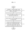
- FIG. 2 is a flowchart illustrating an operating method of the ultrasound diagnosis apparatus of FIG. 1 .
- the ultrasound diagnosis apparatus 100 includes a probe 110, a detector 120, a storage unit 130, and an image processor 140.
- the ultrasound diagnosis apparatus 100 may further include an output unit 150 and an input unit 160.
- the probe 110 may transmit an ultrasound signal to an object 200, and receive a response signal (S110).
- the probe 110 may scan the object 200 through the transmission of the ultrasound signal and the receipt of the response signal.
- the response signal may be a signal that transmits through the object 200 or is reflected by the object 200.
- the object 200 may be an animal body, such as a human body, or a part of an animal body.
- the object 200 may be a fetus or an organ of an animal body.
- the detector 120 acquires a sensor signal including at least one of location information representing a three-dimensional location of the probe 110, and orientation information representing a directivity of the probe 110 on the object 200 (S120).
- the location information may include three-dimensional coordinate values x, y, and z, and the orientation information may include a three-dimensional angle.
- an origin may be an initial location of the probe 110 or the object 200, and in the orientation information, an origin may be the object 200.
- the storage unit 130 may store the sensor signal acquired by the detector 120 associated with the response signal (S130).
- the image processor 140 may form an ultrasound image based on the received response signal, form an image indicator based on the sensor signal stored in the storage unit 130, and form a display image including the ultrasound image and the image indicator corresponding to the ultrasound image (S140).
- the output unit 150 may output the display image.
- the output unit 150 may be a display apparatus or a printer.
- the storage unit 130 may further store a data signal obtained based on the response signal.
- the data signal may be processed by the image processor 140.
- the image processor 140 may form the ultrasound image by using the data signal stored in the storage unit 130, and may form the image indicator by using the sensor signal stored in the storage unit 130.
- the input unit 160 may receive a user input from a user, and may transfer the user input to the image processor 140.
- the user input may include an output request for outputting the data signal stored in the storage unit 130.
- the image processor 140 may form the display image based on the data signal and the sensor signal stored in the storage unit 130.
- FIG. 3 is a diagram showing an example of a display image 300 output to the output unit 150 shown in FIG. 1 .
- the display image 300 output to the output unit 150 may include an ultrasound image 310 and an image indicator 320.
- the ultrasound image 310 and the image indicator 320 are separated from each other; however, the image of FIG. 3 is just an example of the display image 300.
- the image indicator 320 may lie over the ultrasound image 310, unlike the example shown in FIG. 3 .
- FIG. 4 is a diagram showing an example of the image indicator 320 included in the display image 300.
- the image indicator 320 may be a marker representing location information or orientation information of the object 200 by using one or more of an image and a test.
- the image indicator 320 may include a coordinate system consisting of anatomical axes [Cr(cranial)-Ca(caudal), A(anterior)-P(posterior), and R(right)-L(left)], and an arrow 321 may represent the location information or the orientation information.
- the center of the object may be located at the origion O of the coordinate system, and the probe 110 may be located at the end PR of the arraw 321.
- the image indicator 320 may further include text (a, b) representing an angle between the anatomical axis (Cr-Ca, A-P, and R-L) and the probe 110.
- the image indicator 320 may represent the location information or the orientation information of the probe 110 with respect to the object 200 in various ways.
- the detector 120 may detect the location information or the orientation information of the probe 110 during a scanning session in which the probe 110 scans the object 200.
- a three-dimensional location or orientation of the probe 110 may be fixed or may be movable.
- the detector 120 may detect one or more continuous sensor signals.
- the one or more sensor signals may include at least one of the location information and the orientation information of the probe 110.
- the storage unit 130 may store the one or more sensor signals and one or more data signals respectively corresponding to the one or more sensor signals.
- the one or more data signals may be acquired based on the response signal.
- the image processor 140 may acquire one or more display images by using the one or more sensor signals and the one or more data signals stored in the storage unit 130. If there are a plurality of display images, the display images may represent moving pictures. Each of the one or more display images may include an image indicator 320 formed based on a corresponding sensor signal among the one or more sensor signals, and an ultrasound image 310 formed based on a corresponding data signal among the one or more data signals.
- the detector 120 may detect M pieces of location information or M pieces of orientation information during the scanning session.
- M is a positive natural number.
- the sensor signal may include M sensor sub-signals about the M pieces of location information or orientation information.
- Data signals of N frames may be acquired based on the response signal acquired by the probe 110 during the scanning session.
- N is a natural number.
- the data signals may include N frame data signals about the N frames.
- An n-th frame data signal is a signal for outputting an n-th ultrasound image about an n-th frame.
- the n-th frame data signal may include a plurality of pixel values.
- FIG. 5 is a diagram showing an example of relations between the N frame data signals and the M sensor sub-signals.
- each of the N frame data signals FS1, FS2, ..., FSN may correspond to one matching sensor sub-signal among M sensor sub-signals SS1, SS2, ..., SSM.
- Each of the M sensor sub-signals SS1, SS2, ..., SSM may correspond to one or more matching frames among the N frames.
- the N frame data signals FS1, FS2, ..., FSN and the M sensor sub-signals SS1, SS2, ..., SSM may be acquired independently from each other during the scanning session.
- correspondence relations between the N frame data signals FS1, FS2, ..., FSN and the M sensor sub-signals SS1, SS2, ..., SSM may be determined based on times of acquiring the N frame data signals FS1, FS2, ..., FSN and times of acquiring the M sensor sub-signals SS1, SS2, ..., SSM.
- the first frame representing data signal FS1 and the second frame representing data signal FS2 correspond to the first sensor sub-signal SS1. That is, the first sensor sub-signal SS1 is the matching sensor sub-signal for the first frame and for the second frame, and the first and second frames are matching frames of the first sensor sub-signal SS1.
- the N frame data signals FS1, FS2, ..., FSN and the M sensor sub-signals SS1, SS2, ..., SSM correspond to each other in a many-to-one correspondence, where many may mean greater than one.
- FIG. 5 shows only an example of the correspondence relation, and the N frame data signals FS1, FS2, ..., FSN and the M sensor sub-signals may correspond to each other in various manners, for example, a one-to-one correspondence, a many-to-one correspondence, or a one-to-many correspondence.
- FIG. 6 is a diagram showing an example of forming a display image 300A in the image processor 140 shown in FIG. 1 .
- the display image 300A formed by the image processor 140 may include N frame display images 300-1, 300-2,..., 300-N of N frames.
- an n-th frame display image of an n-th frame may include an n-th frame ultrasound image 310-n (not shown) and an n-th frame image indicator 320-n (not shown).
- the storage unit 130 may store the N frame data signals FS1, FS2, ..., FSN and M sensor sub-signals SS1, SS2, ..., SSM.
- the correspondence relation between the N frame data signals FS1, FS2, ..., FSN and the M sensor sub-signals SS1, SS2, ..., SSM is the same as that shown in FIG. 5 .
- the application is not limited to the correspondence shown in FIGS. 5 and 6 , and other examples may have different correspondence.
- the image processor 140 may form an n-th frame ultrasound image 310-n based on the n-th frame data signal FSn stored in the storage unit 130.
- the image processor 140 may form an n-th frame image indicator 320-n based on the matching sensor sub-signal of the n-th frame among the M sensor sub-signals SS1, SS2, ..., SSM stored in the storage unit 130.
- the third frame image indicator 320-3 may be formed based on the second sensor sub-signal SS2, that is, the matching sensor sub-signal of the third frame.
- the storage unit 130 may further store relational information representing the correspondence relation between the N frame data signals FS1, FS2, ..., FSN and the M sensor sub-signals SS1, SS2, ..., SSM.
- FIG. 7 is a diagram showing an example of the storage unit 130 shown in FIG. 1 .
- the storage unit 130 may store the N frame data signals FS1, FS2, ..., FSN included in a data signal FS and the M sensor sub-signals SS1, SS2, ..., SSM included in a sensor signal SS.
- Each of the M sensor sub-signals SS1, SS2, ..., SSM may include sensor information LI1, LI2, ..., LIM and frame information FI1, FI2, ..., FIM.
- the sensor information LI1, LI2, ..., LIM indicates at least one of the location information and the orientation information of the probe 110.
- Each piece of the frame information FI1, FI2, ..., FIM indicates the matching frame of a corresponding sensor sub-signal.
- the frame information FI1 included in the first sensor sub-signal SS1 may indicate the first and second frames.
- FIG. 8 is a diagram showing another example of the storage unit 130 shown in FIG. 1 .
- the storage unit 130 may store the N frame data signals FS1, FS2, ..., FSN, the M sensor sub-signals SS1, SS2, ..., SSM, and an information table ITB indicating relational information FS-SS.
- a method of storing the N frame data signals FS1, FS2, ..., FSN, the M sensor sub-signals SS1, SS2, ..., SSM, and the relational information FS-SS in the storage unit 130 is not limited to the examples shown in FIGS. 7 and 8 .
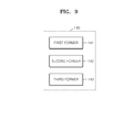
- FIG. 9 is a diagram showing an example of the image processor 140 of FIG. 1 .
- the image processor 140 may include a first former 141, a second former 142, and a third former 143.
- the first former 141 may form an ultrasound image 310 based on the response signal received by probe 110.
- the second former 142 may form an image indicator 320 based on the sensor signal stored in the storage unit 130.
- the third former 143 may form a display image including the ultrasound image 310 and the image indicator 320 corresponding to the ultrasound image 310 (see, FIG. 3 ).
- FIG. 9 is an example of the implementation of the image processor 140.
- each of the first former 141, the second former 142, and the third former 143 is an independent processor.
- the second former 142, and the third former 143 are implemented as one processor.
- the ultrasound diagnosis apparatus and the operating method of the ultrasound diagnosis apparatus may be provided so that the user of the ultrasound diagnosis apparatus may intuitively recognize the state of scanning the object.
- the ultrasound diagnosis apparatus may automatically store the sensor signals including the sensor information indicating the three-dimensional location or orientation of the probe with respect to the object in the storage unit while the probe is scanning the object. Therefore, the user does not need to manipulate the ultrasound diagnosis apparatus while scanning the object, in order to display the image indicator on the ultrasound image. Thus, operating property, efficiency, and productivity may be improved.
- the image indicator is output with the ultrasound image based on the sensor signal stored in the storage unit. Therefore, the user may intuitively recognize the scanning manner of the object through the image indicator.
- the ultrasound diagnosis apparatus and the operating method of the ultrasound diagnosis apparatus may be provided so that the user of the ultrasound diagnosis apparatus may intuitively recognize the state of scanning the object.
- the embodiments of the present disclosure can be written as computer programs and can be implemented in general-use digital computers or computer processors that execute the programs using a non-transitory computer readable recording medium.
- Examples of the computer readable recording medium include magnetic storage media (e.g., ROM, RAM, USB, floppy disks, hard disks, etc.), optical recording media (e.g., CD-ROMs, and DVDs), and PC interfaces (e.g., PCI, PCI-express, Wifi, etc.).
Landscapes
- Life Sciences & Earth Sciences (AREA)
- Health & Medical Sciences (AREA)
- Biomedical Technology (AREA)
- Biophysics (AREA)
- Nuclear Medicine, Radiotherapy & Molecular Imaging (AREA)
- Pathology (AREA)
- Radiology & Medical Imaging (AREA)
- Engineering & Computer Science (AREA)
- Physics & Mathematics (AREA)
- Heart & Thoracic Surgery (AREA)
- Medical Informatics (AREA)
- Molecular Biology (AREA)
- Surgery (AREA)
- Animal Behavior & Ethology (AREA)
- General Health & Medical Sciences (AREA)
- Public Health (AREA)
- Veterinary Medicine (AREA)
- Ultra Sonic Daignosis Equipment (AREA)
Applications Claiming Priority (1)
| Application Number | Priority Date | Filing Date | Title |
|---|---|---|---|
| KR20120031215 | 2012-03-27 |
Publications (1)
| Publication Number | Publication Date |
|---|---|
| EP2644100A1 true EP2644100A1 (de) | 2013-10-02 |
Family
ID=48143052
Family Applications (1)
| Application Number | Title | Priority Date | Filing Date |
|---|---|---|---|
| EP13160621.2A Withdrawn EP2644100A1 (de) | 2012-03-27 | 2013-03-22 | Ultraschall-Diagnosevorrichtung und Betriebsverfahren davon |
Country Status (4)
| Country | Link |
|---|---|
| US (1) | US20130261448A1 (de) |
| EP (1) | EP2644100A1 (de) |
| JP (1) | JP2013202412A (de) |
| KR (1) | KR20130110033A (de) |
Families Citing this family (7)
| Publication number | Priority date | Publication date | Assignee | Title |
|---|---|---|---|---|
| US10667790B2 (en) | 2012-03-26 | 2020-06-02 | Teratech Corporation | Tablet ultrasound system |
| US9877699B2 (en) | 2012-03-26 | 2018-01-30 | Teratech Corporation | Tablet ultrasound system |
| KR20150082945A (ko) * | 2014-01-08 | 2015-07-16 | 삼성메디슨 주식회사 | 초음파 진단 장치 및 그 동작방법 |
| CN105769243B (zh) * | 2016-03-17 | 2018-10-09 | 辽宁石油化工大学 | 一种超声波诊断装置 |
| KR101818726B1 (ko) | 2016-11-14 | 2018-01-18 | 테라셈 주식회사 | 내시경 장치 및 이것의 제어 방법 |
| KR101859717B1 (ko) * | 2016-12-22 | 2018-06-01 | 테라셈 주식회사 | 내시경 장치 및 이것의 제어 방법 |
| CN112155596B (zh) * | 2020-10-10 | 2023-04-07 | 达闼机器人股份有限公司 | 超声波诊断设备、超声波图像的生成方法及存储介质 |
Citations (4)
| Publication number | Priority date | Publication date | Assignee | Title |
|---|---|---|---|---|
| EP1523940A1 (de) * | 2003-10-14 | 2005-04-20 | Aloka Co., Ltd. | Ultraschalldiagnosegerät |
| EP1525850A1 (de) * | 2003-10-22 | 2005-04-27 | Aloka Co. Ltd. | Ultraschalldiagnosegerät |
| WO2009051847A1 (en) * | 2007-10-19 | 2009-04-23 | Calin Caluser | Three dimensional mapping display system for diagnostic ultrasound machines and method |
| EP2213240A1 (de) * | 2009-01-28 | 2010-08-04 | Medison Co., Ltd. | Bildanzeigebereitstellung in einem Ultraschallsystem |
-
2013
- 2013-03-15 KR KR1020130028233A patent/KR20130110033A/ko not_active Ceased
- 2013-03-22 EP EP13160621.2A patent/EP2644100A1/de not_active Withdrawn
- 2013-03-26 JP JP2013064904A patent/JP2013202412A/ja active Pending
- 2013-03-27 US US13/851,697 patent/US20130261448A1/en not_active Abandoned
Patent Citations (4)
| Publication number | Priority date | Publication date | Assignee | Title |
|---|---|---|---|---|
| EP1523940A1 (de) * | 2003-10-14 | 2005-04-20 | Aloka Co., Ltd. | Ultraschalldiagnosegerät |
| EP1525850A1 (de) * | 2003-10-22 | 2005-04-27 | Aloka Co. Ltd. | Ultraschalldiagnosegerät |
| WO2009051847A1 (en) * | 2007-10-19 | 2009-04-23 | Calin Caluser | Three dimensional mapping display system for diagnostic ultrasound machines and method |
| EP2213240A1 (de) * | 2009-01-28 | 2010-08-04 | Medison Co., Ltd. | Bildanzeigebereitstellung in einem Ultraschallsystem |
Also Published As
| Publication number | Publication date |
|---|---|
| JP2013202412A (ja) | 2013-10-07 |
| KR20130110033A (ko) | 2013-10-08 |
| US20130261448A1 (en) | 2013-10-03 |
Similar Documents
| Publication | Publication Date | Title |
|---|---|---|
| EP2644100A1 (de) | Ultraschall-Diagnosevorrichtung und Betriebsverfahren davon | |
| US9314225B2 (en) | Method and apparatus for performing ultrasound imaging | |
| US11521363B2 (en) | Ultrasonic device, and method and system for transforming display of three-dimensional ultrasonic image thereof | |
| JP5685133B2 (ja) | 画像処理装置、画像処理装置の制御方法、およびプログラム | |
| WO2019072827A1 (en) | Intelligent ultrasound-based fertility monitoring | |
| CN106659473A (zh) | 超声成像装置 | |
| US8900147B2 (en) | Performing image process and size measurement upon a three-dimensional ultrasound image in an ultrasound system | |
| US20140371591A1 (en) | Method for automatically detecting mid-sagittal plane by using ultrasound image and apparatus thereof | |
| JP2017502789A (ja) | 超音波撮像システム及び超音波撮像方法 | |
| KR101188593B1 (ko) | 복수의 3차원 초음파 영상을 제공하는 초음파 시스템 및 방법 | |
| CN102596047A (zh) | 超声波诊断装置、控制方法及图像处理装置 | |
| US20200170615A1 (en) | Ultrasound system with extraction of image planes from volume data using touch interaction with an image | |
| JP2021519181A5 (de) | ||
| US12125401B2 (en) | Systems and methods for providing an interactive demonstration of an ultrasound user interface | |
| US20160051220A1 (en) | Ultrasound diagnosis apparatus and ultrasound diagnosis method | |
| US11529124B2 (en) | Artifact removing method and diagnostic apparatus using the same | |
| EP2767237A1 (de) | Automatische Inspektion volumetrischer Bilder | |
| Rocha et al. | Screening of fetal congenital heart disease: the challenge continues | |
| US20140276045A1 (en) | Method and apparatus for processing ultrasound data using scan line information | |
| JP6501796B2 (ja) | 超音波画像のモデル・ベースのセグメンテーションのための取得方位依存特徴 | |
| KR102695456B1 (ko) | 대상체에 관한 횡파 탄성 데이터를 표시하는 초음파 진단 장치 그 동작 방법 | |
| US20120007851A1 (en) | Method for display of images utilizing curved planar reformation techniques | |
| CN110992476B (zh) | 胎儿三维超声图像的3d打印方法、存储介质及超声设备 | |
| CN116763352A (zh) | 子宫内膜蠕动数据处理方法及超声设备 | |
| US20230371931A1 (en) | Ultrasonic diagnostic apparatus and ultrasonic information processing apparatus |
Legal Events
| Date | Code | Title | Description |
|---|---|---|---|
| PUAI | Public reference made under article 153(3) epc to a published international application that has entered the european phase |
Free format text: ORIGINAL CODE: 0009012 |
|
| AK | Designated contracting states |
Kind code of ref document: A1 Designated state(s): AL AT BE BG CH CY CZ DE DK EE ES FI FR GB GR HR HU IE IS IT LI LT LU LV MC MK MT NL NO PL PT RO RS SE SI SK SM TR |
|
| AX | Request for extension of the european patent |
Extension state: BA ME |
|
| 17P | Request for examination filed |
Effective date: 20140318 |
|
| RBV | Designated contracting states (corrected) |
Designated state(s): AL AT BE BG CH CY CZ DE DK EE ES FI FR GB GR HR HU IE IS IT LI LT LU LV MC MK MT NL NO PL PT RO RS SE SI SK SM TR |
|
| 17Q | First examination report despatched |
Effective date: 20151109 |
|
| STAA | Information on the status of an ep patent application or granted ep patent |
Free format text: STATUS: THE APPLICATION IS DEEMED TO BE WITHDRAWN |
|
| 18D | Application deemed to be withdrawn |
Effective date: 20160322 |