EP2644103A1 - Sonde à ultrasons - Google Patents
Sonde à ultrasons Download PDFInfo
- Publication number
- EP2644103A1 EP2644103A1 EP12851965.9A EP12851965A EP2644103A1 EP 2644103 A1 EP2644103 A1 EP 2644103A1 EP 12851965 A EP12851965 A EP 12851965A EP 2644103 A1 EP2644103 A1 EP 2644103A1
- Authority
- EP
- European Patent Office
- Prior art keywords
- end side
- adhesive
- insulation pipe
- ultrasound
- outer circumference
- Prior art date
- Legal status (The legal status is an assumption and is not a legal conclusion. Google has not performed a legal analysis and makes no representation as to the accuracy of the status listed.)
- Granted
Links
Images



Classifications
-
- A—HUMAN NECESSITIES
- A61—MEDICAL OR VETERINARY SCIENCE; HYGIENE
- A61B—DIAGNOSIS; SURGERY; IDENTIFICATION
- A61B8/00—Diagnosis using ultrasonic, sonic or infrasonic waves
- A61B8/44—Constructional features of the ultrasonic, sonic or infrasonic diagnostic device
- A61B8/4444—Constructional features of the ultrasonic, sonic or infrasonic diagnostic device related to the probe
-
- A—HUMAN NECESSITIES
- A61—MEDICAL OR VETERINARY SCIENCE; HYGIENE
- A61B—DIAGNOSIS; SURGERY; IDENTIFICATION
- A61B1/00—Instruments for performing medical examinations of the interior of cavities or tubes of the body by visual or photographical inspection, e.g. endoscopes; Illuminating arrangements therefor
- A61B1/00064—Constructional details of the endoscope body
- A61B1/0011—Manufacturing of endoscope parts
-
- A—HUMAN NECESSITIES
- A61—MEDICAL OR VETERINARY SCIENCE; HYGIENE
- A61B—DIAGNOSIS; SURGERY; IDENTIFICATION
- A61B8/00—Diagnosis using ultrasonic, sonic or infrasonic waves
- A61B8/12—Diagnosis using ultrasonic, sonic or infrasonic waves in body cavities or body tracts, e.g. by using catheters
-
- A—HUMAN NECESSITIES
- A61—MEDICAL OR VETERINARY SCIENCE; HYGIENE
- A61B—DIAGNOSIS; SURGERY; IDENTIFICATION
- A61B8/00—Diagnosis using ultrasonic, sonic or infrasonic waves
- A61B8/44—Constructional features of the ultrasonic, sonic or infrasonic diagnostic device
- A61B8/4444—Constructional features of the ultrasonic, sonic or infrasonic diagnostic device related to the probe
- A61B8/445—Details of catheter construction
-
- A—HUMAN NECESSITIES
- A61—MEDICAL OR VETERINARY SCIENCE; HYGIENE
- A61B—DIAGNOSIS; SURGERY; IDENTIFICATION
- A61B1/00—Instruments for performing medical examinations of the interior of cavities or tubes of the body by visual or photographical inspection, e.g. endoscopes; Illuminating arrangements therefor
- A61B1/00112—Connection or coupling means
- A61B1/00114—Electrical cables in or with an endoscope
Definitions
- the present invention relates to an ultrasound probe provided with an ultrasound transmission/reception portion having an ultrasound transmitting/receiving surface configured to transmit and receive ultrasound and a cable having a distal end electrically connected to the ultrasound transmission/reception portion.
- An ultrasound probe used for obtaining an ultrasound image by transmitting and receiving ultrasound to and from a region to be examined is configured such that an ultrasound transmission/reception portion, which is located at a distal end of the ultrasound probe and which is configured to transmit and receive ultrasound, is connected, through a cable, to a connector which is located at a proximal end of the ultrasound probe and which connects the ultrasound probe to an ultrasound observation apparatus.
- the ultrasound probe has a configuration in which the outer circumference of the cable is covered with an insulation tube, or the like, which is a reinforced insulation member, in order to ensure electrical safety of the cable.
- Japanese Patent Application Laid-Open Publication No. 2009-28109 discloses a configuration in which an ultrasound transmission/reception portion to which a distal end of a cable is electrically connected is provided in a housing having an insulation property on a distal end side of an ultrasound probe, an insulation pipe through which the cable is inserted is fixed in a hole portion which is formed on the housing and from which the cable is extended outside the housing, and a distal end side region of an insulation tube is adhered and fixed with adhesive to an outer circumference of an exposed region of the insulation pipe which is exposed outside the housing.
- the flowing-out of the adhesive can be prevented by increasing a length of the exposed region of the insulation pipe.
- the length of the exposed region of the insulation pipe is increased, there is a problem that also a length of the distal end rigid portion of the insertion portion of the ultrasound endoscope, at which the exposed region is located, is increased.
- the present invention has been achieved in view of the above-described problem, and an object of the present invention is to provide an ultrasound probe configured to be capable of preventing flowing-out of an adhesive for fixing a distal end side region of an insulation tube onto an outer circumference of an exposed region of an insulation pipe exposed from a housing, without increasing a length of the exposed region, while surely ensuring electric safety of a cable by using the insulation pipe and the insulation tube.
- An ultrasound probe includes: an ultrasound transmission/reception portion having an ultrasound transmission/reception surface for transmitting and receiving ultrasound; a cable having a distal end electrically connected to the ultrasound transmission/reception portion; a housing configured to hold the ultrasound transmission/reception portion such that the ultrasound transmission/reception surface is exposed; a hole portion provided to the housing and configured to lead out the cable from inside of the housing; an insulation pipe through which the cable is inserted, the insulation pipe having a distal end side fixed to the hole portion in a state of contacting an inner circumference of the hole portion, and a proximal end side exposed outside the housing; insulation tube configured to cover an outer circumference of an exposed region of the insulation pipe which is exposed from the hole portion and an outer circumference of the cable led out from a proximal end of the insulation pipe; an adhesive configured to adhere the outer circumference of the exposed region of the insulation pipe and a distal end side region of the insulation tube covering the outer circumference of the exposed region; and a liquid dripping prevention portion disposed
- each of the drawings is a pattern diagram, and care should be taken to the fact that the relationship between the thicknesses and widths of the respective members, a ratio of the thickness of a certain member to that of another member, and the like are different from those of the members in actual sizes. It is needless to say that each of the drawings includes a relationship and a ratio of the dimensions which are different from those in other drawings.
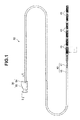
- FIG 1 is a perspective view showing an ultrasound probe according to the present embodiment
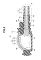
- FIG. 2 is a cross-sectional view of the ultrasound probe along the II-II line in FIG 1
- FIG. 3 is an enlarged cross-sectional view of the region of the ultrasound probe enclosed by the line III in FIG. 2 .
- an ultrasound probe 50 includes an ultrasound transducer cable 40.
- the ultrasound transducer cable 40 has a main part configured by a cable 41 including a plurality of signal lines, and an insulation tube 42 which covers an outer circumference of the cable 41.
- the cable 41 including a plurality of signal lines is bundled into one with the insulation tube 42.
- the insulation tube 42 is made of a heat-shrinkable tube, for example, which is formed by a thin and flexible rubber or the like having voltage endurance, so as to ensure specified voltage endurance of the cable 41, and so as not to impede the flexibility of an insertion portion 2 when an ultrasound probe 50 is provided in an ultrasound endoscope 1 (Regarding these components, see FIG 7 ).
- the insulation tube 42 has a function for preventing the cable 41 from contacting metal members such as a light guide, a balloon conduit, and a forceps channel and the like, not shown, provided in the insertion portion 2, when the ultrasound probe 50 is provided in the ultrasound endoscope 1, to be described later, for example. That is, the insulation tube 42 has a function for insulating the cable 41 from other metal members.
- the cable 41 is exposed. Furthermore, a plurality of connectors 45, which electrically connect the cable 41 to a substrate, not shown, of an ultrasound connector 8 provided in an endoscope connector 5 to be described later, are provided to the exposed region of the cable 41 (regarding these components, see FIG. 7 ).
- the distal end of the ultrasound transducer cable 40 is connected with an ultrasound transducer unit 30.
- the ultrasound transducer unit 30 has a main part configured by including an ultrasound transmission/reception portion 35 having an ultrasound transmission/reception surface 35f configured to transmit and receive ultrasound, and a housing 34 configured to hold the ultrasound transmission/reception portion 35 such that the ultrasound transmission/reception surface 35f is exposed.
- the housing 34 is made of a member having voltage endurance, for example, a resin such as polysulphone, polyimide, or PET, in order to ensure specified voltage endurance of the cable 41.
- the ultrasound transmission/reception portion 35 includes an ultrasound transducer 32, an acoustic lens 31, and a substrate 33, and is disposed in a space 34i located on a distal end side in the housing 34.
- the ultrasound transducer 32 emits ultrasound to a region to be examined through the acoustic lens 31, and after the emission, receives ultrasound reflected back from the region to be examined through the acoustic lens 31 to convert the ultrasound into an electric signal.
- the acoustic lens 31 has a function for collecting the ultrasound emitted from the ultrasound transducer 32 to the region to be examined so as not to diffuse, and emitting the ultrasound. Note that the surface of the acoustic lens 31 configures the ultrasound transmission/reception surface 35f.
- the substrate 33 is electrically connected to the ultrasound transducer 32, and is connected with a distal end 41s of the cable 41, which is not covered with the insulation tube 42, on the distal end side of the ultrasound transducer cable 40.
- the electric signal converted from the ultrasound by the ultrasound transducer 32 is transmitted to the ultrasound transducer cable 40 through the substrate 33.
- a hole portion 34h for leading out the cable 41 having the distal end electrically connected to the substrate 33, from inside of the housing 34 to the outside of the housing 34, is formed on the proximal end side of the housing 34, and the hole portion 34h is formed such that the space 34i inside the housing 34, in which the ultrasound transmission/reception portion 35 is provided, communicates with the proximal end surface 34e of the housing 34.
- a distal end side of the insulation pipe 36 through which the cable 41 is inserted is fixed to the hole portion 34h so as to contact the inner circumference of the hole portion 34h. Note that the proximal end side of the insulation pipe 36 is located so as to be exposed outside the housing 34.
- the insulation pipe 36 is made of a member having voltage endurance, for example, a resin such as polysulphone, polyimide, or PET, and has a function for preventing other metal members from contacting the cable 41, in order to ensure specified voltage endurance of the cable 41.
- a member having voltage endurance for example, a resin such as polysulphone, polyimide, or PET, and has a function for preventing other metal members from contacting the cable 41, in order to ensure specified voltage endurance of the cable 41.
- the distal end side region of the cable 41 more specifically, as shown in FIG. 2 , a region of the cable 41 which is more distal end side than the region inserted into the insulation pipe 36 is not covered with the insulation tube 42. That is, the insulation tube 42 covers the outer circumference of the part of the cable 41 led out rearward from a proximal end 36k of the insulation pipe 36, except for the connectors 45 provided on the proximal end side.
- a distal end side region 42s of the insulation tube 42 covers the outer circumference of an exposed region 36r of the insulation pipe 36, which is exposed from the hole portion 34h, and as shown in FIG. 3 , the distal end side region 42s is adhered and fixed to the outer circumference of the exposed region 36r with an adhesive 52 applied to a distal end side area between the outer circumference of the exposed region 36r and the distal end side region 42s.
- the area where the adhesive 52 is applied on the outer circumference of the exposed region 36r may be so formed as to have a rough surface.
- a sticky member 61 which is a liquid dripping prevention portion that prevents the adhesive 52 from flowing into the insulation tube 42 from the proximal end 36k of the insulation pipe 36 and contacting the cable 41, is provided between the outer circumference of the exposed region 36r and the distal end side region 42s so as to be located at an area which is more proximal end side than the area where the adhesive 52 is applied.
- the sticky member 61 clings to the outer circumference of the exposed region 36r and the distal end side region 42s, and is made of a member having a higher viscosity than the adhesive 52, for example, a member having a viscosity of 2 to 30 N, such as a double-stick tape made of silicone.
- the sticky member 61 just clings to the distal end side region 42s. Therefore, the distal end side region 42s is not damaged by the clinging of the sticky member 61.
- the distal end side region 42s of the insulation tube 42 is adhered and fixed to the outer circumference of the exposed region 36r of the insulation pipe 36 with the adhesive 52, and the sticky member 61 is provided between the outer circumference of the exposed region 36r and the distal end side region 42s so as to be located at the area which is more proximal end side than the area where the adhesive 52 is applied.
- the insulation tube 42 and the insulation pipe 36 which cover the outer circumference of the cable 41 are made of the members having voltage endurance, thereby capable of sufficiently ensuring specified voltage endurance of the cable 41.
- the ultrasound probe 50 having a configuration capable of preventing the adhesive 52, which fixes the distal end side region 42s of the insulation tube 42 to the outer circumference of the exposed region 36r of the insulation pipe 36, from flowing out without increasing the length of the exposed region 36r while surely ensuring the electric safety of the cable 41 using the insulation pipe 36 and the insulation tube 42.
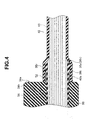
- FIG. 4 is a partial cross-sectional view showing, in an enlarged manner, the vicinity of the proximal end side of the insulation pipe of the ultrasound probe according to the present embodiment.
- the configuration of the ultrasound probe according to the second embodiment is different from that of the ultrasound probe according to the first embodiment shown in the above-described FIGS. 1 to 3 in that, instead of the sticky member, a projection portion, which is provided along the outer circumference of the proximal end of the insulation pipe, is used for the liquid dripping prevention portion. Accordingly, the same components as those in the first embodiment are attached with the same reference numerals and the description thereof will be omitted.
- an outward flange-shaped projection portion 36t as a liquid dripping prevention portion is formed in a circumferential shape along the outer circumference of the proximal end of the exposed region 36r of the insulation pipe 36.
- the projection portion 36t is provided between the outer circumference of the exposed region 36r and the distal end side region 42s so as to be located in the area which is more proximal end side than the area where the adhesive 52 is applied, and contacts the distal end side region 42s of the insulation tube 42.
- the projection portion 36t may be formed as a body separated from the insulation pipe 36, or may be formed integrally with the insulation pipe 36 by causing the outer circumference of the proximal end of the insulation pipe 36 to be bulged.
- the distal end side region 42s of the insulation tube 42 covers the outer circumference of the exposed region 36r of the insulation pipe 36 and is adhered and fixed to the outer circumference of the exposed region 36r with the adhesive 52 applied between the outer circumference of the area, which is more distal end side than the projection portion 36t, of the exposed region 36r and the distal end side region 42s.
- the projection portion 36t is provided between the outer circumference of the exposed region 36r and the distal end side region 42s so as to be located on the more distal end side than the area where the adhesive 52 is applied, and blocks the adhesive 52 which attempts to flow out toward the proximal end side, thereby preventing the adhesive 52 from flowing into the insulation tube 42 from the proximal end 36k of the insulation pipe 36 and contacting the cable 41.
- a tapered surface 36v which inclines toward the cable 41 side from the outer circumference to the inner circumference of the insulation pipe 36, is formed at the proximal end 36k of the insulation pipe 36.
- the tapered surface 36v is formed by cutting off an edge portion of the end face of the outer circumference of the proximal end 36k of the insulation pipe 36, in order to prevent damage on the insulation tube 42 by the edge portion of the end face.
- the distal end side region 42s of the insulation tube 42 is adhered and fixed to the outer circumference of the exposed region 36r of the insulation pipe 36 with the adhesive 52.
- the projection portion 36t formed in a circumferential shape along the outer circumference of the proximal end of the insulation pipe 36 is provided between the outer circumference of the exposed region 36r and the distal end side region 42s so as to be located in the area which is more proximal end side than the area where the adhesive 52 is applied.
- the projection portion 36t blocks the adhesive 52 flowing out toward the proximal end side on the outer circumference of the exposed region 36r, thereby capable of surely preventing the adhesive 52 from flowing into the insulation tube 42 from the proximal end 36k of the insulation pipe 36.
- FIG 5 is a partial cross-sectional view showing, in an enlarged manner, the vicinity of the proximal end side of the insulation pipe of the ultrasound probe according to the present embodiment.
- the configuration of the ultrasound probe according to the third embodiment is different from the ultrasound probe according to the first embodiment shown in the above-described FIGS. 1 to 3 , in that an absorbing member is used for the liquid dripping prevention portion, instead of the sticky member. Accordingly, the components as those in the first embodiment are attached with the same reference numerals, and the description thereof will be omitted.
- an absorbing member 62 as the liquid dripping prevention portion is provided between the outer circumference of the exposed region 36r and the distal end side region 42s so as to be located in the area which is more proximal end side than the region where the adhesive 52 is applied.
- the absorbing member 62 has a function for absorbing the adhesive 52 flown out toward the proximal end side between the outer circumference of the exposed region 36r and the distal end side region 42s, and is made of an adhesive absorbing sheet.
- the adhesive absorbing sheet is a sheet-like porous member which can absorb fluid, and more specifically, a sponge such as polyurethane or polystyrene, or superabsorbent polymer such as sodium polyacrylate is used.
- the distal end side region 42s of the insulation tube 42 covers the outer circumference of the exposed region 36r of the insulation pipe 36, and is adhered and fixed to the outer circumference of the exposed region 36r with the adhesive 52 applied between the outer circumference of the area, which is more distal end side than the absorbing member 62, of the exposed region 36r and the distal end side region 42s.
- the absorbing member 62 is provided between the outer circumference of the exposed region 36r and the distal end side region 42s so as to be located on the more proximal end side than the area where the adhesive 52 is applied.
- the absorbing member absorbs the adhesive 52 which attempts to flow out toward the proximal end side on the outer circumference of the insulation pipe 36, thereby preventing the adhesive 52 from flowing into the insulation tube 42 from the proximal end 36k of the insulation pipe 36 and contacting the cable 41.
- the absorbing member 62 is made of a flexible porous member, as described above, the absorbing member does not cause damage on the insulation tube 42 contacting the absorbing member.
- the distal end side region 42s of the insulation tube 42 is adhered and fixed to the outer circumference of the exposed region 36r of the insulation pipe 36 with the adhesive 52, and the absorbing member 62 is provided between the outer circumference of the exposed region 36r and the distal end side region 42s so as to be located in the area which is more proximal end side than the area where the adhesive 52 is applied.
- the absorbing member 62 absorbs the adhesive 52 flown out toward the proximal end side on the outer circumference of the exposed region 36r, thereby surely preventing the adhesive 52 from flowing into the insulation tube 42 from the proximal end 36k of the insulation pipe 36.
- FIG. 6 is a partial cross-sectional view showing, in an enlarged manner, the vicinity of the proximal end side of the insulation pipe of the ultrasound probe according to the present embodiment.
- the configuration of the ultrasound probe according to the fourth embodiment is different from the ultrasound probe according to the first embodiment shown in the above-described FIGS. 1 to 3 in that a groove formed at the exposed region of the insulation pipe is used as the liquid dripping prevention portion, instead of the sticky member. Therefore, the same components as those in the first embodiment are attached with the same reference numerals and the description thereof will be omitted.
- a groove portion 36m as a liquid dripping prevention portion in which the adhesive 52 is injected is formed on the outer circumference of the exposed region 36r by causing the outer circumference to be dented.
- the groove portion 36m may be formed in a circumferential shape along the outer circumference of the exposed region 36r, or may be partially formed along the outer circumference.
- the groove portion 36m is formed on the exposed region 36r so as to be located in the vicinity of the proximal end surface 34e of the housing 34.
- the groove portion 36m may be formed at any position as along as the position is located on the exposed region 36r.
- the groove portion 36m may be formed in plural numbers on the exposed region 36r so as to be located at positions separated from one another.
- the distal end side region 42s of the insulation tube 42 directly covers the outer circumference of the exposed region 36r of the insulation pipe 36, and is adhered and fixed to the outer circumference of the exposed region 36r with the adhesive 52 injected in the groove portion 36m on the exposed region 36r.
- the groove portion 36m prevents the adhesive 52 from flowing out toward the proximal end side on the outer circumference of the exposed region 36r by the adhesive 52 being injected in the groove portion between the outer circumference of the exposed region 36r and the distal end side region 42s, thereby preventing the adhesive 52 from flowing into the insulation tube 42 from the proximal end 36k of the insulation pipe 36 and contacting the cable 41.
- the distal end side region 42s of the insulation tube 42 is adhered and fixed to the outer circumference of the exposed region 36r of the insulation pipe 36 with the adhesive 52, and the adhesive 52 is injected in the groove portion 36m formed on the outer circumference of the exposed region 36r.
- the ultrasound probe 50 described above in the first to fourth embodiments are used in an ultrasound endoscope, for example.
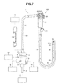
- FIG. 7 is a view showing an ultrasound endoscope apparatus provided with an ultrasound endoscope including ultrasound probe.
- an ultrasound endoscope apparatus 100 includes a main part configured by an ultrasound endoscope 1, a light source device 11, a video processor 12, an ultrasound observation apparatus 14, a suctioning pump 15, and a water-feeding tank 16.
- the ultrasound endoscope 1 includes a main part configured by an elongated insertion portion 2 configured to be inserted into a body, an operation portion 3 provided at a proximal end of the insertion portion 2 and serving also as a grasping portion, a flexible universal cord 4 extended from the operation portion 3, and an endoscope connector 5 provided at an extension end of the universal cord 4.
- the endoscope connector 5 is provided with a light source connector 6, an electric connector 7, an ultrasound connector 8, a suction cap 9, and an air/water feeding mouthpiece 10.
- the light source device 11 that supplies illumination light is configured to be attachable to and detachable from the light source connector 6.
- the video processor 12 that performs various signal processings is configured to be attachable to and detachable from the electric connector 7 through a signal cable, not shown.
- the ultrasound observation apparatus 14 is configured to be attachable to and detachable from the ultrasound connector 8 , through an ultrasound cable 13, the ultrasound connector 8 being electrically connected with the connectors 45 provided on the proximal end side of the cable 41 of the ultrasound transducer cable 40 (regarding these components, see FIG 1 ).
- suctioning pump 15 is configured to be attachable to and detachable from the suction cap 9 through a suction tube, not shown.
- water-feeding tank 16 is attachable to and detachable from the air/water feeding mouthpiece 10 through an air/water feeding tube, not shown.
- the ultrasound observation apparatus 14 controls various operations of the ultrasound endoscope 1, for example, controls driving of the ultrasound transducer 32 and performs operation for generating a video signal by performing signal processing on an electric signal obtained by driving control of the ultrasound transducer 32.
- the video signal generated in the ultrasound observation apparatus 14 is outputted to a display device, not shown. As a result, an ultrasound image is displayed on the screen of the display device which receives the video signal.
- the insertion portion 2 of the ultrasound endoscope 1 includes, in a linked manner, in the following order from the distal end side: a distal end rigid portion 21; a bending portion 22 configured to be bendable in up/down direction and left/right direction, for example; and a flexible tube portion 23 which is long and has flexibility.
- a distal end rigid portion 21 a distal end rigid portion 21
- a bending portion 22 configured to be bendable in up/down direction and left/right direction, for example
- a flexible tube portion 23 which is long and has flexibility.
- the above-described ultrasound transducer unit 30 is located on the more distal end side than the distal end rigid portion 21 and fixed to the distal end rigid portion 21.
- the operation portion 3 is provided with bending operation knobs 25, 26 that perform bending operation of the bending portion 22.
- the video processor 12 performs signal processing on the electric signal transmitted from an image pickup unit, not shown, provided in the distal end rigid portion 21, to thereby generate a standard video signal, and output the video signal to the display device, not shown, to display an endoscopic observation image on the screen of the display device.
- the ultrasound probe 50 according to the above-described first to fourth embodiments is applied to the ultrasound endoscope 1 thus configured, there is no need for increasing the length of the insulation pipe 36 in order to prevent the adhesive 52 from flowing out. Therefore, it is possible to form the distal end rigid portion 21, the length of which is short, which improves the operability.
- the adhesive 52 is prevented from flowing out, it is possible to surely prevent the bending of the bending portion 22 from being interfered with as a result that the adhesive 52 adheres to the region of the cable 41 located in the bending portion 22 and the adhered adhesive 52 is cured.
- the ultrasound probe 50 may be provided in an instrument other than the ultrasound endoscope 1, and also in such a case, it is needless to say that it is possible to obtain the same effects as those in the case where the ultrasound probe 50 is applied to the ultrasound endoscope 1.
Landscapes
- Health & Medical Sciences (AREA)
- Life Sciences & Earth Sciences (AREA)
- Engineering & Computer Science (AREA)
- Surgery (AREA)
- Medical Informatics (AREA)
- Molecular Biology (AREA)
- Radiology & Medical Imaging (AREA)
- Nuclear Medicine, Radiotherapy & Molecular Imaging (AREA)
- Biomedical Technology (AREA)
- Heart & Thoracic Surgery (AREA)
- Physics & Mathematics (AREA)
- Pathology (AREA)
- Biophysics (AREA)
- Animal Behavior & Ethology (AREA)
- General Health & Medical Sciences (AREA)
- Public Health (AREA)
- Veterinary Medicine (AREA)
- Manufacturing & Machinery (AREA)
- Optics & Photonics (AREA)
- Ultra Sonic Daignosis Equipment (AREA)
Applications Claiming Priority (2)
| Application Number | Priority Date | Filing Date | Title |
|---|---|---|---|
| JP2011256430 | 2011-11-24 | ||
| PCT/JP2012/076272 WO2013077101A1 (fr) | 2011-11-24 | 2012-10-11 | Sonde à ultrasons |
Publications (3)
| Publication Number | Publication Date |
|---|---|
| EP2644103A1 true EP2644103A1 (fr) | 2013-10-02 |
| EP2644103A4 EP2644103A4 (fr) | 2013-11-27 |
| EP2644103B1 EP2644103B1 (fr) | 2016-01-13 |
Family
ID=48469556
Family Applications (1)
| Application Number | Title | Priority Date | Filing Date |
|---|---|---|---|
| EP12851965.9A Not-in-force EP2644103B1 (fr) | 2011-11-24 | 2012-10-11 | Sonde à ultrasons |
Country Status (5)
| Country | Link |
|---|---|
| US (1) | US9173636B2 (fr) |
| EP (1) | EP2644103B1 (fr) |
| JP (1) | JP5249481B1 (fr) |
| CN (1) | CN103281966B (fr) |
| WO (1) | WO2013077101A1 (fr) |
Cited By (1)
| Publication number | Priority date | Publication date | Assignee | Title |
|---|---|---|---|---|
| US11903758B2 (en) | 2016-08-04 | 2024-02-20 | Olympus Corporation | Ultrasonic endoscope |
Families Citing this family (7)
| Publication number | Priority date | Publication date | Assignee | Title |
|---|---|---|---|---|
| JP6215806B2 (ja) * | 2014-09-29 | 2017-10-18 | 富士フイルム株式会社 | 内視鏡 |
| WO2016088496A1 (fr) * | 2014-12-01 | 2016-06-09 | オリンパス株式会社 | Endoscope à ultrasons |
| CN107708573B (zh) * | 2015-06-23 | 2020-10-09 | 奥林巴斯株式会社 | 超声波内窥镜 |
| JP6133001B1 (ja) * | 2015-07-13 | 2017-05-24 | オリンパス株式会社 | 超音波振動子モジュールおよび超音波内視鏡 |
| EP3508131A1 (fr) | 2018-01-03 | 2019-07-10 | Koninklijke Philips N.V. | Couplage acoustique de transducteur à ultrasons |
| CN108903972B (zh) * | 2018-06-20 | 2020-12-08 | 青岛大学附属医院 | 一种医用超声波探头用单边补充装置 |
| CN114376601B (zh) * | 2020-10-22 | 2024-11-12 | 佳能医疗系统株式会社 | 超声波探头 |
Family Cites Families (9)
| Publication number | Priority date | Publication date | Assignee | Title |
|---|---|---|---|---|
| US4815471A (en) * | 1988-08-01 | 1989-03-28 | Precision Interconnect Corporation | Catheter assembly |
| US5176140A (en) * | 1989-08-14 | 1993-01-05 | Olympus Optical Co., Ltd. | Ultrasonic probe |
| JP3535204B2 (ja) * | 1994-02-28 | 2004-06-07 | 株式会社東芝 | 超音波プローブ及びその製造方法 |
| JPH0838495A (ja) * | 1994-07-29 | 1996-02-13 | Olympus Optical Co Ltd | 内視鏡用処置具 |
| JP3525700B2 (ja) * | 1997-09-24 | 2004-05-10 | 富士写真光機株式会社 | 超音波プローブ |
| JP4420696B2 (ja) * | 2004-02-26 | 2010-02-24 | Hoya株式会社 | 電子内視鏡の同軸コネクタ |
| JP2006141638A (ja) * | 2004-11-18 | 2006-06-08 | Olympus Corp | 超音波診断用カプセル |
| EP2340768B1 (fr) * | 2005-02-07 | 2015-12-23 | Olympus Corporation | Endoscope a ultrasons |
| JP2009028109A (ja) | 2007-07-25 | 2009-02-12 | Olympus Medical Systems Corp | 超音波内視鏡 |
-
2012
- 2012-10-11 WO PCT/JP2012/076272 patent/WO2013077101A1/fr not_active Ceased
- 2012-10-11 CN CN201280004281.7A patent/CN103281966B/zh not_active Expired - Fee Related
- 2012-10-11 EP EP12851965.9A patent/EP2644103B1/fr not_active Not-in-force
- 2012-10-11 JP JP2013506401A patent/JP5249481B1/ja active Active
-
2013
- 2013-02-15 US US13/768,405 patent/US9173636B2/en active Active
Cited By (1)
| Publication number | Priority date | Publication date | Assignee | Title |
|---|---|---|---|---|
| US11903758B2 (en) | 2016-08-04 | 2024-02-20 | Olympus Corporation | Ultrasonic endoscope |
Also Published As
| Publication number | Publication date |
|---|---|
| US20130204140A1 (en) | 2013-08-08 |
| EP2644103A4 (fr) | 2013-11-27 |
| CN103281966B (zh) | 2015-09-16 |
| JP5249481B1 (ja) | 2013-07-31 |
| CN103281966A (zh) | 2013-09-04 |
| US9173636B2 (en) | 2015-11-03 |
| JPWO2013077101A1 (ja) | 2015-04-27 |
| WO2013077101A1 (fr) | 2013-05-30 |
| EP2644103B1 (fr) | 2016-01-13 |
Similar Documents
| Publication | Publication Date | Title |
|---|---|---|
| US9173636B2 (en) | Ultrasound probe | |
| CN103037750B (zh) | 内窥镜 | |
| US9050052B2 (en) | Ultrasound endoscope | |
| EP2596753B1 (fr) | Endoscope ultrasonore | |
| US20200187765A1 (en) | Insertion portion of endoscope and endoscope to which the insertion portion is applied | |
| CN105163668A (zh) | 超声波内窥镜 | |
| US20180185004A1 (en) | Endoscope connector | |
| JP6013648B1 (ja) | 超音波内視鏡 | |
| US20220361846A1 (en) | Ultrasound endoscope | |
| WO2019102679A1 (fr) | Extrémité d'endoscope et endoscope | |
| JP3586180B2 (ja) | 内視鏡形状検出プローブ | |
| WO2014010283A1 (fr) | Endoscope ultrasonore | |
| CN116687321A (zh) | 内窥镜 | |
| JP3826053B2 (ja) | 内視鏡 | |
| EP3195808A1 (fr) | Endoscope à ultrasons et dispositif d'observation à ultrasons | |
| JP4363956B2 (ja) | 超音波内視鏡 | |
| US12446853B2 (en) | Ultrasonic endoscope | |
| JP2003325527A (ja) | 超音波内視鏡の先端部 | |
| JP2009089925A (ja) | 内視鏡 | |
| JP2025130999A (ja) | 超音波内視鏡 | |
| JP2005312829A (ja) | 内視鏡用照明装置及びこれを適用する内視鏡 | |
| JP2005131128A (ja) | 超音波内視鏡 |
Legal Events
| Date | Code | Title | Description |
|---|---|---|---|
| PUAI | Public reference made under article 153(3) epc to a published international application that has entered the european phase |
Free format text: ORIGINAL CODE: 0009012 |
|
| 17P | Request for examination filed |
Effective date: 20130618 |
|
| AK | Designated contracting states |
Kind code of ref document: A1 Designated state(s): AL AT BE BG CH CY CZ DE DK EE ES FI FR GB GR HR HU IE IS IT LI LT LU LV MC MK MT NL NO PL PT RO RS SE SI SK SM TR |
|
| A4 | Supplementary search report drawn up and despatched |
Effective date: 20131028 |
|
| RIC1 | Information provided on ipc code assigned before grant |
Ipc: A61B 8/12 20060101AFI20131022BHEP Ipc: A61B 1/00 20060101ALI20131022BHEP Ipc: A61B 8/00 20060101ALI20131022BHEP |
|
| 17Q | First examination report despatched |
Effective date: 20140715 |
|
| DAX | Request for extension of the european patent (deleted) | ||
| GRAP | Despatch of communication of intention to grant a patent |
Free format text: ORIGINAL CODE: EPIDOSNIGR1 |
|
| INTG | Intention to grant announced |
Effective date: 20150721 |
|
| RAP1 | Party data changed (applicant data changed or rights of an application transferred) |
Owner name: OLYMPUS CORPORATION |
|
| GRAS | Grant fee paid |
Free format text: ORIGINAL CODE: EPIDOSNIGR3 |
|
| GRAA | (expected) grant |
Free format text: ORIGINAL CODE: 0009210 |
|
| AK | Designated contracting states |
Kind code of ref document: B1 Designated state(s): AL AT BE BG CH CY CZ DE DK EE ES FI FR GB GR HR HU IE IS IT LI LT LU LV MC MK MT NL NO PL PT RO RS SE SI SK SM TR |
|
| REG | Reference to a national code |
Ref country code: GB Ref legal event code: FG4D |
|
| REG | Reference to a national code |
Ref country code: CH Ref legal event code: EP |
|
| REG | Reference to a national code |
Ref country code: IE Ref legal event code: FG4D |
|
| REG | Reference to a national code |
Ref country code: AT Ref legal event code: REF Ref document number: 769953 Country of ref document: AT Kind code of ref document: T Effective date: 20160215 |
|
| REG | Reference to a national code |
Ref country code: DE Ref legal event code: R096 Ref document number: 602012014013 Country of ref document: DE |
|
| REG | Reference to a national code |
Ref country code: LT Ref legal event code: MG4D |
|
| REG | Reference to a national code |
Ref country code: NL Ref legal event code: MP Effective date: 20160113 |
|
| REG | Reference to a national code |
Ref country code: AT Ref legal event code: MK05 Ref document number: 769953 Country of ref document: AT Kind code of ref document: T Effective date: 20160113 |
|
| PG25 | Lapsed in a contracting state [announced via postgrant information from national office to epo] |
Ref country code: NL Free format text: LAPSE BECAUSE OF FAILURE TO SUBMIT A TRANSLATION OF THE DESCRIPTION OR TO PAY THE FEE WITHIN THE PRESCRIBED TIME-LIMIT Effective date: 20160113 |
|
| PG25 | Lapsed in a contracting state [announced via postgrant information from national office to epo] |
Ref country code: GR Free format text: LAPSE BECAUSE OF FAILURE TO SUBMIT A TRANSLATION OF THE DESCRIPTION OR TO PAY THE FEE WITHIN THE PRESCRIBED TIME-LIMIT Effective date: 20160414 Ref country code: NO Free format text: LAPSE BECAUSE OF FAILURE TO SUBMIT A TRANSLATION OF THE DESCRIPTION OR TO PAY THE FEE WITHIN THE PRESCRIBED TIME-LIMIT Effective date: 20160413 Ref country code: HR Free format text: LAPSE BECAUSE OF FAILURE TO SUBMIT A TRANSLATION OF THE DESCRIPTION OR TO PAY THE FEE WITHIN THE PRESCRIBED TIME-LIMIT Effective date: 20160113 Ref country code: FI Free format text: LAPSE BECAUSE OF FAILURE TO SUBMIT A TRANSLATION OF THE DESCRIPTION OR TO PAY THE FEE WITHIN THE PRESCRIBED TIME-LIMIT Effective date: 20160113 Ref country code: IT Free format text: LAPSE BECAUSE OF FAILURE TO SUBMIT A TRANSLATION OF THE DESCRIPTION OR TO PAY THE FEE WITHIN THE PRESCRIBED TIME-LIMIT Effective date: 20160113 Ref country code: ES Free format text: LAPSE BECAUSE OF FAILURE TO SUBMIT A TRANSLATION OF THE DESCRIPTION OR TO PAY THE FEE WITHIN THE PRESCRIBED TIME-LIMIT Effective date: 20160113 |
|
| PG25 | Lapsed in a contracting state [announced via postgrant information from national office to epo] |
Ref country code: AT Free format text: LAPSE BECAUSE OF FAILURE TO SUBMIT A TRANSLATION OF THE DESCRIPTION OR TO PAY THE FEE WITHIN THE PRESCRIBED TIME-LIMIT Effective date: 20160113 Ref country code: LV Free format text: LAPSE BECAUSE OF FAILURE TO SUBMIT A TRANSLATION OF THE DESCRIPTION OR TO PAY THE FEE WITHIN THE PRESCRIBED TIME-LIMIT Effective date: 20160113 Ref country code: LT Free format text: LAPSE BECAUSE OF FAILURE TO SUBMIT A TRANSLATION OF THE DESCRIPTION OR TO PAY THE FEE WITHIN THE PRESCRIBED TIME-LIMIT Effective date: 20160113 Ref country code: PT Free format text: LAPSE BECAUSE OF FAILURE TO SUBMIT A TRANSLATION OF THE DESCRIPTION OR TO PAY THE FEE WITHIN THE PRESCRIBED TIME-LIMIT Effective date: 20160513 Ref country code: RS Free format text: LAPSE BECAUSE OF FAILURE TO SUBMIT A TRANSLATION OF THE DESCRIPTION OR TO PAY THE FEE WITHIN THE PRESCRIBED TIME-LIMIT Effective date: 20160113 Ref country code: SE Free format text: LAPSE BECAUSE OF FAILURE TO SUBMIT A TRANSLATION OF THE DESCRIPTION OR TO PAY THE FEE WITHIN THE PRESCRIBED TIME-LIMIT Effective date: 20160113 Ref country code: IS Free format text: LAPSE BECAUSE OF FAILURE TO SUBMIT A TRANSLATION OF THE DESCRIPTION OR TO PAY THE FEE WITHIN THE PRESCRIBED TIME-LIMIT Effective date: 20160513 Ref country code: PL Free format text: LAPSE BECAUSE OF FAILURE TO SUBMIT A TRANSLATION OF THE DESCRIPTION OR TO PAY THE FEE WITHIN THE PRESCRIBED TIME-LIMIT Effective date: 20160113 |
|
| RAP2 | Party data changed (patent owner data changed or rights of a patent transferred) |
Owner name: OLYMPUS CORPORATION |
|
| RAP2 | Party data changed (patent owner data changed or rights of a patent transferred) |
Owner name: OLYMPUS CORPORATION |
|
| REG | Reference to a national code |
Ref country code: DE Ref legal event code: R097 Ref document number: 602012014013 Country of ref document: DE |
|
| PG25 | Lapsed in a contracting state [announced via postgrant information from national office to epo] |
Ref country code: EE Free format text: LAPSE BECAUSE OF FAILURE TO SUBMIT A TRANSLATION OF THE DESCRIPTION OR TO PAY THE FEE WITHIN THE PRESCRIBED TIME-LIMIT Effective date: 20160113 Ref country code: DK Free format text: LAPSE BECAUSE OF FAILURE TO SUBMIT A TRANSLATION OF THE DESCRIPTION OR TO PAY THE FEE WITHIN THE PRESCRIBED TIME-LIMIT Effective date: 20160113 |
|
| RIN2 | Information on inventor provided after grant (corrected) |
Inventor name: IRIE, KEI |
|
| PLBE | No opposition filed within time limit |
Free format text: ORIGINAL CODE: 0009261 |
|
| STAA | Information on the status of an ep patent application or granted ep patent |
Free format text: STATUS: NO OPPOSITION FILED WITHIN TIME LIMIT |
|
| PG25 | Lapsed in a contracting state [announced via postgrant information from national office to epo] |
Ref country code: RO Free format text: LAPSE BECAUSE OF FAILURE TO SUBMIT A TRANSLATION OF THE DESCRIPTION OR TO PAY THE FEE WITHIN THE PRESCRIBED TIME-LIMIT Effective date: 20160113 Ref country code: CZ Free format text: LAPSE BECAUSE OF FAILURE TO SUBMIT A TRANSLATION OF THE DESCRIPTION OR TO PAY THE FEE WITHIN THE PRESCRIBED TIME-LIMIT Effective date: 20160113 Ref country code: SK Free format text: LAPSE BECAUSE OF FAILURE TO SUBMIT A TRANSLATION OF THE DESCRIPTION OR TO PAY THE FEE WITHIN THE PRESCRIBED TIME-LIMIT Effective date: 20160113 Ref country code: SM Free format text: LAPSE BECAUSE OF FAILURE TO SUBMIT A TRANSLATION OF THE DESCRIPTION OR TO PAY THE FEE WITHIN THE PRESCRIBED TIME-LIMIT Effective date: 20160113 |
|
| 26N | No opposition filed |
Effective date: 20161014 |
|
| PG25 | Lapsed in a contracting state [announced via postgrant information from national office to epo] |
Ref country code: BE Free format text: LAPSE BECAUSE OF FAILURE TO SUBMIT A TRANSLATION OF THE DESCRIPTION OR TO PAY THE FEE WITHIN THE PRESCRIBED TIME-LIMIT Effective date: 20160113 |
|
| PG25 | Lapsed in a contracting state [announced via postgrant information from national office to epo] |
Ref country code: SI Free format text: LAPSE BECAUSE OF FAILURE TO SUBMIT A TRANSLATION OF THE DESCRIPTION OR TO PAY THE FEE WITHIN THE PRESCRIBED TIME-LIMIT Effective date: 20160113 Ref country code: BG Free format text: LAPSE BECAUSE OF FAILURE TO SUBMIT A TRANSLATION OF THE DESCRIPTION OR TO PAY THE FEE WITHIN THE PRESCRIBED TIME-LIMIT Effective date: 20160413 |
|
| REG | Reference to a national code |
Ref country code: CH Ref legal event code: PL |
|
| GBPC | Gb: european patent ceased through non-payment of renewal fee |
Effective date: 20161011 |
|
| REG | Reference to a national code |
Ref country code: IE Ref legal event code: MM4A |
|
| REG | Reference to a national code |
Ref country code: FR Ref legal event code: ST Effective date: 20170630 |
|
| PG25 | Lapsed in a contracting state [announced via postgrant information from national office to epo] |
Ref country code: GB Free format text: LAPSE BECAUSE OF NON-PAYMENT OF DUE FEES Effective date: 20161011 Ref country code: LI Free format text: LAPSE BECAUSE OF NON-PAYMENT OF DUE FEES Effective date: 20161031 Ref country code: CH Free format text: LAPSE BECAUSE OF NON-PAYMENT OF DUE FEES Effective date: 20161031 Ref country code: FR Free format text: LAPSE BECAUSE OF NON-PAYMENT OF DUE FEES Effective date: 20161102 |
|
| PG25 | Lapsed in a contracting state [announced via postgrant information from national office to epo] |
Ref country code: LU Free format text: LAPSE BECAUSE OF NON-PAYMENT OF DUE FEES Effective date: 20161011 |
|
| PG25 | Lapsed in a contracting state [announced via postgrant information from national office to epo] |
Ref country code: IE Free format text: LAPSE BECAUSE OF NON-PAYMENT OF DUE FEES Effective date: 20161011 |
|
| PG25 | Lapsed in a contracting state [announced via postgrant information from national office to epo] |
Ref country code: HU Free format text: LAPSE BECAUSE OF FAILURE TO SUBMIT A TRANSLATION OF THE DESCRIPTION OR TO PAY THE FEE WITHIN THE PRESCRIBED TIME-LIMIT; INVALID AB INITIO Effective date: 20121011 Ref country code: CY Free format text: LAPSE BECAUSE OF FAILURE TO SUBMIT A TRANSLATION OF THE DESCRIPTION OR TO PAY THE FEE WITHIN THE PRESCRIBED TIME-LIMIT Effective date: 20160113 |
|
| PG25 | Lapsed in a contracting state [announced via postgrant information from national office to epo] |
Ref country code: MK Free format text: LAPSE BECAUSE OF FAILURE TO SUBMIT A TRANSLATION OF THE DESCRIPTION OR TO PAY THE FEE WITHIN THE PRESCRIBED TIME-LIMIT Effective date: 20160113 Ref country code: MC Free format text: LAPSE BECAUSE OF FAILURE TO SUBMIT A TRANSLATION OF THE DESCRIPTION OR TO PAY THE FEE WITHIN THE PRESCRIBED TIME-LIMIT Effective date: 20160113 Ref country code: MT Free format text: LAPSE BECAUSE OF NON-PAYMENT OF DUE FEES Effective date: 20161031 |
|
| PG25 | Lapsed in a contracting state [announced via postgrant information from national office to epo] |
Ref country code: AL Free format text: LAPSE BECAUSE OF FAILURE TO SUBMIT A TRANSLATION OF THE DESCRIPTION OR TO PAY THE FEE WITHIN THE PRESCRIBED TIME-LIMIT Effective date: 20160113 Ref country code: TR Free format text: LAPSE BECAUSE OF FAILURE TO SUBMIT A TRANSLATION OF THE DESCRIPTION OR TO PAY THE FEE WITHIN THE PRESCRIBED TIME-LIMIT Effective date: 20160113 |
|
| PGFP | Annual fee paid to national office [announced via postgrant information from national office to epo] |
Ref country code: DE Payment date: 20221019 Year of fee payment: 11 |
|
| P01 | Opt-out of the competence of the unified patent court (upc) registered |
Effective date: 20230528 |
|
| REG | Reference to a national code |
Ref country code: DE Ref legal event code: R119 Ref document number: 602012014013 Country of ref document: DE |
|
| PG25 | Lapsed in a contracting state [announced via postgrant information from national office to epo] |
Ref country code: DE Free format text: LAPSE BECAUSE OF NON-PAYMENT OF DUE FEES Effective date: 20240501 |