EP2644232A1 - Chariot de golf à commande intuitive et roues d'un nouveau type - Google Patents
Chariot de golf à commande intuitive et roues d'un nouveau type Download PDFInfo
- Publication number
- EP2644232A1 EP2644232A1 EP13162023.9A EP13162023A EP2644232A1 EP 2644232 A1 EP2644232 A1 EP 2644232A1 EP 13162023 A EP13162023 A EP 13162023A EP 2644232 A1 EP2644232 A1 EP 2644232A1
- Authority
- EP
- European Patent Office
- Prior art keywords
- handle
- signal
- golf cart
- drives
- signal sensor
- Prior art date
- Legal status (The legal status is an assumption and is not a legal conclusion. Google has not performed a legal analysis and makes no representation as to the accuracy of the status listed.)
- Granted
Links
Images


Classifications
-
- A—HUMAN NECESSITIES
- A63—SPORTS; GAMES; AMUSEMENTS
- A63B—APPARATUS FOR PHYSICAL TRAINING, GYMNASTICS, SWIMMING, CLIMBING, OR FENCING; BALL GAMES; TRAINING EQUIPMENT
- A63B55/00—Bags for golf clubs; Stands for golf clubs for use on the course; Wheeled carriers specially adapted for golf bags
- A63B55/60—Wheeled carriers specially adapted for golf bags
- A63B55/61—Wheeled carriers specially adapted for golf bags motorised
-
- A—HUMAN NECESSITIES
- A63—SPORTS; GAMES; AMUSEMENTS
- A63B—APPARATUS FOR PHYSICAL TRAINING, GYMNASTICS, SWIMMING, CLIMBING, OR FENCING; BALL GAMES; TRAINING EQUIPMENT
- A63B2220/00—Measuring of physical parameters relating to sporting activity
- A63B2220/80—Special sensors, transducers or devices therefor
- A63B2220/83—Special sensors, transducers or devices therefor characterised by the position of the sensor
- A63B2220/833—Sensors arranged on the exercise apparatus or sports implement
-
- A—HUMAN NECESSITIES
- A63—SPORTS; GAMES; AMUSEMENTS
- A63B—APPARATUS FOR PHYSICAL TRAINING, GYMNASTICS, SWIMMING, CLIMBING, OR FENCING; BALL GAMES; TRAINING EQUIPMENT
- A63B2225/00—Miscellaneous features of sport apparatus, devices or equipment
- A63B2225/50—Wireless data transmission, e.g. by radio transmitters or telemetry
- A63B2225/54—Transponders, e.g. RFID
-
- A—HUMAN NECESSITIES
- A63—SPORTS; GAMES; AMUSEMENTS
- A63B—APPARATUS FOR PHYSICAL TRAINING, GYMNASTICS, SWIMMING, CLIMBING, OR FENCING; BALL GAMES; TRAINING EQUIPMENT
- A63B2225/00—Miscellaneous features of sport apparatus, devices or equipment
- A63B2225/72—Means preventing unauthorised use, e.g. by lowering a tennis net
Definitions
- the present invention relates to a independently movable in a direction of travel golf cart (hereinafter also referred to as “trolley” or caddy ”) with a frame, wheels, an energy storage, at least two drives and a controller.
- the document DE 203 07 742 U1 discloses a trolley for carrying a golf bag.
- the trolley has a linkage comprising an upper part and a lower part, which are connected by a hinge.
- a linkage comprising an upper part and a lower part, which are connected by a hinge.
- In the middle of the upper part of the linkage means for controlling a motor is arranged. It is a rotary handle, with which the engine can be switched to forward or reverse operation and with which a respective speed of the trolley can be regulated.
- the document DE 20 2007 005 290 U1 reveals a golf caddy.
- the Caddy has a steering switching device, which consists of two manually operated steering switches. These are each designed as a key switch, so that they automatically return to their inoperative switching position after a press of their push buttons again.
- the steering switches can be assigned via a microprocessor, which is located in a control module and is part of the control module, each specific rotational speed differences of two drive motors, each corresponding to a turning radius, which is driven by the Caddy. Furthermore, proportional switches in the form of strain gauges are disclosed.
- US 3,976,151 A discloses a self propelled golf cart that has means to automatically follow a golfer.
- a self-propelled traveling cart comprising: a frame; at least three wheels; an energy store; at least two drives integrated into the frame, each of the drives coupled to another of the wheels, with driven wheels preferably opposite to the direction of travel; and a controller for the drives.
- the frame comprises a tube and a handle, the handle being rotatably mounted about an axis of the tube; wherein the controller is at least partially integrated in the handle and wherein the controller comprises a signal transmitter, a Signal sensor and an evaluation unit, wherein the signal transmitter / signal sensor is firmly connected to the handle and the signal sensor / signal transmitter is firmly connected to the tube; wherein the signal sensor is adapted to detect rotational movements of the signal generator relative to the signal sensor and to send as an input signal to the evaluation unit; and wherein the evaluation unit is connected to the signal sensor and the drives to convert the input signals into control signals for the drives.
- the controller is at least partially integrated in the handle and wherein the controller comprises a signal transmitter, a Signal sensor and an evaluation unit, wherein the signal transmitter / signal sensor is firmly connected to the handle and the signal sensor / signal transmitter is firmly connected to the tube; wherein the signal sensor is adapted to detect rotational movements of the signal generator relative to the signal sensor and to send as an input signal to the evaluation unit; and wherein
- an autonomously movable in a direction of travel golf cart comprising: a frame; at least three wheels; an energy store; at least two drives integrated into the frame, each of the drives coupled to another of the wheels, with driven wheels preferably opposite to the direction of travel; and a controller for the drives, wherein the frame comprises a tube and a handle, wherein the handle is movably mounted on the tube; wherein the controller is at least partially integrated into the handle and wherein the controller comprises a signal generator, a signal sensor and an evaluation unit, wherein the signal transmitter is arranged at a distance from the signal generator; wherein the signal transmitter is fixedly connected to the handle and the signal sensor is firmly connected to the tube, or wherein the signal sensor is firmly connected to the handle and the signal transmitter fixed to the tube and wherein the signal transmitter and the signal sensor magnetic, inductive, capacitive or optical interact with each other via a corresponding field; wherein the signal sensor is adapted to detect movements of the signal transmitter relative to the signal sensor and to send as
- the handle is coaxial with one end of the tube.
- the handle is additionally mounted axially displaceable relative to the tube or mounted tiltably relative to the tube.
- the signal sensor is adapted to detect rotational and translational movements of the signal generator relative to the signal sensor or rotational and tilting movements of the signal generator and to send to the evaluation unit.
- the signal transmitter and the signal sensor interact inductively, capacitively or optically with one another.
- a range-dependent RFID receiver which is preferably integrated into the handle and communicates with the evaluation unit, and a Radio Frequency IDentification (RFID) transmitter are provided which a user of the car carries with him, preferably in the Area of his hand, with which the user steers the car, wherein the evaluation unit is arranged to issue control signals only when the RFID transmitter and the RFID receiver are sufficiently close relative to each other.
- RFID Radio Frequency IDentification
- the drive can have a position sensor in order to be able to transmit position signals to the evaluation unit, from which an inclination or a gradient of the terrain can be derived, on which the carriage is located.
- a sense of rotation and a rotational intensity of the handle with the signal sensor can be detected.
- the frame has one or more longitudinal tubes, which extend substantially parallel to the direction of travel, and one or more transverse tubes, which extend substantially perpendicular to the direction of travel, wherein the drives are integrated in the transverse tubes and the Handle coupled to one of the longitudinal or the transverse tubes.
- an independently movable in a direction of travel golf cart comprising: a frame; at least three wheels; an energy store; at least two drives in the frame are integrated, wherein each of the drives is coupled to another of the wheels, wherein the driven wheels are preferably opposite to the direction of travel; and a controller for the drives; each wheel comprising: a rim base, a plurality of, in particular three, spokes, a wheel hub and a corresponding plurality of spoke pins each connecting the rim well to the wheel hub via one of the spokes, the rim well having a hollow cylindrical body with an inner and an outer circumferential surface, extending axially along an axis of rotation, the hub being coaxial with the axis of rotation, each spoke pin having a bolt head, the outer shroud having for each of the spokes a radially oriented recess adapted to receive one of the bolt heads, each spoke Has at least one passage opening.
- the wheel also has fixing and centering pins.
- the wheel hub has a hollow cylindrical body, in the outer circumferential surface of openings for non-positive and / or positive reception of the spoke pins are provided.
- each of the spoke pins has a thread.
- depressions receive the bolt heads in a form-fitting manner.
- Fig. 1 shows a perspective view of a golf cart 10, which will also be referred to as "carriage” 10 hereinafter.
- the carriage 10 is used for Transporting a golf bag in which a plurality of golf clubs is stored.
- the cart 10 is powered by a motor so that a user's physical effort to move his bag from one location to another is significantly reduced.
- the carriage 10 has a frame or frame 12 and wheels 14.
- the carriage 10 has, for example, three wheels 14, namely a front wheel 16 and two rear wheels 18.
- the rear wheels 18 are rotatably mounted coaxially about a common axis of construction and rotation (eg Y-axis) extending along a transverse direction of the carriage 10. It is understood that the carriage 10 may also have more than three wheels 14.
- the frame 12 has a plurality of tubes 20 and 22, such as longitudinal tubes 20 and cross tubes 22.
- a first longitudinal tube 20-1 and two transverse tubes 22-1 and 22-2 define an eg T-shaped base of the frame.
- the transverse tubes 22-1 and 22-2 are arranged coaxially with the axis of rotation of the rear wheels 18.
- the longitudinal tube 20-1 is preferably oriented perpendicular to the transverse direction.
- the wheels 14 are rotatably mounted.
- the rear wheels 18 are driven, wherein the front wheel 16 can be mounted loosely rotating.
- the tubes 20-1, 22-1 and 22-2 can meet in a common point of intersection of the T-shaped base and are connected to each other, eg welded or glued. From this point of intersection may further extend another longitudinal tube 20-2 which rises at an angle ⁇ with respect to a horizontal plane (XY plane) in which the T-shaped base lies.
- the second longitudinal tube 20-2 has a preferably horizontally oriented (free) end 24, where a (hand) handle 26 is movably mounted.
- the frame 12 has the tubes 20 and 22 and the handle 26.
- the handle 26 may be rotatably mounted about an axis of rotation 28 (parallel to the X-axis) relative to the end 24 of the second longitudinal tube 20-2.
- the handle 26 can be rotated clockwise or counterclockwise. A corresponding rotational movement is indicated by an arrow 30. Turning the handle 26 clockwise, the carriage 10 moves to the right (R). If the handle 26 is turned counterclockwise, the carriage 10 moves to the left (L).
- the handle 26 may be compared to the longitudinal tube 20-2 additionally axially, that is displaceably mounted in the X direction, as it is by a Arrow 32 is indicated.
- the handle 26 can also be tilted about another axis of rotation 28 '(parallel to the Z-axis) relative to the second longitudinal tube 20-2 to initiate travel of the carriage 10 to the left or right (see arrow 30').
- the alternative axis of rotation 28 ' is preferably perpendicular to the plane in which the T-shaped base of the frame 12 is disposed.
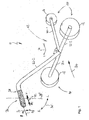
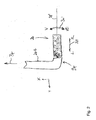
- FIG. 2 is a modification of the car 10 of Fig. 1 shown, which is reflected in particular in the area of the handle 26.
- the handle 26 or its longitudinal axis, which is not described here, is oriented perpendicular to the travel direction 34 (X-direction) or to the main extension direction of the longitudinal tubes 20-1 and 20-2.
- Driving commands "left-hand drive” and “right-hand drive” can be effected by axial displacement, ie movement in the Y-direction, of the handle 26 relative to the end 24 of the longitudinal tube 20-2 (see arrow 32 '), the axial displacement being along an axis of rotation 28 ", which in turn is required for a" forward drive “and a” reverse drive.
- a rotation of the handle 26 about the rotation axis 28" (Y-axis) in this variant causes a drive forwards (V) or back (Z).
- the grip 26 for the "left-hand or right-hand drive” can also be rotatably mounted about an axis of rotation 28 ".
- the axis of rotation 28 '" is perpendicular to the plane of the drawing Fig. 2 ie oriented parallel to the Z direction.
- a clockwise rotation causes a drive to the right and a counterclockwise rotation to drive to the left as the carriage 10 advances.
- the forward travel is also caused in this case by a rotation about the axis 28 '.
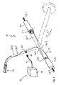
- Fig. 3 shows an interior of the car 10 the Fig. 1 wherein the rear wheels 18 are not shown.
- the output shafts 42-1 and 42-2 are in turn aligned coaxially to the construction axis along the transverse direction.
- the wheels 18 are not shown sitting in the assembled state of the carriage 10 on the output shafts 42-1 and 42-2.
- the drives 40 may, for example, be realized by electric motors.
- the drives 40 may each be connected to an (optional) position sensor 44.
- the attitude sensor 44 can be used to determine whether the carriage 10 is oriented inclined to the horizontal (uphill, downhill, also in combination with yawing, etc).
- the position sensors 44 may also be arranged at locations other than the drives 40. It is advisable to calibrate the position sensors 44 in the horizontal.
- the actuators 40 are powered by an energy storage 46, such as an energy storage device.
- a battery 48 supplied with (electrical) energy.
- the battery 48 is connected via a cable 50 and a plug 52 with a connector receptacle 54.
- the plug receptacle 54 is e.g. integrated into the second longitudinal tube 20-2 and accessible from the outside, so that the battery 48 can be charged separately from the carriage 10 and externally.
- the battery 48 may also be integrated into the frame 12.
- the plug receptacle 54 serves to connect the energy store 46 to an external energy source not shown here for the purpose of charging.
- lines 56 are provided which transport energy and / or signals between the individual components of the carriage 10.
- the lines may be integrated in the frame 12.
- the plug receptacle 54 may be connected via a first line 56-1 to the handle 26 and / or a controller 60, which will be explained in more detail below.
- the plug receptacle 54 may also be connected to one of the two drives 40.
- Fig. 3 is the recording 54 with the second drive 40-2 connected via a second line 56-2, which in turn is connected via a third line 56-3 with the first drive 40-1. It is understood that the lines 56 can also be drawn between other components of the carriage 10.
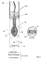
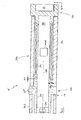
- Fig. 4 shows the handle 26 of the Fig. 1 in detail, wherein in particular an inner life of the handle 26 is shown.
- the controller 60 may be integrated with the handle 26.
- the controller 60 has a signal generator 62, a signal sensor 64, which may both be arranged in a housing 66, and an evaluation unit 68.
- a signal generator 62 an exciter magnet is considered below by way of example.
- a signal sensor 64 a group of magnetic field sensors, such as e.g. Hall sensors, considered. It is understood that in addition to the magnetic action principle shown here by way of example, it is also possible to work inductively, capacitively or optically.
- a microprocessor may be used as the evaluation unit 68, which has stored in its program memory corresponding evaluation and control programs to generate the desired control signals for the drives 40 from the values measured with the signal sensor 64.
- the signal generator 62 or the signal sensor 64 is firmly connected to the handle 26, wherein the handle 26 relative to the frame 12 movable (rotatable and possibly displaceable) is mounted.
- the counter component (sensor 64 / encoder 62) is then fixedly connected to the frame 12 and in particular to the end 24 of the tube 20-2.
- the signal sensor 64 senses magnetic field changes in a location-sensitive manner and converts these into corresponding output signals which are sent to the evaluation unit 68. In the evaluation unit 68, these signals are evaluated and converted into corresponding control signals, which are then transmitted to the drives 40-1 and 40-2.
- the actuators 40-1 and 40-2 are operated synchronously when the carriage 10 is to travel forwards or backwards. The actuators 40-1 and 40-2 are operated differently when the carriage 10 is to go to the left or right. additionally
- the evaluation unit 68 can generate further control signals based on signals supplied by the position sensor (s) 44 which, for example, brake the carriage 10 when the carriage 10 is to be moved downhill.
- the drives 40 can be more strongly controlled to compensate for the slope, so that the car 10 is usually self-propelled at a constant or at a speed adapted to the environment. The user does not need to expend any force to move the carriage 10, except to change the position of the handle 26 according to his driving desire.
- the evaluation unit is connected via lines 70 to the signal sensor 64.
- an (individually) coded transmitter-receiver unit, or a component thereof, can also be seated in the grip sleeve 72, so that the evaluation unit 68 can only be activated if a corresponding counterpart is arranged in the immediate vicinity of the handle 26 is.
- This unit may e.g. be realized in the form of an RFID receiver 74 and an RFID chip 76.
- the RFID receiver 74 may be, e.g. front side, be integrated into the grip sleeve 72, whereas the RFID chip 76 is carried by the user of the carriage 10, such as. in the form of a bracelet.
- Fig. 5 shows one of the drives 40 in an isolated perspective view.
- the (coaxial) rotation and mounting axis of Fig. 1 is indicated by a dot-dash line.
- the position sensor 44 is arranged on a printed circuit board not designated here in detail, which in turn is connected directly to the drive 40 (for example, inside the front side).
- the drive 40 is to be installed in the frame 12 in such an orientation that the position sensor 44 is preferably in a horizontal plane when the carriage 10 is in a horizontal plane.
- the position sensor 44 provides detection of the terrain. So (automatic) accelerations are possible when driving uphill as well as braking maneuvers when driving downhill. Similarly, tilting on slopes can cause tipping over in time be prevented by the controller prevents a drive into a critical area.
- Fig. 6 shows an exploded view of one of the wheels 14 of the Fig. 1 , wherein the front wheel 16 differs from the rear wheel 18 only in the dimensioning.
- the rear wheels (diameter eg 300 mm) are usually larger, and possibly also wider, than the or the front wheels 16 (diameter eg 180 mm).
- the structure of the front wheel 16 is otherwise preferably equal to the structure of the rear wheel 18th
- the exemplary wheel 14 of the Fig. 6 has a tire 100 with an unspecified profile in the circumferential direction and a rim 102.
- the rim 102 includes a rim base 104, one or more spokes 106, a hub 108 and a corresponding plurality of spoke pins 110 for securing the spokes 106 between the rim base 104 and the hub 108.
- the rim base 104 has a body 112 which is formed as a hollow cylinder.
- the body 112 has an inner circumferential surface 114 and an outer circumferential surface 116.
- the rim base 104 is disposed with the hub 108 coaxially along a (rotary) axis 118.
- the spokes 106 are oriented in the radial direction. In the example of Fig. 6 For example, three spokes 106-1 to 106-3 are shown, which are each arranged at an angle of 120 ° relative to each other.
- the spokes 106 may include a plate-shaped body 120 having a preferably centered through-hole 122 in the radial direction to guide the spoke pin 110 through the body 120.
- the spoke pin 110 is formed correspondingly long.
- the hub 108 which is preferably also cylindrical in shape, has corresponding openings 124 for receiving the spoke pins 110 in its outer jacket.
- the openings 124 may be provided with an internal thread.
- the openings 124 may be blind holes.
- the hub 108 may incorporate a quick release (not shown) to secure the wheel to its axis of rotation, such as on one of the output shafts 42 (see FIG. Fig. 2 ).
- the spoke pin 110 may have at its radially outer end a bolt head 125, which in a correspondingly sized recess 126 can be received in the outer circumferential surface 116 of the rim base 104.
- the recess 126 may be formed so that the bolt head 125 is positively received (not shown).
- a bolt head 125 opposite end of the spoke pin 110 may be formed conically to sit in the correspondingly shaped opening 124 of the hub 108, for example in a press fit.
- spoke pin 110 is preferably as long in the axial direction as the rim base 104 and the hub 108, optional additional locating and centering pins 130 may be provided that extend between the spoke 106 and the hub 108 as well as between the hub Spoke 106 and the rim base 104 are arranged.
- the pins 130 are preferably disposed around the spoke pin 110 (left and right thereof).
- a big advantage of the wheel 14 is its construction. To manufacture the wheel no expensive injection molding tools are required.
- the in the Fig. 6 components shown can be produced, for example, by machining.
- the spokes 106 are interchangeable. The user can order spokes 106 and remove and install them yourself.
- the spoke 106 may be made of various materials, such as carbon, wood, glass, metal, etc., especially in arbitrary colors.
- the wheel 14 of the Fig. 6 and in particular the spokes 106 are characterized by a high strength and durability, especially when aluminum is used for the production.
- Fig. 7 shows a partial perspective view of another embodiment of a handle 26 'in an exploded view, which like the handle 26 of Fig. 2 relative to the tube 20-2 and the end 24 is oriented.
- the handle 26 ' extends substantially along the transverse direction Y, is oriented horizontally (preferably horizontally) and has a carrier element 300, a gripping sleeve 302 and at least one connecting element 304. Further, a lid member 306 is provided.
- the end 24 of the tube 20-2, the connecting element 304, the carrier element 300, the gripping sleeve 302 and the cover element 306 are arranged coaxially to a longitudinal axis 308 of the handle 26 ', which extends parallel to the transverse direction Y.
- the connecting element 304 is non-rotatable with the End 24 connected and may have an LED 307 to indicate the state of charge of the battery.
- the carrier element (eg a flat steel) 300 is rotatably and axially immovably connected to the connecting element 304.
- the grip sleeve 302 is movable, preferably floating, mounted on the carrier element 300.
- the lid member 308 is rotatably and axially immovably connected to the support member 300.
- the gripping sleeve 302 is mounted on the carrier element 300 in such a way that the gripping sleeve 302 - in relation to which it is rigid with the frame 12 (FIG. Fig.
- the signal transmitter 62 (not shown) and signal sensor or receiver 64 are spaced apart from each other, connected to the carrier element 300 (fixed to the frame) and the grip sleeve 302 (movable) and communicate with each other via a field. If the relative position of the movable sensor component (signal generator 62 or signal sensor 64) changes, there is a change in the local field strength, which can be measured and evaluated.
- Fig. 8 shows a sectional view of the handle 26 'along a plane VIII-VIII in Fig. 7 , In the Fig. 8 you look in the Z direction on the XY plane of the Fig. 7 ,
- the connecting element 304 has a hollow-cylindrical body 312, which is designed to receive the carrier element 300.
- the support member 300 extends through the body 312.
- a preferably multi-pole plug 310 can be provided on the carrier element 300, which can be coupled non-rotatably and immovably to a counterpart (not shown here) which is rigidly connected to the frame 12 (non-rotatably). It is understood that the counterpart can also be integrated into the body 312, so that it no longer has to be hollow-cylindrical.
- the lid member 306 rotatably and immovably be attached to the support member 300, for example.
- the lid member 306 is then also rigidly connected to the frame 12 of the carriage 10.
- the lid member 306 may include the RFID receiver 74 (see Fig. 4 ). In this case, the evaluation unit 68 and the RFID receiver 74 are electrically connected.
- the grip sleeve 302 has a sleeve-shaped body 314 which is movably mounted on the carrier element 300.
- the bodies 312 and 314 are shaped accordingly. Between the bodies 312 and 314, bearings (e.g., a sealing silicone mass or the like) not shown in detail may be provided to permit relative movement between the bodies 312 and 314.
- the body 314 sits radially on the outside, preferably without direct contact, on the body 312.
- a gripping sleeve 316 can rest radially on the outside, which is preferably elastic in order to create a good haptic feel for the user.
- the handle cover 316 may be made of sponge rubber or leather, for example, and have a thickness of a few millimeters. The handle cover can easily protrude above the body 314 at both axial ends. When assembled, the handle cover 316 may abut the connecting element 304 and the cover element 306 in the axial direction, in particular in order to axially fix the grip sleeve 302, wherein the fixing furthermore permits the relative movements required for the control of the carriage 10.
- the handle cover 316 is replaceable and preferably fits in a press fit on the body 314.
- the axial modular design of the overall assembly allows for easy assembly and disassembly.
- Fig. 9 shows a sectional view taken along the plane VIIII - VIIII of Fig. 7 by the carrier element 300 and the gripping sleeve 302.
- the carrier element 300 is here exemplarily implemented in the form of a cuboid piece of steel, on which a printed circuit board 318 is fixed, which carries an integrated chip (IC) 320.
- the IC 320 implements both the evaluation unit 68 and the signal sensor 64.
- the signal sensor is implemented by Hall sensors 322, which interact with a (permanent) magnet 324 as a signal generator 62.
- the magnet 324 is held by a magnetic holder 326 on an inner wall of the body 314 and is thus fixedly connected to the grip sleeve 302.
- the IC 320 may also include a microprocessor
- the game S1 illustrates the relative mobility in the axial direction and may be on the order of 1.5 to 2 mm.
- the game S2 illustrates the radial mobility and may also be in the order of 1.5 to 2 mm.
- a speed control can be effected via a force of the user on the grip sleeve 302. Pressing forwards more (V) increases the speed. Pulling it backwards (H) can reduce the speed, while at the same time supporting steering movements. In the simplest case, only forward and rearward travel is assisted, with cornering being achieved by lifting one of the rear wheels, which in turn can be effected by pressing the handle 26 'down (negative Z direction).
- the evaluation unit 68 is able to effect the desired accelerations / direction changes on the basis of the forces exerted on the handle 26 '. For this, the field changes are evaluated accordingly. Controlled braking is possible. An automatic braking e.g. on the mountain or in an inclined position is possible. For this purpose, corresponding procedures can be stored in the microprocessor, which intervene with corresponding parameters at the sensors 44 and / or 64.
- a driving movement of the carriage 10 takes place with a damped reaction time to the operation of the handle. With very strong pressure on the handle, the acceleration is preferably carried out not jerky.
- a straight-ahead driving or freewheeling mode is ensured by the evaluation unit 68.
- the motors In park mode and in stand-by mode, the motors are actively braked, ie, the motors must be able to be controlled in both directions at standstill to prevent the carriage 10 from rolling forward or backward.
- a temperature monitoring of the motors can be provided to compensate for fluctuations in efficiency. The heat development of the motors has to be considered.
Landscapes
- Health & Medical Sciences (AREA)
- General Health & Medical Sciences (AREA)
- Physical Education & Sports Medicine (AREA)
- Handcart (AREA)
Applications Claiming Priority (1)
| Application Number | Priority Date | Filing Date | Title |
|---|---|---|---|
| DE102012007487A DE102012007487A1 (de) | 2012-03-30 | 2012-03-30 | Golfwagen mit intuitiver Steuerung und neuartigen Rädern |
Publications (2)
| Publication Number | Publication Date |
|---|---|
| EP2644232A1 true EP2644232A1 (fr) | 2013-10-02 |
| EP2644232B1 EP2644232B1 (fr) | 2015-03-18 |
Family
ID=48013861
Family Applications (1)
| Application Number | Title | Priority Date | Filing Date |
|---|---|---|---|
| EP13162023.9A Not-in-force EP2644232B1 (fr) | 2012-03-30 | 2013-04-02 | Chariot de golf à commande intuitive et roues d'un nouveau type |
Country Status (2)
| Country | Link |
|---|---|
| EP (1) | EP2644232B1 (fr) |
| DE (1) | DE102012007487A1 (fr) |
Cited By (3)
| Publication number | Priority date | Publication date | Assignee | Title |
|---|---|---|---|---|
| EP3615398A1 (fr) * | 2017-04-27 | 2020-03-04 | Robert Bosch GmbH | Dispositif roue entraîné par un moteur électrique |
| EP3747732A1 (fr) | 2019-06-05 | 2020-12-09 | Peter Ganser | Chariot de golf |
| WO2021078907A1 (fr) * | 2019-10-22 | 2021-04-29 | Powakaddy International Limited | Chariot de golf motorisé |
Families Citing this family (1)
| Publication number | Priority date | Publication date | Assignee | Title |
|---|---|---|---|---|
| US8991529B2 (en) * | 2013-01-21 | 2015-03-31 | GM Global Technology Operations LLC | Self-motivated cargo pod |
Citations (8)
| Publication number | Priority date | Publication date | Assignee | Title |
|---|---|---|---|---|
| US3720281A (en) * | 1971-02-16 | 1973-03-13 | J Frownfelter | Remotely controlled vehicle |
| US3976151A (en) | 1971-07-26 | 1976-08-24 | Citation Manufacturing Company, Inc. | Self-propelled golf cart |
| US5350982A (en) * | 1992-12-16 | 1994-09-27 | Seib James N | Motorized golf bag cart circuit and apparatus |
| US5789884A (en) * | 1996-03-25 | 1998-08-04 | Hancock; Frank John Thompson | Control arrangement for motorised trolley |
| DE20307742U1 (de) | 2003-01-22 | 2003-07-31 | Wahler, Peter, 50674 Köln | Trolley zum Transport einer Golftasche |
| WO2007013084A1 (fr) * | 2005-07-28 | 2007-02-01 | Shai Gal | Vehicule automoteur avec choix de modes de fonctionnement |
| DE202007005290U1 (de) | 2007-04-12 | 2007-06-21 | Kiffe Engineering Gmbh | Golf-Caddie |
| WO2008089576A1 (fr) * | 2007-01-26 | 2008-07-31 | Jackson George W | Chariot de sac de golf motorisé |
-
2012
- 2012-03-30 DE DE102012007487A patent/DE102012007487A1/de not_active Ceased
-
2013
- 2013-04-02 EP EP13162023.9A patent/EP2644232B1/fr not_active Not-in-force
Patent Citations (8)
| Publication number | Priority date | Publication date | Assignee | Title |
|---|---|---|---|---|
| US3720281A (en) * | 1971-02-16 | 1973-03-13 | J Frownfelter | Remotely controlled vehicle |
| US3976151A (en) | 1971-07-26 | 1976-08-24 | Citation Manufacturing Company, Inc. | Self-propelled golf cart |
| US5350982A (en) * | 1992-12-16 | 1994-09-27 | Seib James N | Motorized golf bag cart circuit and apparatus |
| US5789884A (en) * | 1996-03-25 | 1998-08-04 | Hancock; Frank John Thompson | Control arrangement for motorised trolley |
| DE20307742U1 (de) | 2003-01-22 | 2003-07-31 | Wahler, Peter, 50674 Köln | Trolley zum Transport einer Golftasche |
| WO2007013084A1 (fr) * | 2005-07-28 | 2007-02-01 | Shai Gal | Vehicule automoteur avec choix de modes de fonctionnement |
| WO2008089576A1 (fr) * | 2007-01-26 | 2008-07-31 | Jackson George W | Chariot de sac de golf motorisé |
| DE202007005290U1 (de) | 2007-04-12 | 2007-06-21 | Kiffe Engineering Gmbh | Golf-Caddie |
Cited By (5)
| Publication number | Priority date | Publication date | Assignee | Title |
|---|---|---|---|---|
| EP3615398A1 (fr) * | 2017-04-27 | 2020-03-04 | Robert Bosch GmbH | Dispositif roue entraîné par un moteur électrique |
| EP3747732A1 (fr) | 2019-06-05 | 2020-12-09 | Peter Ganser | Chariot de golf |
| WO2021078907A1 (fr) * | 2019-10-22 | 2021-04-29 | Powakaddy International Limited | Chariot de golf motorisé |
| GB2603865A (en) * | 2019-10-22 | 2022-08-17 | Powakaddy International Ltd | Powered golf trolley |
| GB2603865B (en) * | 2019-10-22 | 2023-11-15 | Powakaddy International Ltd | Powered golf trolley |
Also Published As
| Publication number | Publication date |
|---|---|
| EP2644232B1 (fr) | 2015-03-18 |
| DE102012007487A1 (de) | 2013-10-02 |
Similar Documents
| Publication | Publication Date | Title |
|---|---|---|
| US10703401B2 (en) | Powered utility cart and compliant drive wheel therefor | |
| EP2455277B1 (fr) | Entraînement auxiliaire | |
| EP2755886B1 (fr) | Véhicule de transport doté d'un châssis à trois roues | |
| EP2895373B1 (fr) | Chariot et kit de conversion d'un tel chariot | |
| DE102011084754B4 (de) | Elektromotorisch unterstützter, intuitiv durch Muskelkraft antreibbarer Tretroller und Verfahren zum Betreiben eines elektromotorisch unterstützten, durch Muskelkraft antreibbaren Tretrollers | |
| EP2627554B1 (fr) | Véhicule contrôlable par déplacement du poids avec planche de conduite divisée en deux | |
| EP3514047B1 (fr) | Commande de freinage sans fil | |
| EP2644232B1 (fr) | Chariot de golf à commande intuitive et roues d'un nouveau type | |
| EP3501468B1 (fr) | Dispositif de précontrainte de direction pour un fauteuil roulant et fauteuil roulant comportant un dispositif de précontrainte de direction | |
| DE202019003072U1 (de) | Fahrplattform und modulare Fahreinheit | |
| WO2024227212A2 (fr) | Système d'entraînement pour un véhicule de transport sans conducteur | |
| DE102013001766B4 (de) | Transportwagen mit selbstaufladendem Rangierantrieb für den freien Transport von Bauteilen in Fabriken | |
| EP3170722B1 (fr) | Procédé et dispositif de montage d'un véhicule, en particulier un véhicule utilitaire | |
| DE102021201502A1 (de) | Steuervorrichtung eines menschlich angetriebenen fahrzeugs | |
| DE102018210452A1 (de) | Elektrifizierte Achse | |
| DE102015119384A1 (de) | Elektrisches Antriebssystem für einen Transportwagen, insbesondere Kinderwagen und Transportwagen, insbesondere Kinderwagen mit einem elektrischen Antriebssystem | |
| DE102019126096A1 (de) | Fahrzeug | |
| DE102011087072A1 (de) | Elektrisch betriebener Transportwagen | |
| DE102022110612A1 (de) | Freizeitfahrzeug, Freizeitanhänger, Anordnung zur Vorgabe von Abstellplätzen für Freizeitanhänger sowie System und Verfahren für einen Freizeitanhänger | |
| DE202015106061U1 (de) | Elektrisches Antriebssystem für einen Transportwagen, insbesondere Kinderwagen und Transportwagen, insbesondere Kinderwagen mit einem elektrischen Antriebssystem | |
| DE102020000032A1 (de) | Kopplungsvorrichtung und mobile Geh-Hilfe zum Ankoppeln eines selbstbalancierenden Fahrzeugs | |
| DE102019126097A1 (de) | Fahrzeug | |
| DE102011087069B4 (de) | Elektrisch betriebener Transportwagen und Verfahren zur Bewegungssteuerung eines elektrisch betriebenen Transportwagens | |
| DE102012215417A1 (de) | Dreirädriger und elektrisch betriebener Golftrolley | |
| DE202005013177U1 (de) | Elektromotorisch betriebener Golfkarren |
Legal Events
| Date | Code | Title | Description |
|---|---|---|---|
| PUAI | Public reference made under article 153(3) epc to a published international application that has entered the european phase |
Free format text: ORIGINAL CODE: 0009012 |
|
| AK | Designated contracting states |
Kind code of ref document: A1 Designated state(s): AL AT BE BG CH CY CZ DE DK EE ES FI FR GB GR HR HU IE IS IT LI LT LU LV MC MK MT NL NO PL PT RO RS SE SI SK SM TR |
|
| AX | Request for extension of the european patent |
Extension state: BA ME |
|
| 17P | Request for examination filed |
Effective date: 20131024 |
|
| RBV | Designated contracting states (corrected) |
Designated state(s): AL AT BE BG CH CY CZ DE DK EE ES FI FR GB GR HR HU IE IS IT LI LT LU LV MC MK MT NL NO PL PT RO RS SE SI SK SM TR |
|
| RIC1 | Information provided on ipc code assigned before grant |
Ipc: A63B 55/08 20060101AFI20140804BHEP |
|
| GRAP | Despatch of communication of intention to grant a patent |
Free format text: ORIGINAL CODE: EPIDOSNIGR1 |
|
| INTG | Intention to grant announced |
Effective date: 20140912 |
|
| GRAS | Grant fee paid |
Free format text: ORIGINAL CODE: EPIDOSNIGR3 |
|
| REG | Reference to a national code |
Ref country code: DE Ref legal event code: R079 Ref document number: 502013000470 Country of ref document: DE Free format text: PREVIOUS MAIN CLASS: A63B0055080000 Ipc: A63B0055600000 |
|
| GRAA | (expected) grant |
Free format text: ORIGINAL CODE: 0009210 |
|
| AK | Designated contracting states |
Kind code of ref document: B1 Designated state(s): AL AT BE BG CH CY CZ DE DK EE ES FI FR GB GR HR HU IE IS IT LI LT LU LV MC MK MT NL NO PL PT RO RS SE SI SK SM TR |
|
| REG | Reference to a national code |
Ref country code: GB Ref legal event code: FG4D Free format text: NOT ENGLISH |
|
| RIC1 | Information provided on ipc code assigned before grant |
Ipc: A63B 55/60 20150101AFI20150211BHEP |
|
| REG | Reference to a national code |
Ref country code: CH Ref legal event code: EP |
|
| REG | Reference to a national code |
Ref country code: IE Ref legal event code: FG4D Free format text: LANGUAGE OF EP DOCUMENT: GERMAN |
|
| REG | Reference to a national code |
Ref country code: AT Ref legal event code: REF Ref document number: 716160 Country of ref document: AT Kind code of ref document: T Effective date: 20150415 |
|
| REG | Reference to a national code |
Ref country code: DE Ref legal event code: R096 Ref document number: 502013000470 Country of ref document: DE Effective date: 20150430 |
|
| REG | Reference to a national code |
Ref country code: NL Ref legal event code: VDEP Effective date: 20150318 |
|
| REG | Reference to a national code |
Ref country code: NL Ref legal event code: VDEP Effective date: 20150318 |
|
| PG25 | Lapsed in a contracting state [announced via postgrant information from national office to epo] |
Ref country code: SE Free format text: LAPSE BECAUSE OF FAILURE TO SUBMIT A TRANSLATION OF THE DESCRIPTION OR TO PAY THE FEE WITHIN THE PRESCRIBED TIME-LIMIT Effective date: 20150318 Ref country code: HR Free format text: LAPSE BECAUSE OF FAILURE TO SUBMIT A TRANSLATION OF THE DESCRIPTION OR TO PAY THE FEE WITHIN THE PRESCRIBED TIME-LIMIT Effective date: 20150318 Ref country code: NO Free format text: LAPSE BECAUSE OF FAILURE TO SUBMIT A TRANSLATION OF THE DESCRIPTION OR TO PAY THE FEE WITHIN THE PRESCRIBED TIME-LIMIT Effective date: 20150618 Ref country code: LT Free format text: LAPSE BECAUSE OF FAILURE TO SUBMIT A TRANSLATION OF THE DESCRIPTION OR TO PAY THE FEE WITHIN THE PRESCRIBED TIME-LIMIT Effective date: 20150318 Ref country code: FI Free format text: LAPSE BECAUSE OF FAILURE TO SUBMIT A TRANSLATION OF THE DESCRIPTION OR TO PAY THE FEE WITHIN THE PRESCRIBED TIME-LIMIT Effective date: 20150318 |
|
| REG | Reference to a national code |
Ref country code: LT Ref legal event code: MG4D |
|
| PG25 | Lapsed in a contracting state [announced via postgrant information from national office to epo] |
Ref country code: GR Free format text: LAPSE BECAUSE OF FAILURE TO SUBMIT A TRANSLATION OF THE DESCRIPTION OR TO PAY THE FEE WITHIN THE PRESCRIBED TIME-LIMIT Effective date: 20150619 Ref country code: LV Free format text: LAPSE BECAUSE OF FAILURE TO SUBMIT A TRANSLATION OF THE DESCRIPTION OR TO PAY THE FEE WITHIN THE PRESCRIBED TIME-LIMIT Effective date: 20150318 Ref country code: RS Free format text: LAPSE BECAUSE OF FAILURE TO SUBMIT A TRANSLATION OF THE DESCRIPTION OR TO PAY THE FEE WITHIN THE PRESCRIBED TIME-LIMIT Effective date: 20150318 |
|
| PG25 | Lapsed in a contracting state [announced via postgrant information from national office to epo] |
Ref country code: NL Free format text: LAPSE BECAUSE OF FAILURE TO SUBMIT A TRANSLATION OF THE DESCRIPTION OR TO PAY THE FEE WITHIN THE PRESCRIBED TIME-LIMIT Effective date: 20150318 |
|
| PG25 | Lapsed in a contracting state [announced via postgrant information from national office to epo] |
Ref country code: EE Free format text: LAPSE BECAUSE OF FAILURE TO SUBMIT A TRANSLATION OF THE DESCRIPTION OR TO PAY THE FEE WITHIN THE PRESCRIBED TIME-LIMIT Effective date: 20150318 Ref country code: SK Free format text: LAPSE BECAUSE OF FAILURE TO SUBMIT A TRANSLATION OF THE DESCRIPTION OR TO PAY THE FEE WITHIN THE PRESCRIBED TIME-LIMIT Effective date: 20150318 Ref country code: PT Free format text: LAPSE BECAUSE OF FAILURE TO SUBMIT A TRANSLATION OF THE DESCRIPTION OR TO PAY THE FEE WITHIN THE PRESCRIBED TIME-LIMIT Effective date: 20150720 Ref country code: RO Free format text: LAPSE BECAUSE OF FAILURE TO SUBMIT A TRANSLATION OF THE DESCRIPTION OR TO PAY THE FEE WITHIN THE PRESCRIBED TIME-LIMIT Effective date: 20150318 Ref country code: CZ Free format text: LAPSE BECAUSE OF FAILURE TO SUBMIT A TRANSLATION OF THE DESCRIPTION OR TO PAY THE FEE WITHIN THE PRESCRIBED TIME-LIMIT Effective date: 20150318 Ref country code: ES Free format text: LAPSE BECAUSE OF FAILURE TO SUBMIT A TRANSLATION OF THE DESCRIPTION OR TO PAY THE FEE WITHIN THE PRESCRIBED TIME-LIMIT Effective date: 20150318 |
|
| PG25 | Lapsed in a contracting state [announced via postgrant information from national office to epo] |
Ref country code: MC Free format text: LAPSE BECAUSE OF FAILURE TO SUBMIT A TRANSLATION OF THE DESCRIPTION OR TO PAY THE FEE WITHIN THE PRESCRIBED TIME-LIMIT Effective date: 20150318 Ref country code: PL Free format text: LAPSE BECAUSE OF FAILURE TO SUBMIT A TRANSLATION OF THE DESCRIPTION OR TO PAY THE FEE WITHIN THE PRESCRIBED TIME-LIMIT Effective date: 20150318 Ref country code: IS Free format text: LAPSE BECAUSE OF FAILURE TO SUBMIT A TRANSLATION OF THE DESCRIPTION OR TO PAY THE FEE WITHIN THE PRESCRIBED TIME-LIMIT Effective date: 20150718 |
|
| REG | Reference to a national code |
Ref country code: DE Ref legal event code: R097 Ref document number: 502013000470 Country of ref document: DE |
|
| PG25 | Lapsed in a contracting state [announced via postgrant information from national office to epo] |
Ref country code: IT Free format text: LAPSE BECAUSE OF FAILURE TO SUBMIT A TRANSLATION OF THE DESCRIPTION OR TO PAY THE FEE WITHIN THE PRESCRIBED TIME-LIMIT Effective date: 20150318 |
|
| PLBE | No opposition filed within time limit |
Free format text: ORIGINAL CODE: 0009261 |
|
| STAA | Information on the status of an ep patent application or granted ep patent |
Free format text: STATUS: NO OPPOSITION FILED WITHIN TIME LIMIT |
|
| REG | Reference to a national code |
Ref country code: IE Ref legal event code: MM4A |
|
| PG25 | Lapsed in a contracting state [announced via postgrant information from national office to epo] |
Ref country code: DK Free format text: LAPSE BECAUSE OF FAILURE TO SUBMIT A TRANSLATION OF THE DESCRIPTION OR TO PAY THE FEE WITHIN THE PRESCRIBED TIME-LIMIT Effective date: 20150318 |
|
| REG | Reference to a national code |
Ref country code: FR Ref legal event code: ST Effective date: 20151231 |
|
| 26N | No opposition filed |
Effective date: 20151221 |
|
| PG25 | Lapsed in a contracting state [announced via postgrant information from national office to epo] |
Ref country code: FR Free format text: LAPSE BECAUSE OF NON-PAYMENT OF DUE FEES Effective date: 20150518 Ref country code: SI Free format text: LAPSE BECAUSE OF FAILURE TO SUBMIT A TRANSLATION OF THE DESCRIPTION OR TO PAY THE FEE WITHIN THE PRESCRIBED TIME-LIMIT Effective date: 20150318 |
|
| PG25 | Lapsed in a contracting state [announced via postgrant information from national office to epo] |
Ref country code: IE Free format text: LAPSE BECAUSE OF NON-PAYMENT OF DUE FEES Effective date: 20150402 |
|
| REG | Reference to a national code |
Ref country code: CH Ref legal event code: PL |
|
| PG25 | Lapsed in a contracting state [announced via postgrant information from national office to epo] |
Ref country code: MT Free format text: LAPSE BECAUSE OF FAILURE TO SUBMIT A TRANSLATION OF THE DESCRIPTION OR TO PAY THE FEE WITHIN THE PRESCRIBED TIME-LIMIT Effective date: 20150318 |
|
| PG25 | Lapsed in a contracting state [announced via postgrant information from national office to epo] |
Ref country code: CH Free format text: LAPSE BECAUSE OF NON-PAYMENT OF DUE FEES Effective date: 20160430 Ref country code: LI Free format text: LAPSE BECAUSE OF NON-PAYMENT OF DUE FEES Effective date: 20160430 |
|
| PG25 | Lapsed in a contracting state [announced via postgrant information from national office to epo] |
Ref country code: HU Free format text: LAPSE BECAUSE OF FAILURE TO SUBMIT A TRANSLATION OF THE DESCRIPTION OR TO PAY THE FEE WITHIN THE PRESCRIBED TIME-LIMIT; INVALID AB INITIO Effective date: 20130402 Ref country code: BG Free format text: LAPSE BECAUSE OF FAILURE TO SUBMIT A TRANSLATION OF THE DESCRIPTION OR TO PAY THE FEE WITHIN THE PRESCRIBED TIME-LIMIT Effective date: 20150318 |
|
| PG25 | Lapsed in a contracting state [announced via postgrant information from national office to epo] |
Ref country code: CY Free format text: LAPSE BECAUSE OF FAILURE TO SUBMIT A TRANSLATION OF THE DESCRIPTION OR TO PAY THE FEE WITHIN THE PRESCRIBED TIME-LIMIT Effective date: 20150318 |
|
| PG25 | Lapsed in a contracting state [announced via postgrant information from national office to epo] |
Ref country code: BE Free format text: LAPSE BECAUSE OF NON-PAYMENT OF DUE FEES Effective date: 20150430 |
|
| PG25 | Lapsed in a contracting state [announced via postgrant information from national office to epo] |
Ref country code: TR Free format text: LAPSE BECAUSE OF FAILURE TO SUBMIT A TRANSLATION OF THE DESCRIPTION OR TO PAY THE FEE WITHIN THE PRESCRIBED TIME-LIMIT Effective date: 20150318 |
|
| PG25 | Lapsed in a contracting state [announced via postgrant information from national office to epo] |
Ref country code: LU Free format text: LAPSE BECAUSE OF NON-PAYMENT OF DUE FEES Effective date: 20150402 |
|
| GBPC | Gb: european patent ceased through non-payment of renewal fee |
Effective date: 20170402 |
|
| PG25 | Lapsed in a contracting state [announced via postgrant information from national office to epo] |
Ref country code: GB Free format text: LAPSE BECAUSE OF NON-PAYMENT OF DUE FEES Effective date: 20170402 |
|
| PG25 | Lapsed in a contracting state [announced via postgrant information from national office to epo] |
Ref country code: SM Free format text: LAPSE BECAUSE OF FAILURE TO SUBMIT A TRANSLATION OF THE DESCRIPTION OR TO PAY THE FEE WITHIN THE PRESCRIBED TIME-LIMIT Effective date: 20150318 |
|
| PG25 | Lapsed in a contracting state [announced via postgrant information from national office to epo] |
Ref country code: MK Free format text: LAPSE BECAUSE OF FAILURE TO SUBMIT A TRANSLATION OF THE DESCRIPTION OR TO PAY THE FEE WITHIN THE PRESCRIBED TIME-LIMIT Effective date: 20150318 |
|
| PGFP | Annual fee paid to national office [announced via postgrant information from national office to epo] |
Ref country code: DE Payment date: 20180124 Year of fee payment: 6 |
|
| PG25 | Lapsed in a contracting state [announced via postgrant information from national office to epo] |
Ref country code: AL Free format text: LAPSE BECAUSE OF FAILURE TO SUBMIT A TRANSLATION OF THE DESCRIPTION OR TO PAY THE FEE WITHIN THE PRESCRIBED TIME-LIMIT Effective date: 20150318 |
|
| REG | Reference to a national code |
Ref country code: AT Ref legal event code: MM01 Ref document number: 716160 Country of ref document: AT Kind code of ref document: T Effective date: 20180402 |
|
| PG25 | Lapsed in a contracting state [announced via postgrant information from national office to epo] |
Ref country code: AT Free format text: LAPSE BECAUSE OF NON-PAYMENT OF DUE FEES Effective date: 20180402 |
|
| REG | Reference to a national code |
Ref country code: DE Ref legal event code: R119 Ref document number: 502013000470 Country of ref document: DE |
|
| PG25 | Lapsed in a contracting state [announced via postgrant information from national office to epo] |
Ref country code: DE Free format text: LAPSE BECAUSE OF NON-PAYMENT OF DUE FEES Effective date: 20191101 |